1. Introduction
In 2020, the World Health Organization (WHO) released a report detailing the top ten causes of death, with ischemic heart disease ranking as the leading cause [
1]. Cardiac ischemia, characterized by a partial or complete blockage of blood supply to the heart, poses a significant health risk. If left untreated, it can progress to myocardial infarction, commonly known as heart attack. Fortunately, cardiac ischemia can be detected through an electrocardiogram (ECG), particularly by analyzing the ST segment of the waveform. The detection of ST segment variations, facilitated by continuous and long-term monitoring using integrated systems, has the potential to reduce the mortality rates associated with cardiac ischemia substantially. Despite advancements in ECG-based monitoring for cardiac arrhythmias, the development of integrated circuits specifically targeting cardiac ischemia remains an unmet need.
This article aims to address this gap by exploring the design considerations of an integrated ischemia monitoring system while minimizing its energy consumption.
One crucial challenge is preserving medical information during noise removal in ECG signals. ECG recordings obtained during a patient’s daily activities are inherently noisy due to factors such as respiration, body movements, and muscle contractions, necessitating robust noise reduction techniques. However, the noise frequencies often overlap with those of the ST segment, posing a significant challenge in preserving crucial medical information [
2]. The International Electrotechnical Commission (IEC) has established standards specifying the maximum allowable distortion introduced during ECG processing to ensure the integrity of the ST segment information [
3]. Compliance with these stringent distortion limits is essential to prevent erroneous diagnoses and ensure accurate clinical decision-making.
A previous study focused on the design of an integrated analog front-end (AFE) [
4] capable of amplifying the ECG signal while preserving critical information related to the ST segment. Although such a front-end can effectively attenuate part of the noise, a non-negligible amount of interference remains. In the present work, we shift our attention to the digital domain, developing signal processing algorithms that operate on the digitized output of the AFE to suppress baseline wander while preserving the morphological integrity of the ST segment. Various methods exist for processing ECG signals in embedded systems, ranging from traditional algorithms like the Pan–Tompkins method and its variants [
5,
6] to machine learning approaches [
7,
8]. In this study, we focus on investigating the discrete wavelet transform (DWT), which provides a time-frequency representation of the signal. The DWT can effectively reduce noise [
9,
10], compress ECG data [
11], and extract features for use in neural networks [
12] and heart rate detection algorithms [
13,
14,
15,
16].
The appeal of DWT lies in the fast wavelet transform (FWT) algorithm, which is known for its computational efficiency and is well-suited to integrated processing. The choice of the mother wavelet significantly influences the performance of the transform as it determines the characteristics of the resulting wavelet filters used by the FWT. Thus, carefully selecting the mother wavelet is essential to meet the application’s specific requirements. While comparisons between mother wavelets have been conducted for ECG noise reduction [
9,
10], it is notable that there is a shortage of literature addressing the optimization of DWT specifically for ST segment monitoring, with no existing articles, to the best of our knowledge.
This work aims to address both the challenge of ST segment distortion and the selection of the optimal mother wavelet. We propose a generic architecture for integrated DWT and optimize its parameters for ten different mother wavelets, ensuring compliance with the IEC standard regarding ST segment distortion. We then describe layout designs and post-layout simulations of the integrated DWT configurations to compare their power consumption and chip area, ultimately identifying the most suitable configuration.
The remainder of this article is organized as follows:
Section 2 provides an overview of ECG characteristics and the challenges of on-board ECG-based diagnosis systems.
Section 3 outlines the fast wavelet transform algorithm and introduces the selected mother wavelets.
Section 4 details the customizable architecture and optimization strategies implemented.
Section 5 presents the results and compares them with the existing literature, while
Section 6 concludes this article.
2. Electrocardiogram and Distortions Due to Signal Processing
2.1. Electrocardiogram Characteristics
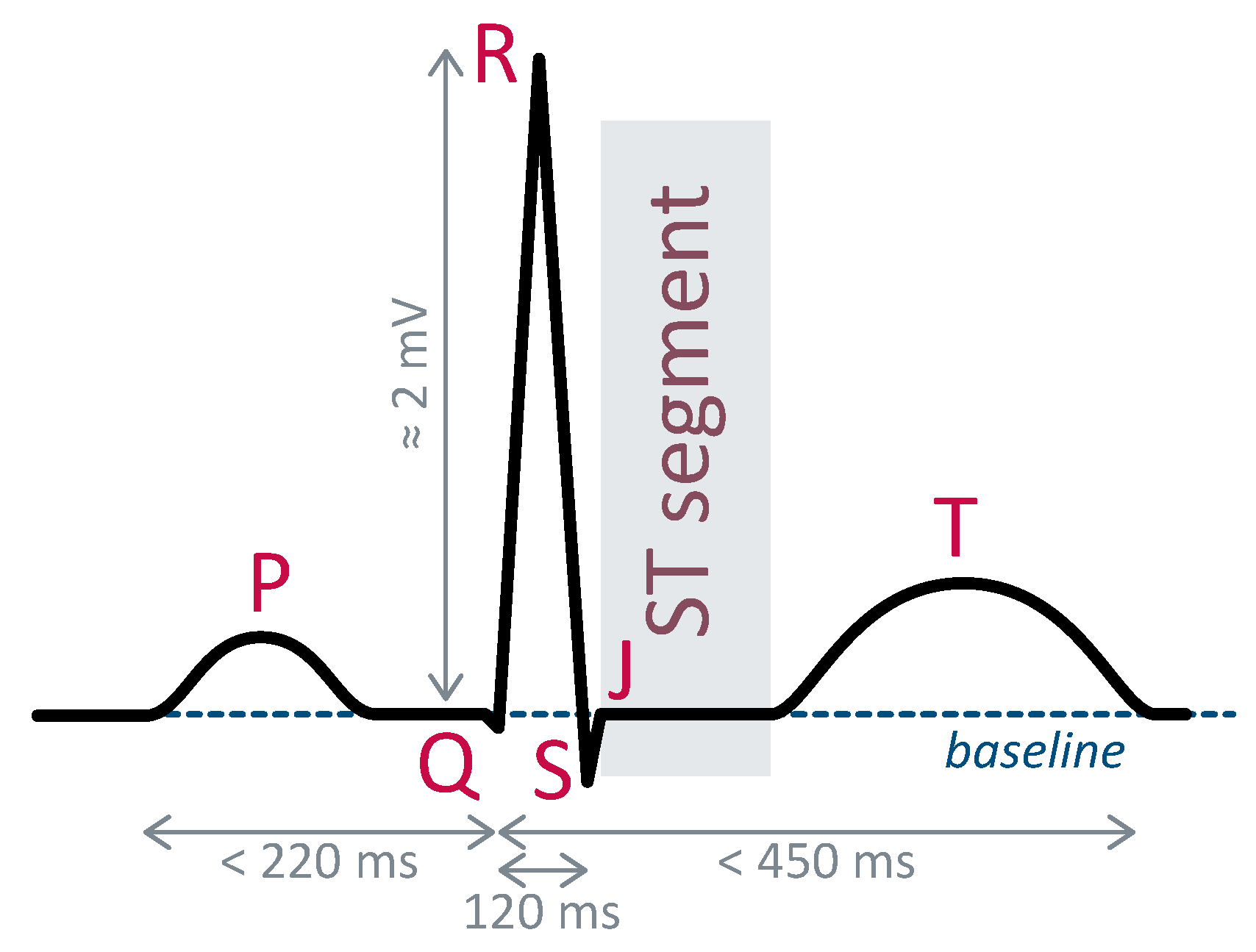
An electrocardiogram (ECG) provides an image of the heart’s electrical activity thanks to electrodes placed on the patient’s chest. It is widely used to diagnose cardiac pathologies. The precise shape of the ECG waveform depends upon the placement of the electrodes, although its fundamental components remain consistent, designated by specific letters.
Figure 1 illustrates the ECG waveform corresponding to electrode placement known as lead II. Due to their distinct and easily identifiable morphology, R-peaks serve as reference points for heartbeat localization. Typically, their detection is an initial step preceding identifying other fiducial points. Electrocardiogram frequencies span from one Hertz to several hundred Hertz [
17].
Diagnoses based on ECG analysis involve assessing disparities between a patient’s healthy reference heartbeat and another one recorded at a specific time. In cases of cardiac ischemia, deviations in the ST segment constitute the primary indicator. This segment should normally align with the baseline. Whether above or below, deviations are signs of signal ischemic events or myocardial infarction [
17].
2.2. Medical Information Distortions and the IEC Standard
The International Electrotechnical Commission (IEC) has established a standard delineating specific electrocardiograph requirements [
3]. The standard specifies a test protocol and associated test signals. To be validated by the standard, all channels of the electrocardiograph should be input by the test signals and the outputs should check requirements.
Figure 2 describes some test signals. CAL 20100 has a shape of heart beat on Lead II. CAL 20110 and CAL 20160 exhibit an up or down ST segment offset. CAL 20000 has a shape close to V2, V3, or V4. Regarding the ST segment, the requirement is that at the output signal, the ST segment should not exceed 25
V from its input level, and its slope should remain below
mV/s.
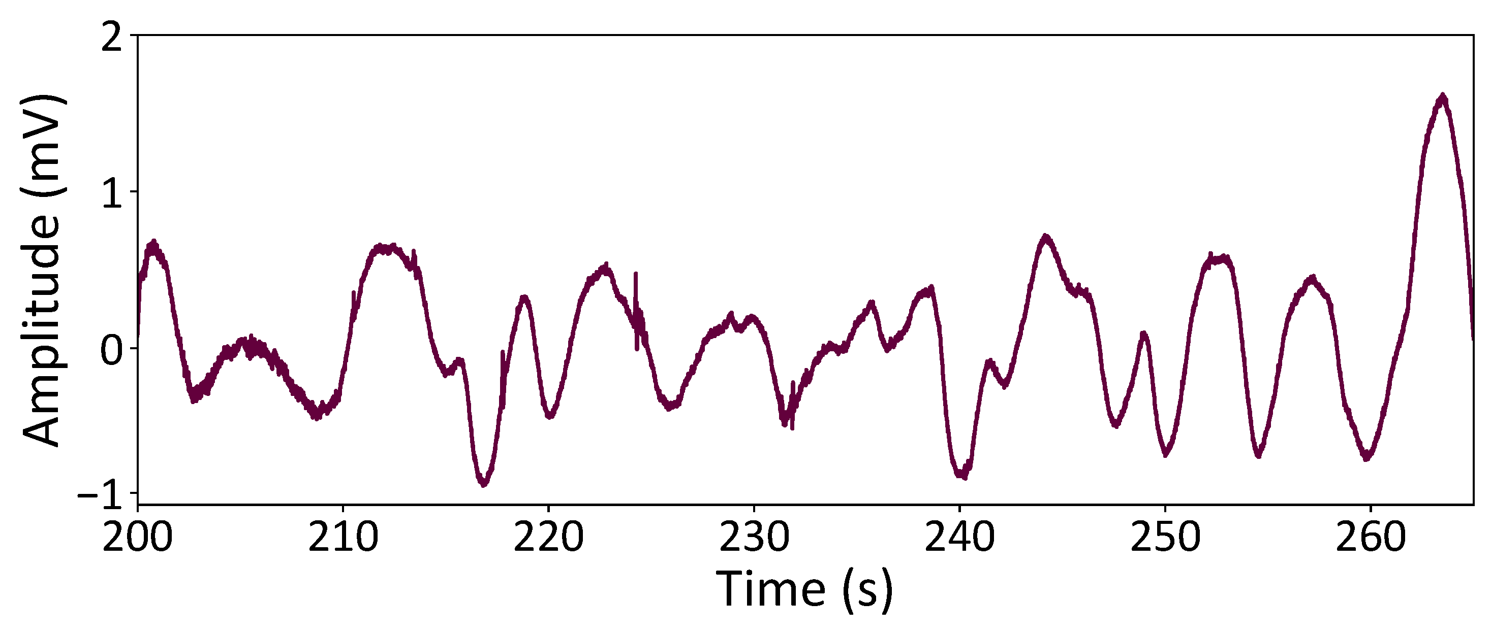
During embedded measurements, the ECG is susceptible to various noise sources, with baseline wandering (BW) emerging as one of the most challenging interferences. BW is intricately linked to respiration and gradual shifts in electrode offset, manifesting as low-frequency noise with considerable amplitudes. Furthermore, BW often intersects with ECG frequencies corresponding to the ST segment.
Figure 3 illustrates the characteristic pattern of BW noise derived from the “bw” record in the MIT-BIH Noise Stress Test database [
18].
For simulation purposes, test signals are generated by concatenating several thousand heartbeats from the CAL20100 database with some variability on the heart rate. To assess ST segment distortion, the test signals are input into the digital system and compared to the ideal reference. Metrics such as maximum ST-level error and maximum ST-slope error are computed. In addition, the Signal-to-Distortion Ratio (SDR) are calculated over the entire signal. To evaluate the system’s baseline wander rejection capability, baseline wander signals from the MIT-BIH database are superimposed on the input. The resulting Signal-to-Noise Ratio Improvement (SNRI) is quantified by computing the difference between the output and input SNR values.
Fulfilling these criteria guided our approach during the digital processing design phase, ensuring the preservation of critical medical information essential for accurately diagnosing cardiac ischemia.
3. The Wavelet Transform
The wavelet transform is extensively employed in the literature for ECG noise removal [
9,
10] and event detection, particularly R-peak detection [
13,
14,
15,
16]. Its suitability for implementation on embedded systems is facilitated by the fast wavelet transform (FWT) algorithm [
19].
Moreover, digital implementations of the FWT documented in the literature demonstrate good performances in power consumption and circuit area efficiency while executing sophisticated signal processing tasks [
15,
16,
20].
3.1. Fast Wavelet Transform
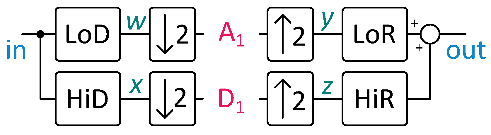
Fast wavelet transform (FWT) uses finite impulse response (FIR) filters and down- and upsampling operations to compute the wavelet transform of a signal. It can reconstruct the original signal from the decomposition using similar operations. This capability enables the storage of filtered ECG beats, facilitating their transmission to cardiologists to confirm or evaluate alerts generated by the embedded system.
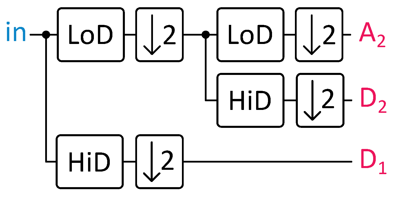
Figure 4 illustrates a single decomposition and reconstruction step. The
coefficients, named approximation coefficients, predominantly cover the signal’s low-frequency components due to the LoD filter’s properties. On the contrary, the
coefficients, known as detail coefficients, tend to cover the high-frequency components.
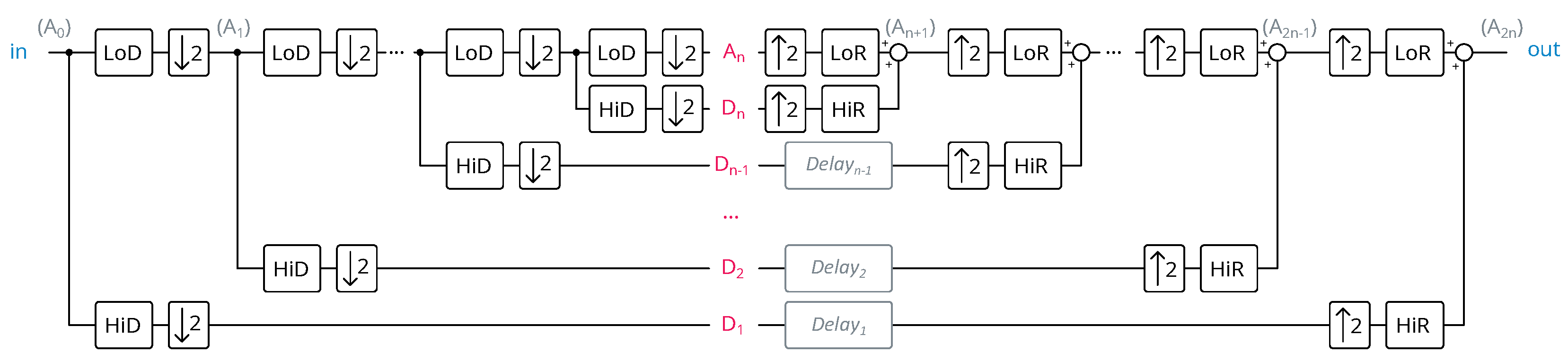
FWT steps can be nested utilizing the approximation coefficients from the previous step as the input signal, thus enabling multi-resolution analysis. The number of nested FWT steps is termed the FWT depth, as depicted in
Figure 5.
The properties of FIR filters partition the signal into components of varying frequencies: contains lower-frequency information, while comprises higher-frequency details. Exploiting these properties enables noise removal or peak detection by processing the appropriate coefficient sets.
Implementing FWT for depths greater than one presents challenges in information synchronization. Information in the approximation coefficients undergoes multiple operations due to nested steps, resulting in corresponding delays. In contrast, detail coefficients undergo no further processing before reconstruction and thus suffer no delays. Additional delays are required in the detail coefficients’ paths to address this imbalance. Refering to
Figure 5, with
representing the FWT depth and
denoting the number of coefficients in the FIR filter, the equation for the requisite delay for
is
Therefore, after summing all the delays at different levels, it can be shown that the total number of data delays is
In addition, by implementing the architecture depicted in
Figure 5, the average number of operations per ECG sample is
This shows that the wavelet depth has no impact on the logic complexity. So, as the depth increases, we can infer that the memory part prevails over the logic part, in terms of the number of resources. Also, as the wavelet depth increases, in a conventional implementation, the computation blocks are used less and less intensively. This partial conclusion guides us towards a “processor-based” architecture. The architecture is detailed in
Section 4.
3.2. Mother Wavelet Choice
The selection of the mother wavelet employed for the fast wavelet transform (FWT) significantly influences the properties of FIR filters and consequently impacts the characteristics of the decomposition process.
Thus, an optimal mother wavelet exists for each specific application. In our context, the ideal mother wavelet would achieve the best trade-off among signal integrity, noise reduction, R-peak detection, power consumption, and the circuit area required for FWT implementation. So, the characteristics of the mother wavelet influence performance in noise elimination, peak detection, and other patterns in the transform. It also affects the hardware required to implement the FWT algorithm.
Few references compare the performances obtained depending on the wavelet used. References [
9,
10,
21] compare wavelets in the cases of compression, noise elimination, and QRS complex detection, respectively. Most of the time, the mother wavelet is carried over from one paper to another or chosen because it visually resembles the ECG.
In this work, we chose to compare wavelets to determine which one offers the best trade-off between signal distortion, consumption, and area. First of all, we chose to select wavelets that have already been used in the context of ECG monitoring. Also, we selected wavelets to cover a wide range of complexity. Haar was the simplest one as its filters only consisted of two coefficients. But, the coefficients were not rational because their denominator was equal to
. So, we were obliged to quantize the coefficients on a certain number of bits to be determined to minimize the loss of properties. It was easy to adapt the coefficients to make them rational by multiplying them by
. An appropriate scaling of a power of 2 needed to be applied to retrieve the nominal gain. Haar(r) denotes the rational version of Haar. LeGall is also a very simple wavelet as its coefficients are rational and can be easily decomposed by summing powers of two. We denote it as LeGall(r). Among biorthogal wavelets, we selected bior2.2 and bior3.1. We added bior3.1(r) as a version of bior3.1, whose coefficients were adapted to be rational. Also, we chose intermediate complexity wavelets like Daubechies ones because they are very classical wavelets for signal processing. We selected three Daubechies with three different lengths (dB2, dB3, and dB4) to estimate the influence of the length parameter inside a given family. Finally, we selected sym8, which was the more complex one in our selection, with 16 coefficients. Sym8 had the advantage that it has been already used for ST segment detection [
22].
4. Proposed Fast Wavelet Transform Implementation
4.1. Proposed Architecture
In the existing literature, an integrated FWT architecture typically involves a direct transposition of the algorithm to electronics, necessitating an FIR filter unit for each filtering block [
16,
20]. We refer to this architecture as “parallel” in the following discussion, as it enables all filtering operations to be conducted simultaneously. This architecture offers the advantage of directly mirroring the FWT structure, facilitating implementation. Furthermore, optimizations such as wavelet lifting can reduce the number of operators required per filtering step [
23]. However, the parallel architecture demands a significant number of operators, especially when the depth of the wavelet transform is substantial. Additionally, each nested step functions at half the frequency of the preceding one. Consequently, as the number of nested steps increases, the frequency of filter utilization decreases, raising questions about the relevance of their implementation.
In light of these challenges, we explored an alternative implementation method inspired by digital processors. This approach involved the implementation of a single multiplier and adder and filtering operations executed sequentially. While this reduced the number of operators to a minimum, it increased the complexity of implementation, necessitating the addition of a controller to sequence the operations.
Figure 6 illustrates this architecture. The signal’s wavelet transform was stored in a RAM, along with intermediate results, serving as the equivalent of all registers distributed in the parallel architecture. Additionally, a ROM housed the FIR filter coefficients.
The architecture was designed to be generic and support any type of wavelet. Changing from one wavelet to another only requires updating the contents of the ROM and modifying a few configuration parameters. Furthermore, the loss of speed resulting from the choice of sequential operations is not problematic as ECG signals are low-frequency signals sampled at 500 Hz. Consequently, even if significantly higher than the sampling frequency, the clock frequency remains reasonable for a digital circuit.
Moreover, the architecture employs fixed-point arithmetic. To minimize rounding errors in the Multiply–Accumulate (MAC) unit, a longer fractional part is utilized compared to the rest of the circuit. Subsequently, the precision of results at the MAC unit’s output is reduced to match the size of words to be stored in memory. The length of the fixed-point part for calculations and data stored in memory are hyperparameters of our implementation.
4.2. Architecture and Operation Scheduling Optimization
The chosen architecture was fully generic and independent of the specific type of wavelet. However, its operation scheduling needed to be carefully optimized to efficiently implement the wavelet transform algorithm.
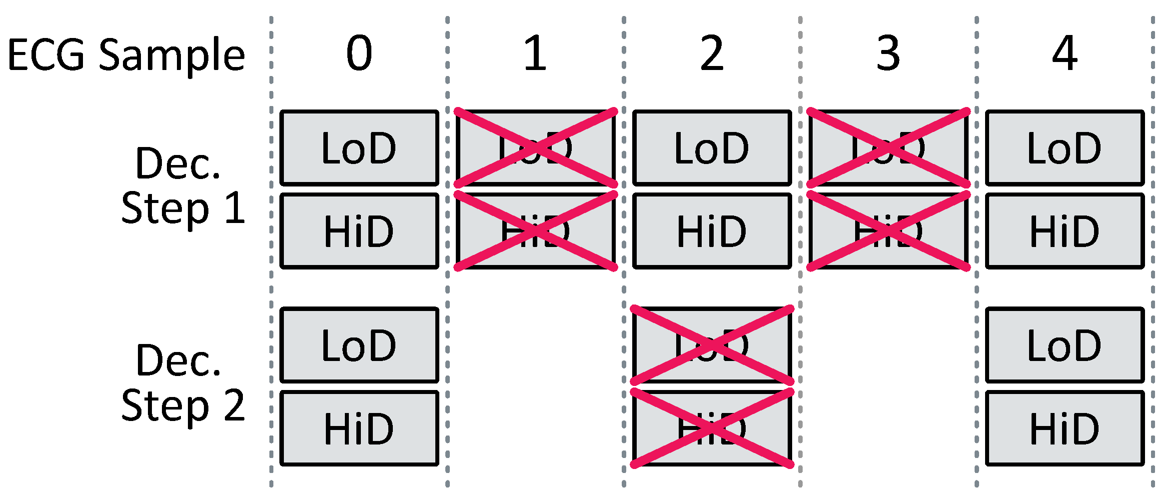
Conventional FWT implementation involves numerous redundant computations due to up- and downsampling operations. During a downsampling operation, one sample out of two samples is removed. Rather than computing an FIR filter output for each new input and subsequently discarding half of the results, we opted to compute an FIR filter output only once for every two inputs, thereby reducing the number of operations by two for the decomposition step.
Figure 7 and
Figure 8 illustrate this scheme for an FWT of depth 2.
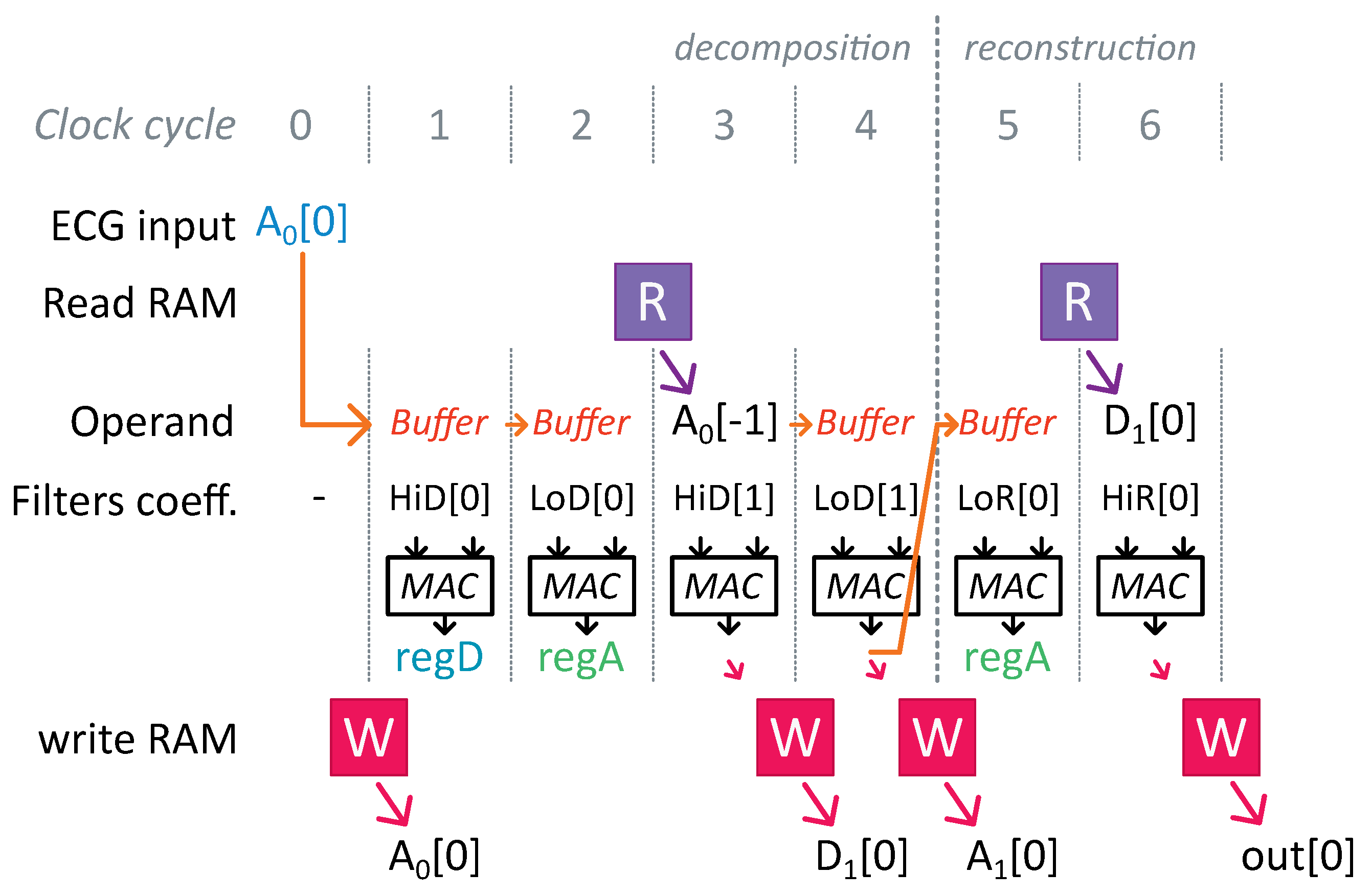
Additionally, a zero was inserted between each signal sample during an upsampling operation. Therefore, during an FIR filter operation in the reconstruction step, half of the multiplications involved a zero operand, meaning that these samples did not affect the final result. By skipping these operations, we further reduced the computation cost.
Furthermore, the LoD and HiD filters used the same input values in the FWT. We interleaved the computations required for an LoD and a HiD filter of the same level to prevent repeated readings of the same value from the RAM. Two registers, and , were incorporated into the MAC unit to simultaneously store intermediate results for both filtering operations.
Finally, the sequence of decomposition and reconstruction steps often necessitated the immediate utilization of a computed result. A forwarding path was implemented in the MAC unit to eliminate the need to wait for one clock cycle to read a value just written in memory.
Figure 9 illustrates optimizations associated with upsampling and memory accesses for an FWT of depth one and two-coefficient FIR filters. The notations used correspond to those in
Figure 4, with
representing the current ECG sample received.
4.3. Baseline Wandering Removal Strategy
Many methods to remove baseline wandering have already been studied and compared [
2,
24]. The simplest one involves setting the appropriate wavelet transform components to zero. Since BW noise predominantly comprises low frequencies, we nullified the
coefficients. To target higher frequencies for filtering, we decreased the depth of the FWT, thereby extending the upper frequency bound of
. This approach offered the advantage of being very straightforward to implement. This method provided encouraging results according to [
2] for the lowest complexity. Furthermore, based on their metrics, this method introduced less distortion than filtering wavelet coefficients. Further, each time an FWT was computed, the approximation coefficient
was set to zero during reconstruction.
4.4. Optimizing Architecture Parameters
The selected architecture involved several parameters that rendered it adaptable to each mother wavelet, enabling area, power consumption, and noise elimination optimization. These parameters included the precision of fixed-point arithmetics utilized in the MAC unit, the precision employed in the ROM and RAM, and the depth of the wavelet transform.
From now on, we denote as the number of FIR filter coefficients, as the depth of the wavelet transform, as the length of the fractional part used to store FIR filter coefficients in ROM, as the size of the data words used in memory, and as the frequency of the system clock. is itself decomposed into an integer part and a fractional part ( and ).
The frequency
and the logic consumption were correlated with the maximum number
of MAC operations executed between two ECG samples. From the architecture and choices made in
Section 4.2, we computed
Hence, it was advisable to opt for a depth that was as shallow as feasible and select a mother wavelet with FIR filters comprising few coefficients. This strategy aimed to restrict the system’s operating frequency and minimize the power consumption of the logic part.
The number of words
required in RAM was associated with the same parameters, as per the following equation:
The term on the right side of the addition was associated with the implementation of the necessary resynchronization (refer to Equation (
1)). Therefore, we encountered once more an exponential dependency on the depth of the wavelet transform, highlighting the significant impact of this parameter on memory size. That is why choosing a minimal depth was imperative to constrain memory consumption and size.
The sole constraint in this optimization came from the distortion of the ST segment. This distortion imposed both a minimum precision and a minimum depth. Specifically, ST segment distortion at the system output correlated with errors introduced by the over-approximation of calculations or baseline removal that eliminated components containing ST segment information.
The optimization process followed a structured sequence. Initially, the precision of the coefficients and calculations was very high and the number of levels was also very high. Then, Algorithm 1 was executed in Python 3.12.5 to find the minimum value for each parameter. The precision of the calculations was determined first, followed by the accuracy of the data in memory and, finally, the depth of the wavelet transform.
| Algorithm 1 FWT Parameter Optimization Algorithm |
Choose one wavelet in the list
Calculate the FWT and ST segment distortion
while ST segment distortion below threshold do
Calculate the FWT and ST segment distortion
end while
while ST segment distortion below threshold do
Calculate the FWT and ST segment distortion
end while | while ST segment distortion below threshold do
Calculate the FWT and ST segment distortion
end while
while ST segment distortion below threshold do
Calculate the FWT and ST segment distortion
end while
Calculate the FWT and the SDR |
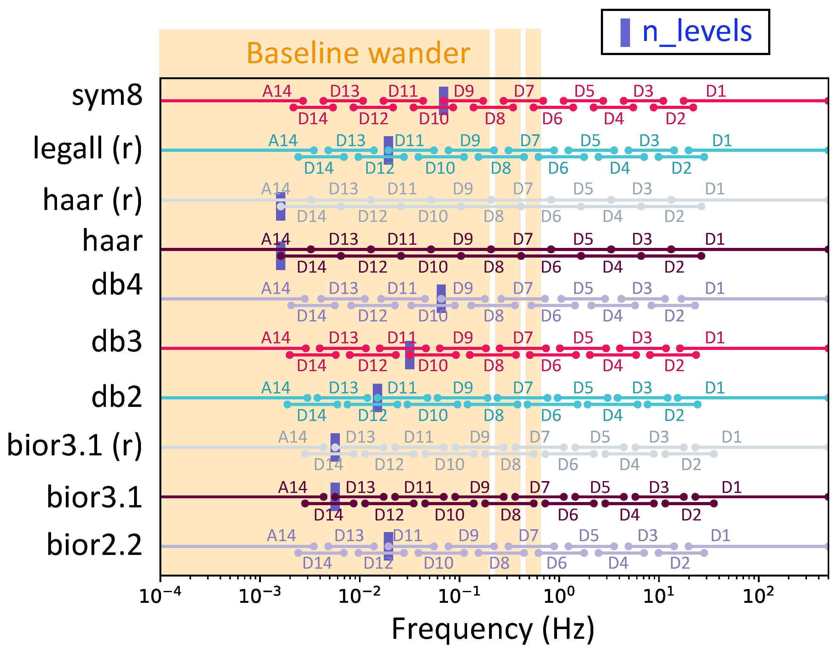
Table 1 presents the values attained for these parameters alongside the corresponding distortion achieved. The SDR mentioned was measured at the output for a noiseless input signal. First, we could observe variability in the optimal wavelet decomposition level (
) under our constraint. This reflected the fact that the selected wavelets had different cutoff frequencies.
Figure 10 shows the corresponding bands for each optimized wavelet and the baseline wander band. The cutoff frequency alone was not sufficient to filter the baseline without eliminating the ST segment. The mathematical properties of the wavelet also played a role. Indeed, it made sense that the higher the filter order, the steeper the transition band and, thus, the more effective the filtering.
4.5. Practical Implementation and Performance Measurement Flow
The architecture was first simulated using a Python script. Then, it was transcribed into VHDL. We ensured consistency across the Python script, VHDL code, and post-layout simulations by meticulously modeling issues such as overflows and underflows in the Python script. This way, we could profit from the significantly faster execution of Python simulations compared to VHDL simulations to realize extended measurements of over a thousand heartbeats. This approach enabled reliable distortion measurements and noise elimination evaluations.
We opted for XFAB
m CMOS technology to implement the architecture. The RAM utilized was a low-power IP sourced from XFAB. VHDL code simulation was conducted using Xcelium software (version 21) from the Cadence suite. Synthesis was executed using Genus software (version 21), providing insights into the required number of logic gates. Then, the layout design was realized using Innovus, which gave the necessary circuit area.
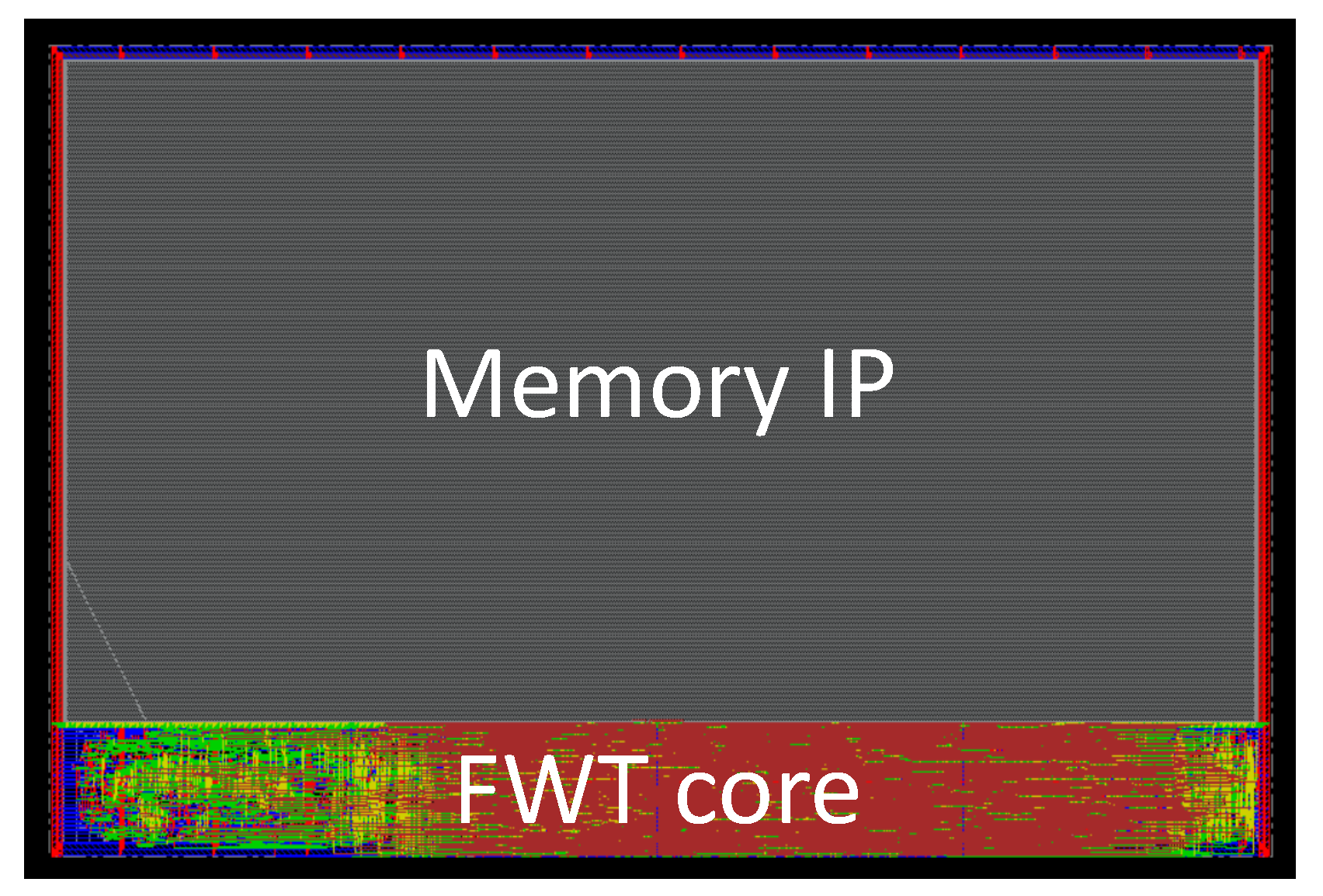
Figure 11 depicts an illustrative layout example for the db3 wavelet. Finally, post-layout simulations were conducted with Xcelium to estimate the circuit’s power consumption.
5. Results and Discussions
The architecture proposed in the preceding section aims to address two challenges. The first is processing ECG signals and filtering baseline wandering (BW) noise without inducing ST segment distortion, as mandated by the IEC standard. The second is the selection of the most suitable mother wavelet for integrated forward wavelet transform (FWT) concerning power consumption and area.
We chose to use the ST segment distortion as a constraint in parameter optimization. Hence, we ensured that ST segment distortion always remained below the thresholds set by the IEC standard.
This section presents the results of optimization for each wavelet configuration. Then, it compares the optimal outcomes for each wavelet to determine which mother wavelet is most suitable for cardiac ischemia monitoring. This involves selecting the wavelet that meets the IEC distortion criterion while exhibiting the lowest power consumption, area requirements, and optimal BW removal.
Finally, it compares the performance of the optimal wavelet with the existing literature.
5.1. Implemented Configurations
The parameters outlined in
Table 1 depict the optimal configurations for each wavelet. One can see that some wavelets’ performances stand out.
Firstly, it was observed that the bior3.1 wavelet and its rational version degraded the SDR. This indicated that the implemented filtering method exacerbated noise instead of mitigating BW. Furthermore, examining the output obtained for a noise-free ECG revealed that the BW removal technique introduced low-frequency variations into the signal. Consequently, it was determined that our noise reduction strategy was unsuitable for the bior3.1 wavelet. As a result, this wavelet was excluded from further analysis in this study.
Moreover, the Haar wavelet and its rational version failed to pass the ST segment slope criterium with a depth lower than 14, the upper limit we fixed for our implementations. However, we conserved them for the rest of this study as a reference.
Finally, we decided to take some margin on the depth for several mother wavelets to improve their SDR performances and make their distortion performances more robust.
We also chose to reduce the number of distinct memory configurations to ease the implementation and allow the reuse of a few memory IPs. A memory size discretization step of 8 k words was adopted and the data word sizes were adjusted to minimize the number of different values. These modifications were executed while ensuring that performance regarding ST segment distortion did not deteriorate.
Table 2 illustrates the implemented configurations.
5.2. Post-Layout Result
Table 3 presents the post-layout results.
The Signal-to-Noise Ratio Improvement (SNRI) was calculated in Python utilizing an input signal sourced from the IEC standard, with baseline wandering (BW) noise acquired from the MIT-BIH database. The input SNR was set to 0 dB. Performance metrics in terms of power consumption differentiated between the RAM and the logic part consumptions.
The best performance in terms of noise removal was consistently observed for configurations with the smallest depths. This outcome was anticipated since, with the noise reduction method employed, a shallower fast wavelet transform (FWT) resulted in a higher proportion of low-frequency noise elimination. Conversely, wavelets requiring greater depths, such as the Haar wavelet, exhibited minimal noise reduction capabilities.
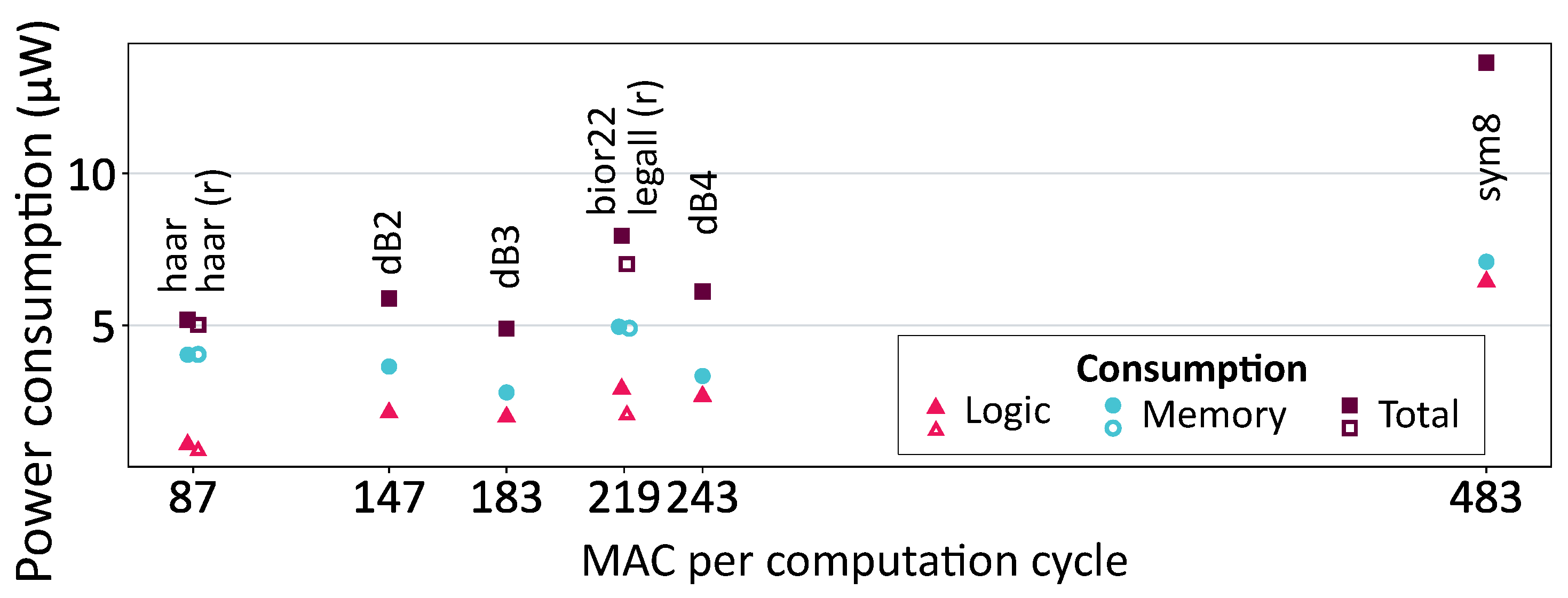
The number of operations per computation cycle directly influenced the power consumption of the logic component. This relationship is illustrated in
Figure 12.
In this figure, hollow markers correspond to wavelets with rational coefficients, characterized by lower and less complex Multiply–Accumulate (MAC) units. While the difference in logic power consumption between Haar and Haar (r) was negligible, a more substantial difference was observed between bior2.2 and LeGall, which had the same number of FIR filter coefficients. As reducing the complexity of the MAC unit reduced its consumption per operation, rational FIR filters’ coefficients were more interesting for a greater number of operations performed.
However, this optimization of logic consumption held little significance in our context, given the predominant impact of memory consumption, which accounted for 50% to 80% of the total power consumption. Memory consumption was influenced by both the size of the implemented memory (static consumption) and its utilization (dynamic consumption). For instance, despite having the lowest logic consumption and fewer memory accesses, the Haar wavelet consumed more than the db3 wavelet due to a larger amount of implemented memory.
The highest total consumption was observed for the sym8 wavelet. Its lengthy FIR filters necessitated numerous operations, resulting in high logic consumption. It also exhibited substantial memory consumption as many FIR filter coefficients led to more memory accesses. This emphasized the importance of selecting a simple mother wavelet with a reduced number of FIR filter coefficients.
The db3 wavelet emerged as the optimal choice, striking the best trade-off among various performance metrics in our context. It had the lowest power consumption at W, the smallest area at mm2, and a respectable SNRI of dB. In the subsequent section, this wavelet is compared with the existing literature.
5.3. Justification of the Chosen Architecture
As presented in
Section 4.1, the chosen approach was one where from a certain wavelet depth, the “processor-based” architecture would optimize the resource usage on the chip. Let us verify that choice by considering the dB3 wavelet with its associated hyperparameters we obtained and including post-layout simulations. According to Equation (
5), and if we include other registers for temporary results, that wavelet requires a total internal memory of 5188 words of 20 bits (including 5065 for delays realization). Had we implemented a conventional architecture, the delays at different depths would ideally have been handled using FIFOs due to their efficiency. However, such IP blocks are not available in the target technology. As a result, the memory would have had to be implemented using registers (e.g., flip-flops). A quick estimate based on the technology characteristics yields an area of approximately
mm
2. This means that the area of the memorizing elements in a conventional architecture would be much more than the total area of our architecture (
mm
2). This demonstrates the relevance of our architectural approach.
5.4. Comparisons with the Literature
To the best of our knowledge, no studies have investigated the impact of mother wavelet choice on the performance of an integrated circuit measuring electrocardiogram (ECG) signals while considering ST segment distortion. Most systems in the literature focus on ECGs in general or cardiac arrhythmias, rarely considering the distortion of medical information. Furthermore, the few articles addressing ECG distortion utilize classic signal processing metrics such as mean squared error (MSE), which are less pertinent for ischemia detection. Nevertheless, we position our work in relation to other articles on related applications.
Table 4 summarizes the comparison.
A theoretical study by the authors of [
2] investigated the impact of baseline wander removal techniques on the ST segment. It employed less stringent constraints than the IEC standard. However, it indicated that an FWT of depth nine was required for the same BW filtering technique as ours. This study aligns with ours on the significant depth needed when considering distortion constraints on the ST segment. The depth was much shallower for all the other articles, particularly in integrated FWT implementations.
Studies [
10,
24] investigated the noise removal performance of wavelet transform. The former utilized an original “Farras” wavelet and compared threshold-based methods on the wavelet transform coefficients to determine the one achieving the best Signal-to-Noise Ratio (SNR) improvement for various noise types. The latter implemented adaptive filtering using wavelet transform to estimate and remove noise. These techniques are more complex than setting coefficients to zero but are not impractical for integrated systems. They achieved SNR improvements of 11 to 15 dB for baseline wander noise, up to 6 times better than the improvement obtained with our db3 wavelet implementation. This comparison suggests potential ways to improve our architecture, such as comparing the gain in SNR improvement achieved by implementing a more complex noise elimination method against the potential additional cost in area and power consumption. Moreover, a more complex method might better suit the bior3.1 wavelet.
The results of FWT chip measurements presented in [
16,
20] allow us to compare our performance in area and power consumption. With FWT depths of 4, these two architectures exhibited significantly lower area or power consumption than those obtained in our work, especially considering that these systems integrated not only an FWT but also algorithms performing peak detection [
16] and even embedded diagnostics [
20]. Needing a depth of 10 to meet the distortion requirements for the ST segment, higher power consumption was inevitable. But, thanks to this exploration, we were able to achieve the optimal possible consumption while complying with the IEC standard in XH018 180 nm technology. Thus, a consumption of 4.89 µW was obtained, which is still viable for a battery-powered system.
This comparison highlights the significant impact of the distortion constraint through the additional cost associated with the substantial depth required for the FWT.
6. Conclusions
This article introduced a configurable fast wavelet transform (FWT) architecture designed to address the issue of distortion in the ST segment. Distortion is considered acceptable for cardiac ischemia monitoring if it is lower than the thresholds specified by the IEC standard for electrocardiographs. The architecture enabled a comparative analysis of ten mother wavelets based on their performance in power consumption, area efficiency, medical information distortion, and baseline wandering removal.
This FWT implementation, employing a simple baseline wandering removal strategy—setting wavelet decomposition coefficients to zero—necessitates more than ten decomposition levels to verify the distortion criteria. Therefore, numerous computations and a large RAM are required. The choice of mother wavelet significantly influences FWT implementation performance: an appropriate wavelet reduces the required FWT depth, enhances BW removal efficacy, and reduces surface area and power consumption.
Among the ten configurations evaluated, db3 emerged as the best trade-off, with a power consumption of W, an area of mm2 in XH018 180 nm technology, an SNR improvement of dB for baseline wander noise removal, and an acceptable ST segment distortion according to the IEC standard.
Admittedly, the achieved power consumption and area were higher than those of most state-of-the-art integrated ECG chips. However, this was due to the fact that we did not address the same application. ST segment monitoring for ischemia detection imposes stringent requirements in terms of signal integrity, which, in turn, necessitates a significantly higher number of decomposition levels compared to other ECG-related applications. Moreover, when compared to the estimated area of a conventional architecture using registers to implement delays, the achieved area is significantly more efficient.
To the best of our knowledge, this work represents the first study of an embedded integrated system specifically designed for continuous ST segment monitoring in ECG signals for ischemia detection. This preliminary investigation demonstrates the feasibility of on-chip ST segment analysis, paving the way for fully integrated ischemia monitoring solutions. A future task will be to implement automatic segmentation, automatic embedded measurements of ST segment deviation in terms of both offset and slope, and, finally, classification to determine whether ischemia is present or not.
Author Contributions
Conceptualization, B.G., C.L.-P., E.A.-M., G.S. and P.B.; methodology, B.G.; software, B.G.; validation, B.G.; formal analysis, B.G.; investigation, B.G., C.L.-P., E.A.-M., G.S. and P.B.; resources, B.G. and P.B.; data curation, B.G. and C.L.-P.; writing—original draft preparation, B.G. and C.L.-P.; writing—review and editing, B.G., C.L.-P. and E.A.-M.; visualization, B.G., C.L.-P. and E.A.-M.; supervision, C.L.-P. and P.B.; project administration, P.B.; funding acquisition, C.L-P. and P.B. All authors have read and agreed to the published version of the manuscript.
Funding
This research received no external funding.
Data Availability Statement
The original contributions presented in this study are included in the article. The source codes that generated the results are not available, as they are part of an ongoing project.
Acknowledgments
The authors would like to thank Koskas of Hôpital de la Pitié-Salpêtrière, Paris, for his valuable medical insights.
Conflicts of Interest
The authors declare no conflicts of interest.
References
- World Health Organization. The Top 10 Causes of Death; World Health Organization: Geneva, Switzerland, 2020. [Google Scholar]
- Lenis, G.; Pilia, N.; Loewe, A.; Schulze, W.H.W.; Dössel, O. Comparison of Baseline Wander Removal Techniques considering the Preservation of ST Changes in the Ischemic ECG: A Simulation Study. Comput. Math. Methods Med. 2017, 9295029. [Google Scholar] [CrossRef]
- IEC 60601-2-25; Medical Electrical Equipment—Part 2–25: Particular Requirements for the Basic Safety and Essential Performance of Electrocardiographs. IEC: Geneva, Switzerland, 2011.
- Guénégo, B.; Lelandais-Perrault, C.; Avignon-Meseldzija, E.; Sou, G.; Bénabès, P. Design of an ECG Front-End Considering ST Segment Distortion. In Proceedings of the 2023 IEEE 14th Latin America Symposium on Circuits and Systems (LASCAS), Quito, Equador, 27 February–3 March 2023; pp. 1–4. [Google Scholar] [CrossRef]
- Pan, J.; Tompkins, W.J. A Real-Time QRS Detection Algorithm. IEEE Trans. Biomed. Eng. 1985, BME-32, 230–236. [Google Scholar] [CrossRef]
- Xu, X.; Suo, Y.; Zhou, P.; Han, X.; Cai, Q.; Wang, G.; Lian, Y.; Zhao, Y. A 2.67GΩ 454nVrms 14.9μW Dry-Electrode Enabled ECG-on-Chip with Arrhythmia Detection. In Proceedings of the 2023 IEEE Custom Integrated Circuits Conference (CICC), San Antonio, TX, USA, 23–26 April 2023; pp. 1–2, ISSN 2152-3630. [Google Scholar] [CrossRef]
- Bauer, F.C.; Muir, D.R.; Indiveri, G. Real-Time Ultra-Low Power ECG Anomaly Detection Using an Event-Driven Neuromorphic Processor. IEEE Trans. Biomed. Circuits Syst. 2019, 13, 1575–1582. [Google Scholar] [CrossRef]
- Dekimpe, R.; Bol, D. ECG Arrhythmia Classification on an Ultra-Low-Power Microcontroller. IEEE Trans. Biomed. Circuits Syst. 2022, 16, 456–466. [Google Scholar] [CrossRef]
- Kumar, A.; Ranganatham, R.; Kumar, M.; Komaragiri, R. Hardware Emulation of a Biorthogonal Wavelet Transform-Based Heart Rate Monitoring Device. IEEE Sens. J. 2021, 21, 5271–5281. [Google Scholar] [CrossRef]
- Mathuria, R.; Potla, V.V.K.; Prajapati, P.; Gupta, S.; Kakkireni, N.; Darji, A. Hardware Co-Simulation of an Efficient Adaptive Filter based ECG Denoising System with Inbuilt Reference Generator. In Proceedings of the 2022 IEEE Region 10 Symposium (TENSYMP), Mumbai, India, 1–3 July 2022; pp. 1–6. [Google Scholar] [CrossRef]
- Zou, Y.; Han, J.; Xuan, S.; Huang, S.; Weng, X.; Fang, D.; Zeng, X. An Energy-Efficient Design for ECG Recording and R-Peak Detection Based on Wavelet Transform. IEEE Trans. Circuits Syst. II Express Briefs 2015, 62, 119–123. [Google Scholar] [CrossRef]
- Loh, J.; Wen, J.; Gemmeke, T. Low-Cost DNN Hardware Accelerator for Wearable, High-Quality Cardiac Arrythmia Detection. In Proceedings of the 2020 IEEE 31st International Conference on Application-specific Systems, Architectures and Processors (ASAP), Manchester, UK, 6–8 July 2020; pp. 213–216. [Google Scholar] [CrossRef]
- Ieong, C.I.; Mak, P.I.; Lam, C.P.; Dong, C.; Vai, M.I.; Mak, P.U.; Pun, S.H.; Wan, F.; Martins, R.P. A 0.83-μW QRS Detection Processor Using Quadratic Spline Wavelet Transform for Wireless ECG Acquisition in 0.35-μm CMOS. IEEE Trans. Biomed. Circuits Syst. 2012, 6, 586–595. [Google Scholar] [CrossRef]
- Min, Y.J.; Kim, H.K.; Kang, Y.R.; Kim, G.S.; Park, J.; Kim, S.W. Design of Wavelet-Based ECG Detector for Implantable Cardiac Pacemakers. IEEE Trans. Biomed. Circuits Syst. 2013, 7, 426–436. [Google Scholar] [CrossRef] [PubMed]
- Han, J.; Zhang, Y.; Huang, S.; Chen, M.; Zeng, X. An Area-Efficient Error-Resilient Ultralow-Power Subthreshold ECG Processor. IEEE Trans. Circuits Syst. II Express Briefs 2016, 63, 984–988. [Google Scholar] [CrossRef]
- Chen, Y.H.; Lu, C.W.; Chen, S.W.; Tsai, M.H.; Lin, S.Y.; Chen, R.S. VLSI Implementation of QRS Complex Detector Based on Wavelet Decomposition. IEEE Access 2022, 10, 134758–134768. [Google Scholar] [CrossRef]
- Hampton, J.R. The ECG Made Easy; Elsevier Health Sciences: London, UK, 2013. [Google Scholar]
- Goldberger, A.L.; Amaral, L.A.N.; Glass, L.; Hausdorff, J.M.; Ivanov, P.C.; Mark, R.G.; Mietus, J.E.; Moody, G.B.; Peng, C.K.; Stanley, H.E. PhysioBank, PhysioToolkit, and PhysioNet: Components of a New Research Resource for Complex Physiologic Signals. Circulation 2000, 101, e215–e220. [Google Scholar] [CrossRef] [PubMed]
- Mallat, S. A Wavelet Tour of Signal Processing; Chapter Wavelet Bases; Academic Press: Boston, MA, USA, 2009; pp. 298–311. [Google Scholar] [CrossRef]
- Liu, X.; Zhou, J.; Yang, Y.; Wang, B.; Lan, J.; Wang, C.; Luo, J.; Goh, W.L.; Kim, T.T.H.; Je, M. A 457 nW Near-Threshold Cognitive Multi-Functional ECG Processor for Long-Term Cardiac Monitoring. IEEE J. Solid-State Circuits 2014, 49, 2422–2434. [Google Scholar] [CrossRef]
- Brechet, L.; Lucas, M.F.; Doncarli, C.; Farina, D. Compression of Biomedical Signals With Mother Wavelet Optimization and Best-Basis Wavelet Packet Selection. IEEE Trans. Biomed. Eng. 2007, 54, 2186–2192. [Google Scholar] [CrossRef] [PubMed]
- Milosavljević, N.; Petrovic, A. ST Segment Change Detection by Means of Wavelets. In Proceedings of the 2006 Seminar on Neural Network Applications, Belgrade, Serbia, 25–27 September 2006; pp. 137–140. [Google Scholar]
- Daubechies, I.; Sweldens, W. Factoring wavelet transforms into lifting steps. J. Fourier Anal. Appl. 1998, 4, 247–269. [Google Scholar] [CrossRef]
- el B’Charri, O.; Rachid, L.; Elmansouri, K.; Abenaou, A.; Jenkal, W. ECG signal performance de-noising assessment based on threshold tuning of dual-tree wavelet transform. BioMed. Eng. OnLine 2017, 16, 26. [Google Scholar] [CrossRef] [PubMed]
| Disclaimer/Publisher’s Note: The statements, opinions and data contained in all publications are solely those of the individual author(s) and contributor(s) and not of MDPI and/or the editor(s). MDPI and/or the editor(s) disclaim responsibility for any injury to people or property resulting from any ideas, methods, instructions or products referred to in the content. |
© 2025 by the authors. Licensee MDPI, Basel, Switzerland. This article is an open access article distributed under the terms and conditions of the Creative Commons Attribution (CC BY) license (https://creativecommons.org/licenses/by/4.0/).


 ,
, 


