Review

Prospective Review of Magneto-Resistive Current Sensors with High Sensitivity and Wide Temperature Range

School of Integrated Circuits, Jiangnan University, Wuxi 214122, China
*
Author to whom correspondence should be addressed.
J. Low Power Electron. Appl. 2024, 14(3), 43; https://doi.org/10.3390/jlpea14030043
Submission received: 18 June 2024 / Revised: 13 August 2024 / Accepted: 14 August 2024 / Published: 19 August 2024

Abstract

:
Current sensors play a vital role in power systems, industrial production, smart devices and other fields, which can provide critical current information in the systems for the safety and efficiency managements. The development of magneto-resistive effect technology in recent years expedites the research process of the current sensors in industrial-level applications. In the review, starting with the development status of the current sensors, the physical mechanisms of the relevant magneto-resistive effects and their early applications as the current sensors are introduced. Several design methods of the magnetic sensors, as well as their merits and shortcomings, are summarized. The performance parameters of the magnetic sensors based on AMR, GMR, TMR and Hall effects are reviewed, including the front-end amplification circuits and conditioning circuits. The industrial applications of the current sensors in the fields of automobiles and photovoltaic inverters are enumerated. The criterions for the current sensors to be used in different scenarios are discussed. In the future, it is imperative to continue the research and development of novel current sensors in order to satisfy the increasingly stringent demands of the industrial developments, in terms of the performance, cost and reliability of the current sensors.

1. Introduction

With the fast and everlasting development of integrated circuit and semiconductor technologies as the information age nowadays, electrical current is one of the most important parameters to illustrate and control in the smart information system. In this way, the current sensor, as a device specialized in measuring the flow direction and the value of the electrical current, plays a crucial role in many fields, such as the smart grid, new energy vehicles and aerospace, etc. Its accurate measurement and real-time monitoring function ensure the stable and efficient operation of the smart system. With the continuous development in the smart power grid, the requirement on the current sensor is shifted from the traditional simple measurement into the smart ones, with the merits of large a measuring range, compact size, high precision, high sensitivity and low susceptibility to temperature drift, etc., [1]. The development path of the current sensor is schematically shown in Figure 1 [2].
Traditionally, the current sensors applied in the power grid include a shunt, current transformer, Rogowski coil, etc. The shunt sensor is actually a precise resistor with a small resistance value. It is connected in series in the current loop to measure the voltage difference between its two ends and the current value can be obtained based on Ohm’s law. The current transformer is based on Faraday’s Law of Electromagnetic Induction. With the measured current flowing through the conductor changes, an induced electromotive force would be generated in the secondary coil of the transformer, which is proportional to the measured current in the conductor. The Rogowski coil sensor is also based on Faraday’s Law of Electromagnetic Induction. Its working principle involves inducing an AC voltage signal in the coil that is proportional to the derivative of the current. The current in the conductor can be restored through an integral calculation.
For the above-mentioned traditional current sensors, they all have the advantages of a simple structure and low cost. However, they also have obvious disadvantages, such as a large size, high power consumption, low sensitivity and poor anti-interference capabilities, etc., [3]. The novel current sensors, based on the magneto-resistive effect, Hall effect, fiber optic principle, etc., can effectively reduce the size of the sensor, improve the sensitivity and enhance the anti-interference ability. The novel sensors can conduct non-contact measurements, which have a wide range of application prospects in the power grid.
Among them, the current sensor based on the fiber optic principle shows the merits of a wide dynamic range, good corrosion-hardness, simple insulation structure, high measurement sensitivity, easy installation and maintenance, low cost, small size, high safety, etc., [4]. However, the fiber optic current sensor is easily affected by the environment and the failure rate is high due to temperature drift, vibration and other problems [5].
On the other hand, the current sensor based on the magneto-resistive effect, as a new-generation current sensor, began with the discovery of the magneto-resistance effect by the British physicist William Thomson in 1857 [6]. Until now, a variety of magneto-resistive current sensors have been developed, including an AMR (Anisotropic magneto-resistance) sensor based on the anisotropy of the magneto-resistance effect, a GMR (Giant magneto-resistance) sensor based on the giant magneto-resistance effect and a TMR (Tunneling magneto-resistance) sensor based on the tunneling magneto-resistance effect, etc. Currently, the magneto-resistive device can be fabricated at the micrometer level, with the merits of high sensitivity, low power consumption, high integration and a strong anti-interference ability [7,8,9,10]. The Hall effect is another kind of magneto-resistive effect, with an intuitively simple principle and better stability. The Hall sensor has a wider range of application scenarios, including the current measurement and the magnetic field detection, etc., [11].
With the growing industrial requirement for a high-sensitivity and low-power current sensor, innovative technologies for integrating current sensors are emerging. However, the Hall sensor shows a high power consumption and small signal-to-noise ratio (SNR), limiting its further development in the industrial application. In contrast, magneto-resistive sensors, including AMR, GMR, and TMR, have gradually gained more attention from researchers in the field of current sensing with their superior advantages [12]. In the paper, the progress and the applications of the current sensors based on the AMR, GMR, TMR and Hall effects are reviewed.
As shown in Figure 1, besides the Hall sensor and the magneto-resistive sensors, there are other types of current sensors, such as the magneto-electric (ME) sensor and the surface acoustic wave (SAW) sensor, which also have a wide range of prospects for application in the current measurement field. The ME sensor based on a magneto-electric composite can realize a wide range and wide bandwidth for both AC and DC measurements with passive and energy self-pickup characteristics [13]. The SAW sensor is based on the piezoelectric effect, enabling the integration with other circuits and elements. With a specific design and extra magnetic-sensitive material/structure, the change in the magnetic field on the surface can be measured, with the merits of high frequency, high sensitivity, and low power consumption [14]. There are two kinds of SAW sensors, including the magneto-resistive SAW sensor and the magneto-strictive membrane SAW sensor. The magneto-strictive SAW sensor shows good experimental results [15]. However, the strong remanent magnetization and the hysteresis effect of the magneto-strictive film could deteriorate the linearity and lead the hysteresis error [15].
Currently, the detection technology is continuously developing, with recent advancements spanning multiple areas, including the sensor technology and the biosensor technology, with the adoption of new materials. For instance, the novel current sensor with the cutting-edge electronic component and the advanced signal processing technique shows accurate detection with high precision. The biosensor, which combines biology with the sensor technology, can be used to detect the current change inside biological organisms. This technology enables a new possibility for medical diagnostics and artificial intelligence (AI).
The main content of this paper is organized as follows: The principles of the magneto-resistive current sensors are introduced in the second part, which mainly includes the basic principle of the current measurement. In the third part, several main characteristics of the current sensors are introduced, including sensitivity, the operating temperature range, accuracy, and so on. In the fourth part, several major magneto-resistive effects are introduced, including the AMR, GMR, TMR and Hall effects, etc. The amplification circuits, the conditioning circuits and the applications of the current sensors are reviewed in the fifth part. Finally, the conclusions are summarized in the sixth part.

2. Principle and Structure of Magneto-Resistive Current Sensor

The basic structure of the current sensor includes open-loop current sensing, closed-loop current sensing and array current sensing, etc. The open-loop sensor does not require a feedback loop; hence it is named “open-loop”. It is typically used in low-power and high-bandwidth applications. The closed-loop current sensor, on the other hand, incorporates a feedback loop to enhance the measurement accuracy. The closed-loop sensor can generally offer higher precision and better temperature stability. The array-type current sensor, a specialized type of the current sensor, can utilize multiple sensor elements to simultaneously measure the current distributions at various locations. It is typically employed in scenarios requiring high spatial resolution and current distribution analysis. The characteristics of the three structures are shown in Table 1.

2.1. Principle of Magneto-Resistive Current Sensor

According to Biot–Savart’s law, the magnetic field generated by a current-carrying wire at point P in space is:
d B = μ 0 4 π I d l × r r 3 = μ 0 4 π I d l sin θ r 2
where I is the measured current, d l is the line element of I and μ 0 is the vacuum permeability, with a value of 4 π × 10 7 Tm / A .
B = L μ 0 4 π I d l × e r r 2
where L is the integration path and e r the unit vector.
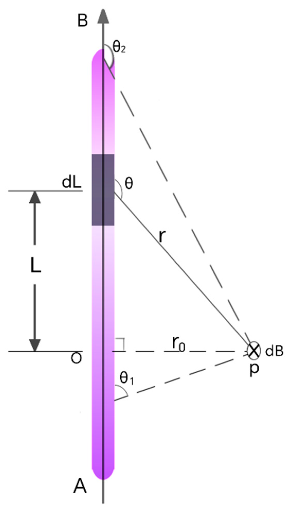
A model of the magnetic field generated by the current-carrying conductor is shown in Figure 2. The measured current flowing inside the current-carrying conductor is denoted as I, the distance between point P and section d l of the conductor in space is r and the perpendicular distance to the current-carrying conductor AB is r 0 . The magnetic field of the current-carrying conductor at point P can be derived based on Equations (1) and (2):
d B = A B μ 0 4 π I d l sin θ r 2
The relationship between L and r 0 is:
L = r 0 cot θ
Both sides can be obtained by differentiating simultaneously:
d l = r 0 d θ s i n 2 θ
This can be obtained by replacing the integral variables in Equation (3):
d B = μ 0 4 π θ 1 θ 2 I sin θ r 0 d θ = μ 0 I 4 π r 0 cos θ 2 cos θ 1
When the length of the current-carrying conductor AB is fixed, the magnitude of the magnetic field at point P is proportional to the current in the conductor. The characteristic of a magneto-resistive current sensor is that there is a linear relationship between the magnetic field and the output voltage. A linear relationship between the sensor’s output voltage and the measured current can be established. This lays the foundation for the basic principle of the magneto-resistive current sensor.

2.2. Open-Loop Current Sensor

The open-loop current sensor shows the simple structure with less power consumption [16]. However, its range is limited by the magnetic saturation in the polymer ring structure. Its accuracy is lower than the others [17,18,19]. The structure of the open-loop current sensor is shown in Figure 3.
The open-loop current sensor mainly consists of a polymagnetic ring, a magnetic sensor and a signal conditioning circuit. The magnetic sensor is placed at the open air gap of the magnetic ring, so that the direction of the sensitive axis coincides with the direction of the air gap’s magnetic field. When the measured current passes through the magnetic ring, the resulting magnetic field is effectively collected by the magnetic ring. Then the magnetic signal is converted into an electrical signal. After signal amplification, zeroing and clarifying the transfer relationship between the current–magnetic field–output voltage, the current to be measured can be indirectly calculated by measuring the output voltage value of the sensor.
The transfer function can be expressed as:
V o u t = K I i n
where V o u t is the output voltage of the sensor, I i n is the measured current and K is the sensitivity constant of the sensor, indicating the proportionality between the output voltage and the input current.
The main role of the polymer ring in Figure 3 is to effectively harvest the magnetic field generated by the measured current to the air gap, thus eliminating the potential impact on the measurement results due to the difference in the position of the wire. The property of the polymer ring material is very important to the performance of the current sensor. Generally, soft magnetic materials with large permeability are suitable for the polymer ring [20,21,22]. A comparison of the properties of common soft magnetic materials is listed in Table 2.

2.3. Closed-Loop Current Sensor

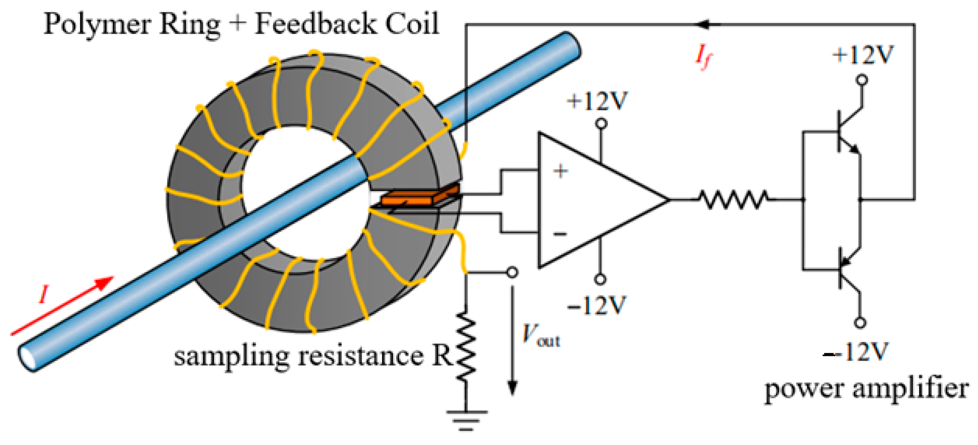
In the closed-loop current sensor, power amplification circuits and feedback coils wrapped around a polymer ring are included. So, compared to the open-loop sensor, the closed-loop current sensor shows a larger size, higher cost and more power consumption [24]. However, the closed-loop current sensor shows higher accuracy and a wider sensing range because the errors in the closed-loop can be automatically compensated. So the polymer ring can be operated in a near-zero flux state [25]. The schematic structure of the closed-loop current sensor is shown in Figure 4.
As shown in Figure 4, the magnetic sensor can generate a voltage signal that is proportional to the measured current. The output voltage signal can be amplified by the power amplifier circuit and then it is fed back to drive the feedback coil. During the driving, a reverse magnetic field inside the magnetic loop is generated, which can be used to offset the magnetic field of the measured current. Once the two magnetic fields are equal, the polymer loop is operated in a near-zero flux state. The current can be calculated by measuring the voltage of the sampling resistor R in the feedback loop. The transfer function of its output voltage can be expressed as:
V o u t = K I i n I b i a s
where V o u t is the output voltage of the sensor, I i n is the measured current, I b i a s is the bias current, which is used to adjust the operating point of the sensor, and K is the sensitivity constant of the sensor.

2.4. Array Current Sensor

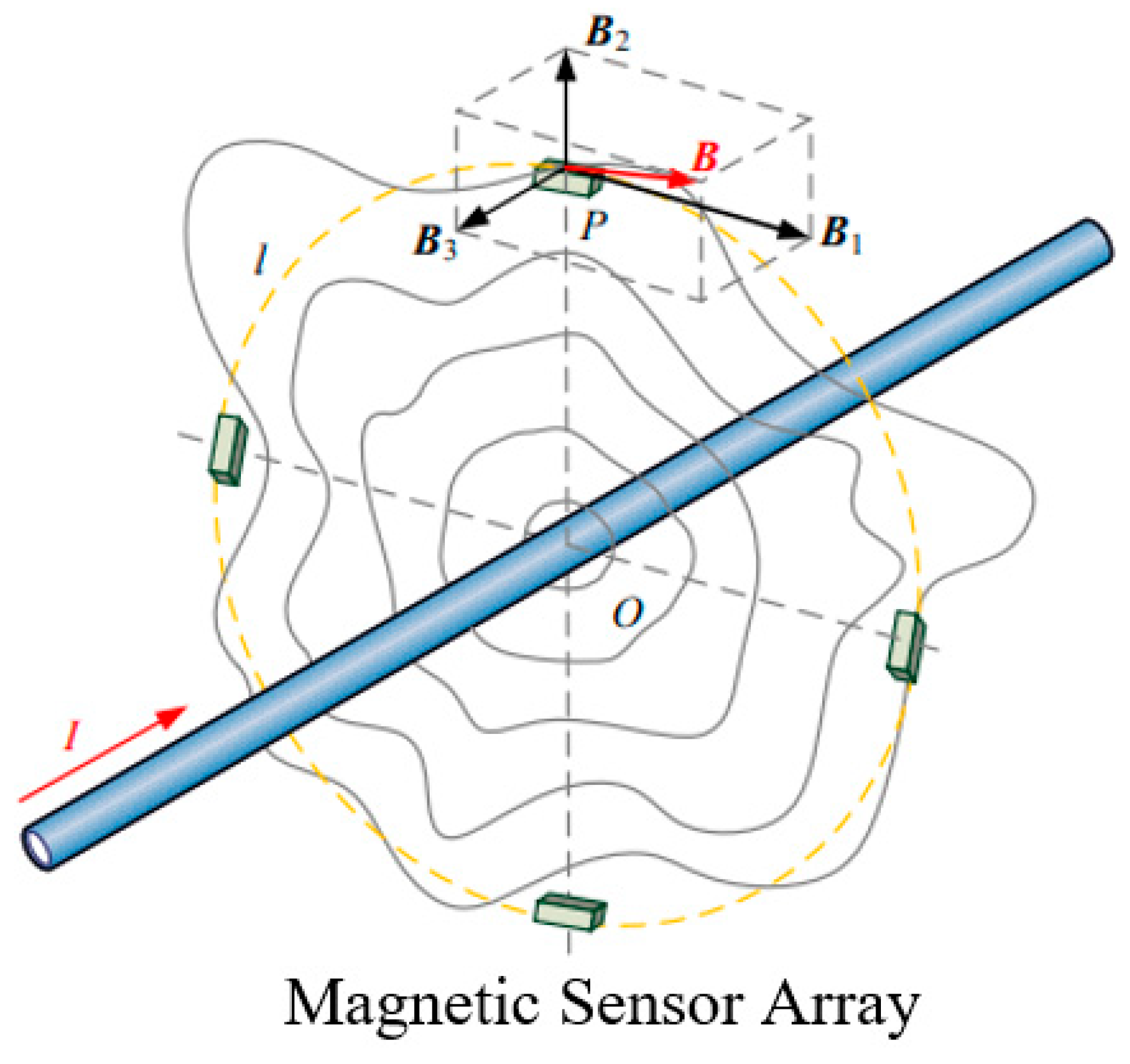
If multiple currents exist in the environment around the measured current, the currents can generate a synthesized magnetic field. In this scenario, a single current sensor could not distinguish them from each other [26]. To improve its accuracy and eliminate the magnetic field interference, the measurement error can be reduced by using multiple sensors assembled in an array structure [27], as shown in Figure 5.
The transfer function of its output voltage can be expressed as:
V o u t = i = 1 N K i I i n i
where V o u t is the output voltage of the sensor, I i n i is the current measured by the ith current sensor, K i is the sensitivity constant of the ith current sensor and N is the number of current sensors in the array.
The accuracy of the array sensor is subject to disturbances caused by the current conductor offsets and the external magnetic fields. The error may be caused by conductor centrifugation, conductor eccentricity and adjacent conductor interference, etc. It can be suppressed by using the sensor array with special algorithmic processing [28]. Figure 6 shows the errors caused by the conductor offset from the array center by external interference currents with different numbers of the adopted magnetic sensors.

3. Characteristic Parameters of Current Sensor

The characteristics of the current sensors are intensely related to the working principle, the structure and the materials of the sensors. For example, in the current sensor based on the magneto-resistance effect, the current through the magnetic field generated by the magneto-resistance element can be indirectly measured. The characteristics of the magneto-resistance current sensor are related to the performance of the magneto-resistance element. Both the structure and the materials of the sensor could affect its sensitivity, temperature stability and other performance parameters.

3.1. Sensitivity

In the current sensor, the sensitivity refers to the degree of response of the sensor’s output signal to the change of the input current. The higher the sensitivity, the more sensitive the sensor is to changes in current. It can be expressed as:
S = Δ V o u t Δ I i n
where S is the sensitivity, Δ V o u t is the change in the output signal and Δ I i n is the change in the input current.
A general adopted approach to improve the sensitivity is to use a magnetic material to concentrate the magnetic field around the sensor [29]. For the magneto-resistive current sensor, to enhance the magnetic field sensitivity of the magnetic reluctance unit, the reluctance rate can be increased. The saturation magnetic field is close to the magnetic field generated by the current, ensuring that the magnetic reluctance unit remains within the linear range during operation, allowing it to produce a linear response to the changes of the external magnetic field. In this way, the sensitivity and the measurement accuracy of the magnetic reluctance unit can be improved. A magneto-resistive current sensor has the characteristic of a high magnetic resistive rate and thus shows higher sensitivity compared to the other traditional current sensors. Carles Navau et al. have also designed a spherical metamaterial shell with anisotropic magnetic properties. When the shell is wrapped around the sensor, magnetic field enhancement can be maintained in transient magnetic fields with frequencies of up to 100 kHz, significantly improving its sensitivity [30].

3.2. Operating Temperature Range

The operating temperature range of the current sensor is affected by several factors, including material properties, packaging, manufacturing processes, etc. The materials in the sensor could be deformed or degraded at high temperature, affecting the sensitivity and the accuracy and rendering it inoperable. There is an increasing demand in modern industry for current sensors that can be operated in a wider range of high-temperature environments, such as those found in automotive, aerospace and other fields. To meet these special requirements, a wider operating temperature range is the key parameter of the current sensor. A magneto-resistive current sensor typically shows a wide operating temperature range, often from −40 °C to 125 °C. Due to the relatively simple operating principle and the good temperature stability of the magneto-resistive current sensor, it exhibits a stable performance and is suitable for both industrial and automotive applications.

3.3. Accuracy

The accuracy of the current sensor is primarily affected by noise interference, with common noises including thermal noise and 1/f noise. High-performance signal conditioning circuits can be used to reduce noise in the output signal and improve accuracy. The magneto-resistive current sensor is a non-contact sensor. This measurement method can reduce external interference and the magneto-resistive current sensor also has high sensitivity, enabling it to detect changes in tiny magnetic fields and thereby accurately measure current levels, improving measurement accuracy.

4. Magneto-Resistance (MR) Effect

The magneto-resistance (MR) effect reveals the principle that the resistance of a material is changed in response to an external magnetic field [31]. The magnitude can be characterized by the magneto-resistance coefficient, MR:
M R = R H R 0 R 0 × 100 % = ρ H ρ 0 ρ 0 × 100 %
where R H and ρ H denote the resistance and resistivity with the applied magnetic field, respectively, H denotes the magnetic field strength and R 0 and ρ 0 denote the resistance and the resistivity when the magnetic field strength is zero.
Based on the magneto-resistive effect, the state of electron motion inside the material is affected by the externally applied magnetic field, which can change the material’s resistance [32]. The magneto-resistive effect can be used to design highly sensitive magnetic field sensors for detecting weak variation of the magnetic field. The effect can also be applied in magnetic storage technology to improve the speed and stability of reading and writing data [33]. The magneto-resistive effect has a wide range of applications in the fields of sensors, data storage and magneto-electronics, etc.

4.1. Anisotropic Magneto-Resistance (AMR) Effect

In ferromagnetic thin-film materials, such as iron and cobalt, their electrical resistance can be changed by the angle between the internal direction of magnetization and the direction of the current [34,35]. This is due to the anisotropy of electron scattering in the d-plane and s-plane regions within the conductor [36]. This is named the anisotropic magneto-resistance (AMR) effect, as shown in Figure 7a.
As shown in Figure 7a, when there is no external magnetic field H, the magnetization direction M is not deflected and the angle θ between the magnetization direction and the current direction is 0°, at which time the resistivity of the film reaches the maximum value. With the increase of the external magnetic field H, the magnetization direction M is deflected, θ starts to increase and the resistivity of the film decreases. When θ is equal to 90°, the resistivity reaches the minimum value, as shown in Figure 7b. The AMR effect in ferromagnetic materials was discovered in 1857 [37].
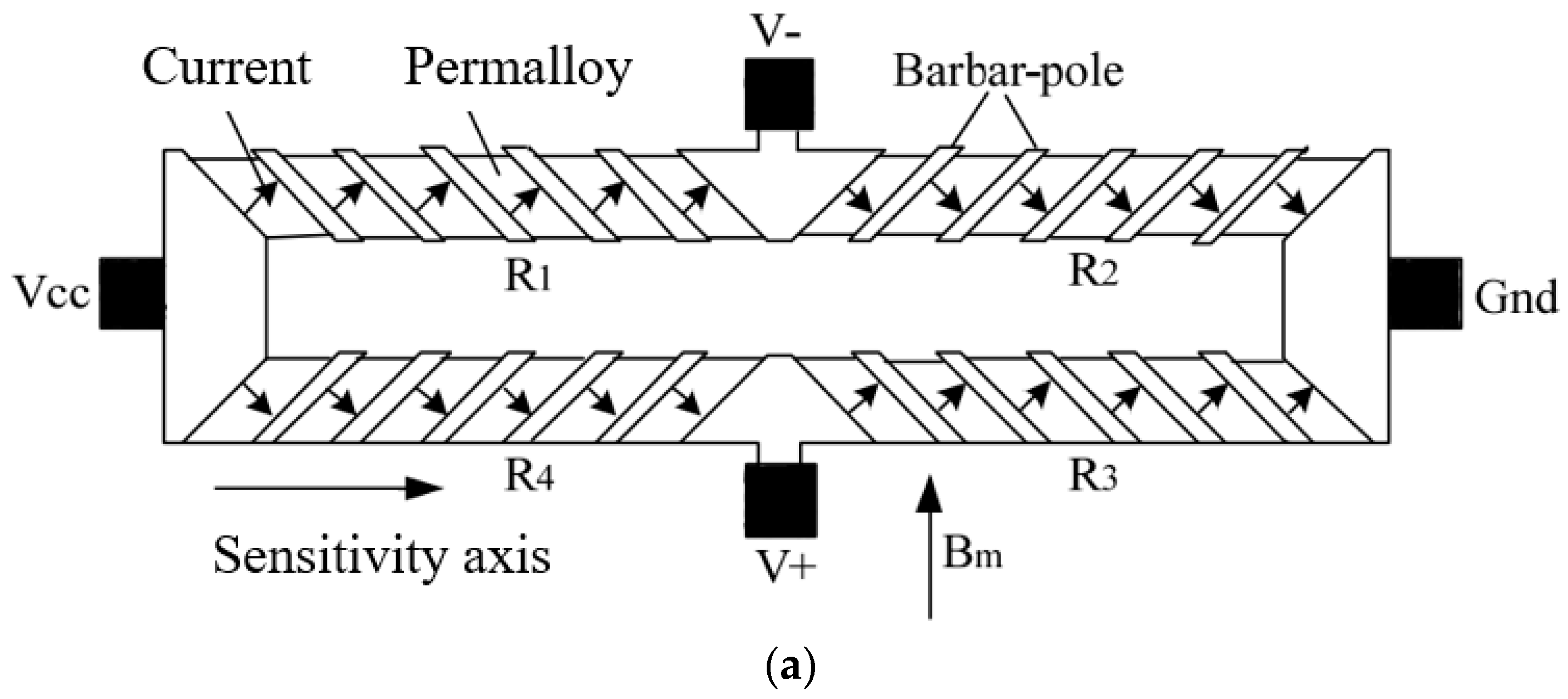
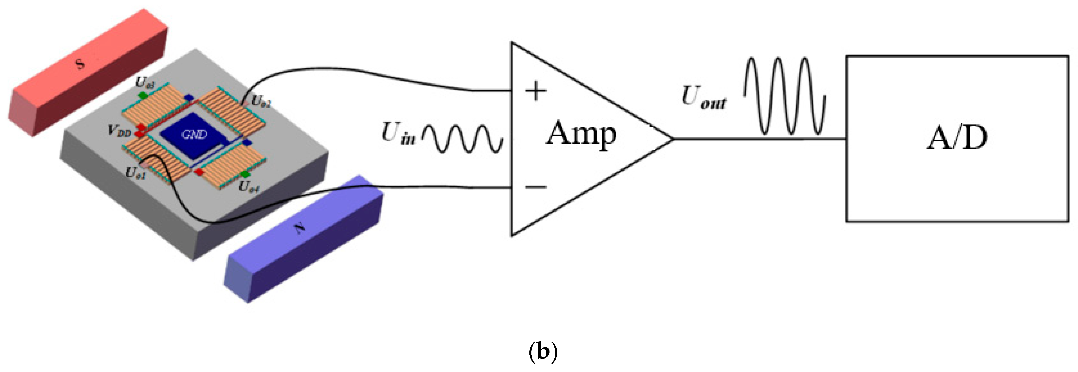
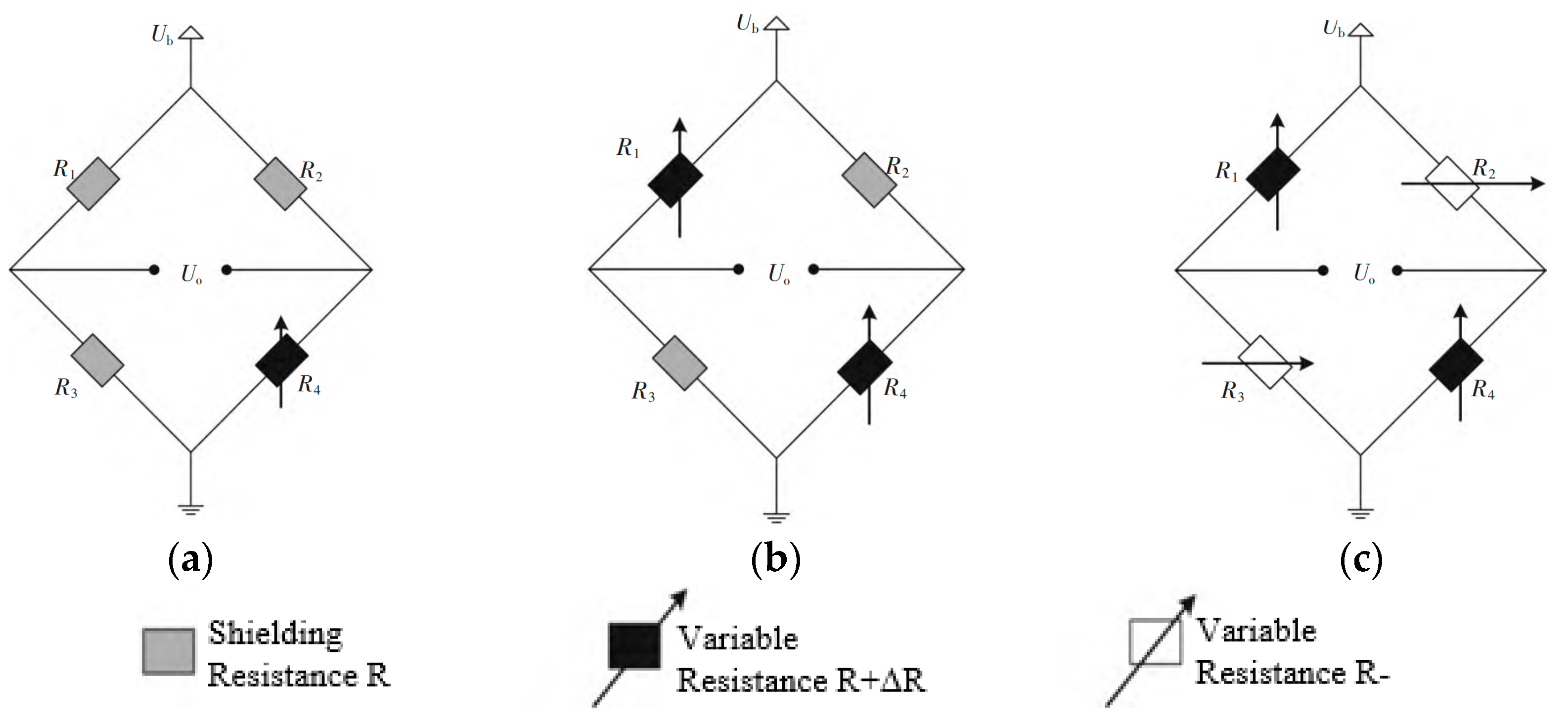
The AMR sensor shows the advantages of a small size, low power consumption and high reliability [38]. Commonly, in the AMR sensor, PoMo alloy magneto-resistive strips based on the Baber pole structure are organized in the structure of a Wheatstone bridge, as shown in Figure 8a. When Bm = 0, R1 = R2 = R3 = R4 = R0. So, the output voltage of the Wheatstone bridge is zero. If Bm is not zero, since the Baber electrode angles of R1 and R4 are the same, both of their resistances are decreased at the same time. Meanwhile, the Baber electrode angles of R2 and R3 are the same, but opposite to those of R1 and R4, so both of their resistances are increased at the same time. So, the output voltage is:
U = V + V = R 0 + Δ R 2 R R 0 Δ R 2 R V C C = Δ R R 0 V C C
The relationship between the resistance variation and the magnetic field can be determined by the voltage magnitude of the Wheatstone bridge [39]. The AMR sensor has differential output voltages, so the output signal should be amplified by an amplifier circuit, as illustrated in Figure 8b.
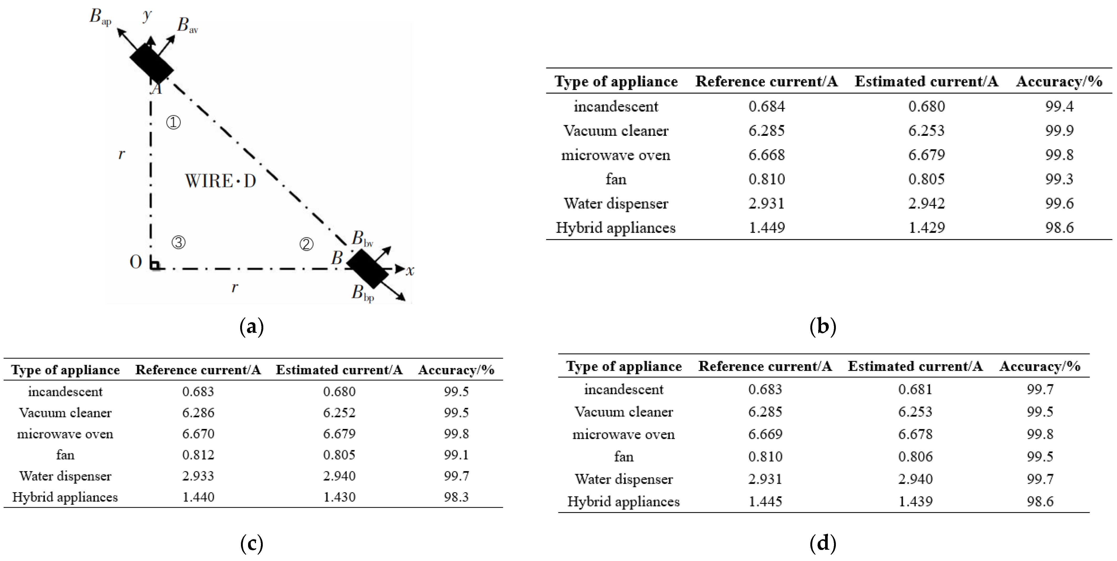
In the 1980s, the AMR sensor was rapidly developed and began to be applied in the field of current measurement. In 2008, Pavel Mlejnek et al. removed the polymer ring and designed an array AMR current sensor, which showed a measurement range of 20 A, linearity of ±0.05% and resolution of 4 mA [40]. Dong Yin et al., in 2018, proposed a current measurement system based on a dual-axis AMR sensor, which can be used to measure concentric conductor currents. Two biaxial magneto-resistive sensors, HMC1022 from HoneyWell [41], were used to design the sensor unit and an isosceles right triangle was constructed from the two sensors placed at points A and B, respectively, and the origin O in the Cartesian coordinate system, modeled as shown in Figure 9a. The final test was performed at three different positions on the sensor unit and the test results are shown in Figure 9b–d. The system can achieve high-accuracy results [41]. Petr Belyakov et al. in 2021 investigated the effect of the polymer ring on the output signal of the current sensor with different conductor positions. It is found that the polymer ring can be used to effectively alleviate the sensitivity and reduce the error caused by the conductor eccentricity. A low-power AMR current sensor is designed, with a frequency of 210 kHz, measuring a range of ±24 A and a conversion factor of up to 4 V/A [42].
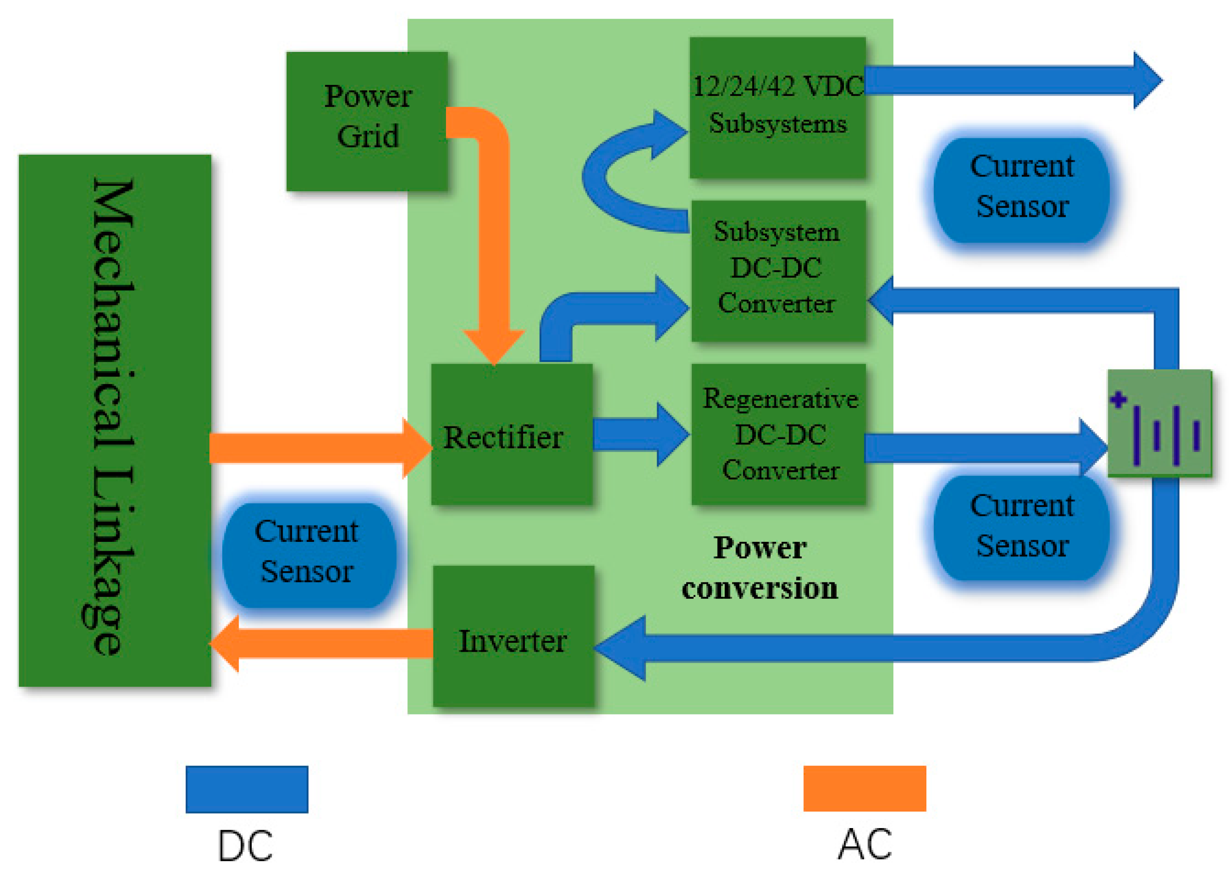
Currently, “smart” products have become a hot topic in the development of electronic systems. In the field of hybrid electric vehicles (HEVs), current sensing is one of the key components in the electronic control system (Figure 10). The inherent isolation of the AMR current sensor makes it suitable to be assembled on both high and low sides of the circuit, significantly improving the overall performance and safety of the circuit. These non-contact current sensors eliminate the power consumption, provide a faster response and reduce the readout time. The offset can be corrected with the active feedback loops. This design provides an important safeguard for the safety and the efficient operation of electric vehicles.
AMR has a relatively good sensitivity, working temperature range and accuracy. In some scenarios where the sensitivity and working temperature range are required, AMR sensors can complete the work stably. Moreover, AMR sensors are designed with only one layer of magnetic film without additional ferromagnetic rings, resulting in better stability [43]. As current sensors continue to evolve, the research on AMR is likely to remain a source of considerable interest.

4.2. Giant Magneto-Resistance (GMR) Effect
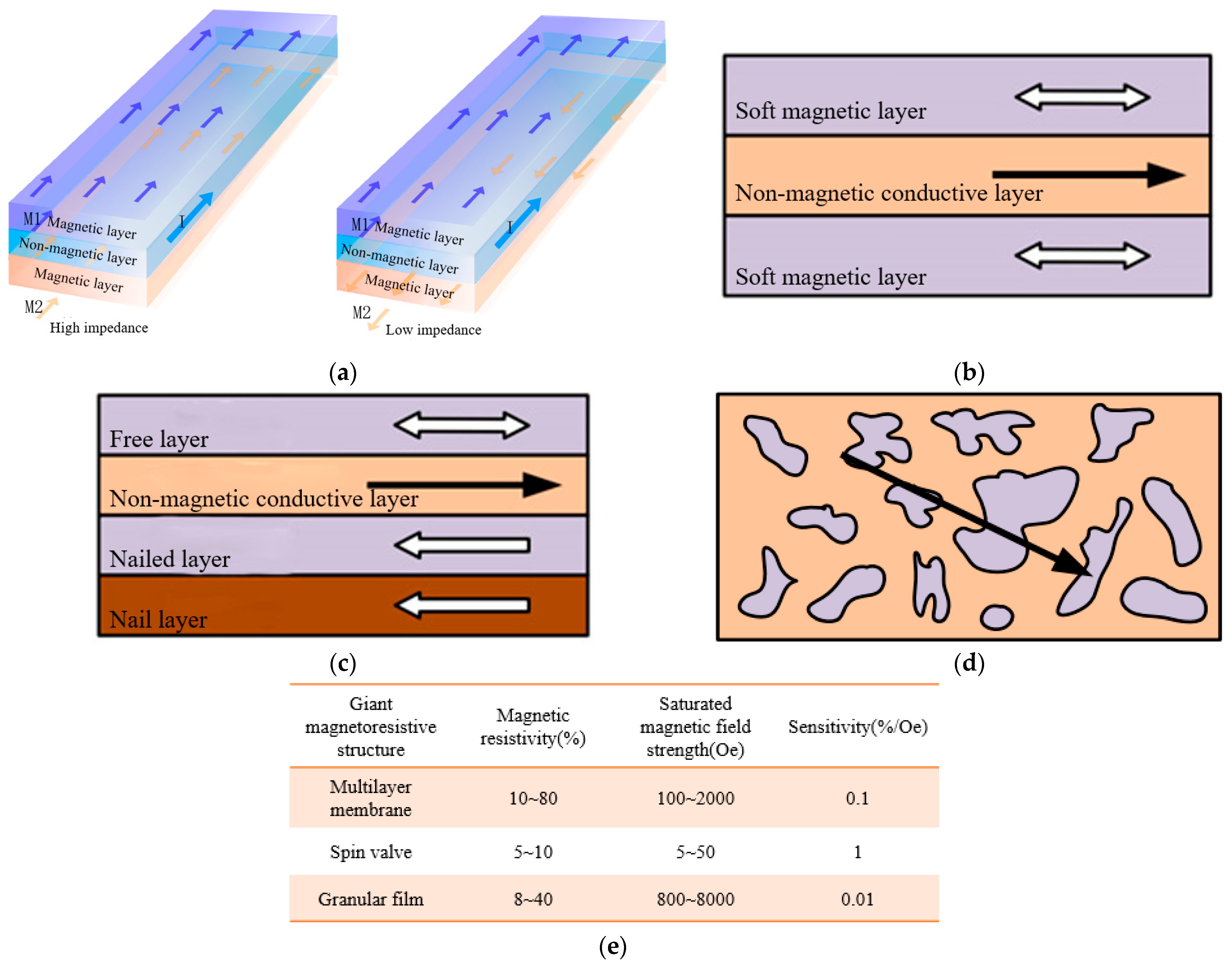
The GMR effect reflects a large change in the electrical resistance based on giant magneto-resistive (GMR) materials in the presence of a magnetic field, which was proposed by Peter Greenberger and Albert Fern in 1988 [44,45]. The GMR effect is a quantum effect that occurs in a multilayer film structure consisting of a ferromagnetic film and a non-ferromagnetic film, with the relative direction of the magnetic moments of the ferromagnetic layer and the non-ferromagnetic layer affecting the magnitude of the magneto-resistance [46]. The magneto-resistance of the ferromagnetic layers is smaller when the magnetic moments are in the same direction, while it would be larger in the opposite direction, as shown in Figure 11a. The GMR inductor can be divided into three types, including a multilayer membrane structure, spin valve structure and granular membrane structure, as shown in Figure 11b–e. The multilayer membrane structure is successfully applied in the fields of angle sensors and bioelectricity and the spin valve structure is successfully applied in the fields of magnetometers and weak magnetic detection [47,48].
GMR elements are used in the design of current sensors due to their high sensitivity and high resolution [49,50,51,52,53]. The GMR current sensors are also designed in a bridge structure, including a single bridge, half bridge and full bridge, as shown in Figure 12. Among them, the sensitivity of a single bridge is relatively low, so two single bridges are usually used to form a half-bridge structure to improve the sensitivity. The full-bridge structure has the largest gain, but its application is limited, with it being mainly applicable to the material system with a bipolar output. To apply the full-bridge structure to unipolar output material systems, an additional bias field must be introduced.
Figure 11. Principle of GMR effect and comparison of the performance of the three structures. (a) Schematic diagram of GMR effect. (b) Schematic diagram of multilayer membrane structure. (c) Schematic Structure of Spin Valve. (d) Schematic diagram of granular film structure. (e) Performance comparison of three structures of giant magneto-resistance [54].
Jlpea 14 00043 g011
In 2014, Yang et al. designed a GMR current sensor with magnetic shielding to address the susceptibility of GMR current sensors to external interfering magnetic fields [55,56,57]. In 2020, Mușuroi C et al. used planar coils to increase the magnetic field and designed GMR current sensors with a double-differential structure, which effectively improved its sensitivity and linearity for weak magnetic field detection [58].
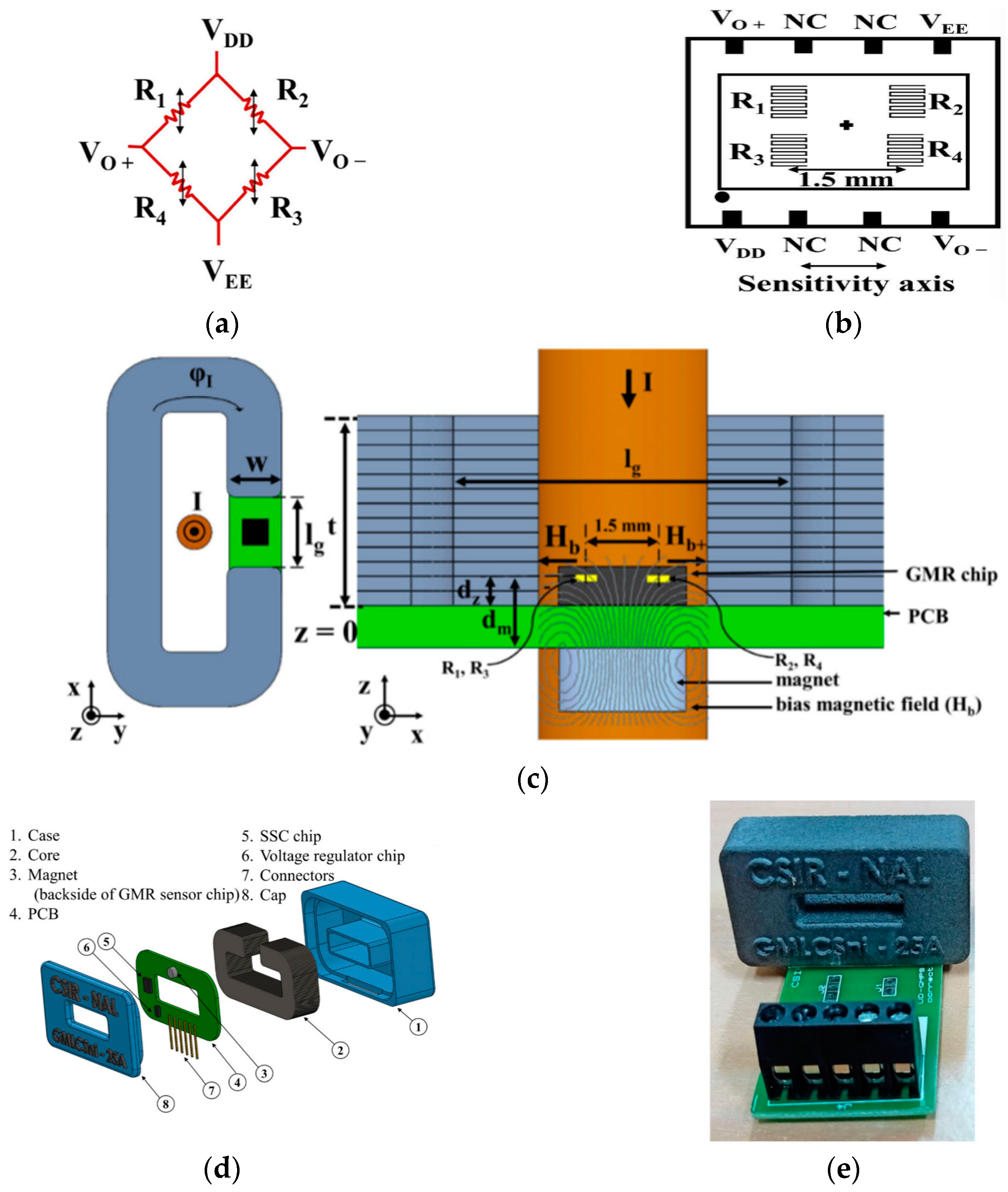
In 2023, Umesh P. Borole et al. designed and developed an open-loop GMR current sensor for industrial and aerospace applications, with sensitivities of a 0.165 mV/V/A order of magnitude, with a sensitivity versus temperature of −0.28%/°C and a bandwidth of 100 kHz. The sensor was designed based on a multilayer membrane structure with four GMR elements forming a Wheatstone bridge, as shown in Figure 13a,b. The schematic diagram of the current sensor is shown in Figure 13c, including a polymer ring, a GMR sensor and a bias magnet. Figure 13d,e show a 3D sectional view and a full-frame photograph of this current sensor. The sensor is tested and verified to meet the standards for industrial and aerospace applications [59]. Compared with traditional current sensors, GMR shows advantages in terms of sensitivity, cost, stability and size [54,60,61].

4.3. Tunneling Magneto-Resistance (TMR) Effect

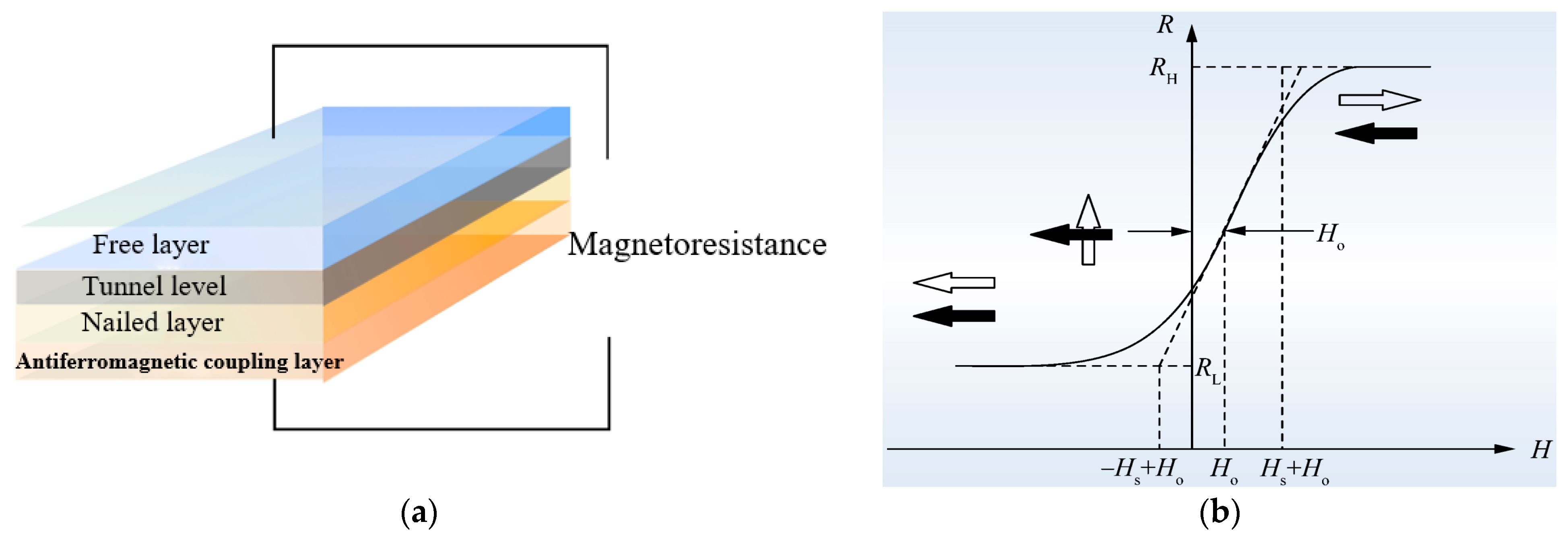
The TMR effect, also known as the magnetic tunnel junction (MTJ) effect, utilizes the magneto-resistive effect of magnetic multilayer materials to sense magnetic fields. The magnetic tunnel junction generally includes a sandwich structure of ferromagnetic layer/nonmagnetic insulating layer/ferromagnetic layer, in which the magnetization direction of the two ferromagnetic layers can be switched with an externally applied magnetic field, resulting in a change in the tunneling resistance, exhibiting the tunneling magneto-resistance effect [62,63,64,65,66]. Figure 14a shows its structure, in which the free and the pinned layers are ferromagnetic layers, while the tunneling layer is a non-magnetic insulating layer. There is also an antiferromagnetic coupling layer at the bottom of the pinned layer, which is used to fix the magnetic moment direction of the pinned layer. Ideally, the response curve of the TMR device is shown in Figure 14b, in which the white arrow is the magnetic moment direction of the free layer and the black arrow is the magnetic moment direction of the pinned layer. RL is the low-resistance state, RH is the high-resistance state, Ho is the offset field and H s + H o ~ H s + H o is the magnetic field region corresponding to the linear region.
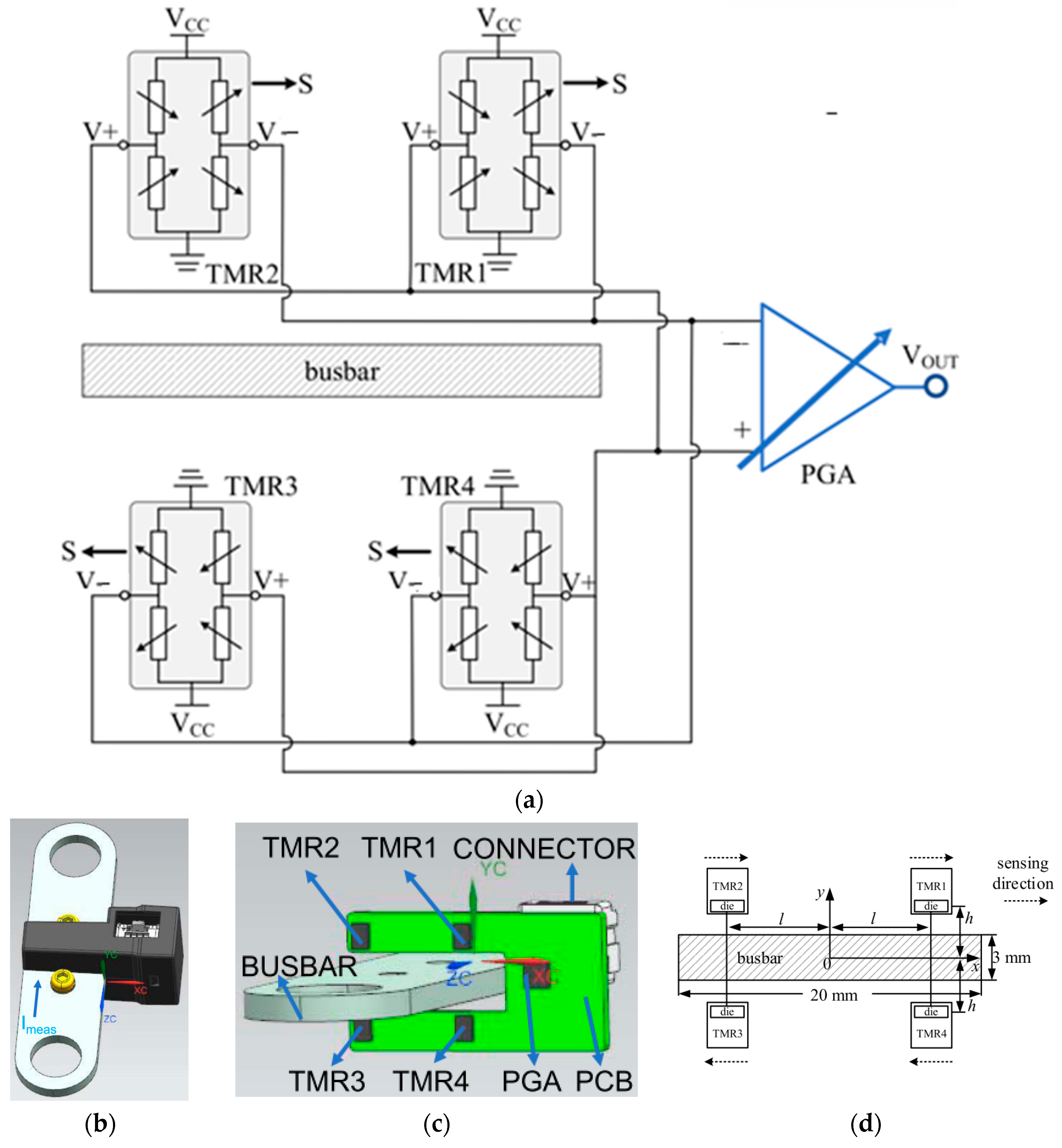
The TMR sensor shows a significantly improved performance in terms of sensitivity, the magnetic field measurement range and the operating temperature range [67]. J.Y. Chen et al. designed a current sensor based on a yoked MgO barrier MTJ device, which is less affected by low-frequency noise and can be applied in low-frequency magnetic field detection [68]. In 2020, Yu Hao et al. demonstrated that by increasing the number of TMR sensors and adjusting the initial angle of the array, the error factors, such as crosstalk, eccentricity, declination and geomagnetism, could be effectively suppressed and compensated for [69]. In 2021, X. P. Xu et al. proposed a busbar current sensor based on four TMR chips to suppress the error in detecting high-frequency currents. It is demonstrated that an error of less than 1.5% at frequencies up to 1 kHz can be fulfilled. The circuit structure is shown in Figure 15a, with S denoting the sensitivity direction of the TMR device. The current sensor consists of a programmable gain amplifier (PGA), TMR chip and busbar. Figure 15b–d show the internal and the external structures of the current sensor, with the relative position of the TMR chip showing in the figure. The simulation test proved that the current sensor has the advantages of flexible installation, a small size, high accuracy and good high-frequency characteristics [70]. In 2022, Zhihao Yu et al. designed a miniature non-contact high-voltage TMR current sensor, which meets the requirement of high-voltage current detection and improves the efficiency of the current detection [71].
The TMR sensor shows significant advantages over AMR and GMR sensors, including higher temperature stability and higher sensitivity, as well as a wider linear range with lower power consumption. In addition, the performance of the TMR current sensor is enhanced by the further optimization of the material properties, chip and circuit structures. However, some technical challenges still exist, such as the low-frequency noise or the signal-to-noise ratio (SNR) of the device. Its stability problem in 3D magnetic field detection needs to be further investigated [72].

4.4. Hall Effect

Edwin Herbert Hall discovered the Hall effect in 1879 when he was studying the mechanism of metal conductivity [73]. The Hall voltage is generated due to the bias of the current carrying charge by the Lorentz force of the external magnetic field, as shown in Figure 16. Its internally generated Hall voltage UH is:
U H = μ n σ d I B = 1 n q d I B = R H I d B
where μ n is the carrier mobility, σ is the conductivity and R H is the Hall coefficient. It shows that the Hall voltage U H is directly proportional to the perpendicular magnetic field B and the carrier mobility and inversely proportional to the conductivity and the carrier concentration. Since it is difficult to observe the Hall effect in conductors, most Hall elements are based on semiconductor materials, such as silicon and III-V compounds, which have high mobility and a relatively low conductivity [74]. Table 3 shows the key parameters of the Hall devices based on different materials, including the carrier mobility, carrier concentration and Hall coefficient of materials.
The Hall sensor is widely used in automotive, industrial production, defense and military industries. Since the Hall sensor is made of semiconductor material, it is greatly affected by the temperature, showing serious problems of temperature drift and low sensitivity. To solve this problem, Zhiyuan Xie and Yuxian Gu have designed an innovative method. By combining software and hardware technologies, the microcontroller, constant current source, digital temperature sensor, multiplier and other hardware circuits are controlled by the algorithms to conduct temperature compensation for the sensitivity of the open-loop Hall current sensor. In this way, the temperature drift of the sensor is significantly reduced compared to the pre-optimization period and the measurement accuracy of the Hall current sensor can be improved [75]. Zhiwei Qin and Wenke Lu et al. proposed a PSO-GA-LSSVM temperature compensation model to solve the problem of the Hall sensor output voltage drift with temperature [76]. The particle swarm optimization algorithm and the genetic algorithm are adopted to optimize the temperature compensation of the sensor output voltage. The results show that the Hall sensor with this design has a significant improvement in both the sensitivity and the temperature drift of the zero output.
Table 3. Summary of Hall Effect characterization parameters [77].
Semiconductor Material μ n   c m 2 V 1 s 1 n   c m 3 R H   c m 3 C 1
InSb80,0009 × 101670
InAs33,0005 × 1016125
GaAs85001.45 × 10154.3 × 103
Si15002.5 × 10152.5 × 103

5. Magnetic Current Sensors

The detection of the current with high accuracy is critical for the power system to satisfy the requirements of the safety and the power efficiency. In the power system, there are different waveforms and bandwidths. Many current sensors with different parameters have appeared on the market to meet different detection requirements [78,79,80].
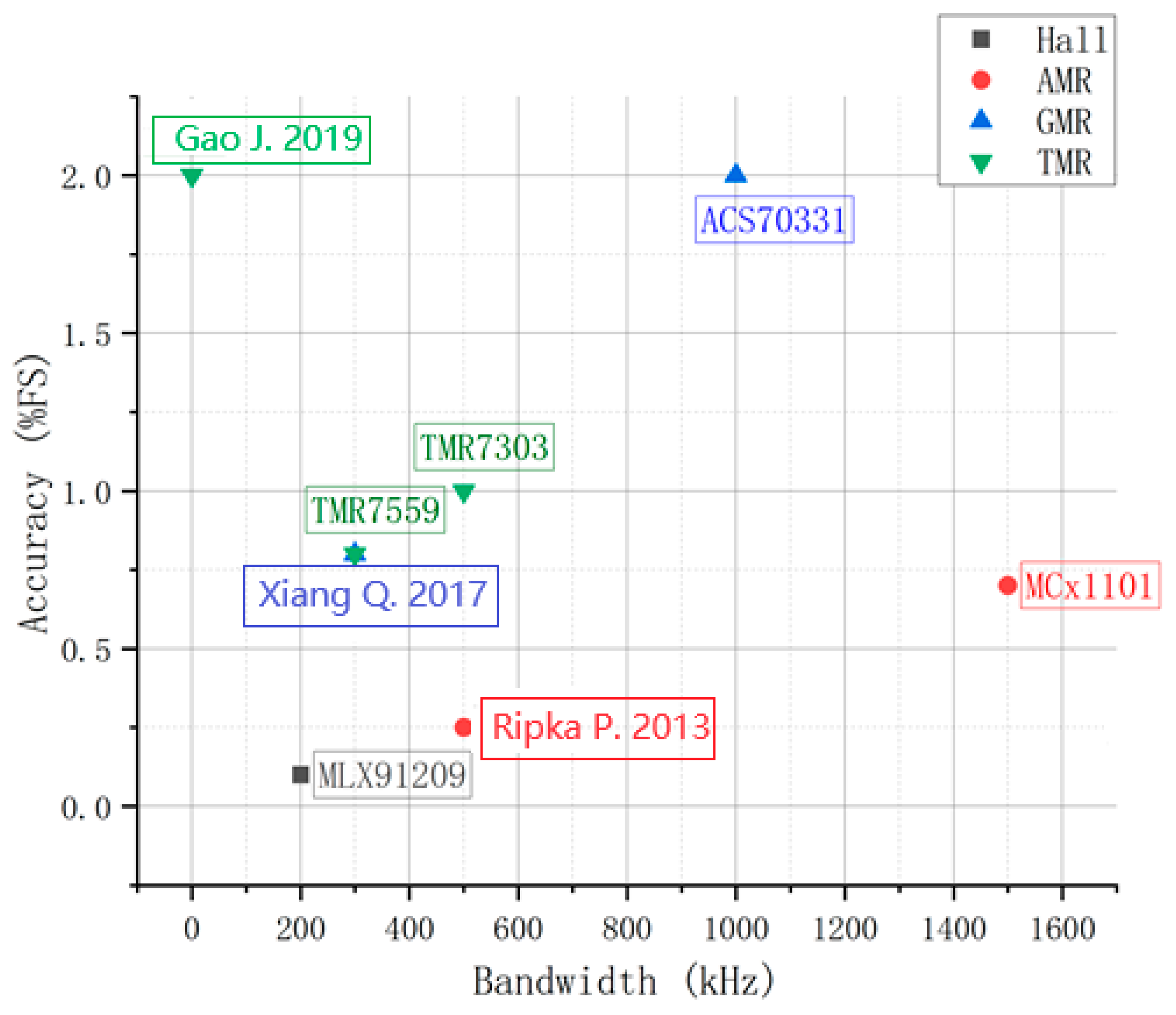
A comparison of various characteristics among Hall sensors and magneto-resistive sensors is shown in Table 4 [81,82,83]. For different application scenarios, Hall current sensors and magneto-resistive current sensors have their own advantages. Table 5 lists the various performance parameters of the available current sensors. Figure 17 shows the comparison of the performance of typical current sensors among them.

5.1. Amplifier Circuit of the Current Sensor

Generally, the output of the sensor is a differential voltage signal with a millivolts level, which can inevitably produce errors during the direct reading process. So, the output should be amplified, followed by arithmetic conditioning, filtering and other processing. The differential voltage contains a large common mode part, which requires the amplifier circuit to suppress the common mode signal and amplify the differential part [84]. An instrumentation amplifier has the characteristics of low DC drift, low noise, high open-loop gain and a large common-mode rejection ratio, which is commonly used as the interface circuit [85]. Figure 18 shows four typical types of the instrumentation amplifier.
Different structures of the instrumentation amplifiers can be applied according to different application scenarios and signal processing requirements. Table 6 lists the performance comparison.
Table 5. Comparison of recent published commercial current sensors.
SensorsPrinciple TypeStructure TypeBandwidthAccuracyOperating TemperatureApplication Scenario
MLX91209HallOpen-loop200 kHz0.1%−40~150 °CEV
MLX91221HallArray300 kHzN.A.−40~125 °CEV
TMR7303TMROpen-loop500 kHz1%−40~105 °CPhotovoltaic inverter
TMR7559TMRClosed-loop300 kHz0.8%−40~85 °CUPS
MCx1101AMRN.A.1.5 MHz0.7%−40~150 °CIndustrial power system
MCx2101AMRN.A.5 MHz3%−40~125 °CPhotovoltaic inverter
ACS70331GMRN.A.1 MHz2%−40~85 °CEV
ACS37002HallArray400 kHzN.A.−40~150 °CEV
CSLS SeriesHallOpen-loopN.A.N.A.−25~100 °CUPS
CSNA SeriesMRClosed-loopN.A.0.5%0~70 °CUPS
[86]Coil + HallArray1.8 MHzN.A.−40~85 °CN.A.
[87]AMRClosed-loop500 kHZ0.25%N.A.Medium-voltage power electronics
[88]GMROpen-loopN.A.0.8%−40~125 °CSmart grid
[89]TMROpen-loopDC2%−40~105 °CDC busbar system
[90]GMRClosed-loop300 kHZ0.8%N.A.N.A.
Table 6. Performance comparison of four instrumentation amplifiers [91].
Current-Mode Structure (Figure 18a)Current-Feedback Structure (Figure 18b)Capacitively Coupled Structure (Figure 18c)Triple Op-Amp Structure (Figure 18d)
Common-mode rejection ratioMiddleHighHighHigh
Equivalent Input NoiseMiddleLowLowLow
Input ImpedanceHighHighLowHigh
Output ImpedanceMiddleLowHighLow
P.G. Bahubalindruni et al. proposed a novel high-gain trans-impedance amplifier with a two-stage structure, as shown in Figure 19 [92]. Figure 19a shows the block diagram of the two-stage amplifier. The first stage consists of cascaded current mirrors (CCMs) and diode-connected loads. The stage can be used to realize current gain and to convert current into voltage, as shown in Figure 19b. In the second stage, the output voltages of the CCMs are connected with the differential positive feedback amplifier, as shown in Figure 19c. The output of the first stage should be connected to the gates of the input transistors (T1 and T2) of the second stage to minimize the load effect on the first stage amplifier. The designed trans-impedance amplifier shows a gain of about 149 dB and a power consumption of 0.45 mW.

5.2. Conditioning Circuit for Current Sensor

The conditioning circuit in the current sensor is typically used to process the sensor output signal to meet the requirements of a particular application. For example, the sensor output signal may contain noise or other interfering components. The conditioning circuit can be used to filter out these interfering components to improve the signal quality and reliability. Overall, the conditioning circuit plays a critical role in the high-end current sensor by optimizing the sensor output signal. The performance and the reliability of the entire measurement system can be improved with the conditioning circuit.
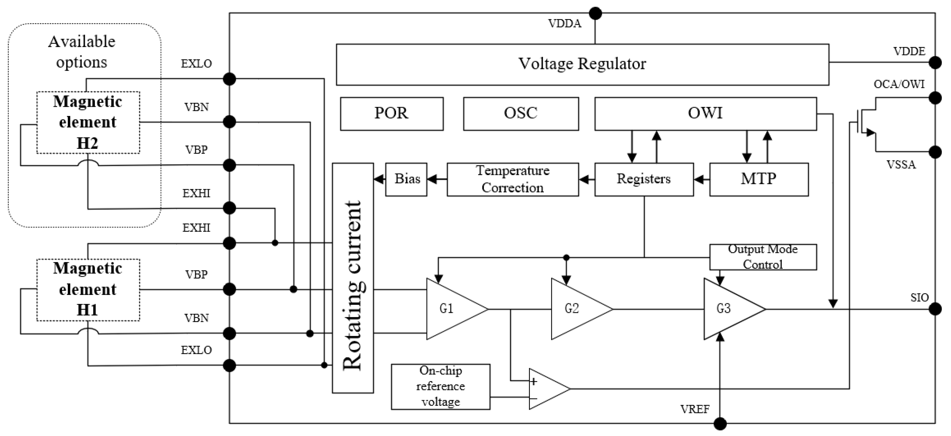
A signal conditioning circuit typically can be used to convert analog signals from sensors into digital signals used for data acquisition, process control, calculations, displays and other purposes. The architecture of the signal conditioning circuit designed in Jiangnan University is shown in Figure 20. In the design, two main signal paths are included in the signal conditioning architecture. The first is the main signal path, which is used to compensate the sensitivity of the output signal of the magnetic sensitive element, allowing the user to set the static voltage output under a zero magnetic field and finally output the conditioned signal. The second path is the temperature compensation signal path, which is used to measure the temperature of the current sensor in real time and adjust it according to the working status to reduce the drift of the conditioned signal in the main signal path. The designed integrated circuit is fabricated based on SMIC 0.18-μm CMOS technology.

5.3. Applications of Current Sensors

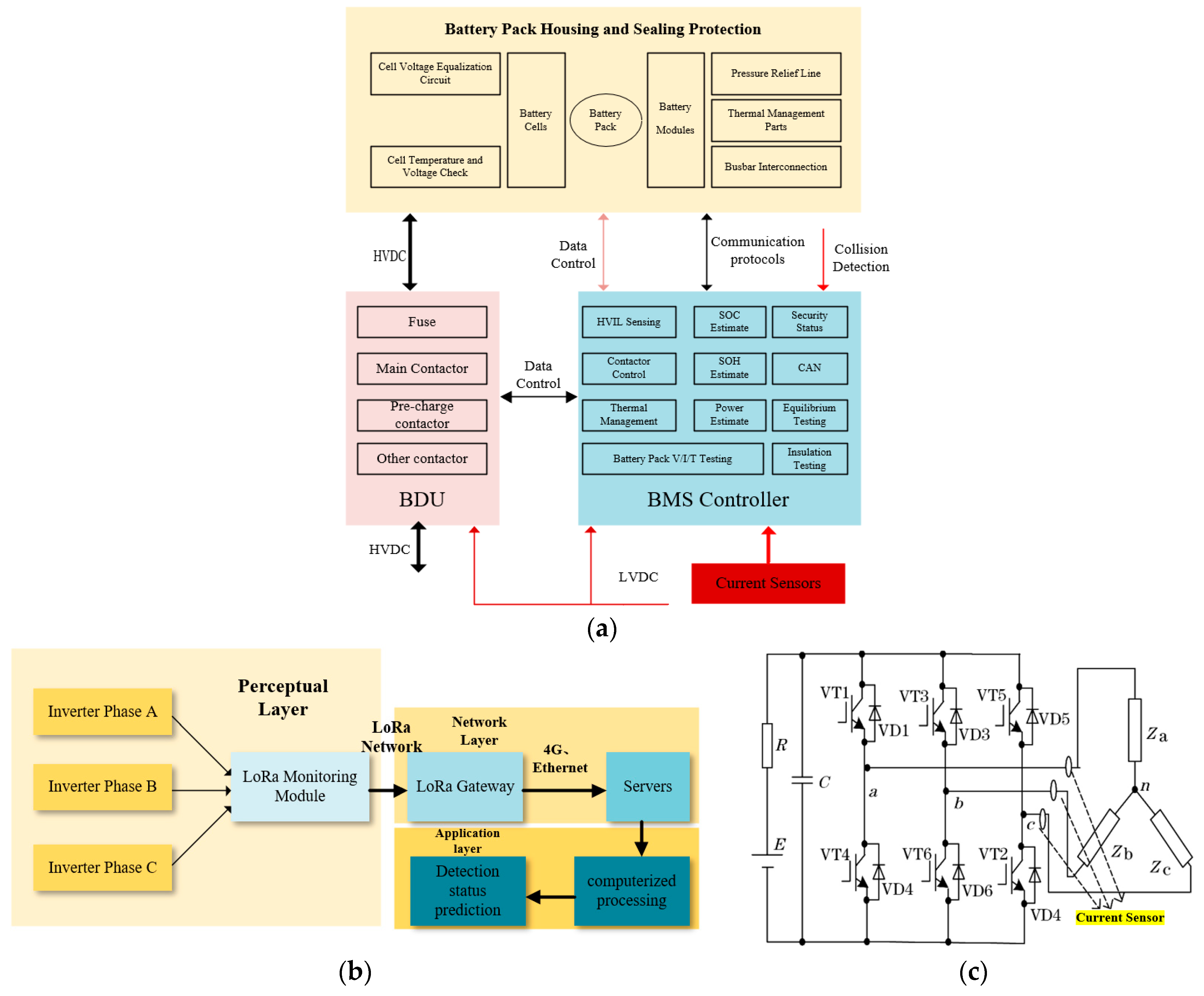
The current sensor plays an important role in electric vehicle charge management, power electronics and power systems [93,94]. A battery management system (BMS) is a specialized system for monitoring and controlling automotive batteries that is capable of tracking key parameters such as the battery voltage, current, load and temperature in real time [95]. In addition, the BMS is equipped with core functions such as safety monitoring, communication management, cell equalization and control management to ensure the safe and stable operation of the battery. The BMS also provides communication interfaces with application devices to facilitate data interactions with other systems and its architecture is shown in Figure 21a [96]. In the architecture, the current sensor helps to estimate the state of charge of the battery by measuring the current during the charge/discharge cycles. By accurately monitoring the current, the remaining capacity of the battery can be calculated by the BMS system. The information about its energy storage level can be obtained in this manner. By continuously monitoring the current, the BMS can optimize the charge and the discharge processes to improve the overall efficiency of the battery system. This includes regulating current levels to minimize energy loss and optimize battery pack performance [97]. The current sensors can also help to identify faults or anomalies in the battery system. In the battery system, sudden changes in the current could indicate problems such as short circuits, cell degradation or other malfunctions. On-time detection allows the BMS to take corrective action to prevent further damage [98].
Figure 21b shows the application of the current sensor in the photovoltaic system. The inverter is the core device of the photovoltaic panel, which directly reflects the operating status of the whole power-generation system. The online monitoring of the inverter is of great practical significance [99,100,101]. Gao Jing et al. designed a novel wireless monitoring system based on LoRa technology, showing low power consumption and a long communication distance [102]. This innovative design effectively prolongs the service life of the devices while improving the system effectiveness, as shown in Figure 21b. The data are initially obtained from the current sensors on the DC side of the inverter, as shown in Figure 21c. It is transmitted in real time to the computer software for processing. The data can be optimized using noise reduction filtering technology to accurately extract the operating status of the inverter and achieve online monitoring of the inverter operation, which ensures the stable operation and the efficient power generation of the whole system.
Figure 21. Application examples of the current sensor. (a) Schematic of BMS architecture [96]. The purple part denotes BDU. The blue part denotes BMS controller. The red ones denotes the current sensor. (b) Framework of PV inverter monitoring system. The blue ones denote LoRa module, including LoRa Monitoring Module, LoRa Gateway, and Servers. The left block denotes Perceptual Layer, while the right block Network Layer. (c) Locations of current sensors in the inverter [102].
Jlpea 14 00043 g021

6. Conclusions

The cutting-edge magneto-resistive current sensors, including AMR, GMR, TMR and Hall sensors, with high sensitivity and a wide temperature range, are introduced in this review. Based on the magneto-resistive effect, the magneto-resistive current sensor can be used to realize non-contact current measurements with high sensitivity, low power consumption and a strong anti-interference ability. Together with the continuous optimization of amplification and conditioning circuits, the magneto-resistive current sensor shows wide applications in modern power systems and EV systems.
With the continuous advancement of technology, future current sensors should show higher precision and sensitivity to satisfy the growing demand for precise measurements. This requires improvements in the adopted materials and signal processing technologies in the sensor. The highly sensitive nanomaterials or advanced quantum techniques can be combined with the current sensor to obtain advanced results.
In terms of applications, intelligence and adaptability should be achieved, for example, by optimizing current detection parameters through machine learning algorithms and automatically calibrating and compensating for environmental factors. The size and the power consumption should be reduced continuously. The integration of the current sensor into the microchip helps to move towards continuous development in a more miniaturized, energy-efficient and environmentally friendly direction.

Author Contributions

Methodology, Z.Y.; writing—original draft, Z.Y.; writing—review and editing, Y.J.; supervision, Y.J. All authors have read and agreed to the published version of the manuscript.

Funding

This work was supported in part by the Leading Technology Pre-Research Project (No. XD23008, Wuxi Industrial Innovation Research Institute and Jiangsu JITRI IC Application Technology Innovation Center), the National Natural Science Foundation of China under Grant No. 61774078 and the Natural Science Foundation of the Jiangsu Province (BK20210453).

Data Availability Statement

The data that support the findings of this study are available from the corresponding author upon reasonable request.

Conflicts of Interest

The authors declare no conflicts of interest.

References

  1. Brown, P.; Whiteside, B.J.; Beek, T.J.; Fox, P.; Horbury, T.S.; Oddy, T.M.; Archer, M.O.; Eastwood, J.P.; Sanz-Hernández, D.; Sample, J.G.; et al. Space magnetometer based on an anisotropic magnetoresistive hybrid sensor. Rev. Sci. Instrum. 2014, 85, 125117. [Google Scholar] [CrossRef] [PubMed]
  2. Sun, H.; Huang, S.; Peng, L. High-Current Sensing Technology for Transparent Power Grids: A Review. IEEE Open J. Ind. Electron. Soc. 2024, 5, 326–358. [Google Scholar] [CrossRef]
  3. Zhang, S. PCB Design of Rogowski Coil with Strong Anti-Electromagnetic Interference. In Proceedings of the 3rd Asia-Pacific Conference on Image Processing, Electronics and Computers, Dalian, China, 14–16 April 2022; pp. 478–485. [Google Scholar]
  4. Huang, Q.; Zhang, C.; Liu, Q.; Ning, Y.; Cao, Y. New type of fiber optic sensor network for smart grid interface of transmission system. In Proceedings of the IEEE PES General Meeting, Minneapolis, MN, USA, 25–29 July 2010; pp. 1–5. [Google Scholar]
  5. Lee, B. Review of the present status of optical fiber sensors. Opt. Fiber Technol. 2003, 9, 57–79. [Google Scholar] [CrossRef]
  6. Thompson, S.M. The discovery, development and future of GMR: The Nobel Prize 2007. J. Phys. D Appl. Phys. 2008, 41, 093001. [Google Scholar] [CrossRef]
  7. Xie, F.; Weiss, R.; Weigel, R. Improved mathematical operations based calibration method for giant magnetoresistive current sensor applying B-Spline modeling. Sens. Actuators A Phys. 2017, 254, 109–115. [Google Scholar] [CrossRef]
  8. McGuire, T.; Potter, R. Anisotropic magnetoresistance in ferromagnetic 3d alloys. IEEE Trans. Magn. 1975, 11, 1018–1038. [Google Scholar] [CrossRef]
  9. Ritzinger, P.; Výborný, K. Anisotropic magnetoresistance: Materials, models and applications. R. Soc. Open Sci. 2023, 10, 230564. [Google Scholar] [CrossRef]
  10. Yang, S.; Zhang, J. Current Progress of Magnetoresistance Sensors. Chemosensors 2021, 9, 211. [Google Scholar] [CrossRef]
  11. Ramsden, E. Hall-Effect Sensors: Theory and Applications; Newnes: Amsterdam, The Netherlands, 2006. [Google Scholar]
  12. Liu, X.; Lam, K.H.; Zhu, K.; Zheng, C.; Li, X.; Du, Y.; Liu, C.; Pong, P.W.T. Overview of Spintronic Sensors with Internet of Things for Smart Living. IEEE Trans. Magn. 2019, 55, 1–22. [Google Scholar] [CrossRef]
  13. Palneedi, H.; Annapureddy, V.; Priya, S.; Ryu, J. Status and Perspectives of Multiferroic Magnetoelectric Composite Materials and Applications. Actuators 2016, 5, 9. [Google Scholar] [CrossRef]
  14. Stoney, R.; Geraghty, D.; Donnell, G.E.O. Characterization of Differentially Measured Strain Using Passive Wireless Surface Acoustic Wave (SAW) Strain Sensors. IEEE Sens. J. 2014, 14, 722–728. [Google Scholar] [CrossRef]
  15. Thormählen, L.; Seidler, D.; Schell, V.; Munnik, F.; McCord, J.; Meyners, D. Sputter Deposited Magnetostrictive Layers for SAW Magnetic Field Sensors. Sensors 2021, 21, 8386. [Google Scholar] [CrossRef] [PubMed]
  16. Du, Y.; Liu, Q.; Huang, A.Q. A monolithic CMOS synchronous Buck converter with a fast and low-cost current sensing scheme. In Proceedings of the 2012 IEEE Energy Conversion Congress and Exposition (ECCE), Raleigh, NC, USA, 15–20 September 2012; pp. 1849–1856. [Google Scholar] [CrossRef]
  17. Zhang, Q.; Liu, J.; Yang, Y. A new complementary symmetrical structure of using dual magnetic cores for open loop Hall-Effect current sensors. In Proceedings of the PCIM Europe 2015, International Exhibition and Conference for Power Electronics, Intelligent Motion, Renewable Energy and Energy Management, Nuremberg, Germany, 19–20 May 2015; pp. 1–8. [Google Scholar]
  18. Zhou, L.; Chen, Q.; Li, H.; Yang, S.; Pang, D.; Deng, H. A Non-Contact Micro-Ampere DC Current Digital Sensor Based on the Open-Loop Structure. IEEE Sens. J. 2021, 21, 5923–5931. [Google Scholar] [CrossRef]
  19. Tan, C.; Wu, C.; Gong, X.; Li, X.; Fu, R.; Yue, Z. New Magnetic Circuit Structure of Hall Current Sensor for Reducing Conductor Position Error. Sens. Mater. 2020, 32, 2891. [Google Scholar] [CrossRef]
  20. Carretero, C.; Lope, I.; Acero, J. Magnetizable Concrete Flux Concentrators for Wireless Inductive Power Transfer Applications. IEEE J. Emerg. Sel. Top. Power Electron. 2020, 8, 2696–2706. [Google Scholar] [CrossRef]
  21. Morón, C.; Cabrera, C.; Morón, A.; García, A.; González, M. Magnetic Sensors Based on Amorphous Ferromagnetic Materials: A Review. Sensors 2015, 15, 28340–28366. [Google Scholar] [CrossRef] [PubMed]
  22. Khan, M.A.; Sun, J.; Li, B.; Przybysz, A.; Kosel, J. Magnetic sensors—A review and recent technologies. Eng. Res. Express 2021, 3, 022005. [Google Scholar] [CrossRef]
  23. Fish, G.E. Soft magnetic materials. Proc. IEEE 1990, 78, 947–972. [Google Scholar] [CrossRef]
  24. Li, Z.; Dixon, S. A Closed-Loop Operation to Improve GMR Sensor Accuracy. IEEE Sens. J. 2016, 16, 6003–6007. [Google Scholar] [CrossRef]
  25. Parsa Sirat, A.; Parkhideh, B. Current Sensor Integration Issues with Wide-Bandgap Power Converters. Sensors 2023, 23, 6481. [Google Scholar] [CrossRef]
  26. Storms, W.; Shockley, J.; Raquet, J. Magnetic field navigation in an indoor environment. In Proceedings of the 2010 Ubiquitous Positioning Indoor Navigation and Location Based Service, Kirkkonummi, Finland, 14–15 October 2010; pp. 1–10. [Google Scholar] [CrossRef]
  27. Hu, C.; Li, M.; Song, S.; Yang, W.; Zhang, R.; Meng, M.Q.H. A Cubic 3-Axis Magnetic Sensor Array for Wirelessly Tracking Magnet Position and Orientation. IEEE Sens. J. 2010, 10, 903–913. [Google Scholar] [CrossRef]
  28. Yang, A.; Liu, M.; Wang, Y.; Wu, Y.; Zhu, L.; Fan, Y. Research on High-Frequency Current Sensor and Measurement Method Based on Magnetic Sensor Array. In Proceedings of the 2023 12th International Conference of Information and Communication Technology (ICTech), Wuhan, China, 14–16 April 2023; pp. 556–562. [Google Scholar]
  29. Leroy, P.; Coillot, C.; Mosser, V.; Roux, A.; Chanteur, G. Use of Magnetic Concentrators to Highly Improve the Sensitivity of Hall Effect Sensors. Sens. Lett. 2007, 5, 162–166. [Google Scholar] [CrossRef]
  30. Navau, C.; Mach-Batlle, R.; Parra, A.; Prat-Camps, J.; Laut, S.; Del-Valle, N.; Sanchez, A. Enhancing the sensitivity of magnetic sensors by 3D metamaterial shells. Sci. Rep. 2017, 7, 44762. [Google Scholar] [CrossRef]
  31. Gobbi, M.; Orgiu, E. The Rise of the Organic Magnetoresistance: Materials and Challenges. J. Mater. Chem. C 2017, 5, 5572–5580. [Google Scholar] [CrossRef]
  32. Zheng, X.Q.; Wu, H.; Chen, J.; Zhang, B.; Li, Y.Q.; Hu, F.X.; Sun, J.R.; Huang, Q.Z.; Shen, B.G. The physical mechanism of magnetic field controlled magnetocaloric effect and magnetoresistance in bulk PrGa compound. Sci. Rep. 2015, 5, 14970. [Google Scholar] [CrossRef] [PubMed]
  33. Ma, J.; Hu, J.; Li, Z.; Nan, C.W. Recent Progress in Multiferroic Magnetoelectric Composites: From Bulk to Thin Films (Adv. Mater. 9/2011). Adv. Mater. 2011, 23, 1061. [Google Scholar] [CrossRef]
  34. Tan, J.; Zhang, X.; Chen, L. Accurate measurement technology for magnetic field based on AMR sensor SET/RESET function. China Meas. Test 2018, 44, 88–92. [Google Scholar]
  35. Pei, Y.; Yu, N.; Liu, Q.; Liu, J. Theory and Application of Anisotropic Magnetoresistive Sensor. Intstrument Tech. Sens. 2004, 8, 26–27. [Google Scholar]
  36. Brown, P.; Beek, T.; Carr, C.; O’Brien, H.; Cupido, E.; Oddy, T.; Horbury, T.S. Magnetoresistive magnetometer for space science applications. Meas. Sci. Technol. 2012, 23, 025902. [Google Scholar] [CrossRef]
  37. Li, T.; Zhang, L.; Hong, X. Anisotropic magnetoresistance and planar Hall effect in correlated and topological materials. J. Vac. Sci. Technol. A 2022, 40, 010807. [Google Scholar] [CrossRef]
  38. Zhang, X.; Yang, G.; Lai, Z.; Zhao, D. High-Precision Measuring Technique of AMR Magnetic Sensor. J. Test Meas. Technol. 2015, 29, 73–77. [Google Scholar]
  39. Quynh, L.K.; Tu, B.D.; Dang, D.X.; Viet, D.Q.; Hien, L.T.; Huong Giang, D.T.; Duc, N.H. Detection of magnetic nanoparticles using simple AMR sensors in Wheatstone bridge. J. Sci. Adv. Mater. Devices 2016, 1, 98–102. [Google Scholar] [CrossRef]
  40. Mlejnek, P.; Vopálenský, M.; Ripka, P. AMR current measurement device. Sens. Actuators A Phys. 2008, 141, 649–653. [Google Scholar] [CrossRef]
  41. Yin, D.; Zhang, X.; Kwan, K.H.; Wang, G. Research of Current Measurement System Based on Two-axis Anisotropic Magnetoresistive Sensor. J. Power Supply 2018, 16, 178–184. [Google Scholar] [CrossRef]
  42. Belyakov, P.; Amelichev, V.; Kostyuk, D.; Kazakov, Y.; Orlov, E.; Zhukov, D.; Vasilyev, D. Current Sensor Based on Anisotropic Magnetoresistive Effect. IEEE Trans. Magn. 2021, 57, 1–4. [Google Scholar] [CrossRef]
  43. Ripka, P.; Janosek, M. Advances in Magnetic Field Sensors. IEEE Sens. J. 2010, 10, 1108–1116. [Google Scholar] [CrossRef]
  44. Baibich, M.N.; Broto, J.M.; Fert, A.; Van Dau, F.N.; Petroff, F.; Etienne, P.; Creuzet, G.; Friederich, A.; Chazelas, J. Giant magnetoresistance of (001)Fe/(001)Cr magnetic superlattices. Phys. Rev. Lett. 1988, 61, 2472–2475. [Google Scholar] [CrossRef]
  45. Grünberg, P.E.; Schreiber, R.; Pang, Y.; Brodsky, M.B.; Sowers, H. Layered magnetic structures: Evidence for antiferromagnetic coupling of Fe layers across Cr interlayers. Phys. Rev. Lett. 1986, 57, 2442–2445. [Google Scholar] [CrossRef]
  46. Noh, E.S.; Lee, H.M.; Ulloa, S. A theoretical study of the effect of electronic structures of ferromagnets on giant magnetoresistance. J. Korean Phys. Soc. 2006, 48, 451–459. [Google Scholar]
  47. Becker, C.; Karnaushenko, D.; Kang, T.; Karnaushenko, D.D.; Faghih, M.; Mirhajivarzaneh, A.; Schmidt, O.G. Self-assembly of highly sensitive 3D magnetic field vector angular encoders. Sci. Adv. 2019, 5, eaay7459. [Google Scholar] [CrossRef]
  48. Adem, S.; Jain, S.; Sveiven, M.; Zhou, X.; O’Donoghue, A.J.; Hall, D.A. Giant magnetoresistive biosensors for real-time quantitative detection of protease activity. Sci. Rep. 2020, 10, 7941. [Google Scholar] [CrossRef]
  49. Daughton, J.M.; Chen, Y.J. GMR materials for low-field applications. IEEE Trans. Magn. 1993, 29, 2705–2710. [Google Scholar] [CrossRef]
  50. Bonavolonta, C.; Valentino, M.; Penta, F.; Granata, C.; Ruggiero, B.; Silvestrini, P.; Vettoliere, A. Detection of Magnetomechanical Effect in Structural Steel Using GMR 2nd Order Gradiometer Based Sensors. Sensors 2019, 19, 4147. [Google Scholar] [CrossRef] [PubMed]
  51. Li, Q.; Wolfs, P. A review of the single phase photovoltaic module integrated converter topologies with three different dc link configurations. IEEE Trans. Power Electron. 2008, 23, 1320–1333. [Google Scholar] [CrossRef]
  52. Qian, Z.H.; Wang, D.X.; Daughton, J.M.; Tondra, M.; Nordman, C.; Popple, A. Linear spin-valve bridge sensing devices. IEEE Trans. Magn. 2004, 40, 2643–2645. [Google Scholar] [CrossRef]
  53. Takeo, A.; Taguchi, T.; Sakai, Y.; Tanaka, Y. Characterization of GMR nonlinear response and the impact on BER in perpendicular magnetic recording. IEEE Trans. Magn. 2004, 40, 2582–2584. [Google Scholar] [CrossRef]
  54. Reig, C.; Cubells-Beltrán, M.-D.; Ramírez Muñoz, D. Magnetic Field Sensors Based on Giant Magnetoresistance (GMR) Technology: Applications in Electrical Current Sensing. Sensors 2009, 9, 7919–7942. [Google Scholar] [CrossRef]
  55. Yang, X.; Xie, C.; Wang, Y.; Wang, Y.; Yang, W.; Dong, G. Optimization Design of a Giant Magneto Resistive Effect Based Current Sensor with a Magnetic Shielding. IEEE Trans. Appl. Supercond. 2014, 24, 1–4. [Google Scholar] [CrossRef]
  56. Yang, X.; Liu, H.; Wang, Y.; Wang, Y.; Dong, G.; Zhao, Z. A Giant Magneto Resistive (GMR) Effect Based Current Sensor with a Toroidal Magnetic Core as Flux Concentrator and Closed-Loop Configuration. IEEE Trans. Appl. Supercond. 2014, 24, 1–5. [Google Scholar] [CrossRef]
  57. Wang, X.; Ren, S.; Yang, H.; Wang, B. FEM Analysis of Magnetic Shielding Effectiveness. Acta Metrol. Sin. 2006, 27, 376–379. [Google Scholar]
  58. Musuroi, C.; Oproiu, M.; Volmer, M.; Neamtu, J.; Avram, M.; Helerea, E. Low Field Optimization of a Non-Contacting High-Sensitivity GMR-Based DC/AC Current Sensor. Sensors 2021, 21, 2564. [Google Scholar] [CrossRef]
  59. Borole, U.P.; Barshilia, H.C.; Ananda, C.M.; Chowdhury, P. Design, Development, and Performance Evaluation of GMR-Based Current Sensor for Industrial and Aerospace Applications. IEEE Sens. J. 2023, 23, 12687–12694. [Google Scholar] [CrossRef]
  60. Musuroi, C.; Oproiu, M.; Volmer, M.; Firastrau, I. High Sensitivity Differential Giant Magnetoresistance (GMR) Based Sensor for Non-Contacting DC/AC Current Measurement. Sensors 2020, 20, 323. [Google Scholar] [CrossRef] [PubMed]
  61. Ouyang, Y.; Wang, Z.; Zhao, G.; Hu, J.; Ji, S.; He, P.; Wang, S.X. Current sensors based on GMR effect for smart grid applications. Sens. Actuators A-Phys. 2019, 294, 8–16. [Google Scholar] [CrossRef]
  62. Wang, H.; Guo, H.; Wang, Y.; Wang, Z.; Guo, Y. Research of current sensor based on TMR device. Electr. Meas. Instrum. 2018, 55, 103–107. [Google Scholar]
  63. Jilili, J.; Sadeh, B. Principle and Application of Tunneling Magnetoresistance Effect. Mater. Rep. 2009, 23, 338–340+349. [Google Scholar]
  64. Ouyang, Y.; He, J.; Hu, J.; Zhao, G.; Wang, Z.; Wang, S.X. Contactless Current Sensors Based on Magnetic Tunnel Junction for Smart Grid Applications. IEEE Trans. Magn. 2015, 51, 1–4. [Google Scholar] [CrossRef]
  65. Li, Y.-B.; Wei, F.-L.; Zheng, Y. Tunnelling magnetoresistance effects of magnetic tunnel junctions. Physics 2009, 38, 420–426. [Google Scholar]
  66. Zhang, P.; Li, Q.; Zhang, W.; Liu, C. Study on Design of Tunneling Magnetoresistance Current Sensor. Instrum. Tech. Sens. 2019, 12, 23–26. [Google Scholar]
  67. Lei, M.; Peng, T.; Yu, J.; Zhou, F.; Liu, J.; Li, L. Optimal design and implementation of tunnelling magnetoresistance based small current sensor with temperature compensation. Energy Rep. 2022, 8, 137–146. [Google Scholar] [CrossRef]
  68. Chen, J.Y.; Carroll, N.; Feng, J.F.; Coey, J.M.D. Yoke-shaped MgO-barrier magnetic tunnel junction sensors. Appl. Phys. Lett. 2012, 101, 262402. [Google Scholar] [CrossRef]
  69. Yu, H.; Chang, W.; Du, F.; Wang, G. Research on Anti-Interference Principle of Current Sensor Based on Circular Array of TMR. Electr. Power Inf. Commun. Technol. 2020, 18, 7–14. [Google Scholar] [CrossRef]
  70. Xu, X.P.; Wang, S.; Liu, T.Z.; Zhu, M.; Wang, J.G. TMR Busbar Current Sensor with Good Frequency Characteristics. IEEE Trans. Instrum. Meas. 2021, 70, 1–9. [Google Scholar] [CrossRef]
  71. Yu, Z.; Wang, J.; Chen, W.; Ye, K. Micro Contactless High Voltage Current Sensor Based on TMR. Power Electron. 2022, 56, 51. [Google Scholar]
  72. Pavel, R. Magnetic Sensors and Magnetometers, 2nd ed.; Artech: Dallas, TX, USA, 2021; p. 1. [Google Scholar]
  73. Beer, A.C.; Morgan, K.Z.; Peters, R.W.; Dittman, R.H.; Phillips, N.E.; Eckert, E.R.G.; Loeb, A.L.; Trump, J.G.; Hujer, K.; Smith, H.M.H. The Encyclopedia of Physics; Besançon, R.M., Ed.; Springer: Boston, MA, USA, 1990; pp. 538–573. [Google Scholar]
  74. Ellmer, K. Hall Effect and Conductivity Measurements in Semiconductor Crystals and Thin Films. In Characterization of Materials; John Wiley & Sons Inc.: Hoboken, NJ, USA, 2012; pp. 1–16. [Google Scholar]
  75. Xie, Z.; Gu, Y. Research on Temperature Compensation of Open-loop Hall Current Sensor Based on STM32. Optoelectron. Technol. 2020, 40, 63–69. [Google Scholar] [CrossRef]
  76. Qin, Z.; Lu, W.; Zuo, F.; Feng, Y. Temperature Compensation of Hall Effect Displacement Sensor. Chin. J. Sens. Actuators 2019, 32, 1040–1044. [Google Scholar]
  77. Crescentini, M.; Syeda, S.F.; Gibiino, G.P. Hall-Effect Current Sensors: Principles of Operation and Implementation Techniques. IEEE Sens. J. 2022, 22, 10137–10151. [Google Scholar] [CrossRef]
  78. Velasco-Quesada, G.; Román-Lumbreras, M.; Conesa-Roca, A.; Jeréz, F. Design of a Low-Consumption Fluxgate Transducer for High-Current Measurement Applications. IEEE Sens. J. 2011, 11, 280–287. [Google Scholar] [CrossRef]
  79. Ripka, P.; Draxler, K.; Styblikova, R. Measurement of DC Currents in the Power Grid by Current Transformer. IEEE Trans. Magn. 2013, 49, 73–76. [Google Scholar] [CrossRef]
  80. Itzke, A.; Weiss, R.; Weigel, R. Influence of the Conductor Position on a Circular Array of Hall Sensors for Current Measurement. IEEE Trans. Ind. Electron. 2019, 66, 580–585. [Google Scholar] [CrossRef]
  81. Gao, J.; Wang, J.; Zhang, L.; Yu, Q.; Huang, Y.; Shen, Y. Magnetic Signature Analysis for Smart Security System Based on TMR Magnetic Sensor Array. IEEE Sens. J. 2019, 19, 3149–3155. [Google Scholar] [CrossRef]
  82. Xiang, Q.; Yue, C.; Hu, C.; Zhu, K.; Gong, H.; Wang, H. Hall effect element array based current measurement system. Electr. Meas. Instrum. 2017, 54, 105–110. [Google Scholar]
  83. Zhang, H.; Liu, X.; Wang, X.; Huo, M. Principles and applications of magneto-resistance effect. J. Harbin Inst. Technol. 2008, 40, 362–366. [Google Scholar]
  84. He, X. Design of a high-performance differential amplifier for collecting electrocardiogram signals. In Proceedings of the 2023 IEEE 6th International Conference on Information Systems and Computer Aided Education (ICISCAE), Dalian, China, 23–25 September 2023; pp. 805–810. [Google Scholar]
  85. Zhang, S.; Zhou, X.; Gao, C.; Li, Q. A 130-dB CMRR Instrumentation Amplifier With Common-Mode Replication. IEEE J. Solid-State Circuits 2022, 57, 278–289. [Google Scholar] [CrossRef]
  86. Jouyaeian, A.; Fan, Q.; Motz, M.; Ausserlechner, U.; Makinwa, K.A.A. 5.6 A 25 A Hybrid Magnetic Current Sensor with 64 mA Resolution, 1.8 MHz Bandwidth, and a Gain Drift Compensation Scheme. In Proceedings of the 2021 IEEE International Solid-State Circuits Conference (ISSCC), San Francisco, CA, USA, 13–22 February 2021; pp. 82–84. [Google Scholar]
  87. Ravi, L.; Liu, J.; Schmalz, S.; Schroedermeier, A.; Burgos, R.; Dong, D. A Compact Anisotropic Magnetoresistance Based Contactless Current Sensor for Medium Voltage Power Electronics Applications. In Proceedings of the 2023 IEEE Applied Power Electronics Conference and Exposition (APEC), Orlando, FL, USA, 19–23 March 2023; pp. 1670–1675. [Google Scholar]
  88. Xu, A.; Wang, Z.; Li, P.; Li, L.; Hao, C. Research and Application of Micro Current Sensor Based on Giant Magnetoresistance Effect. South. Power Syst. Technol. 2020, 14, 33–40. [Google Scholar]
  89. Xu, X.P.; Liu, T.Z.; Zhu, M.; Wang, J.G. New Small-Volume High-Precision TMR Busbar DC Current Sensor. IEEE Trans. Magn. 2020, 56, 1–5. [Google Scholar] [CrossRef]
  90. Yang, X.; Wen, J.; Xie, C.; Gao, Z.; Li, Y.; Xi, L. Design and Experimental Study of a Current Sensor Based on Multilayer GMR Material. Chin. J. Sens. Actuators 2020, 33, 12–16. [Google Scholar]
  91. Lin, T.N.; Wang, B.; Bermak, A. Review and Analysis of Instrumentation Amplifier for IoT Applications. In Proceedings of the 2018 IEEE 61st International Midwest Symposium on Circuits and Systems (MWSCAS), Windsor, ON, Canada, 5–8 August 2018; pp. 258–261. [Google Scholar]
  92. Bahubalindruni, P.G.; Martins, J.; Santa, A.; Tavares, V.; Martins, R.; Fortunato, E.; Barquinha, P. High-Gain Transimpedance Amplifier for Flexible Radiation Dosimetry Using InGaZnO TFTs. IEEE J. Electron Devices Soc. 2018, 6, 760–765. [Google Scholar] [CrossRef]
  93. Habib, S.; Khan, M.M.; Abbas, F.; Ali, A.; Faiz, M.T.; Ehsan, F.; Tang, H. Contemporary trends in power electronics converters for charging solutions of electric vehicles. CSEE J. Power Energy Syst. 2020, 6, 911–929. [Google Scholar] [CrossRef]
  94. Safayatullah, M.; Elrais, M.T.; Ghosh, S.; Rezaii, R.; Batarseh, I. A Comprehensive Review of Power Converter Topologies and Control Methods for Electric Vehicle Fast Charging Applications. IEEE Access 2022, 10, 40753–40793. [Google Scholar] [CrossRef]
  95. Nizam, M.; Maghfiroh, H.; Rosadi, R.A.; Kusumaputri, K.D.U. Battery management system design (BMS) for lithium ion batteries. In AIP Conference Proceedings; AIP Publishing: Melville, NY, USA, 2020; Volume 2217. [Google Scholar] [CrossRef]
  96. Zhu, Y.; Bai, J. Research on the Application of Sensor Technology in Electric Vehicle BMS. Auto Electr. Parts 2021, 8, 17–20. [Google Scholar] [CrossRef]
  97. Waseem, M.; Ahmad, M.; Parveen, A.; Suhaib, M. Battery technologies and functionality of battery management system for EVs: Current status, key challenges, and future prospectives. J. Power Sources 2023, 580, 233349. [Google Scholar] [CrossRef]
  98. Gabbar, H.A.; Othman, A.M.; Abdussami, M.R. Review of Battery Management Systems (BMS) Development and Industrial Standards. Technologies 2021, 9, 28. [Google Scholar] [CrossRef]
  99. Xia, K.; Ni, J.; Ye, Y.; Xu, P.; Wang, Y. A real-time monitoring system based on ZigBee and 4G communications for photovoltaic generation. CSEE J. Power Energy Syst. 2020, 6, 52–63. [Google Scholar] [CrossRef]
  100. Lazzaretti, A.E.; Costa, C.H.d.; Rodrigues, M.P.; Yamada, G.D.; Lexinoski, G.; Moritz, G.L.; Oroski, E.; Goes, R.E.d.; Linhares, R.R.; Stadzisz, P.C.; et al. A Monitoring System for Online Fault Detection and Classification in Photovoltaic Plants. Sensors 2020, 20, 4688. [Google Scholar] [CrossRef] [PubMed]
  101. Beránek, V.; Olšan, T.; Libra, M.; Poulek, V.; Sedláček, J.; Dang, M.-Q.; Tyukhov, I.I. New Monitoring System for Photovoltaic Power Plants’ Management. Energies 2018, 11, 2495. [Google Scholar] [CrossRef]
  102. Gao, J.; He, Y.; Luo, Q.; Huang, Y.; Cheng, T. Online Monitoring Technique for Photovoltaic Inverter. Instrum. Tech. Sens. 2018, 10, 47–50. [Google Scholar]
Figure 1. Development Path of Current Sensors [2]. In the figure, the blue part denotes the traditional current sensor, while the gray part denotes the magneto-Resistive current sensor. The slice in orange color is Hall current sensor.
Jlpea 14 00043 g001
Figure 2. Modeling magnetic field generated by the wire. The purple bar denotes the current carrying conductor. The black part denotes the differential part with length dL.
Jlpea 14 00043 g002
Figure 3. Schematic diagram of open-loop current sensor.
Jlpea 14 00043 g003
Figure 4. Schematic diagram of closed-loop current sensor.
Jlpea 14 00043 g004
Figure 5. Schematic of current sensors assembled in array structure.
Jlpea 14 00043 g005
Figure 6. Errors caused by conductor offset from the array center by external interference currents with different numbers of the adopted magnetic sensors [28].
Jlpea 14 00043 g006
Figure 7. Principle of AMR effect and relationship between resistivity and magnetic field strength. (a) Schematic diagram of AMR effect. (b) Relationship between the film resistivity and magnetic field strength.
Jlpea 14 00043 g007
Figure 8. AMR bridge structure and processing flow of the sensor signal. (a) AMR magneto-resistive bridge structure. (b) Processing flow of AMR sensor output signals.
Jlpea 14 00043 g008aJlpea 14 00043 g008b
Figure 9. Current measurement system for biaxial AMR sensors and arbitrary position test results. (a) Sensor unit model. (b) Test results for position 1. (c) Test results for position 2. (d) Test results for position 3 [41].
Jlpea 14 00043 g009
Figure 10. Application of current sensors in HEVs. In the figure, the blue parts denote the current sensors used in the system. The green parts denotes the power sources in HEVs. The blue arrows mean the signals transmission in DC, while the orange arrows show those in AC.
Jlpea 14 00043 g010
Figure 12. GMR Bridge Structure. (a) Single bridge. (b) Half bridge. (c) Full bridge.
Jlpea 14 00043 g012
Figure 13. GMR current sensor for industrial and aerospace applications [59]. (a) Equivalent circuit of GMR chip. (b) Arrangement of GMR elements on the sensor chip. (c) Schematic diagram of a GMR-based contactless current sensor. (d) Three-dimensional sectional view of a current sensor. (e) Photo of the current sensor prototype.
Jlpea 14 00043 g013
Figure 14. Principle of TMR effect and its response curve. (a) Schematic diagram of the TMR effect. (b) Response curve of TMR device.
Jlpea 14 00043 g014
Figure 15. TMR-based busbar current sensor [70]. (a) Busbar current sensor circuit diagram. (b) Three-dimensional view of busbar current sensor. (c) Schematic diagram of internal structure. (d) Positional relationship of TMR devices in sectional view.
Jlpea 14 00043 g015
Figure 16. Schematic of Hall effect. In the figure, red arrow means current I. The external applied magnetic field B is in vertical orientation. Black arrow means the applied voltage.
Jlpea 14 00043 g016
Figure 17. Typical Comparison of Current Sensors. Ripka R. 2013 [79], Gao J. 2019 [81], Xiang Q. 2017 [82].
Jlpea 14 00043 g017
Figure 18. Four typical instrumentation amplifiers. (a) Current-mode instrumentation amplifier. (b) Current-feedback instrumentation amplifier. (c) Capacitively coupled instrumentation amplifier. (d) Instrumentation amplifier with triple Op-Amp structure.
Jlpea 14 00043 g018
Figure 19. High-gain trans-impedance amplifier [92]. (a) Block diagram of differential two-stage trans-impedance amplifier. The red terminal denotes sense current. The black terminal denotes reference current. (b) First amplification circuit stage. (c) Second amplification circuit stage.
Jlpea 14 00043 g019
Figure 20. Architecture of the designed signal conditioning circuit for the current sensor in Jiangnan University.
Jlpea 14 00043 g020
Table 1. Comparison of the characteristics of commonly used circuit structures for current sensors.
Structure TypeOpen-Loop ArchitectureClosed-Loop ArchitectureArray Structure
Measurement rangesmalllargemedium
Design difficultysmalllargemedium
Power wastagelowhighmedium
Sensitivitymediumhighmedium
Accuracylowhighhigh
Table 2. Comparison of the performance of common soft magnetic materials [23].
IronSilicon SteelPermalloyFerriteCobalt-Based
Amorphous
Fe-Based
Amorphous
Fe-Based
Nanocrystals
Saturated magnetic induction (T)<2.1620.5~1.5<0.50.5~0.8>1.5>1.2
Coercivity (A/m)<96<3>0.420<2<3<2
Initial permeability 1000>10,0002000>30,000>1000>80,000
Maximum permeability20,000>10,000>200,000 >200,000>200,000>200,000
Table 4. Comparison of Hall and magneto-resistive current sensors.
SensorsVolumetricBandwidthMeasurement Range/mTApplicable Temperature/°CSensitivity (mV/V/Oe)
HallVery smallDC-150 kHz0.1–100<1500.05
AMRVery smallDC-MHz0.0001–1<1501
GMRSmallDC-MHz0.01–3<1503
TMRInfinitesimalDC-MHz0.0001–20<20020
Disclaimer/Publisher’s Note: The statements, opinions and data contained in all publications are solely those of the individual author(s) and contributor(s) and not of MDPI and/or the editor(s). MDPI and/or the editor(s) disclaim responsibility for any injury to people or property resulting from any ideas, methods, instructions or products referred to in the content.