Article

A 1.87 µW Capacitively Coupled Chopper Instrumentation Amplifier with a 0.36 mV Output Ripple and a 1.8 GΩ Input Impedance for Biomedical Recording †

1
Faculty of Electronics Engineering, Hanoi University of Industry, Hanoi 100000, Vietnam
2
Faculty of Electronic and Telecommunication Engineering, Electric Power University, Hanoi 100000, Vietnam
*
Author to whom correspondence should be addressed.
This paper is an extended version of our paper published in 2023 International Conference on Advanced Technologies for Communications (ATC).
J. Low Power Electron. Appl. 2024, 14(3), 37; https://doi.org/10.3390/jlpea14030037
Submission received: 23 April 2024 / Revised: 15 June 2024 / Accepted: 2 July 2024 / Published: 10 July 2024
(This article belongs to the Special Issue Ultra-Low-Power ICs for the Internet of Things Vol. 2)

Abstract

:
Chopper and capacitively coupled techniques are employed in instrumentation amplifiers to create capacitively coupled chopper instrumentation amplifiers (CCIAs) that obtain a high noise power efficiency. However, the CCIA has some disadvantages due to the chopper technique, namely chopper ripple and a low input impedance. The amplifier can easily saturate due to the chopper ripple of the CCIA, especially in extremely low noise problems. Therefore, ripple attenuation is required when designing CCIAs. To record biomedical information, a CCIA with a low power consumption and a low noise, low output ripple, and high input impedance (Zin) is presented in this paper. By introducing a ripple attenuation loop (RAL) including the chopping offset amplifier and a low pass filter, the chopping ripple can be reduced to 0.36 mV. To increase the Zin of the CCIA up to 1.8 GΩ, an impedance boost loop (IBL) is added. By using 180 nm CMOS technology, the 0.123 mm2 CCIA consumes 1.87 µW at a supply voltage of 1 V. According to the simulation results using Cadance, the proposed CCIA architecture achieves a noise floor of 136 nV/√Hz, an input-referred noise (IRN) of 2.16 µVrms, a closed-loop gain of 40 dB, a power supply rejection ratio (PSRR) of 108.6 dB, and a common-mode rejection ratio (CMRR) of 118.7 dB. The proposed CCIA is a helpful method for monitoring neural potentials.

1. Introduction

Wireless biomedical sensors (WBSs) are increasingly used to track our daily activities in order to detect cardiovascular diseases at an early stage [1,2,3,4]. Monitoring human biopotential requires the use of low-power sensors deployed in wearable or implantable systems. Researchers are currently developing brain–computer interfaces for numerous applications such as long-term monitoring, sports, rehabilitation, mobile monitoring, and improving the quality of life of patients [5,6]. WBSs typically use an instrumentation amplifier (IA) with low power consumption and low noise to connect with many types of biological sensors. The electrocardiograms (ECGs) of the heart and the electroencephalograms (EEGs) of the brain are examples of these biopotential signals. Neuroscience research and therapy can benefit from the use of biomarkers such as action potentials (APs) and local field potentials (LFPs) [7,8,9]. Biopotential signals often have an extremely small amplitude. For example, the amplitude range of an EEG is from 10 to 100 µV and that of an ECG is about 1 mV. The frequency range of the biopotential signals is 0.5–150 Hz [7,8]. The amplitude of the AP and LFP signals is about 100 µV to 1 mV, with a frequency range of 0.2 to 10 kHz for APs, and 1 to 200 Hz for LFPs [9]. Consequently, before signal processing is applied, these neural signals need to be amplified. A wearable biomedical sensor, constructed as shown in Figure 1, provides these neurological signals.
The first stage measures the amplitude of the small bio signal with a dry or wet electrode. An analog front-end, consisting of an IA at the first stage, a variable gain amplifier (VGA) at the middle stage, and an analog-to-digital converter (ADC) at the last stage, processes the neural signal in the second stage before it is transmitted by RF. The preamplifier of the analog front-end must obtain a high input impedance (Zin) to reduce the DC input current that could cause tissue damage [8]. The IA must likewise demonstrate a low power, low noise, high-power supply rejection ratio (PSRR), and common-mode rejection ratio (CMRR) to eliminate noise from the power line and environmental factor, which may be important in some cases.
The chopping technique is frequently used in IA [10,11,12,13,14,15,16,17] to create an IA with a high PSRR, CMRR, and noise efficiency. The input capacitance and the switches in the chopper block generate the switched capacitance resistor, which is inversely proportional to the chopper frequency. This leads to a limitation of the Zin of the amplifier if there are no impedance boosting techniques [18]. The ripple appears as a triangular wave affecting the quality of the signal of interest caused by a modulated intrinsic offset [19,20,21]. Furthermore, for long-term battery life suitable for WBS applications, the power consumption of the IC must be as small as possible, and the noise must also be low so as not to affect the signal quality at the output of the IC. Although a number of biomedical amplifiers with low power consumption have been published, it has not yet been possible to improve the output ripple or Zin. For example, in 2020, the chopper amplifier in [22] consumed 3.24 µW at a 1.8 voltage supply, the Zin just reached 440 MΩ, while the ripple suppression technique used an AC coupling capacitor, which caused this design to be affected by the noise folding [19]. In 2021, the current-reuse instrumentation amplifier [23] dissipated 5.94 µW at a voltage supply of 1.8 V to achieve a Zin of 2.6 GΩ without any ripple suppression approaches. In 2024, although the amplifier [24] consumed only 2.47 µW from a 1.5 V supply, the output ripple and Zin were not improved.
This paper presents a CCIA for biomedical information recording that is characterized by low noise, high input impedance, low output ripple, and low power consumption. At 1 V, the 0.123 mm2 CCIA, which was simulated using a 180 nm CMOS process, consumes 1.87 µW. According to simulation results, it is shown that the output ripple being reduced to 0.36 mV is achieved with an RAL being switched on, and the Zin of the CCIA increases up to 1.8 GΩ when the impedance boost loop (IBL) is active. When both the RAL and IBL are activated, the proposed CCIA obtains a closed-loop gain of 40 dB, an input referred noise (IRN) of 1.81 µVrms, a thermal noise of 136 nV/√Hz, a common mode rejection ratio (CMRR) of 118.7 dB, and a power supply rejection ratio (PSRR) of 108.6 dB. Achieving a noise efficiency factor (NEF) of 6.8 and 7.5 with both RAL and IBL turned off and on, respectively, demonstrates that the CCIA records biomedical information successfully.

2. Design

The proposed CCIA for biomedical monitoring applications with a low output ripple and a high Zin, as shown in Figure 2, consists of the main channel and three auxiliary loops such as a negative feedback loop (FBL), a ripple attenuation loop (RAL), and an impedance boosting loop (IBL) in order to solve the main problems of biopotential amplifiers. The transconductance input stage (Gm1) of the main path is a dual-folded cascode amplifier (DFC) with a biased current of 1.2 µA. In order to attain a working stability and a high swing, the Gm3 used a common source (CS) amplifier, combined with a Miller capacitor of 1.5 pF. A bias current of 1.8 µA is used for the channel and global common mode feedback (CMFB) from a VDD of 1 V. The CCIA has a closed-loop gain of 40 dB, which is defined by the ratio of the input and negative feedback capacitors. In this design, the input capacitor Cin1,2 is set at 20 pF and the negative feedback capacitor Cfb1,2 is set at 0.2 pF. The PMOS pseudo-resistor Rb1,2 is used to bias DFC using the common mode voltage VCM = 0.5 V. The capacitors (Cin1,2, Cfb1,2, Cm1,2, and CLP1,2) are created using the MIM capacitor technique.
As shown in Figure 2, the chopper CHI is employed to modulate the bio signal input Vbio at low frequency (as shown in Figure 2a) up to a signal at fCH = 10 kHz, before reducing it with a negative feedback loop at the virtual ground. When Vbio,ω is at virtual ground (as shown in Figure 2b), it can be written as Vbio,ω = Vbio/(1 + βAV), where AV is the open-loop gain voltage of the CCIA, and β is the factor of the negative feedback loop based on the ratio of Cfb to Cin. The chopper CHO converts the Vbio,ω to the essential frequency band after Gm1 has amplified it to produce V1,Oω. Finally, Gm3 amplifies this signal to generate a bio signal amplification VO,bio at the CCIA’s output (as shown in Figure 2d). The transfer function of the proposed CCIA can be expressed as follows:
H ( s ) = g m 1 C in 1 , 2 C in 1 , 2 + C fb 1 , 2 C m 1 , 2 / s + g m 1 C fb 1 , 2 C in 1 , 2 + C fb 1 , 2 C m 1 , 2
where gm1 is the transconductance of the first stage; and Cin1,2, Cfb1,2, and Cm1,2 are the input, negative, and Miller capacitors, respectively. Unfortunately, Gm1 is attached to the offset voltage VOS1 resulting from the process variation (as shown in Figure 2b). After this is amplified by Gm1 to create V1,OS at the output of DFC, the V1,OS is also chopped to the chopper frequency before being integrated by the Miller integrator. This results in a considerable ripple at the output (as shown in Figure 2d). The amplitude of the output ripple can be described as follows:
V O , Ripple = V OS 1 g m 1 2 f CH C m 1 , 2
where gm1 is the transconductance of the first stage; fCH is the chopping frequency; and Cm1,2 are the phase margin compensation capacitors. For example, VOS1 = 10 mV, gm1 = 0.7 µS, fCH = 10 kHz, Cm1,2 = 1.5 pF, and VO,Ripple = 233 mV.
The block diagram of an RAL is also shown in Figure 2. Instead of capturing the signal at the output, as in the usual approach, the RAL uses a low-pass filter (LPF) to obtain the signal at the output of the DFC (V1,O = V1,OS + V1,Oω) (as shown in Figure 2c) before the chopper output CHO. This is because the V1,OS signal is continuously amplified, while the AC signal V1,Oω is filtered out by the LPF in this case. To ensure that no AC signal is applied to Gm1b, which has the schemactic shown in next section, the capacitor CLP2 is added to the output of the RAL, although the LPF has a small low-pass corner controlled by RLP1,2 and CLP1. After amplifying V1,OS, the signal VO,RAL is connected to Gm1b, creating a negative feedback loop to compensate for V1,OS (as shown in Figure 2e). This means that the ripple caused by VOS1 is reduced at the output of the CCIA (as shown in Figure 2f). To increase the loop gain (LG) of the RAL and achieve a high ripple attenuation factor (RAF), Gm2 is implemented using a two-stage operational amplifier for low noise and low power consumption. We assume that VOS2, another inherent offset caused by process variations, is similarly associated with Gm2. The modulated offset VOS2 also generates the ripple at the CCIA’s output and has the same effects as VOS1, so it needs to be reduced. The ripple at the output of the CCIA is mitigated by a DC loop gain’s factor LG(0) of the feedback loop RAL. The equation to determine LG(s) in the technique proposed in this study is as follows:
L G ( s ) g m 1 b R LP A vGm 2 = g m 1 b R LP A vGm 2 , DC 1 + s / ω p
L G ( 0 ) G m 1 R LP A vGm 2 , DC
where Gm1b is the auxiliary transconductance of the first stage Gm1; and AvGm2,DC and fp (ωp = 2πfp) are the DC gain and cut-off frequency of the two-stage amplifier Gm2.
In the chopper biopotential amplifier, the input capacitor and the chopper are combined together, creating a switched capacitor resistor. At the completion of a cycle through the chopper clock fCH, a charge of Q = 2CinVin is delivered [7]. Therefore, Zin can be determined as Zin = 1/(2CinfCH). For example, Zin is 2.5 MΩ for biomedical recording applications when the input capacitor Cin = 20 pF and fCH = 10 kHz. An impedance boost loop (IBL) with a time diagram, as shown in Figure 3, is used to pre-charge Q to the Cin, as the Zin must be improved by minimizing the charge Q from the input signal Vin. When the IBL is connected to Cin, the connection flowing from the input is interrupted and the Vin is copied by the buffer in IBL and is pre-charged to Cin. Assuming that the pre-charge current from the buffer is high enough, Cin will be fully charged from IBL; thus, when Cin is connected to the input after pre-charging, Cin does not require a charge from the input signal Vin. This results in the fact that the Zin can be set indefinitely. The Zin can be represented following the analysis in [7], as follows:
Z in = Z 0 / α + exp T τ
where Zin is the input impedance, Z0 is the input impedance without any boosting technique, α is the buffer gain error, T is the pre-charge time, and τ is the actual time constant.

3. Circuit Implementation

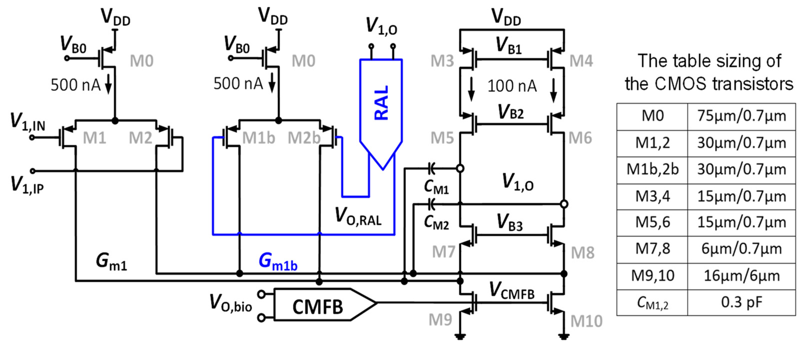
Figure 4 shows the dual cascode amplifier (Gm1) combining with the RAL block. A feedback loop is set up comprising Gm1b, a two-stage chopper amplifier, and the RC-LPF in order to mitigate the output ripple. Figure 4 shows that the input stage consumes a power of 1.2 µW from a supply voltage of 1 V. The global common mode feedback circuit (CMFB) [25], which is used and consumed a biased current of 200 nA from 1 V, is employed to control the DC voltage at the output node of the CCIA. The gates of the transistors M9 and M10 are adjusted using the CMFB circuit (VCMFB) to control the output DC voltage followed to VCM = VDD/2. The power consumption of 1.4 µW of Gm1 including CMFB is used.
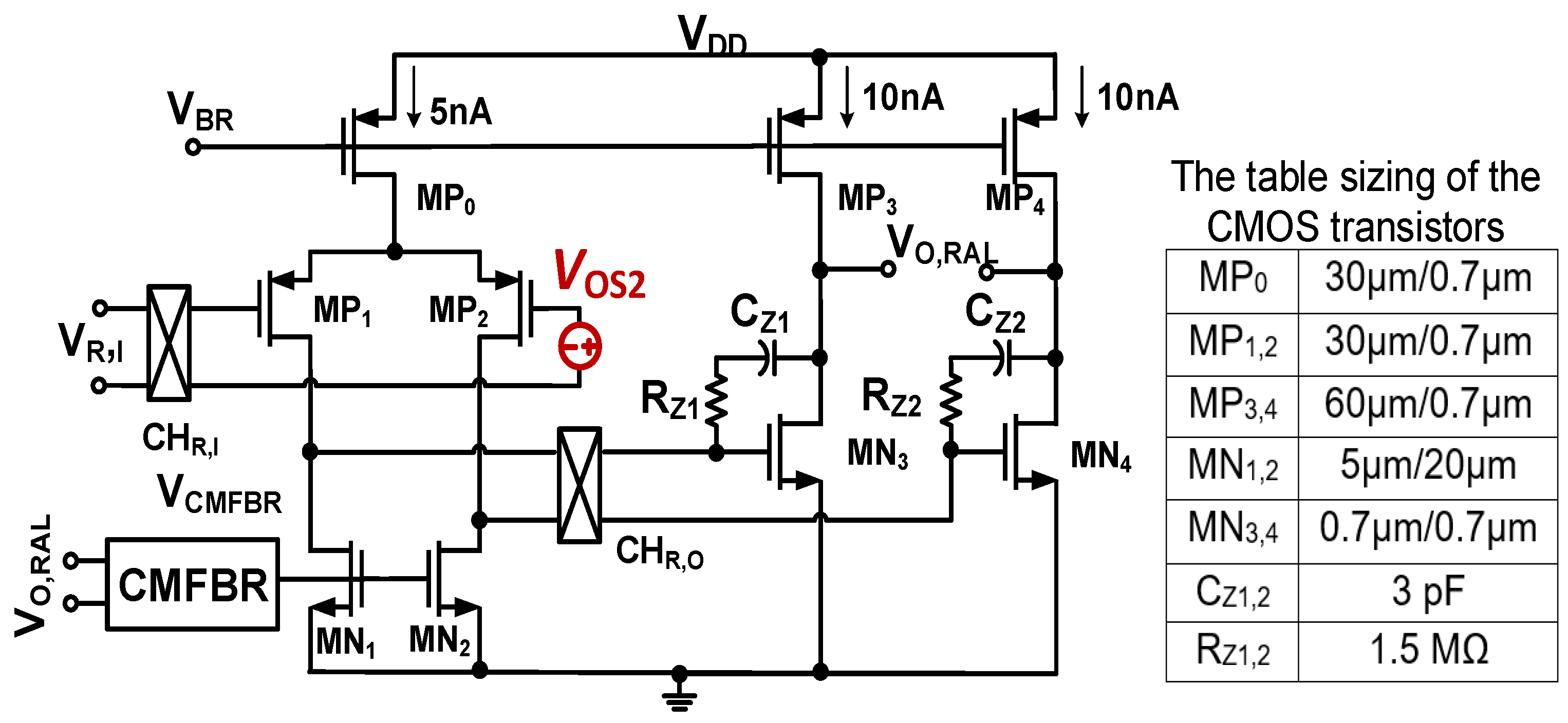
Figure 5 shows the architecture of the chopper two-stage amplifier integrating with a common mode feedback circuit (CMFBR) [25] for Gm2. As already mentioned, the inherent offset VOS2 of Gm2 has the same effect as VOS1; the offset that is also upmodulated creates the ripple at the output of the CCIA. Consequently, it must be eliminated. In RAL, the chopper CHR,I is located at the output of the LPF, while the chopper CHR,O is put between the first and second stage of Gm2. This causes VOS2 to be modulated up to a high frequency and then modulated down by the chopper CHO, resulting in an offset voltage in the front of Gm3. Therefore, VOS2 is considered as an offset at the input of Gm3. Due to the high gain level of Gm1 (about 80 dB), this offset is insignificant compared to the input. Therefore, its influence can be neglected. By using a 1 V supply, the first stage of Gm2 consumes 5 nA, while the second stage of Gm2 is biased to 20 nA for a better swing. The voltage VCMFBR is generated by the CMFB circuit, which uses a bias current of 5 nA. Therefore, the total power of the RAL is only 30 nW.
The DC gain and the cut-off frequency of Gm2 are decisive factors for determining the ripple attenuation factor and the bandwidth of the loop gain. The Monte Carlo simulation (MCS) method is used to study the fluctuation of these parameters across the chip and the mismatch of the device, including global variation and local mismatch. Figure 6a and Figure 6b show the value of the DC gain and cut-off frequency of Gm2, respectively. These distributions were derived from 300 samples of the MCS. The results show a mean value (MV) of the DC gain of Gm2 of 90.9 dB, with a standard deviation (Std) of 0.167 dB. Furthermore, the MV of the cut-off frequency is 0.042 Hz with a Std of 0.0044 Hz.
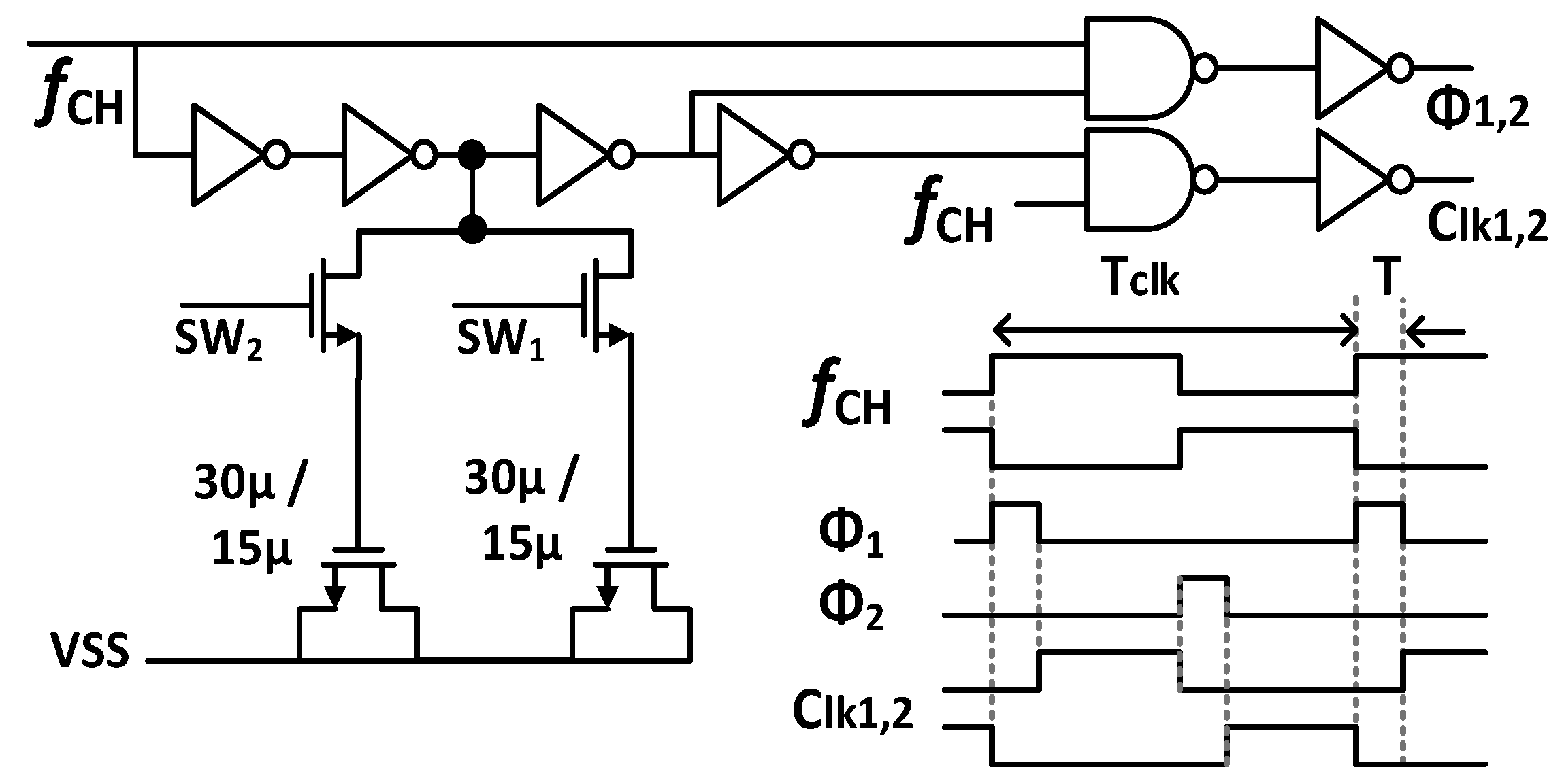
Figure 7 shows the schematic of the Gmb in the IBL. The MP0 and MP1 in Gmb are employed to bias and regulate the buffer with the purpose of reducing the impact of process variation on mismatch devices. The boosted input impedance in IBL can be affected by the pre-charge time T, the switches sizing of Φ1,2, and the buffer design. Figure 8 shows the clock generator for controlling the IBL. The pre-charge time T and Clk1,2 are generated by dividing the clock signal fCH, which can be converted into a delayed signal by the use of several MOS capacitors and inverters. Although using a bias current of 700 nA, IBL is only enabled in 6 μs in each cycle of 100 μs (fCH = 10 kHz); thus, IBL (Gmb) consumes only the current of 700 nA × 6/100 = 42 nA. The size and number of the MOS capacitor are shown in Figure 8. The sizing W/L of the switches SW1,2 is set at about 0.5 µm/0.25 µm in order to minimize the inherent resistance. Furthermore, the pre-charge time T can be altered by using a two-switch SW1,2 in order to mitigate the effect of process variability. This research examines the effect of the pre-charge time T and the size of the switches Φ1,2. Lengthening the pre-charge time T enhances the Zin of the device, while simultaneously amplifying the noise of the device. The size of switches Φ1,2 in Figure 3 is another factor that affects the boost in Zin. A small W/L size can result in a substantial voltage loss between these switches. Figure 9a and Figure 9b show the relationship between the Zin, the input referred noise, the pre-charge time, and the switch sizing, respectively. As can be seen in Figure 9a, the Zin improves from 2.5 MΩ to 0.7–1.8 GΩ when IBL is enabled with the pre-charge time T and is increased from 3 to 6 µs; however, the IRN increases sharply from 1.7 to 2.2 µVrms. As shown in Figure 9b, when the switches sizing (Width-W) of Φ1,2 increases, the parasitic capacitors of these switches are also increased. When clock control for the pre-charge phase is applied to the gate of the CMOS transistor switches, the charge injection noise and clock feed-through increases [26,27], leading to an increase in the IRN. In this work, when the width of the switches sizing of Φ1,2 is changed from 1 to 5 µm, the IRN is increased from 1.8 to 2.1 µVrms, while the noise increases from 2.5 to 3.2 µVrms when W of Φ1,2 changes from 6 to 10 µm. According to the simulated results, as shown in Figure 9, in order to optimize Zin and IRN, the pre-charge time T and the switches sizing Φ1,2 in this design are therefore set to 6 µs and W/L is set to 5 µm/0.5 µm.

4. Simulation Results

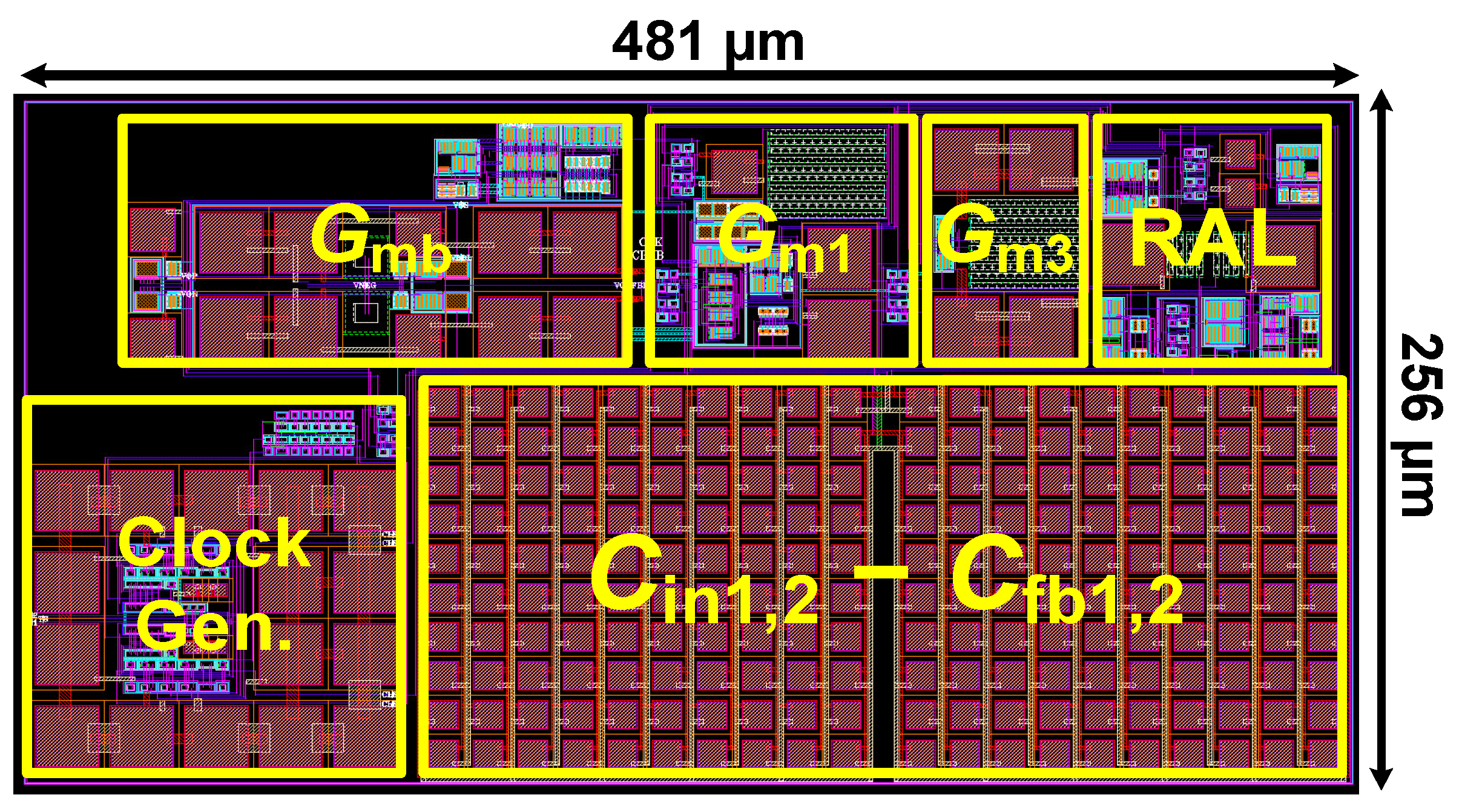
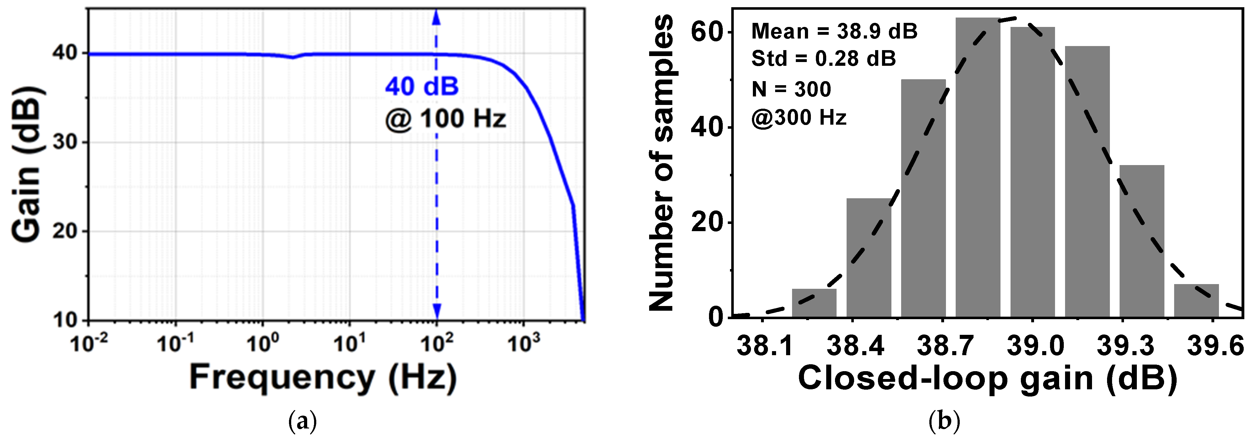
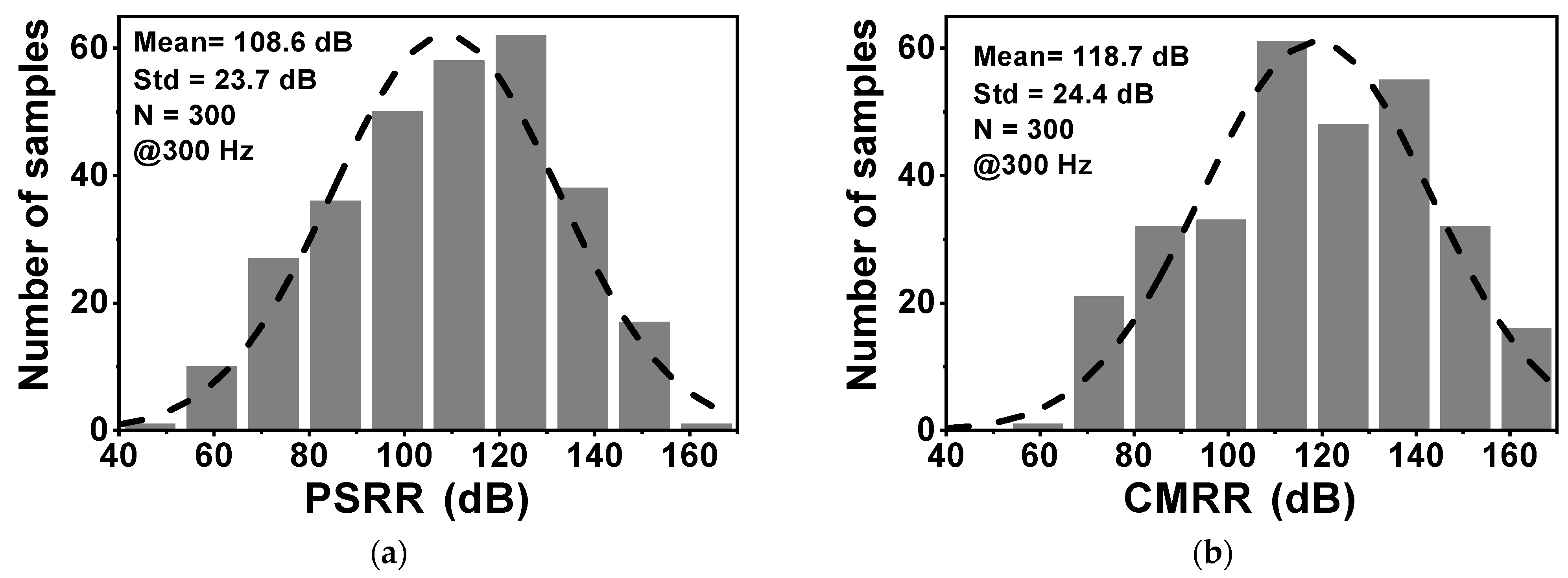
Figure 10 shows the layout of the proposed CCIA in the 180 nm CMOS process. The chip area of the CCIA configuration is 0.123 mm2. Table 1 shows the power dissipation of each block in the CCIA. The total power consumption of the proposed CCIA is 1.87 µW from a VDD of 1 V. Gm1, Gm2, Gm3, and Gmb consume 1400, 30, 400, and 40 nW, corresponding to 74.8%, 1.6%, 21.36%, and 2.24% of the total power consumption, respectively. According to the post-simulation results, it is shown that Figure 11 shows the simulated results of the CCIA’s transfer function—(a) transient; (b) MCs. The CCIA’s Av is 40 dB. The MCS results present that the MV of the closed-loop CCIA gain at 300 samples is 38.9 dB, with a Std of 0.28 dB. Figure 12 shows the MCS results for PSRR and CMRR after running 300 samples. At the 1 V supply, the MV of PSRR and CMRR are 108.6 and 118.7 dB with Stds of 23.7 and 24.4 dB, respectively.
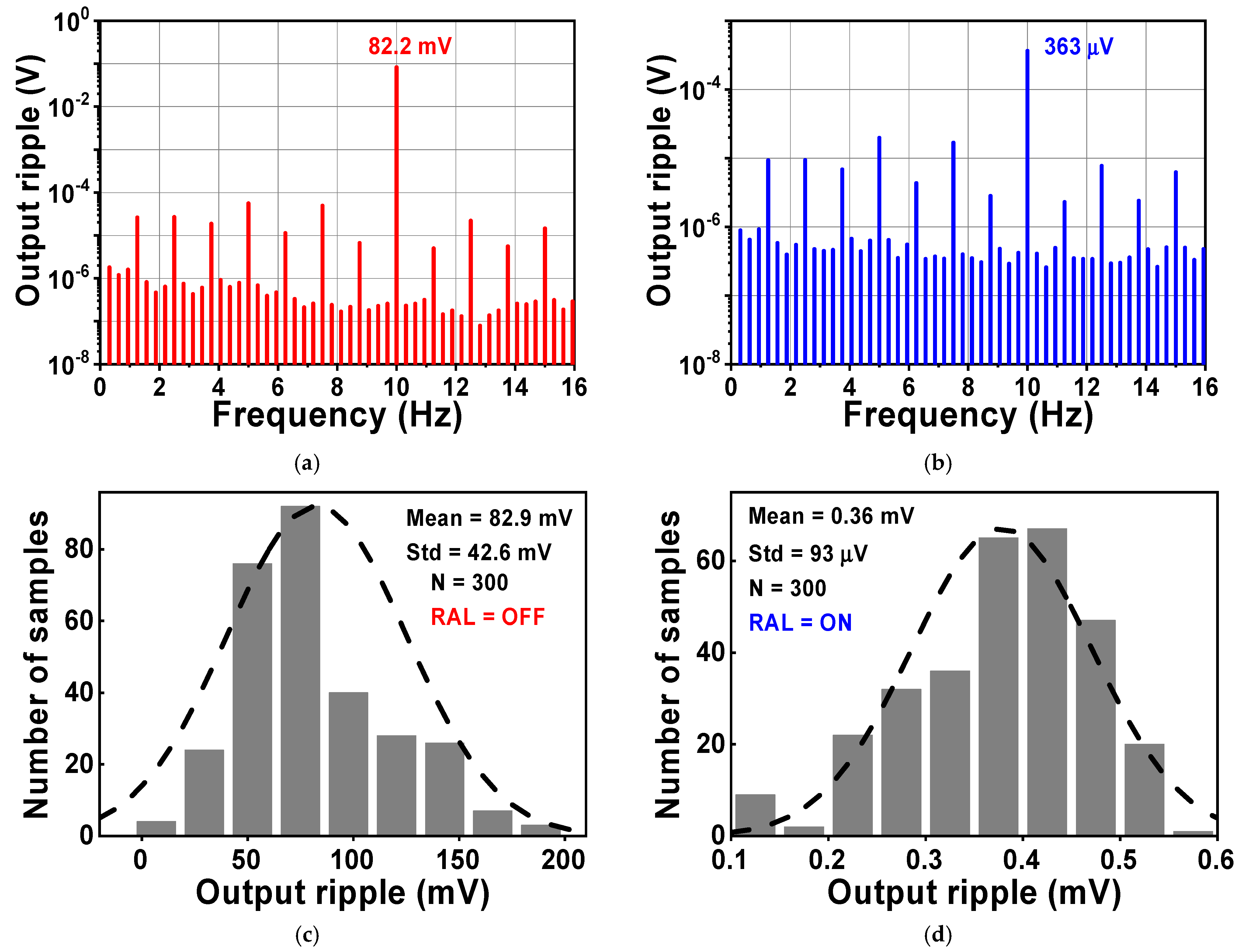
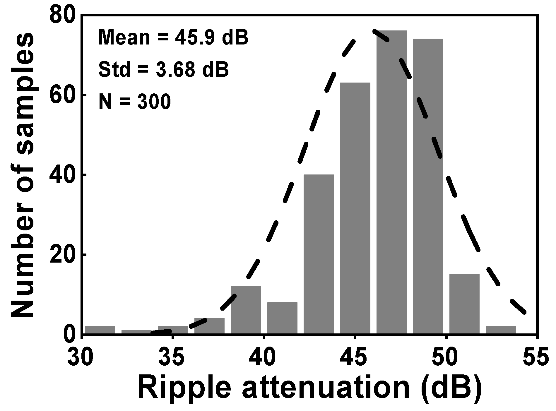
During the simulation, the input of the CCIA is configured so that it is short-circuited in order to test the output spectrum. Both VOS1 and VOS2 were set to a voltage of 5 mV. Figure 13 shows the simulated results of the voltage spectrum and the MCS of the output ripple. When the RAL is disabled, the amplitude of the output spectrum at the chopping frequency is about 82.2 mV, as shown in Figure 13a. The amplitude of the output ripple of the CCIA decreases to 0.36 mV when the RAL is enabled, as shown in Figure 13b. The output ripple is verified using an MCS that includes 300 samples and accounts for both local and global process variations. When the RAL level is changed from off to on, the MV of the output ripple decreases from 82.9 mV to 0.36 mV with a Std of 42.6 mV or 93 µV, as shown in Figure 13c,d. The simulation results shown in Figure 14 therefore give an MV of 45.9 for the ripple attenuation, with a Std of 3.68 dB. The proposed feedback network effectively compensates for the offset voltage (VOS1, VOS2) caused by mismatches due to process, voltage, and temperature variations, resulting in a significant reduction in the output ripple voltage.
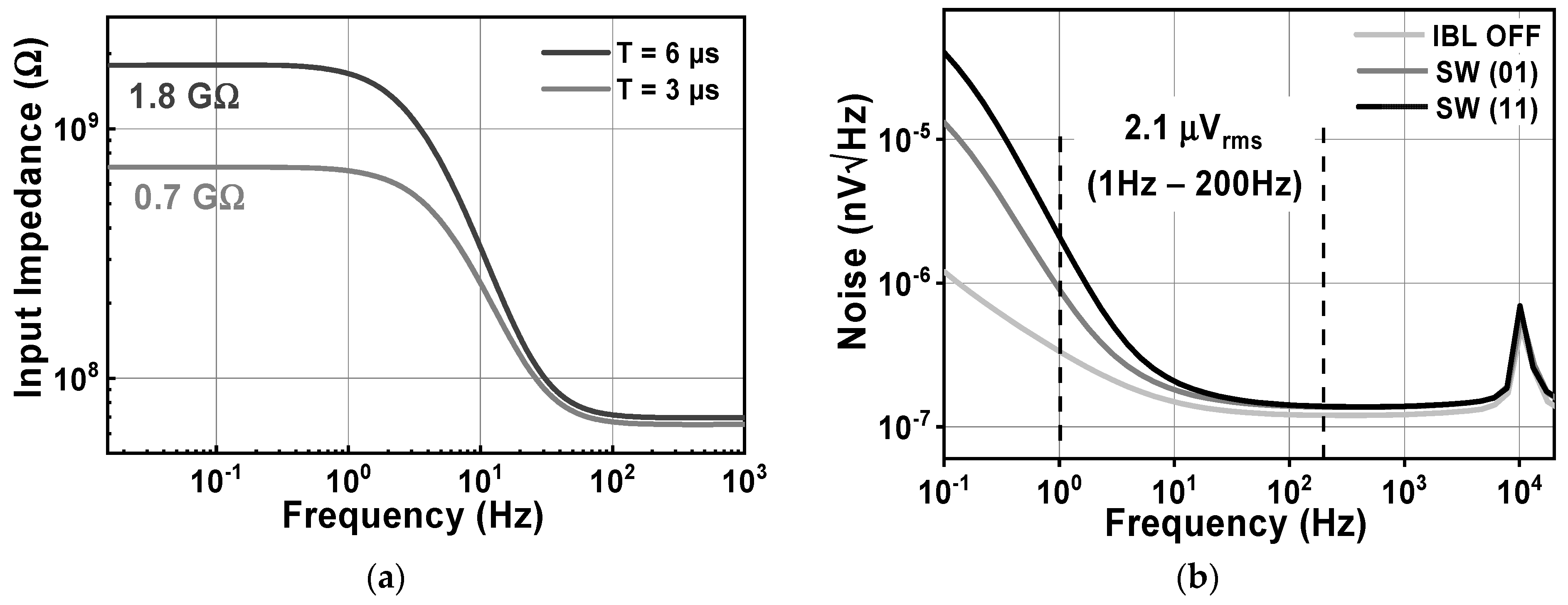
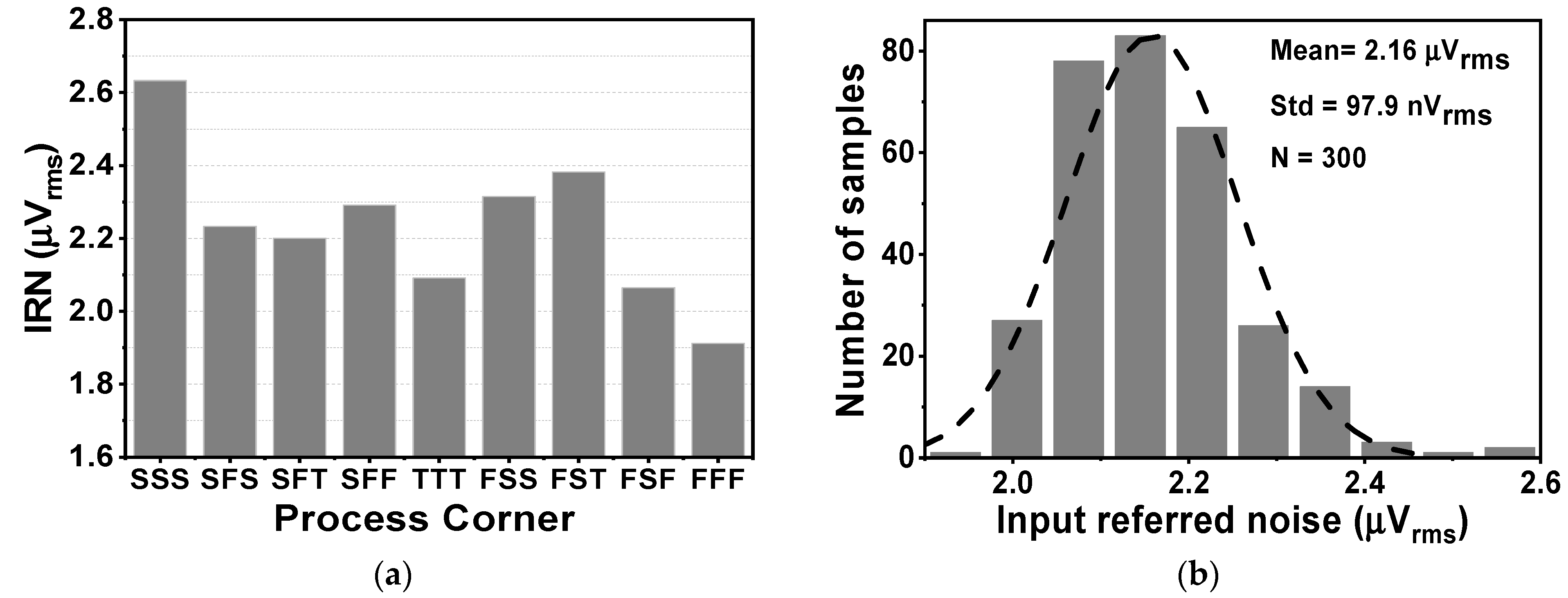
Figure 15 shows the effects of activating the impedance boost loop on the Zin and the input-related noise. By setting the SW1,2 parameter, it is possible to achieve different results for the input impedance. When SW1,2 is set to 01 and 11, corresponding to a pre charge time of 3 and 6 µs, the Zin in the low frequency range increases to about 0.7 and 1.8 GΩ, respectively, as shown in Figure 15a. Without the presence of IBL, the noise floor is about 119 nV/√Hz, while the 1/f corner frequency is 10 Hz. When IBL is enabled, the noise floor increases to 136 nV/√Hz, resulting in an IRN over a bandwidth of 1 to 200 Hz of 2.16 µVrms. This increase is observed for different values of SW1,2, which determines the pulse width of the pre-charge time. Figure 16a shows the variation of IRN for the proposed amplifier across several process corners, ranging from 1.9 to 2.6 µVrms. On the other hand, Figure 16b shows the MV of IRN, which is 2.16 µVrms, with a Std of 97.9 nVrms, verified using an MCS with 300 samples, considering both local and global process variations.
Table 2 shows a brief summary of the primary design specifications, encompassing power consumption, output ripple’s amplitude, Zin, CMRR, PSRR, and NEF (noise efficient factor). There are several references that show simulation results, such as [24,28,29], in order to guarantee an equitable comparison. Table 2 is employed to evaluate the performance of the proposed design in comparison with the current state-of-the-art studies. The proposed CCIA obtains an NEF of about 7.5 by integrating RAL and IBL. Additionally, it exhibits a minimal output ripple of 363 µV and a significant Zin of 1.8 GΩ. The CCIA’s dissipation is 1.87 µW from a 1 V supply.

5. Conclusions

The paper presents a 1.87 µW capacitively coupled chopper instrumentation amplifier for biomedical recording. The output ripple is measured at 0.36 mV, and the input impedance is 1.8 GΩ. The CCIA chip occupies a chip area of only 0.123 mm2 when implemented in a 0.18 µm CMOS technology. The ripple attenuation loop effectively decreases the output ripple of the proposed CCIA down to 0.36 mV. The CCIA is able to achieve a high input impedance of approximately 1.8 GΩ due to the impedance boosting loop. The low-power chopper amplifier has a power dissipation of 1.87 µW at a VDD of 1 V. It also obtains a closed-loop gain of 40 dB, a PSRR of 108.6 dB, and a CMRR of 118.7 dB. The noise floor of the CCIA has a magnitude of 136 nV/√Hz, which leads to an IRN of 2.16 µVrms across a bandwidth of 200 Hz. Thus, an NEF value of 7.5 is attained. This illustrates our ability to evaluate the performance of the proposed CCIA by comparing it to the most recent studies.

Author Contributions

Conceptualization, X.P.T., X.T.P., X.T.K. and M.K.H.; methodology, X.P.T., X.T.K., D.P.P. and M.K.H.; software, X.P.T. and X.T.P.; formal analysis, X.T.K., D.P.P. and M.K.H.; writing—original draft preparation, X.P.T.; writing—review and editing, X.T.K., D.P.P. and M.K.H.; visualization, X.T.P., D.P.P. and M.K.H.; supervision, X.T.K. and M.K.H.; project administration, X.P.T.; funding acquisition, X.P.T., X.T.P., X.T.K. and M.K.H. All authors have read and agreed to the published version of the manuscript.

Funding

This research received no external funding.

Data Availability Statement

The data presented in this study are available in this article.

Conflicts of Interest

The authors declare no conflicts of interest.

References

  1. Tran, X.P.; Pham, X.T.; Kieu, X.T.; Nguyen, L.C.; Pham, D.P.; Hoang, M.K. A 1.8-GΩ Input Impedance 45-dB Ripple Reduction Factor Chopper Amplifier for Biomedical Recording. In Proceedings of the 2023 International Conference on Advanced Technologies for Communications (ATC), Da Nang, Vietnam, 19–21 October 2023. [Google Scholar]
  2. Wang, S.; Koickal, T.J.; Hamilton, A.; Mastropaolo, E.; Cheung, R.; Abel, A.; Smith, L.S.; Wang, L. A Power-Efficient Capacitive Read-Out Circuit With Parasitic-Cancellation for MEMS Cochlea Sensors. IEEE Trans. Biomed. Circuits Syst. 2016, 10, 25–37. [Google Scholar] [CrossRef] [PubMed]
  3. Jiang, X.; Bian, G.-B.; Tian, Z. Removal of artifacts from EEG signals: A review. Sensors 2019, 19, 987. [Google Scholar] [CrossRef] [PubMed]
  4. Lin, C.T.; Ko, L.W.; Chang, M.H.; Duann, J.R.; Chen, J.Y.; Su, T.P.; Jung, T.P. Review of wireless and wearable electroencephalogram systems and brain-computer interfaces-a mini-review. Gerontology 2010, 56, 112–119. [Google Scholar] [CrossRef] [PubMed]
  5. Fiedler, P.; Mühle, R.; Griebel, S.; Pedrosa, P.; Fonseca, C.; Vaz, F.; Zanow, F.; Haueisen, J. Contact Pressure and Flexibility of Multipin Dry EEG Electrodes. IEEE Trans. Neural Syst. Rehabil. Eng. 2018, 26, 750–757. [Google Scholar] [CrossRef] [PubMed]
  6. Nguyen, V.-N.; Pham, X.T.; Lee, J.-W. Three-Step Cyclic Vernier TDC Using a Pulse-Shrinking Inverter-Assisted Residue Quantizer for Low-Complexity Resolution Enhancement. IEEE Trans. Instrum. Meas. 2021, 70, 1–12. [Google Scholar] [CrossRef]
  7. Chandrakumar, H.; Marković, D. A high dynamic-range neural recording chopper amplifier for simultaneous neural recording and stimulation. IEEE J. Solid-State Circuits 2017, 52, 645–656. [Google Scholar] [CrossRef]
  8. Pham, X.T.; Kieu, X.T.; Hoang, M.K. Ultra-Low Power Programmable Bandwidth Capacitively-Coupled Chopper Instrumentation Amplifier Using 0.2 V Supply for Biomedical Applications. J. Low Power Electron. Appl. 2023, 13, 37. [Google Scholar] [CrossRef]
  9. Xu, J.; Lin, Q.; Ding, M.; Li, Y.; Van Hoof, C.; Serdijn, W.; Van Helleputte, N. A 0.6V 3.8μW ECG/bio-impedance monitoring IC for disposable health patch in 40nm CMOS. In Proceedings of the 2018 IEEE Custom Integrated Circuits Conference (CICC), San Diego, CA, USA, 8–11 April 2018. [Google Scholar]
  10. Yaul, F.M.; Chandrakasan, A.P. A noise-efficient 36 nV/√Hz chopper amplifier using an inverter-based 0.2-V supply input stage. IEEE J. Solid-State Circuits 2017, 52, 3032–3042. [Google Scholar] [CrossRef]
  11. Huang, G.; Yin, T.; Wu, Q.; Zhu, Y.; Yang, H. A 1.3μW 0.7μVRMS chopper current-reuse instrumentation amplifier for EEG applications. In Proceedings of the 2015 IEEE International Symposium on Circuits and Systems (ISCAS), Lisbon, Portugal, 24–27 May 2015. [Google Scholar]
  12. Wu, R.; Makinwa, K.A.A.; Huijsing, J.H. A Chopper Current-Feedback Instrumentation Amplifier With a 1 mHz 1/f Noise Corner and an AC-Coupled Ripple Reduction Loop. IEEE J. Solid-State Circuits 2009, 44, 3232–3243. [Google Scholar] [CrossRef]
  13. Park, J.H.; Tang, T.; Zhang, L.; Ng, K.A.; Gammad, G.G.L.; Yen, S.C.; Yoo, J. A 15-Channel Orthogonal Code Chopping Instrumentation Amplifier for Area-Efficient, Low-Mismatch Bio-Signal Acquisition. IEEE J. Solid-State Circuits 2020, 55, 2771–2780. [Google Scholar] [CrossRef]
  14. Nasseriana, M.; Peiravia, A.; Moradi, F. A fully-integrated 16-channel EEG readout front-end for neural recording applications. AEU—Int. J. Electron. Commun. 2018, 94, 109–121. [Google Scholar] [CrossRef]
  15. Li, J.; Zhu, L.; Su, R.; Wang, W.; Zhou, Y.; Xie, S.; Mao, G.; Zhou, Z. A Capacitively Coupled Chopper Instrumentation Amplifier With Deadtime Offset Reduction Technique for Neural Signal Sensing. IEEE Sens. Lett. 2024, 8, 1–4. [Google Scholar] [CrossRef]
  16. Zheng, J.; Ki, W.-H.; Hu, L.; Tsui, C.-Y. Chopper capacitively coupled instrumentation amplifier capable of handling large electrode offset for biopotential recordings. IEEE Trans. Circuits Syst. II Express Briefs 2017, 64, 1392–1396. [Google Scholar] [CrossRef]
  17. Wu, J.; Law, M.K.; Mak, P.I.; Martins, R.P. A 2-µW 45-nV/√Hz readout front end with multiple-chopping active-high-pass ripple reduction loop and pseudo feedback DC servo loop. IEEE Trans. Circuits Syst. II Express Briefs 2016, 63, 351–355. [Google Scholar]
  18. Chandrakumar, H.; Marković, D. An 80-mVpp Linear-Input Range, 1.6- GΩ Input Impedance, Low-Power Chopper Amplifier for Closed-Loop Neural Recording That Is Tolerant to 650-mVpp Common-Mode Interference. IEEE J. Solid-State Circuits 2017, 52, 2811–2828. [Google Scholar] [CrossRef]
  19. Zheng, J.; Ki, W.H.; Tsui, C.Y. Analysis and design of ripple reduction chopper bandpass amplifier. IEEE Trans. Circuits Syst. I Reg. Pap. 2018, 65, 1185–1195. [Google Scholar] [CrossRef]
  20. Chandrakumar, H.; Marković, D. A simple area-efficient ripple rejection technique for chopped biosignal amplifiers. IEEE Trans. Circuits Syst. II Express Briefs 2015, 62, 189–193. [Google Scholar] [CrossRef]
  21. Fang, L.; Gui, P. A Low-Noise Low-Power Chopper Instrumentation Amplifier With Robust Technique for Mitigating Chopping Ripples. IEEE J. Solid-State Circuits 2022, 57, 1800–1811. [Google Scholar] [CrossRef]
  22. Luo, D.; Zhang, M.; Wang, Z. A Low-Noise Chopper Amplifier Designed for Multi-Channel Neural Signal Acquisition. IEEE J. Solid-State Circuits 2019, 54, 2255–2265. [Google Scholar] [CrossRef]
  23. Wenfei, C.; Yi, L.; Shubin, L.; Ling, W.; Rui, M.; Zhangming, Z. A 2.6 GΩ, 1.4 μVrms current-reuse instrumentation amplifier for wearable electrocardiogram monitoring. Microelectron. J. 2021, 107, 1049. [Google Scholar]
  24. Chen, X.; Mo, T.; Wu, P.; Wu, B. A Capacitive-Feedback Amplifier with 0.1% THD and 1.18 μVrms Noise for ECG Recording. Electronics 2024, 13, 378. [Google Scholar] [CrossRef]
  25. Baker, R.J. CMOS Circuit Design, Layout, and Simulation; Wiley: Hoboken, NJ, USA, 2010. [Google Scholar]
  26. Xu, J.; Fan, Q.; Huijing, J.H.; Hoof, C.V.; Yazicioglu, R.F.; Makinwa, K.A.A. Measurement and Analysis of Current Noise in Chopper Amplifiers. IEEE J. Solid-State Circuits 2013, 48, 1575–1584. [Google Scholar]
  27. Ha, H.; Hoof, C.V.; Helleputte, N.V. Measurement and Analysis of Input-Signal Dependent Flicker Noise Modulation in Chopper Stabilized Instrumentation Amplifier. IEEE Solid-State Circuits Lett. 2018, 4, 90–93. [Google Scholar] [CrossRef]
  28. Pham, X.T.; Vu, T.K.; Nguyen, T.D.; Pham-Nguyen, L. A 1.2-µW 41-dB Ripple Attenuation Chopper Amplifier Using Auto-Zero Offset Cancelation Loop for Area-Efficient Biopotential Sensing. Electronics 2022, 11, 1149. [Google Scholar] [CrossRef]
  29. Xu, W.; Wang, T.; Wei, X.; Yue, H.; Wei, B.; Duan, J.; Li, H. Low Noise, High Input Impedance Digital-Analog Hybrid Offset Suppression Amplifier for Wearable Dry Electrode ECG Monitoring. Electronics 2020, 9, 165. [Google Scholar] [CrossRef]
  30. Sawigun, C.; Thanapitak, S. A Compact Sub-µW CMOS ECG Amplifier With 57.5-MΩ Zin, 2.02 NEF, 8.16 PEF and 83.24-dB CMRR. IEEE Trans. Biomed. Circuits Syst. 2021, 15, 549–558. [Google Scholar] [CrossRef]
  31. Chen, M.; Chun, H.S.; Castro, I.D.; Torfs, T.; Lin, Q.; Van Hoof, C.; Wang, G.; Lian, Y.; Van Helleputte, N. A 400 GΩ Input-Impedance Active Electrode for Non-Contact Capacitively Coupled ECG Acquisition With Large Linear-Input-Range and High CM-Interference-Tolerance. IEEE Trans. Biomed. Circuits Syst. 2019, 13, 2. [Google Scholar] [CrossRef]
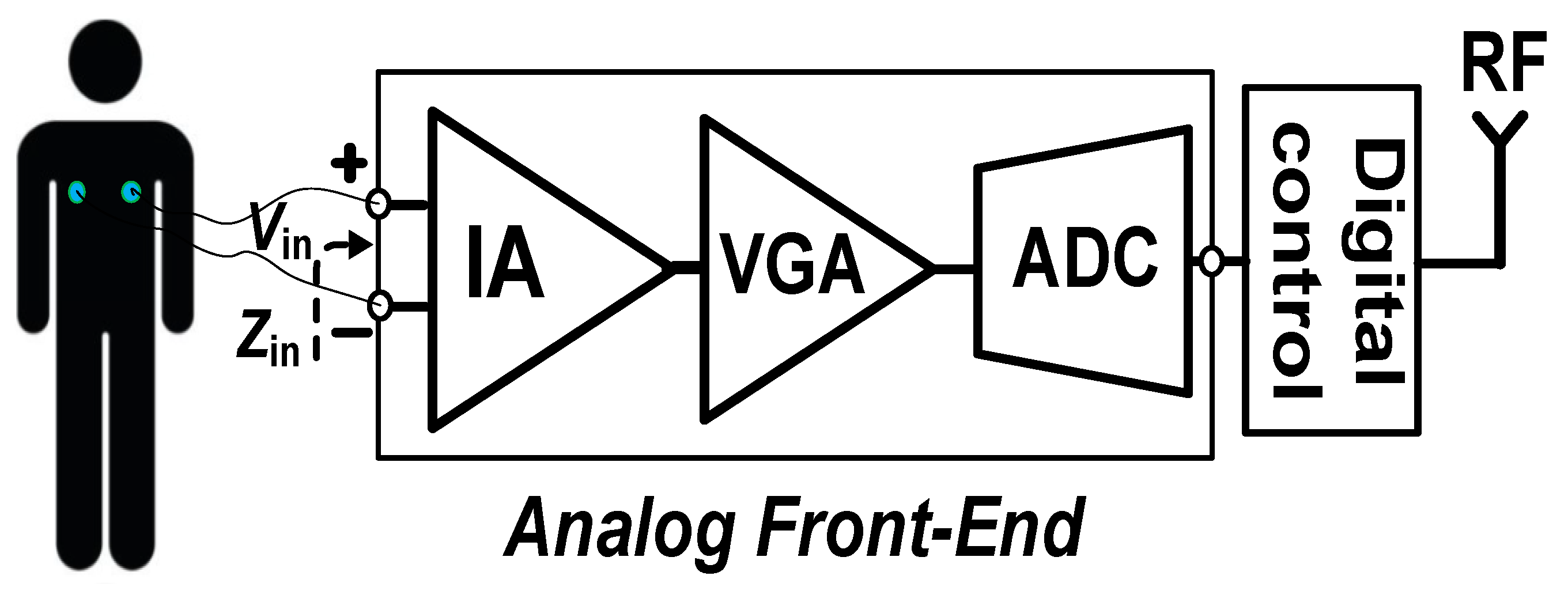
Figure 1. System architecture of a typical wireless sensor biomedical system.
Jlpea 14 00037 g001
Figure 2. The schematic of the proposed CCIA with the spectrum of signal corresponding to each node.
Jlpea 14 00037 g002
Figure 3. Schematics of the IBL and time diagram of the CCIA.
Jlpea 14 00037 g003
Figure 4. Schematic of the two-folded cascode opamp Gm1 with table sizing of CMOS transistors.
Jlpea 14 00037 g004
Figure 5. Schematic of the chopper two-stage amplifier with table sizing of CMOS transistors.
Jlpea 14 00037 g005
Figure 6. Monte Carlo simulation results for (a) DC gain, and (b) cut-off frequency of Gm2.
Jlpea 14 00037 g006
Figure 7. The schematic of the circuit in IBL with table sizing of the CMOS transistors.
Jlpea 14 00037 g007
Figure 8. Schematic of a signal control generator for IBL.
Jlpea 14 00037 g008
Figure 9. The relation between input impedance and noise to (a) the pre-charge time, and (b) the switches sizing.
Jlpea 14 00037 g009
Figure 10. The layout of the proposed CCIA.
Jlpea 14 00037 g010
Figure 11. (a) The transient of the proposed CCIA’s transfer function; (b) MCS result of the proposed CCIA’s transfer function.
Jlpea 14 00037 g011
Figure 12. The MCS results of (a) PSRR; (b) CMRR.
Jlpea 14 00037 g012
Figure 13. The simulated results of the voltage spectrum and MCS of the output ripple when RAL (a,c) is disabled, or (b,d) enabled.
Jlpea 14 00037 g013
Figure 14. The MCS of the ripple attenuation result.
Jlpea 14 00037 g014
Figure 15. The simulated results of (a) the CCIA’s input impedance; (b) the CCIA’s noise.
Jlpea 14 00037 g015
Figure 16. The simulated result of (a) the CCIA’s noise across several the process corners and (b) the CCIA’s noise.
Jlpea 14 00037 g016
Table 1. The power dissipation of each block of the proposed CCIA.
BlockCircuitComponentsPower Dissipation (nW)
Dual_FC (Gm1)OPA-Dual FCDifferential Pair500
Differential Pair500
Cascode Branches200
CMFB 200
CS (Gm3)OPA-CSCommon source400
RAL (Gm2)Stage-1Differential Pair5
Stage-2Common source20
CMFB2 5
IBL (Gmb)Buffer 42
Total1872
Table 2. Performance comparison.
Ref.[18] [23] [24][28][29] [30] [31] This Work
Year20172021202420222020202120192024
Power (µW)25.941.51.2119.80.6721.21.87
Supply (V)1.21.82.4711.8251
Output ripple (mV)0.012NANA0.061NANANA0.36
Ripple Attennuation (dB)NANANA>41NANANA45.9
Zin (GΩ)0.32.6NANA2.10.05754001.8
Gain (dB)25.74059.7404640.62040
PSRR (dB)NA85>7087NA84.2N/A108.6
CMRR (dB)NA93>871089683.24>70118.7
IRN (µVrms)91.41.181.81.92.013.72.16
NEF7NA2.135.4NA2.63NA7.5
Tech. (nm)40180130180180350180180
Meas./Sim.Meas.Meas.Sim.Sim.Sim.Meas.Meas.Sim.
Disclaimer/Publisher’s Note: The statements, opinions and data contained in all publications are solely those of the individual author(s) and contributor(s) and not of MDPI and/or the editor(s). MDPI and/or the editor(s) disclaim responsibility for any injury to people or property resulting from any ideas, methods, instructions or products referred to in the content.