Article

A Robotic Eye Gaze Mirroring System for Human–Robot Interaction: Evaluating Response Time Across Proxemic Distances


by
Jun Wei Mok
,
Prabakaran Veerajagadheswar
* and
Mohan Rajesh Elara
Engineering Product Development, Singapore University of Technology and Design, Singapore 487372, Singapore
*
Author to whom correspondence should be addressed.
Systems 2026, 14(2), 206; https://doi.org/10.3390/systems14020206
Submission received: 9 December 2025 / Revised: 9 February 2026 / Accepted: 12 February 2026 / Published: 15 February 2026
(This article belongs to the Section Artificial Intelligence and Digital Systems Engineering)

Abstract

Robots are increasingly becoming part of everyday social environments. Among the different types of communication cues, eye gaze in the context of human–robot interactions (HRIs) fosters connection and engagement. Although gaze behavior has been extensively studied, most existing research assumes a fixed interaction distance and often does not account for variations in proxemic distance that influence the perceptions of gaze. While prior studies have developed robotic eye gaze systems capable of producing natural gaze behaviors, these systems are usually evaluated at fixed interaction distances. Comparatively, less attention has been given to measuring the impact of proxemic distance on gaze mirroring. This study introduces a gaze mirroring system that integrates 3D robotic eyes with a mobile robot to track human gaze across various proxemic distances. This paper presents the system’s mechanical design and implementation, as well as the evaluation of its tracking performance. Experiments on the system were conducted across Hall’s proxemic zones, intimate, personal, and social, under static, teleoperated, and integrated movement conditions. The results demonstrate that the proposed system achieves highly efficient tracking with response times that fall within established thresholds for natural gaze timing in human–robot interaction.

1. Introduction

Human mimic robots are no longer a distant concept and have moved beyond research labs. Today they are prevalent in homes [1], schools [2], hospitals [3], public spaces [4] and even within the hospitality industry [5]. This change is happening due to improved capabilities in sensing and machine learning, and the increased demand for robots to support education, therapy, and assistance [2,6,7]. As these robots transition from prototypes to everyday companions and assistants, their ability to consistently demonstrate human-like social behaviors is essential for user acceptance. Empirical work has shown that people treat robots as social partners in many contexts, disclosing personal information to robots, interacting with them in caregiving scenarios, and including them in educational routines [2,8].
This shift demands a fundamental rethinking of robot design. While early robot designs were previously evaluated mainly on task efficiency and performance, it is now essential to account for nuanced socio-communicative factors, such as timing, expressiveness, and spatial behavior, that shape users’ perceptions of intent [9]. As robots assume social roles, design considerations must extend beyond just the “what” of the actions they perform, but to also consider the “how” and “when” of those actions.
Eye gaze can be used to coordinate attention, signal intent, and establish rapport, making it a fundamental social communication mode in human–robot interaction (HRI) that influences perceived attentiveness and engagement [6,10]. Studies have shown that robots with appropriate gaze behavior show improved collaboration, faster task completion, and higher ratings of naturalness and competence [11,12]. The “how” and the “when” of robots’ gaze while performing these tasks are essentially the key [13,14].
Attention mechanisms in social robotics have been investigated as methods used to regulate perception, turn-taking and engagement. Previous research has explored attention modeling utilizing multimodal cues, such as the use of gaze, head orientation and saliency, to facilitate socially responsive robot behaviors [10,15,16].
Comprehensive reviews have identified various types of communication involving the use of eye gaze, with some incorporating speech and gestures. There are even more nuanced types of gaze behaviors, such as gaze aversions and expressive gaze. This reflects the development and progress in this field over the past decades [10].
Based on the literature, Table 1 categorizes the communicative modes of eye gaze in HRI. While acknowledging that gaze behaviors may overlap in practice, these modes are organized by the dominant communicative function.
The recent literature has shown that gaze-contingent and gaze-responsive interfaces improve engagement, coordination, and perceived responsiveness [11,20,23,24]. In these systems, a robot’s gaze tracks a human’s visual attention in real time which closes the perception–action loop between human and robot. These studies emphasize the role of synchronization in gaze-based interaction, which this study aims to tackle by using response time as a parameter.
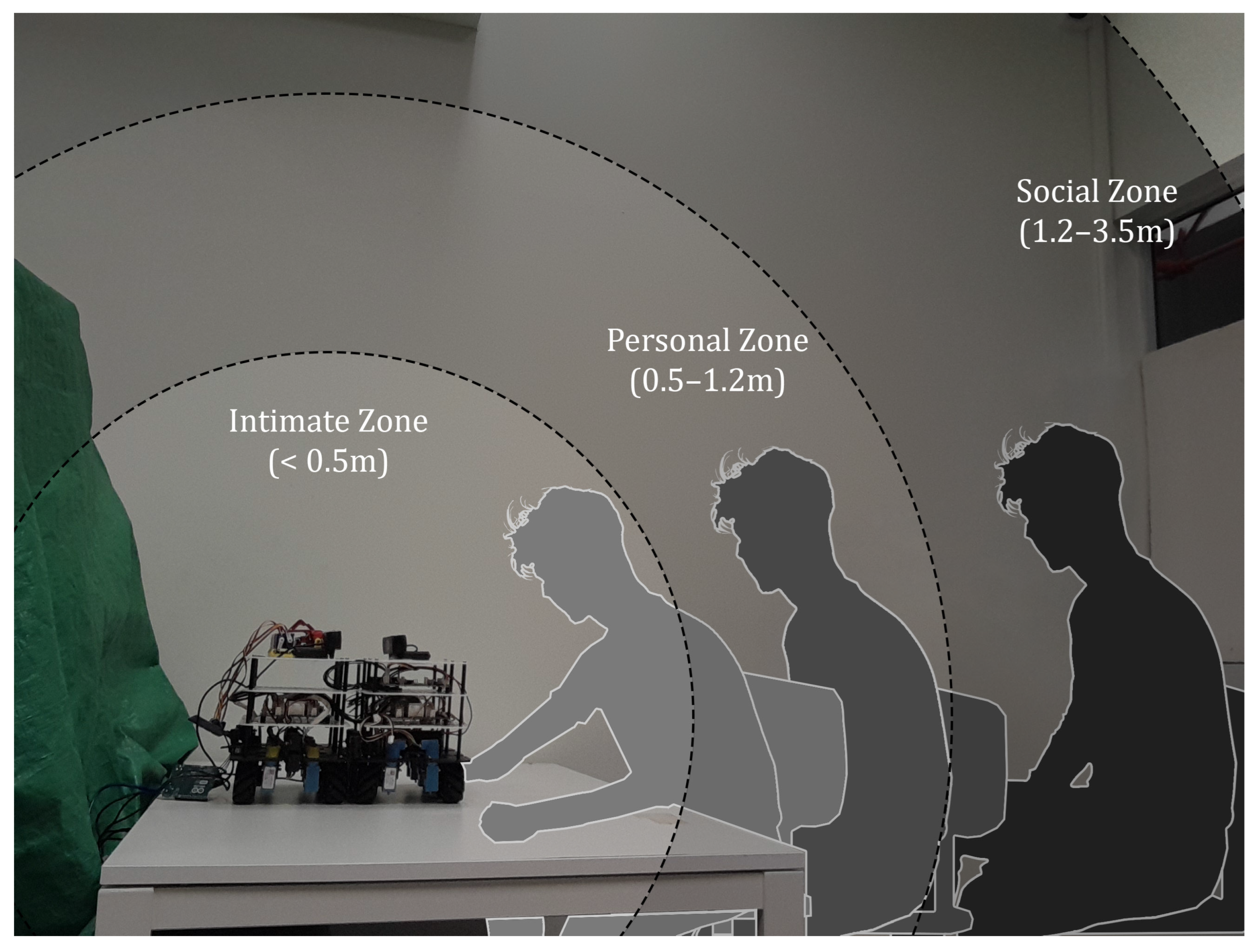
Gaze and interpersonal distance are both important aspects for social communication. Proxemics, which is the study of interpersonal distance and its communicative effects, has a longstanding tradition in social psychology. Based on Hall’s (1966) framework [25], there are four interaction zones: intimate (<0.5 m), personal (0.5–1.2 m), social (1.2–3.5 m), and public (>3.5 m). Interpersonal distance plays an important role in affective and behavioral responses. At close ranges, the use of gaze amplifies arousal and intimacy. Conversely, at greater distances, the impact of gaze is diminished and is more likely to be interpreted as a sign of attentiveness [26,27,28].
Within human–robot interaction (HRI), proxemics research has primarily focused on navigation, path planning, and comfort distances [7,29]. In contrast, studies examining gaze typically use fixed distances, of about one meter [11,30]. A review on human–robot proxemics note that most robotics proxemics research focuses on spatial management, such as the appropriate distance of how close a robot should be, while giving comparatively less attention to how robots communicate intent or through other nonverbal cues [31]. The result is that robots may position itself and maintain the appropriate distances but yet, not necessarily communicating effectively through eye contact. Studies have shown that direct mutual gaze at intimate distances can provoke anxiety or avoidance if not properly modulated, whereas at social distances, too short of a gaze duration may be perceived as inattentiveness [32].
Table 2 presents key studies on proxemics in human–robot interaction (HRI), categorized according to the main areas of focus along with the findings. While many of the works show that gaze influences spatial comfort and interpersonal dynamics, a gap still remains in examining how proxemics, and gaze behavior are interconnected components of communication between human and robots.
Some of these findings are noteworthy to this research. In one study it was noted that interaction with robots in tighter or more confined spaces made people feel stressed and uneasy. While the study only focused on the environmental factors, it reinforces the broader principle that the spatial environment shaped how people perceived the behavior of robots as well [37].
In another study, Gaussian functions were mapped to Hall’s interpersonal zones [25], which guide the robots’ trajectory through crowded spaces. The system maintained comfortable distances and safety by taking into account orientation and group cues [29]. By solely relying on spatial cues, however, there was still an opportunity to incorporate gaze or facial feedback.
These findings still highlight a critical gap. While proxemics research informs where a robot should position itself and gaze research defines the direction in which a robot should look, there is still an opportunity for developing a unified framework that integrates proxemics with gaze-contingent attention mechanisms to guide gaze behavior across different interpersonal distances. This would thus allow robots to sustain natural interactions.
This research looks at response time as an important factor to obtain naturalness in human–robot interaction. Response time is defined as the brief delay between the input action of a user and the robot’s response. The process for this is that the robot must process the input action and respond appropriately within a short timeframe to achieve naturalness in its communication. Table 3 shows the response time benchmarks based on existing studies. These values are drawn from both the human–human interaction (HHI) and human–robot interaction (HRI) literature. HHI benchmarks reflect biological and perceptual constraints, while HRI benchmarks provide empirically grounded reference ranges for interpreting robot gaze behavior.
Gaze responses faster than 50 ms are perceived to be seamless and continuous to humans [40,41]. Typical human saccadic gaze reaction times are between 150 and 250 ms [42,43]. Response times of 200 ms have been shown to be related to responsive head or gaze behaviors; actions within this window are perceived as natural and socially contingent [44]. Response times within 500 ms are perceived to be behavior that is seen as attentive and intentional [10,11,28]. Response times of 1000 ms continue to convey clear intention and are generally acceptable for tasks involving collaborative interaction. It is at the upper limit for interaction to be perceived as natural [10,28].
A response time of 2000 ms is the boundary at which coordinated movements become noticeably harder to synchronize. A study found that a subject interacting with a robot that had a 2000 ms response time would rely less on real-time feedback and more on prediction [44]. A response time of 4000 ms reduces gaze-to-hand following behavior and leads to a loss of coordination [45], while a 10,000 ms delay can disrupt engagement entirely [45].
Response time demands become even more pronounced when considering proxemics. At intimate distances, people are highly sensitive to micro-delays in gaze responses, requiring near-synchronous timing. At social distances, lower visual resolution, noise, and lighting variation increase computational demands and make detection harder, while servo inertia and mechanical factors contribute to increased actuation delay. Designing a gaze system based on proxemics, therefore, requires optimizing detection and actuation to achieve natural gaze behaviors across varying proxemic distances.
Although gaze communication and response timing have been widely studied, existing work has primarily evaluated gaze behavior at fixed interaction distances. Comparatively, less attention has been given to measuring the impact of proxemic distance on gaze mirroring.
In the context of this study, response time will not be treated as a fixed threshold, but will be used as a parameter that can be interpreted on how gaze behavior may be perceived. Lower response time values are associated with natural or socially contingent gaze behavior, while higher values may still support attentive, intentional, or collaborative interaction. Hence, experiments will be conducted to examine multiple operating conditions to demonstrate the system functioning across a range of contexts against established perceptual benchmarks, rather than to meet prescriptive targets. The response time benchmarks will be used as technical reference points to give context to the measured response times and not substitute for the perceptual validation of social comfort or subjective naturalness.
This study develops and evaluates an eye gazing system that consists of a robotic eye assembly driven by servo motors mounted on a Smorphi robot base. Sensing is achieved using a primary webcam for human landmark detection and a secondary observer camera for physical eye validation. The detection pipeline uses the MediaPipe Face Mesh to extract key facial landmarks, including the nose, ears, eye iris, inner and outer corners of the eyes, and mouth corners. From this, a normalized horizontal gaze value (0.0–1.0) is computed and transmitted to the microcontroller for actuation [46].
The system’s performance was evaluated according to Hall’s proxemic zones [25], intimate (<0.5 m), personal (0.5–1.2 m), and social (1.2–3.5 m), and also under three operating conditions: static operation, teleoperated movement, and integrated gaze mirroring. Two technical metrics were measured, the response time between detection and actuation and the correspondence between commanded and observed eye positions to provide evidence of how timing affects a robot’s ability to use gaze in communication.
An overview of the gaze mirroring system is illustrated in Figure 1. Three key contributions are made. First, this system demonstrates a proof of concept for a real-time gaze mirroring system that utilizes facial landmarking detection with a 3D robotic eye mechanism. Second, it provides empirical data and compares across different proxemic zones, showing how response time varied with distance. Third, it provides insights into engineering factors such as distance, robot motion, and the impact of mechanical friction on robotic gaze systems.
By linking perceptual constraints (timing and distance), social theory (proxemics), and engineering practice (real-time perception-to-actuation control), this work provides the technical infrastructure needed to bridge two research streams that have largely been studied separately. The result is an engineering pathway for robots that can not only position themselves appropriately in space but also achieve natural gaze behavior across different proxemic distances.

2. System Architecture of the Robotic Eye

The main objective of this paper is to develop a robotic eye gazing system that can track and mirror human gaze and to assess its response time across different proxemic distances. The proposed system consists of a 3D robotic eye system integrated with a modular robotic platform. This section will introduce the mechatronic system of the robotic eye, modular robotic platform, and the system integration of both the eye and the robot.

2.1. Robotic Eye Mechanism

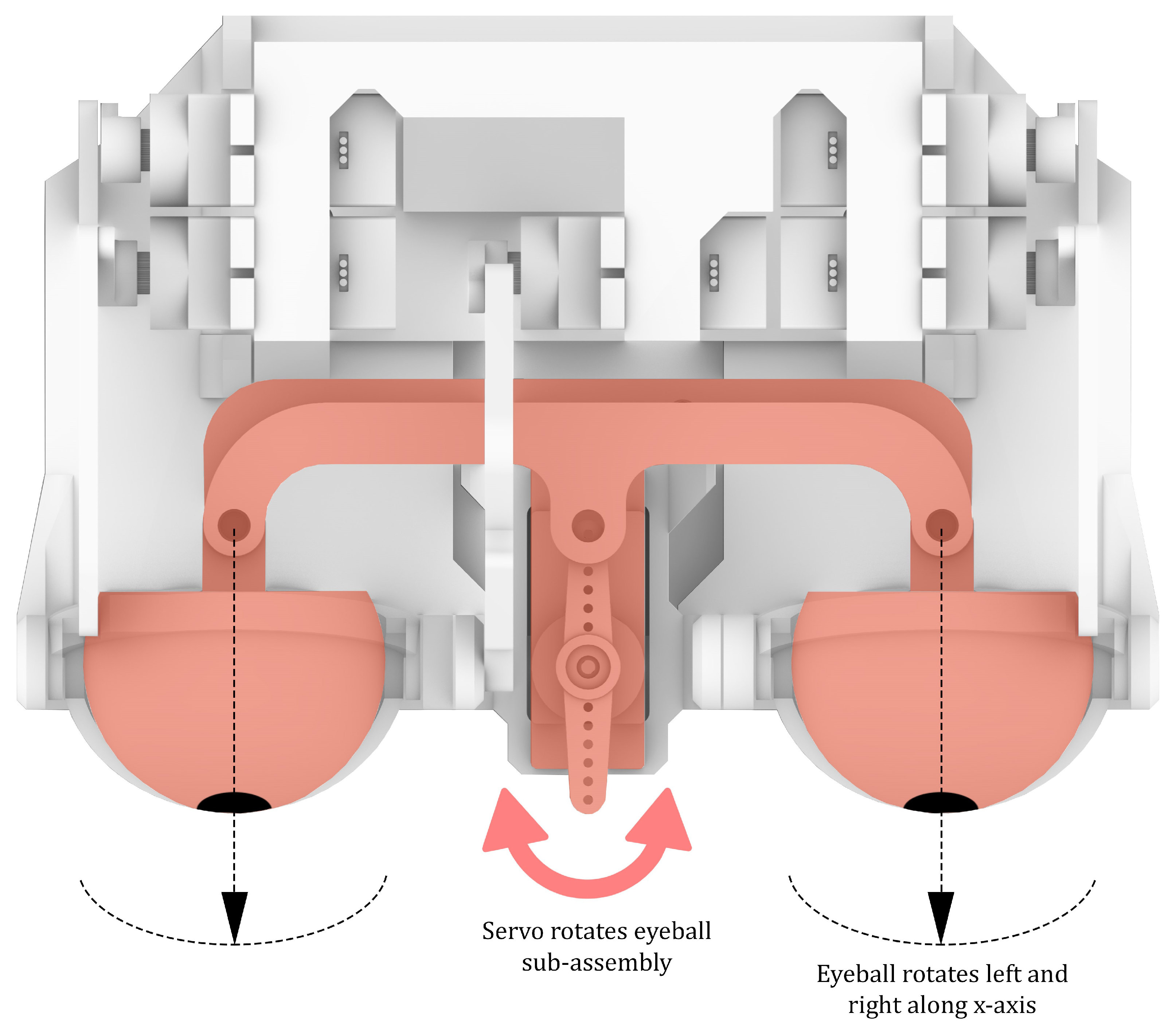
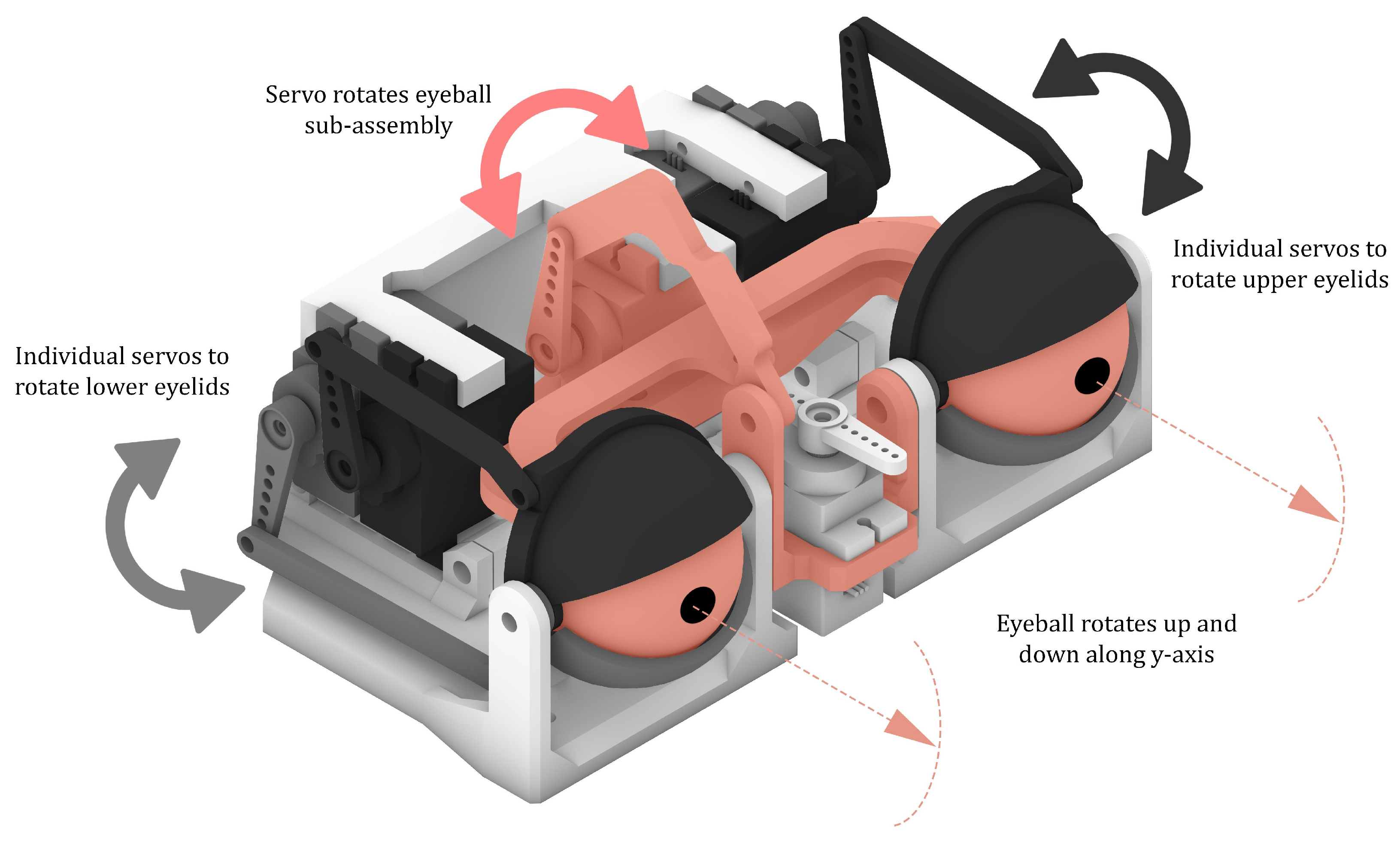
The mechanical parts of the 3D robotic eyes are made from 3D-printed components and the pair of eyes are connected to a total of 6 servos. The eyeballs are mounted on a sub-assembly that consists of a series of connectors, arms and adaptors and hosted within the eyeball socket, forming a sub-assembly. This sub-assembly allows rotation along the x-axis for left and right motion that is controlled by an individual servo and the y-axis for up and down movement, also controlled by another independent servo. Four individual servos are used for each eyelid to manage the blinking movement. This allows natural blinks, partial eyelid opening and closing, and potentially the incorporation of emotional gestures, which were coded in Arduino, and the design allows for synchronized or independent eyelid movement. The entire mechanism is enclosed in a rigid modular frame which was aligned and manually assembled and the design allowed for easy access for maintenance or replacement of parts. Figure 2 and Figure 3 depict the mechanical layout, clearly highlighting the sub-assemblies that are connected to individual servos that actuate the eyeballs and eyelids. Although the system supports eyelid actuation, it was a feature that was not activated in the present study to avoid introducing additional variables.

2.2. Robotic Eye Electrical System

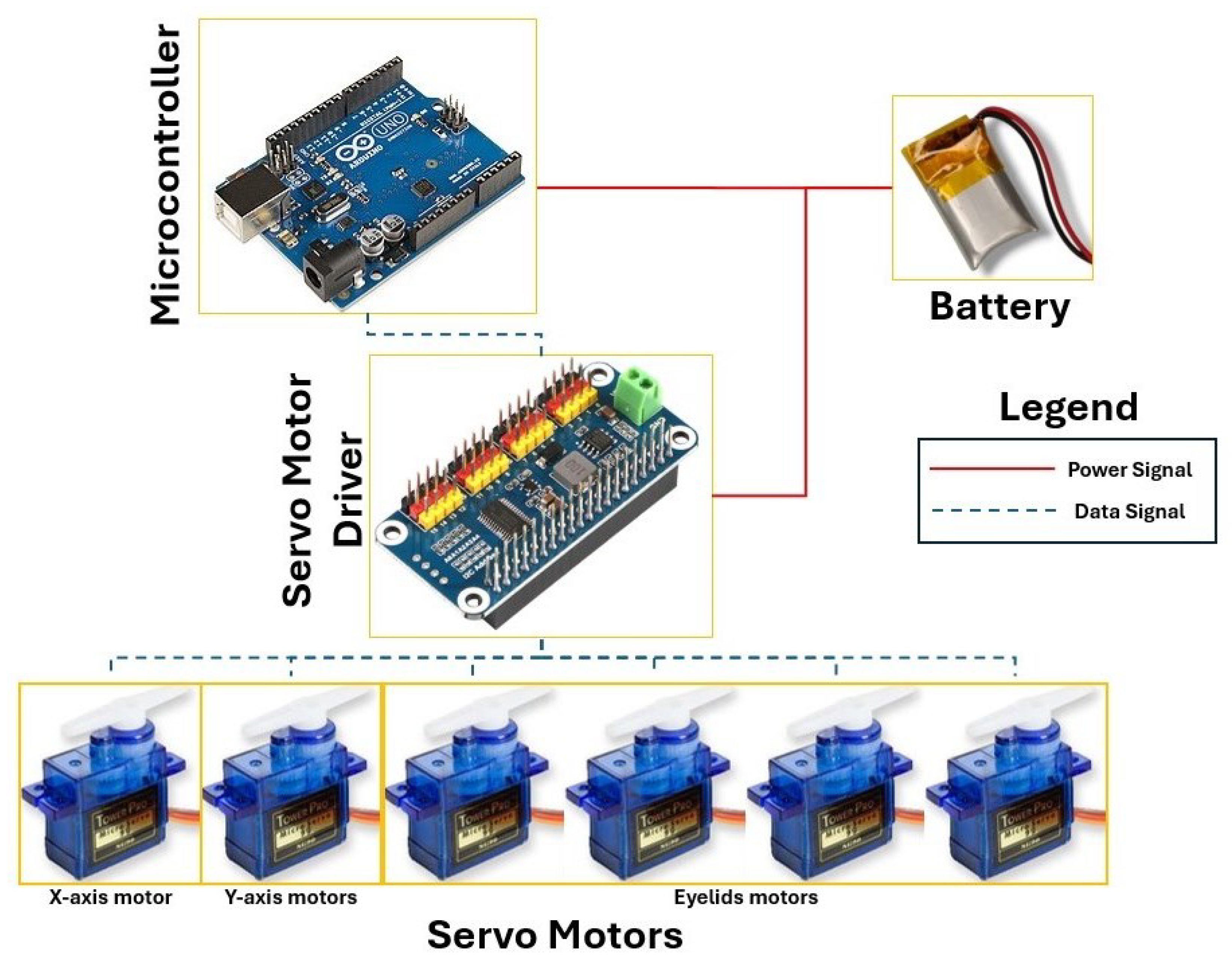
In terms of electrical components, the robotic eye operates through a centralized control system that includes the use of a microcontroller, servo drivers, and a regulated power system. The microcontroller generates the control signals which actuates the eyelid and eyeball movements. It is also connected to the servo driver, which sends the pulse-width modulation (PWM) signals to each individual servo motor that is connected to the servo driver. The power supply system is a 5 V adapter that converts AC to DC output. The control electronics allow for horizontal and vertical eye movement and eyelid actuation to be coordinated to achieve expressive behaviors such as blinking and gazing. More importantly, the system architecture supports the integration of feedback sensors or cameras that can be incorporated in the future, which can provide real-time positional correction or gaze tracking capability. Figure 4 shows the electrical system block diagram. The microcontroller is connected to a power system and interfaced with the servo drivers, which controls the 6 servos for x-axis, y-axis, and eyelid movement.

2.3. Smorphi Robot System Architecture

The Smorphi robot served as the mobile platform for the experiments. It is a modular, reconfigurable, holonomic mobile robot designed for educational and research applications, building upon earlier modular shape-shifting robot concepts developed by the same research group [47,48,49,50] and later formalized as the Smorphi platform [51]. Its main strength lies in its shape-changing capability for different operational needs. As the robot is made up of standardized components that can easily be assembled and disassembled, it makes the platform particularly suitable for prototyping and human–robot interaction research.
In terms of mechanical design, the Smorphi robot is assembled from acrylic plates and aluminum standoffs, and comes in two versions, the Smorphi single version, which is a single robot, and the Smorphi square version, which is a combination of 4 single robots. The Smorphi square version was used for this study; the robot can be rearranged to form seven different shapes. Each module consists of a base layer specifically for locomotion, the middle layers for electronic control and the top layer for sensors or modules to be placed for experimentation of different types of applications, making it an ideal base platform for research studies.
A set of mecanum wheels drives the robot’s locomotion. The wheels are connected to DC motors that can be synchronized for omnidirectional movement. The platform allows for the addition of sensors such as infrared sensors for obstacle avoidance and a Husky camera for applications such as tag and color recognition, allowing for seamless integration without major hardware modifications.
The electrical architecture of the Smorphi robot is based on a distributed control system designed for flexibility, which uses an ESP32-based masterboard and multiple slaveboards that control motors and sensors [52]. The masterboard manages all high-level communication tasks, including wireless connectivity via Wi-Fi and Bluetooth, and executes movement commands received from the host laptop. It transmits information to four slaveboards, with each slaveboard driving the motors of the robot.
The platform supports wired and wireless communications, including UART, I2C, Wi-Fi interfaces and ROS (Robot Operating System) frameworks. Power is supplied through a 12 V battery that can support the system, ensuring that extensions such as the robotic eye module can be connected directly to Smorphi’s power rail.
During the experiments, the robot operated under a hybrid control setup: motion commands were sent from the host computer through a USB serial connection to the ESP32 masterboard, while the robotic eye servos were controlled by a separate Arduino board. This division of control allowed independent yet synchronized operation of the robot’s locomotion and eye actuation. This communication structure also supported teleoperated and semi-autonomous behaviors, which provide the flexibility for different use cases.

2.4. Integration of the 3D Robotic Eyes and Smorphi Robot

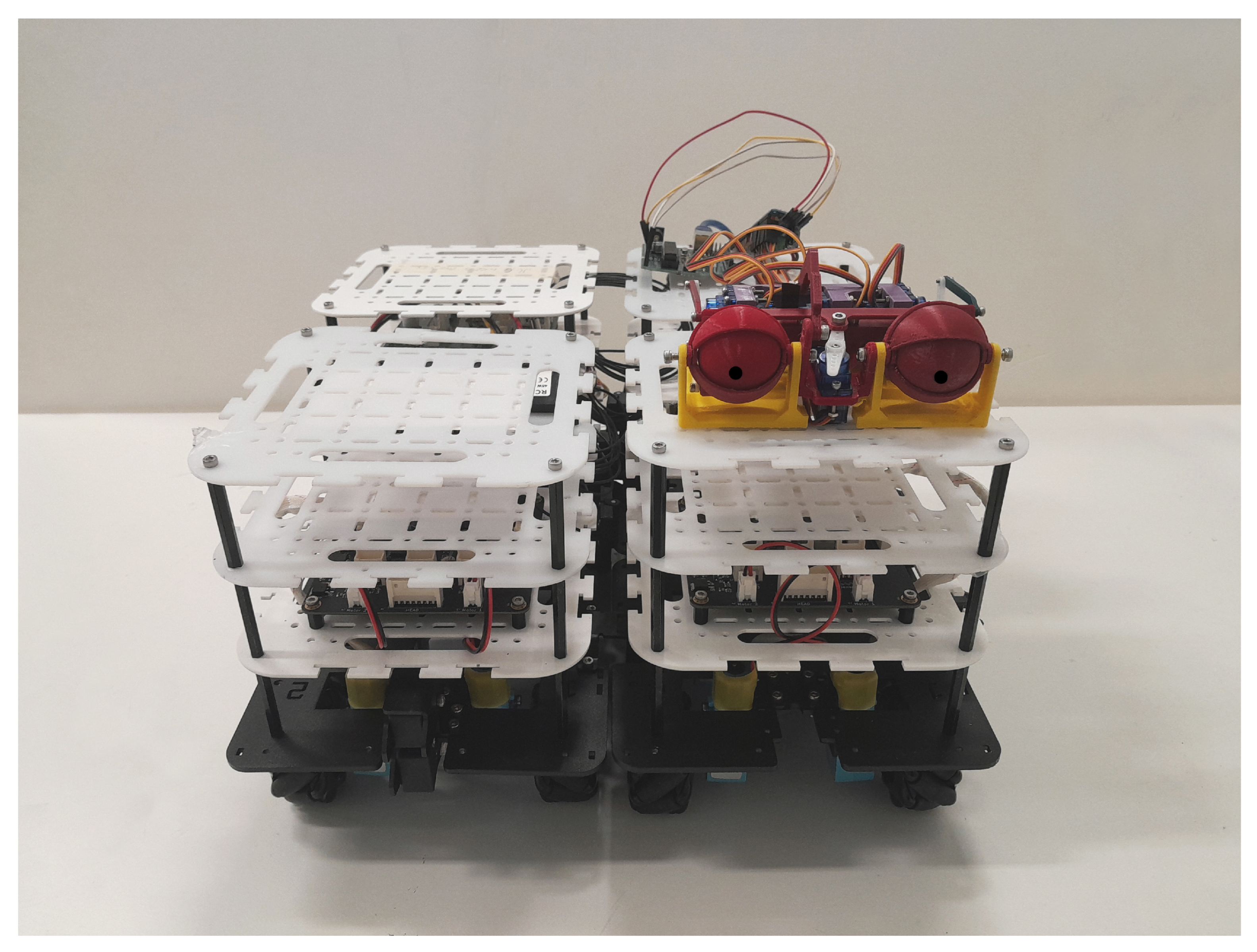
The 3D robotic eye system was mounted directly onto the top acrylic plate of the Smorphi, as shown in Figure 5. The yellow brackets of the 3D robotic eyes were aligned and secured to the pre-existing holes of the acrylic plates using M3 screws. This ensures that the eyes are in a forward-facing orientation and are also less prone to vibrations. The aluminum standoffs of the Smorphi robot allowed for the 3D robotic eye system to be in an elevated position.
The electrical integration between the Smorphi robot’s masterboard and the 3D robotic eye’s microcontroller is through a laptop and communicates via the I2C protocol. This allows for the laptop to process and synchronize eye movements directly with Smorphi’s locomotion, reflecting lifelike behaviors. The protocol enables real-time responsive eye movements and blinking that can be coordinated based on environmental cues, which is the dynamic visual feedback from the webcam in this case. The servos in the 3D robotic eyes draw power from the 5 V AC to DC power adapter, while the Smorphi draws power from a 12 V battery.

3. Experiment Materials and Methods

To validate the proposed system, an experimentation environment was established to evaluate the eye tracking performance of the system at different proxemic distances. This section describes the tracking system developed, the experimental scenarios, and the data collection methods employed.

3.1. Experimental Scenarios and Protocols

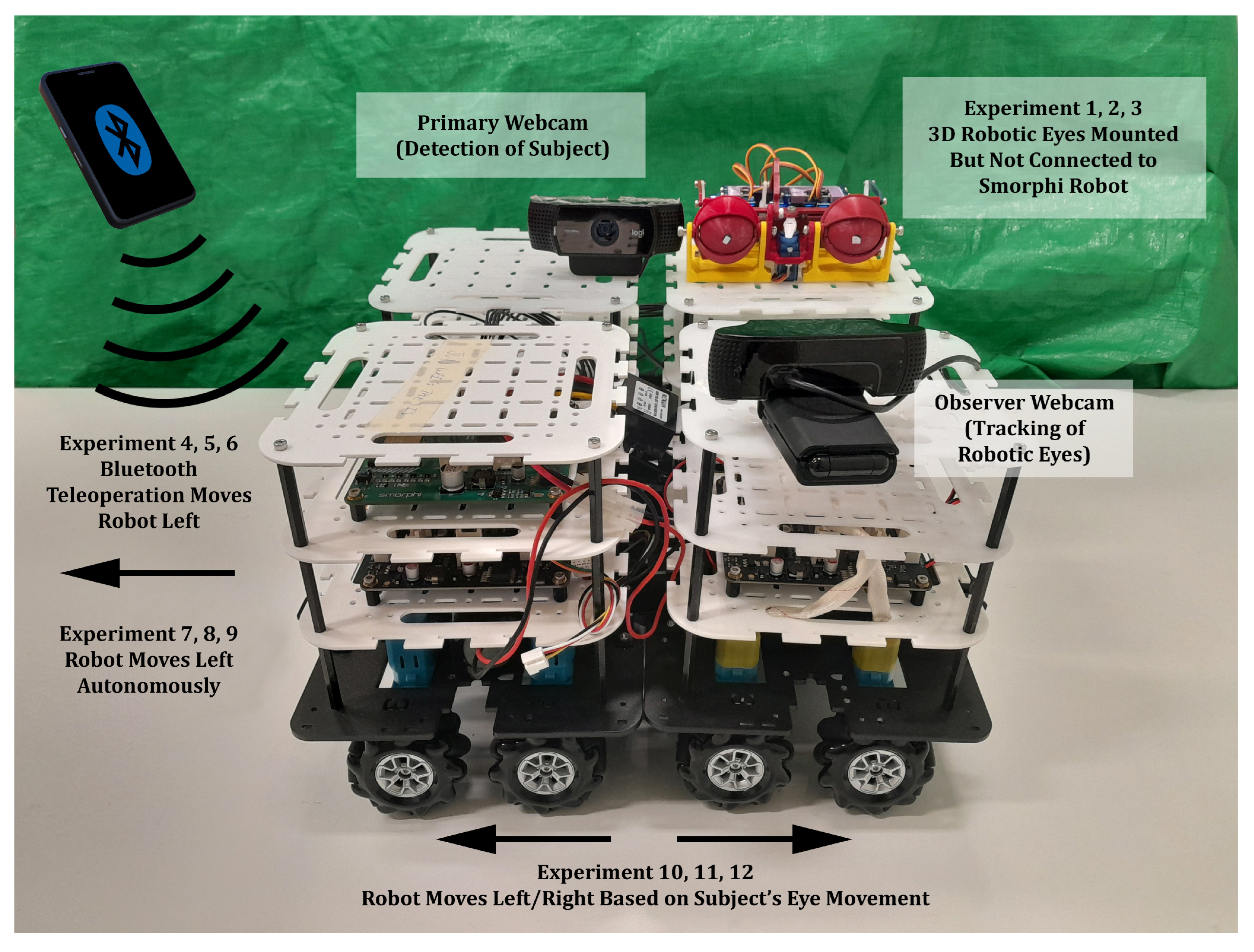
The proposed system has been validated with a total of nine experiments, each with five repeated trials. The 3D robotic eyes and Smorphi robot are shown in Figure 6. For Experiments 1, 2, and 3, the 3D robotic eyes were mounted but not connected to the Smorphi robot. The robot was stationary. The main focus was on assessing gaze mirroring synchrony at three proxemic distances, intimate (<0.5 m), personal (0.5–1.2 m), and social (1.2–3.5 m), respectively. The subject performed a lateral eye oscillation task which lasted approximately 2000 ms, estimated empirically from the response time plots. During the task, the subject moved his eyes side-to-side within the camera’s field of view, which generated a wide spectrum of input values for the servo motors, allowing the eye tracking and motor control pipeline to be exercised across its operational range. The task was not intended as a validation measure, but rather to provide a broad range of inputs for the system. For Experiments 4, 5, and 6, although the 3D robotic eyes were mounted onto the Smorphi robot, there was no integration and the communication loops were separate. The Smorphi robot was teleoperated to move left. The main focus was to evaluate gaze stabilization while the Smorphi robot was moving by teleoperation at the same three distances (intimate/personal/social). The human subject remained stationary at the target distances while the Smorphi robot moved in the left direction, with each cycle lasting approximately 1600 ms. For Experiments 7, 8, and 9, the setup was similar to that of Experiments 4, 5, and 6, but was under autonomous movement conditions to eliminate operator-dependent variability. Experiments 10, 11, and 12 tested the integrated eye-–robot coordination at the same three distances. However, in this case, when the subject’s eyes moved left, the gaze detected by the webcam would drive the Smorphi robot to move left, and when the subject’s eyes moved right, the robot would move right. A full left to right to left oscillation cycle lasted approximately 7000 ms. These scenarios were chosen to progressively stress the vision, communication, and actuation subsystems and to mimic practical classroom dynamics where both eye and body motion must be coordinated [30].
Figure 7 shows the experimental setup where the subject was seated within three proxemic zones from the robot. Tests were conducted in an indoor lab with good lighting conditions and minimal reflective surfaces to simulate that of a classroom environment [53]. Lighting conditions were kept consistent within the experimental environment, and no deliberate changes to illumination were introduced across distances. This is in line with prior research and recommendations for webcam-based vision experiments [54,55]. Each experiment had to be calibrated, the camera framing had to be verified, and a simple calibration script recorded empirical min/max eyeball positions from the video feed.
As distance varied across proxemic zones, the technical factors also naturally varied, especially the effective pixel resolution of the participant’s face within the frame of the camera as well as variations in mechanical loading, such as servo actuation dynamics, friction, inertia etc. These effects are nonetheless, inherent to real-world gaze tracking systems, where changes in distance would also simultaneously affect all these corresponding factors. However, rather than isolating these variables, the present study treated them as integral components of the system pipeline. This is an approach that reflects realistic operating conditions and allows the measured response times to capture the combined influence of sensing, processing, communication, and actuation altogether. While component-level ablation may be valuable for optimization, where the effects of each component is isolated, this study prioritizes system-level behavior and is aligned to the prior literature [10,11,13] where the integrated perception-to-action gaze timings were measured.
The system architecture was configured differently across the three experimental groups to progressively test integration complexity. In Experiments 1, 2, and 3, the communication loop was isolated to the 3D robotic eye system, with no interaction between the eye tracking mechanism and the Smorphi robot. The 3D robotic eye system performed gaze mirroring where the robotic eyes moved in accordance with the subject’s eye coordinates. In Experiments 4, 5, and 6, the Smorphi robot was introduced, but was not integrated with the 3D robotic eyes, and their systems remained separate. During the experiments, the 3D robotic eyes performed the gaze mirroring task, while the Smorphi robot was driven from right to left. It was teleoperated via a Bluetooth device, with user input commands transmitted through C++ code uploaded onto the ESP32-based masterboard. The masterboard communicated the commands to the slaveboards, where the input data were converted into motor encoder ticks, which drive the wheels of the robot, allowing for the robot to move.
For Experiments 4, 5 and 6, the robot was teleoperated to move at an approximate velocity of 0.1 m/s. The focus of these experiments was to assess gaze mirroring under realistic dynamic conditions which reflects practical deployment scenarios. Nonetheless, teleoperation inherently introduces operator-dependent variability with minor variations in velocity. Thus, to isolate the influence of movement velocity, Experiments 7, 8 and 9 were conducted autonomously. The robot was programmed to move at a constant velocity of 0.1 m/s, which matches the velocity under the teleoperated conditions.
In Experiments 10, 11 and 12, the 3D robotic eye assembly and the Smorphi robot were fully integrated and were a gaze-driven control system. The Python script (Version 3.12.7) processed the subject’s gaze data and sent movement instructions to the Smorphi robot via I2C. The Smorphi robot’s left and right movement was based on the coordinates of the subject’s eye positions, allowing the robot to be guided based on eye motion. At the same time, the 3D robotic eyes continued to perform its gaze mirroring task. This integration created a closed-loop interaction between vision, computation, and actuation, performing behavior that visually mirrored the human subject’s gaze in real time.

3.2. The Eye Tracking System

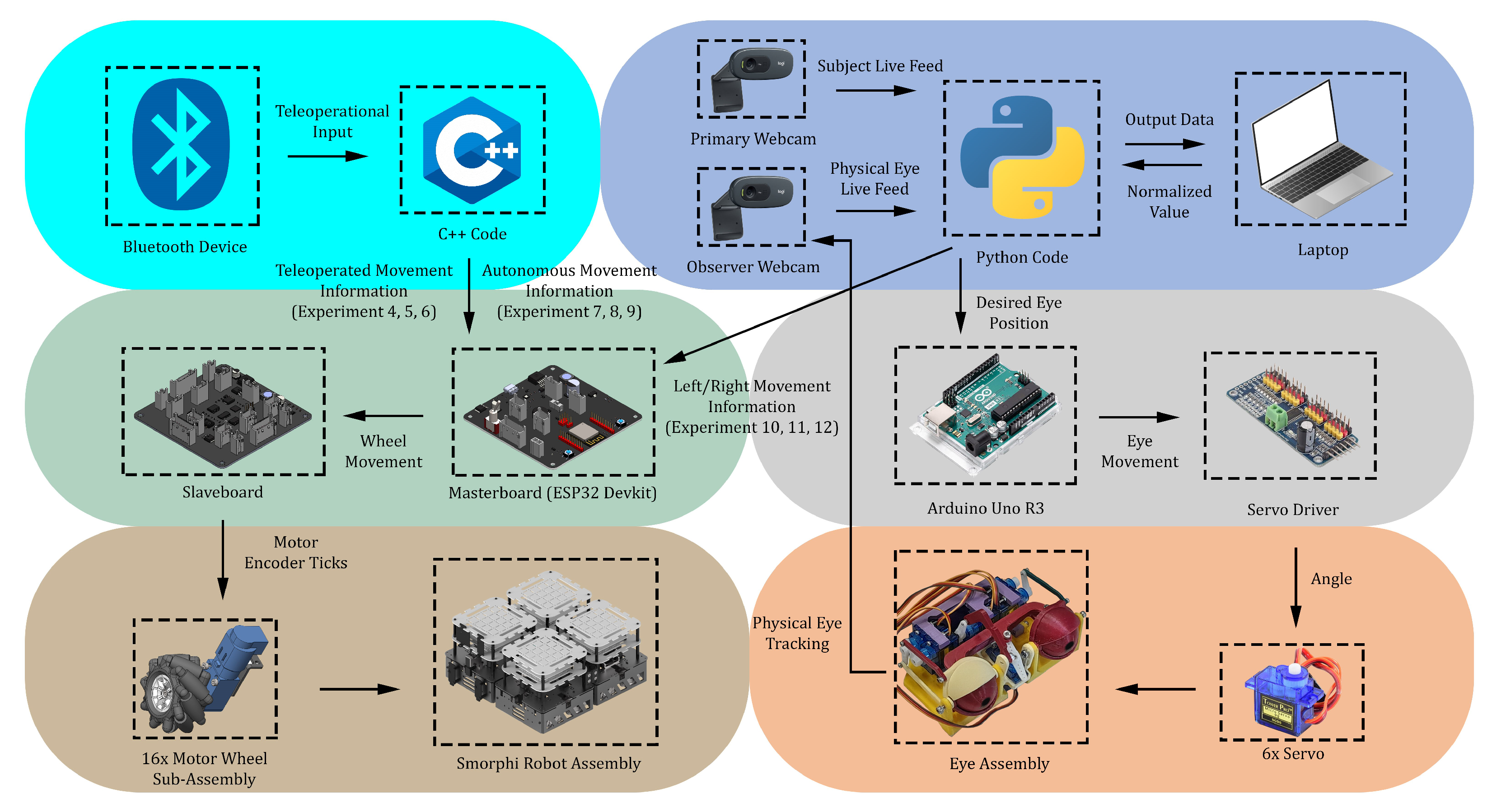
The communication loop of the integrated eye tracking system is shown in Figure 8. Two Logitech C922 webcams record live video at a frame rate of 30 frames per second and transmit the live feed data to a laptop with an Intel Core i7 processor and 8 GB RAM. The visual sampling rate was limited to 30 fps to match the mechanical bandwidth of the servo actuators and serial communication, as preliminary tests have shown that the physical actuation of the servo was the main bottleneck. Therefore, increasing the frame rate was not expected to significantly improve tracking performance. The laptop runs a Python script that uses the MediaPipe landmarking model to process video stream in real time [56], which detects and tracks the subject’s real-time eye positions. The primary webcam is positioned on the subject’s face to capture eye and facial motion data. The observer camera tracks the robotic eye’s movements and provides live feedback on the robot’s response. This allows for the system to visually confirm that the robotic eyes was able to reproduce the subject’s gaze.
This study aims to develop a lightweight gaze tracking system and the approach differs from prior gaze-based control systems that rely on computationally intensive architectures, such as OpenFace 2.0 integrated with industrial UR5 collaborative robots using a MATLAB-based control framework [57]. The Python-based script manages video detection and processing, where each captured frame was analyzed to determine the eye centroid coordinates of the subject and the facial mesh geometry. The horizontal x-coordinates of the detected eye centroids were normalized to a range of 0.0–1.0 to eliminate the issue of having different facial positions or angles across the entire camera frame. This normalization procedure is needed to simplify mapping between detected gaze positions and actuator commands, in line with established practices in the literature that use relative gaze direction over absolute pixel coordinates [11,30].
The normalized eye coordinates of the subject’s eye (NormVal) were transmitted through a serial connection operating at 115,200 baud to an Arduino Uno microcontroller. The Arduino then converts the normalized value into a servo command through a linear mapping function that was constrained by predefined mechanical limits to prevent over-rotation of the 3D-printed eyeball mechanism. The mapping equation is given as follows:
S e r v o V a l = S e r v o m i n + ( S e r v o M a x S e r v o M i n ) × N o r m V a l
The Arduino outputs servo commands via an Adafruit 16-channel PWM driver operating at 60 Hz, which minimizes pulse-width modulation (PWM) jitter and offloads timing from the main microcontroller. Micro-servos were used due to its lightweight nature and compact size. The design intent is consistent with previous studies on lightweight robotic eye systems [58,59]. The 3D-printed robotic eye assembly was securely mounted on the upper deck of the Smorphi robot for all experimentation trials.
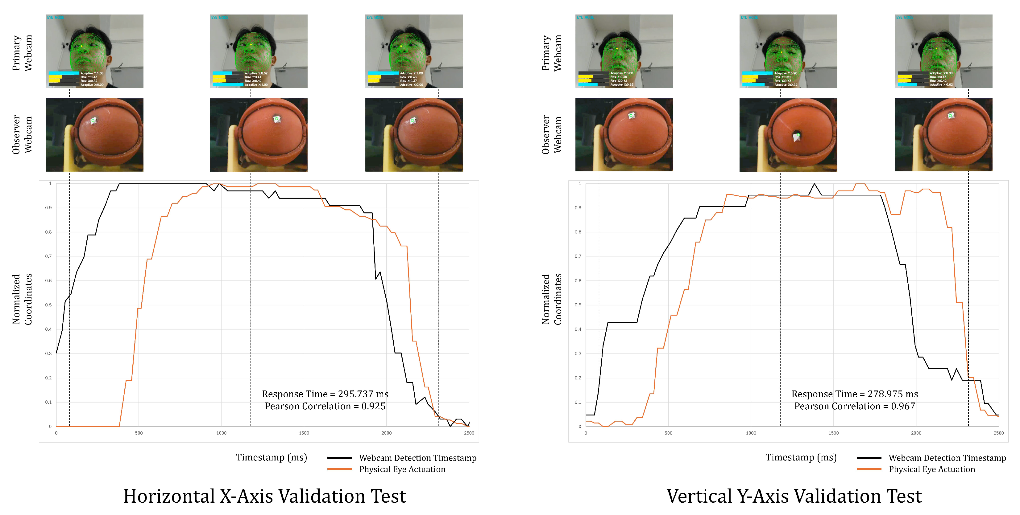
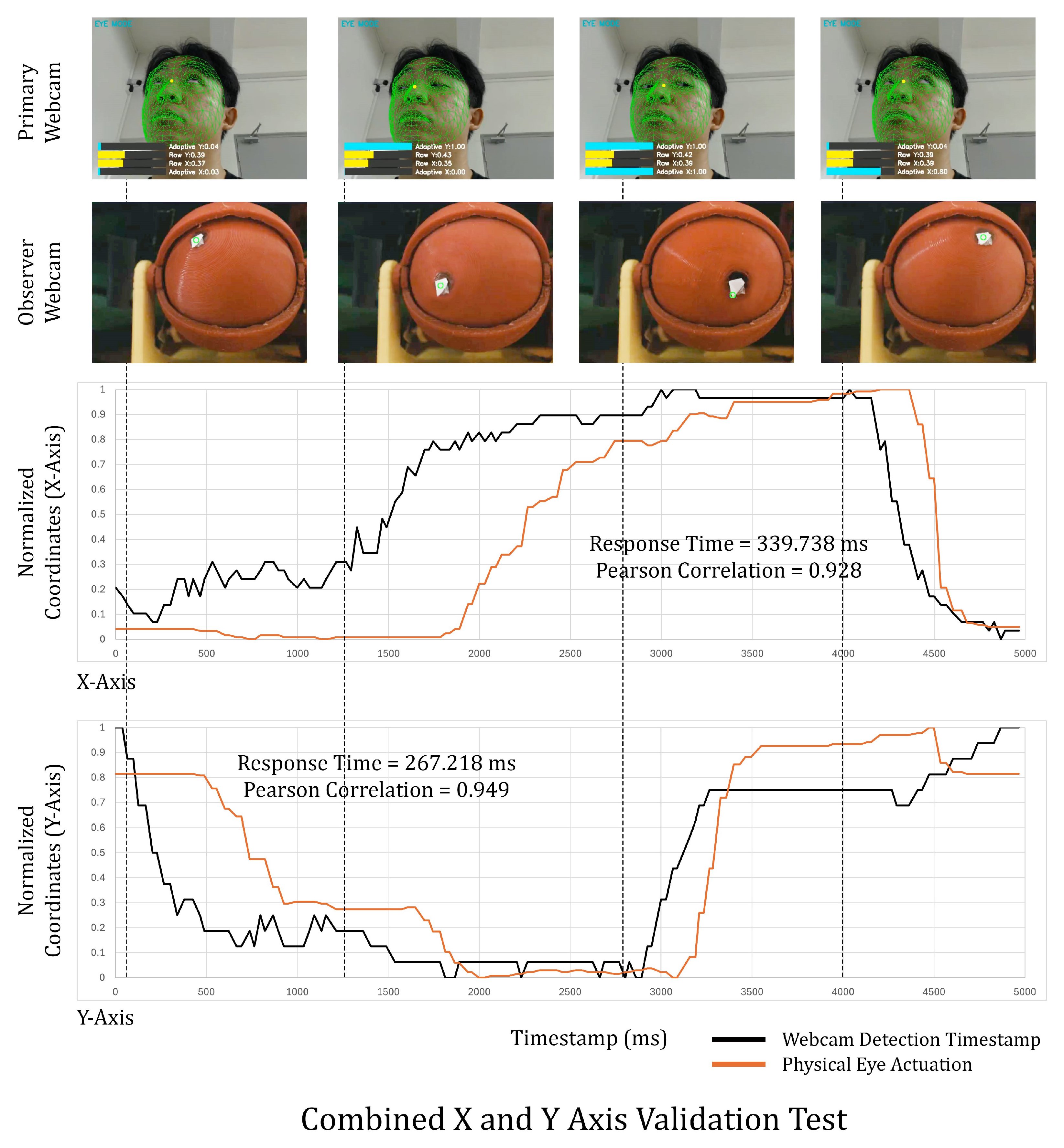
The robotic eye mechanism and tracking pipeline supports two-dimensional gaze control. Validation tests were conducted along the horizontal axis (left-right), vertical axis (up-down), and combined x and y axis.
Figure 9 and Figure 10 show the tracking and actuation signals for each test. The robotic eyes exhibited stable actuation and there was synchronization between detection and actuation, indicating that the system supports two-dimensional gaze control.
Nonetheless, for this study, the movement of the eyeballs was limited to the horizontal (left–right) motion to simplify the experiments, as the main focus was essentially still on the principle of gaze direction replication. Vertical and diagonal gaze behaviors, while technically supported, were intentionally excluded from the primary analysis to ensure experimental consistency across conditions.
A quick calibration procedure was performed prior to the data collection process for each trial. The system was initialized and visually inspected in real time to confirm that eye movement detected by the camera corresponds with the motion range of the robotic eyes. This calibration did not involve the geometric or angular measurement of gaze direction.

3.3. MediaPipe Face Tracking

This study used MediaPipe Face Mesh, an open-source framework by Google, as it has facial landmarking capabilities for real-time facial and iris landmark detection [46]. MediaPipe was also chosen for its low computational overhead and proven performance in low-response time perception tasks, making it suitable for this case. The model generates 468 three-dimensional facial landmarks with high spatial consistency, proving sufficient for the context of this experiment for the real-time estimation of head pose and eye direction [56].
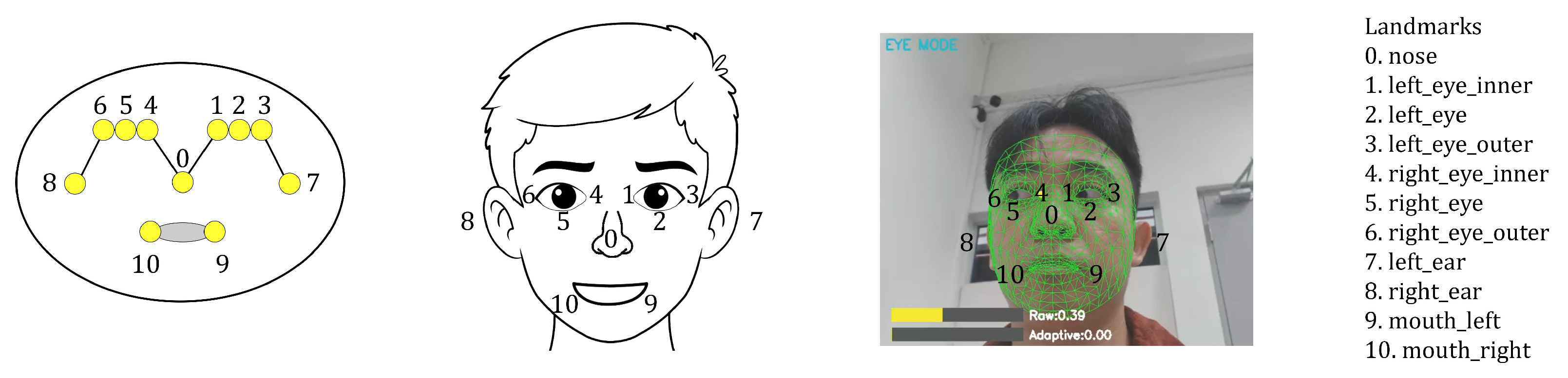
As seen in Figure 11, the system uses MediaPipe Face Mesh for facial landmark tracking and there are three reference images: the base model, schematic representation, and a screenshot from an actual participant during the experiment. For this study, only a few landmarks were used, the nose tip, mouth corners, inner and outer eye corners, and ear reference points, which allowed for a reduced computational load and focus on gaze-relevant features. The nose landmark served as the origin for calculating relative horizontal eye displacement, which was normalized to a 0.0 to 1.0 range, representing the relative horizontal eye position from the leftmost to the rightmost extent. This value was used to generate the servo control value (NormVal) for robotic eye movement.
This study focuses on relative gaze mirroring synchrony rather than estimating absolute human gaze angles. The system does not rely on an external angular ground truth (e.g., gaze direction in degrees or motion capture markers).
The minimum and maximum detected eye positions correspond to the physical limits of the robotic eye mechanism. As such, the expected ground truth is defined as the relative correspondence between the normalized input gaze position and the normalized actuator position.
The primary webcam streamed frames to the MediaPipe pipeline, which returned landmark coordinates (x, y, z). The horizontal offset between the face center and the eye landmarks was mapped to servo commands sent to the Arduino controller, while the secondary observer webcam recorded the robotic eye movement, which is used to validate the response of the eye movements and calculate response time. This allowed for comparison between detected facial movement and the physical actuation of the 3D robotic eyes, in line with previous gaze tracking studies [60].
MediaPipe’s BlazeFace convolutional model allows for operations to be conducted on standard hardware, while maintaining an average response time below 500 ms [46]. The Python script performs a brief calibration to record minimum and maximum eye coordinate bounds for normalization, especially for Experiments 1, 2 and 3 to account for experimental errors such as lighting conditions to ensure landmarking accuracy. The observer-to-camera validation, which is a process of simply moving within the camera frame and observing if the webcam captures the movement, further verified synchronization between detected gaze and robotic eye actuation.

3.4. Data Collection Process

Two webcams were used, with a primary webcam facing the subject and an observer webcam focused on the 3D robotic eyes. The primary webcam detected the participant’s eye position in real time and generated a normalized value (NormVal) which was sent to the microcontroller. Each detection was timestamped in ISO format, while the observer webcam also simultaneously recorded the 3D robotic eyes’ movement, and computed the coordinates (ObsX, ObsY) of the eye markers in each frame.
A white tape marker was affixed to the eye surface to track the motion of the robotic eyes. The Python script tracked the coordinates using a Gaussian-weighted centroid estimation rather than using simple color thresholds. Within the observer webcam frame, the user clicks on the white tape to initialize the script and the pixel RGB values within the region were weighted using a Gaussian method, which suppresses edge noise. The script then tracks this coordinate within the screen. This approach reduced sensitivity to lighting variations and minor pixel-level artifacts, resulting in more stable coordinate estimation across frames.
These coordinates were later normalized to the same 0–1 range as NormVal, allowing direct comparison between commanded and actual eye positions. The Python script logged these parameters into one CSV entry per event command.
All recorded time series were inspected and cleaned prior to analysis. Rows where the face/iris was not detected by the primary webcam or where the observer webcam did not produce a valid centroid were removed. Remaining series were time-aligned using ISO timestamps, where small frame rate differences existed and resampled via nearest-neighbor alignment to the primary webcam timeline. For the observer camera and external video, pixel centroids were normalized to the same 0–1 range as NormVal by applying per-trial min/max normalization derived from the calibration step.
This study measures the detection-to-actuation response time (hereafter referred to simply as ’response time’), which represents the total latency from the moment a human gaze shift is detected to the completion of the robotic eye movement. The response time values were estimated using a temporal alignment approach based on Pearson’s correlation. The normalized gaze command signal and the observed robotic eye position were treated as two time series. Using an Excel function, the observed eye position signal was incrementally shifted forward in time relative to the command signal for each frame offset, where the Pearson’s correlation coefficient, r, was computed between the overlapping portions of the two signals. The offset yielding the maximum correlation was selected as the estimated system response time, corresponding to the temporal delay that best aligned the commanded and observed eye movements.
This analysis approach mirrors prior HRI evaluations where response time decomposition and trajectory alignment are used to quantify tracking synchrony and temporal responsiveness [11,61].
The study did not utilize absolute ground truth measurements to validate the reliability of the system. Instead, it was evaluated via the following: First, the standard deviation of response times was a measure of variance across the trials within each experiment. Second, Pearson’s correlation between the normalized gaze command signal and the observed robotic eye motion was an indication of tracking synchrony. Third, prior to each data collection trial, a functional verification was performed in which the subject gazed left and right to confirm that the robotic eyes responded to user input rather than random noise.
The trials were conducted by the authors for the purpose of evaluation of the technical system. There was no experimentation on human subjects or assessment of interaction outcomes at the perceptual or behavioral level.

4. Results

4.1. Gaze Mirroring Synchrony

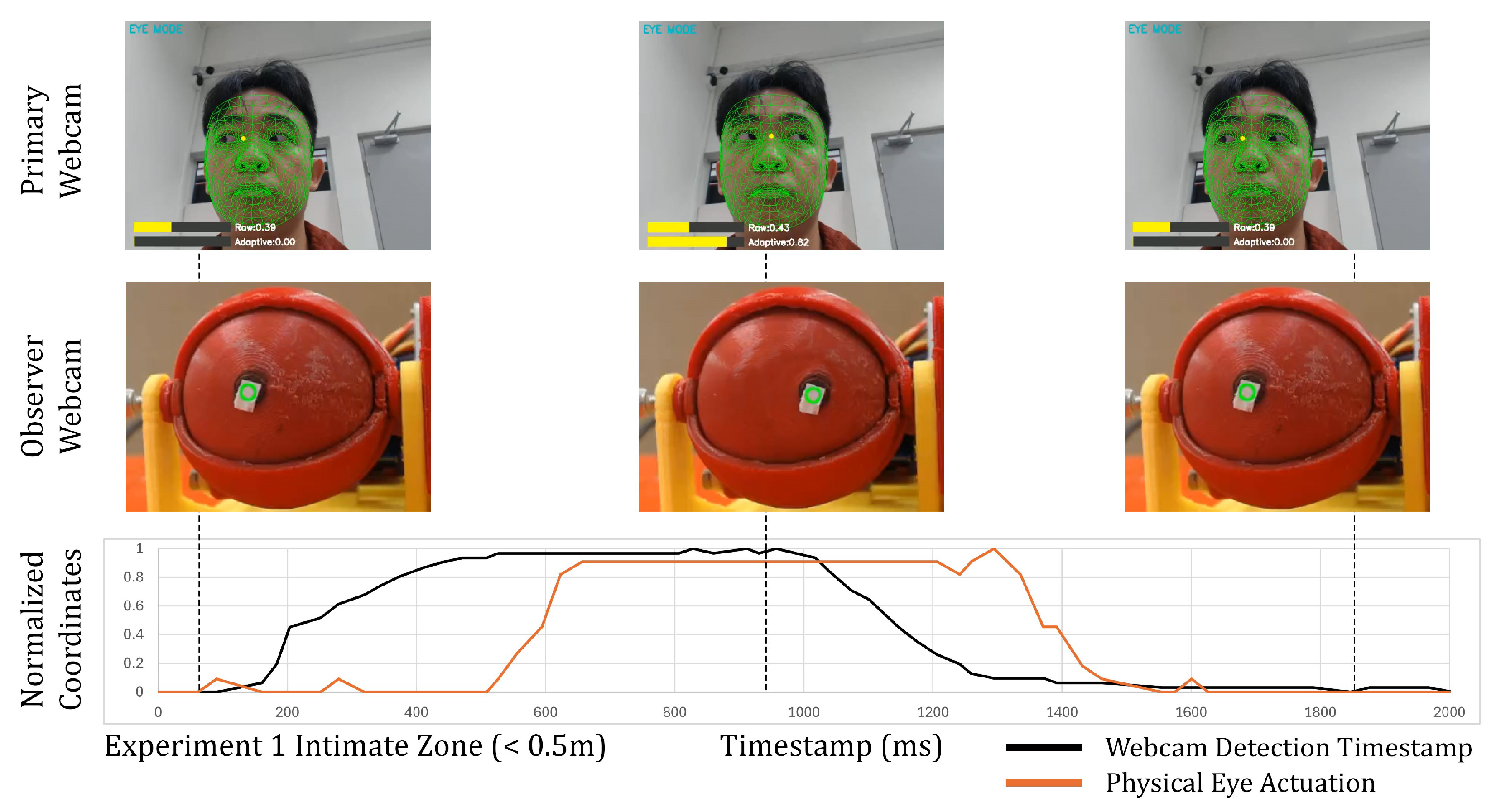
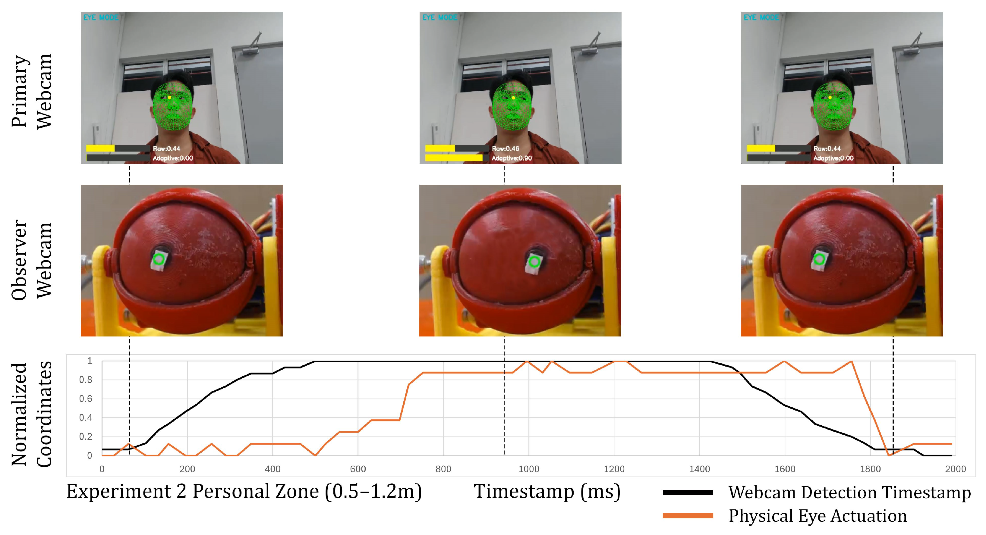
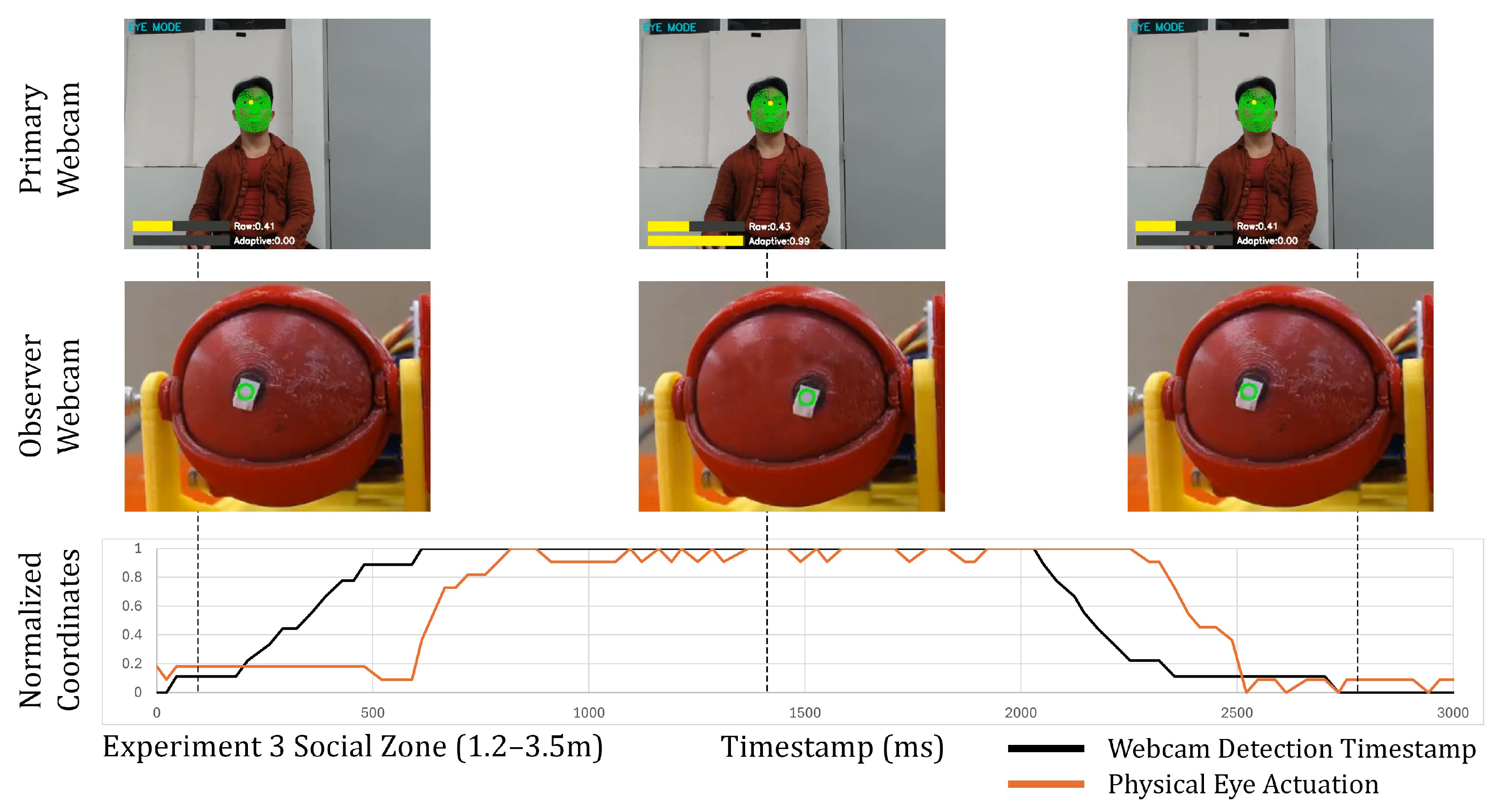
Table 4 shows the static gaze mirroring experimental results of Experiments 1, 2 and 3 across the intimate zone (<0.5 m), personal zone (0.5–1.2 m) and social zone (1.2–3.5 m), respectively. Figure 12, Figure 13 and Figure 14 contain a screen capture of the subject in the primary webcam and the 3D robotic eyes in the observer webcam. In the primary webcam, it also shows a scale of the raw NormVal and the adaptive NormVal. The raw NormVal shows the absolute screen coordinates of the subjects’ eye position. The script takes the minimum and maximum raw NormVal every 10 s cycle and normalizes this range from 0.0 to 1.0. The newly detected screen coordinates of the subjects’ eyes will then be the adaptive NormVal that will be sent to the 3D robotic eyes. The graphs show the normalized horizontal coordinates from the primary webcam detections (black lines) and the corresponding physical eye actuation recorded by the observer webcam (red lines). The difference between the black line and the red line is the response time between detection and actuation, which combined detection time, time taken for serial transmission, and mechanical response time. Visually, the detection and actuation graphs moves up and down in an identical manner. The motion of the subject’s eyes reached the extreme ends and stabilizes for a brief moment before changing directions. Across the three experiments, where the proxemic distances were varied, the overall motion patterns between detection and actuation showed strong alignment, indicating effective translation of visual input into motor response.
The mean response time across Experiments 1, 2 and 3 were 329.5 ms, 283.5 ms and 286.2 ms, with a standard deviation of 23.7 ms, 48.9 ms and 34.1 ms respectively, which indicate a small degree of variance. Pearson’s correlations were high (r = 0.88–0.92), suggesting that the synchronization between the detected eye motion and the corresponding servo actuation was stable. The values were within the range of response times commonly associated with natural reaction speed and the typical human saccadic or gaze reaction time, and based on the literature, would be perceived as socially contingent behavior, as seen in Table 4.
Experiment 2 and Experiment 3 achieved low response times of 283.5 ms and 286.2 ms, respectively, suggesting that there might be an optimal detection range of distance for the webcam. Experiment 1 yielded a slightly higher response time of 329.5 ms, which may reflect the differences of tracking at closer distances, where facial features occupy a larger portion of the frame.

4.2. Gaze Stabilization (Teleoperated Movement)

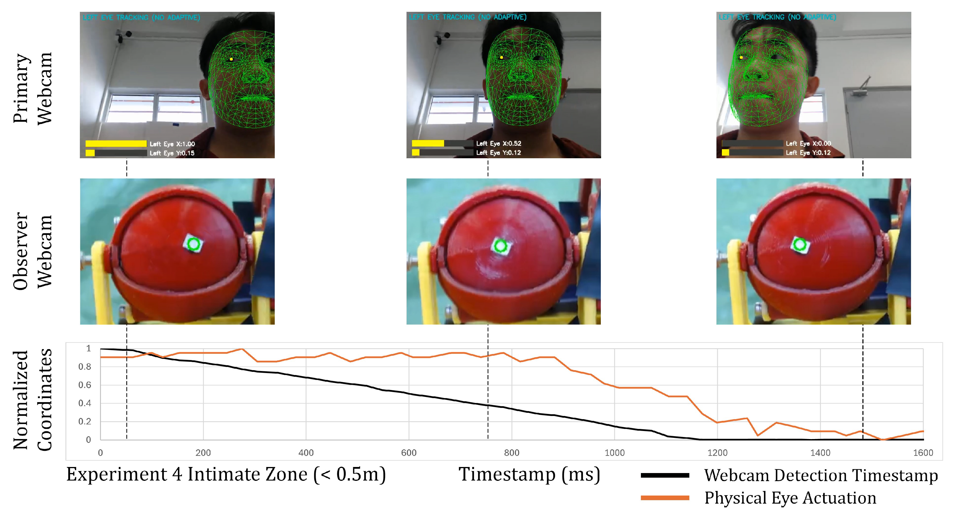
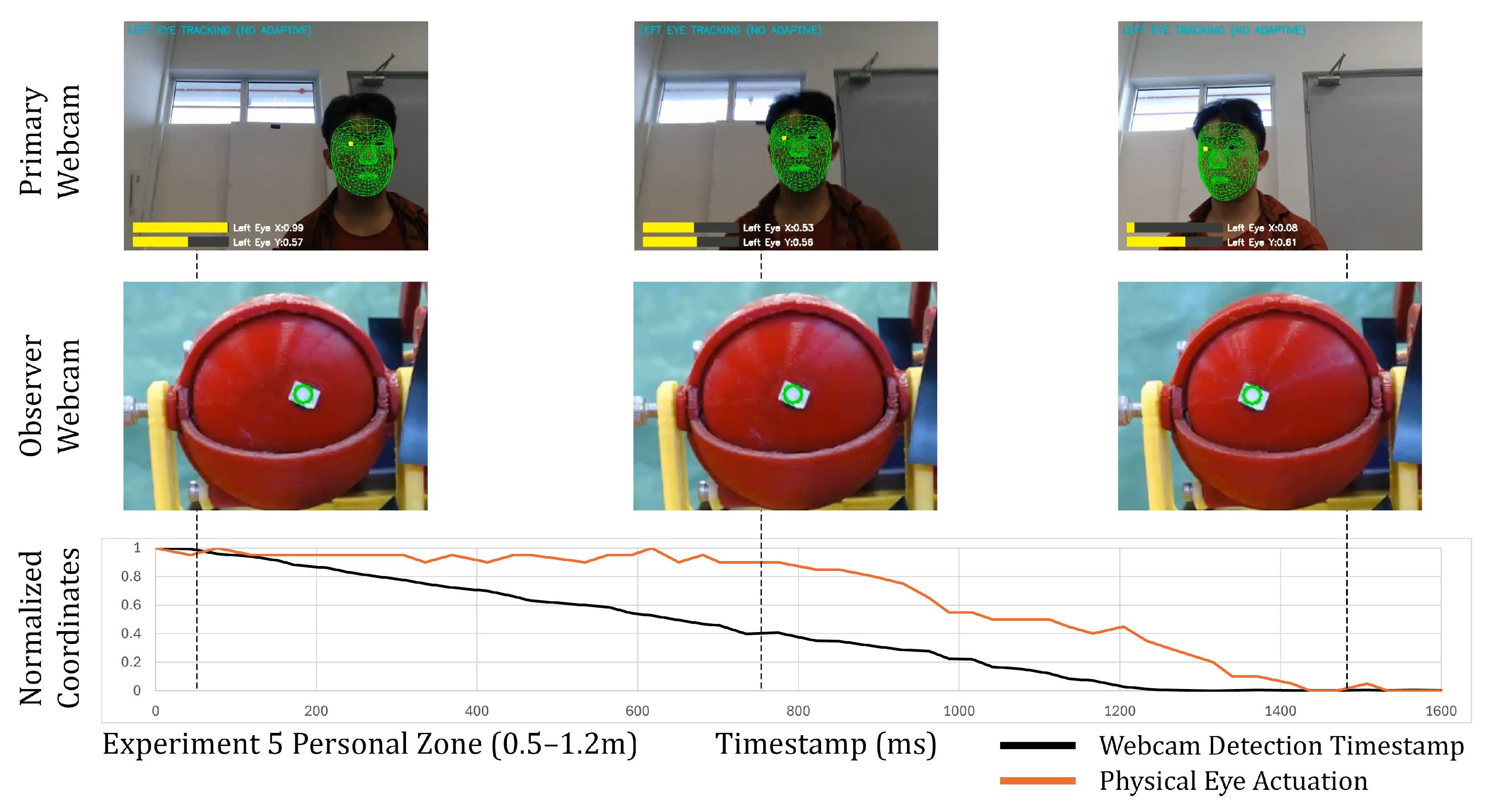
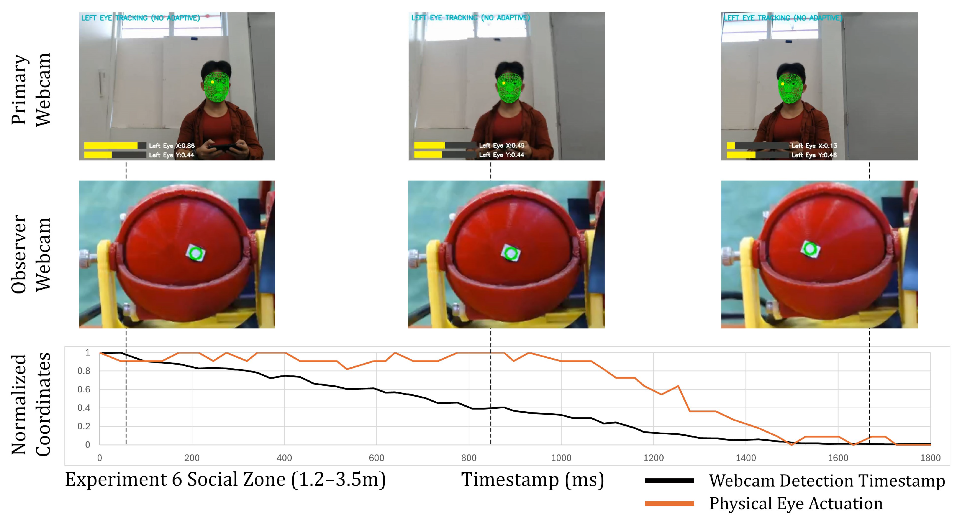
The results for Experiments 4, 5 and 6 are shown in Table 5 and the corresponding graphs are seen in Figure 15, Figure 16 and Figure 17 respectively, where we examined the performance of the gaze mirroring system when the Smorphi robot was in motion under teleoperation, while the human subject remained stationary. The primary objective was to assess how robot movement and platform vibrations affected the synchronization between webcam-detected gaze and the physical 3D robotic eye response. The Python script uses the subjects’ left eye x-coordinate to simplify the detection process. As the robot moved from right to left, the subject appears to move from right to left in the primary webcam’s frame. In response, the 3D robotic eyes will also orient the gaze in the direction of the subject.
The Pearson correlations for Experiments 4, 5 and 6 remained consistently high (r = 0.95–0.98), as seen in Table 5, indicating that the gaze system maintained reliable tracking despite robot motion. The mean response times are higher compared to the static experiments, with mean values of 509.7 ms, 591.2 ms and 963.6 ms for Experiments 4, 5 and 6 respectively. These higher values reflect the cumulative effect of added motion-induced vibration. The response times for Experiments 4 and 5 were close to the 500 ms benchmark for attentive and intentional behavior. The response time of Experiment 6 of 963.6 ms was associated with the benchmark for collaborative interaction and for the behavior to be perceived as intentional but is close to the upper limit for natural gaze.

4.3. Gaze Stabilization (Autonomous Movement)

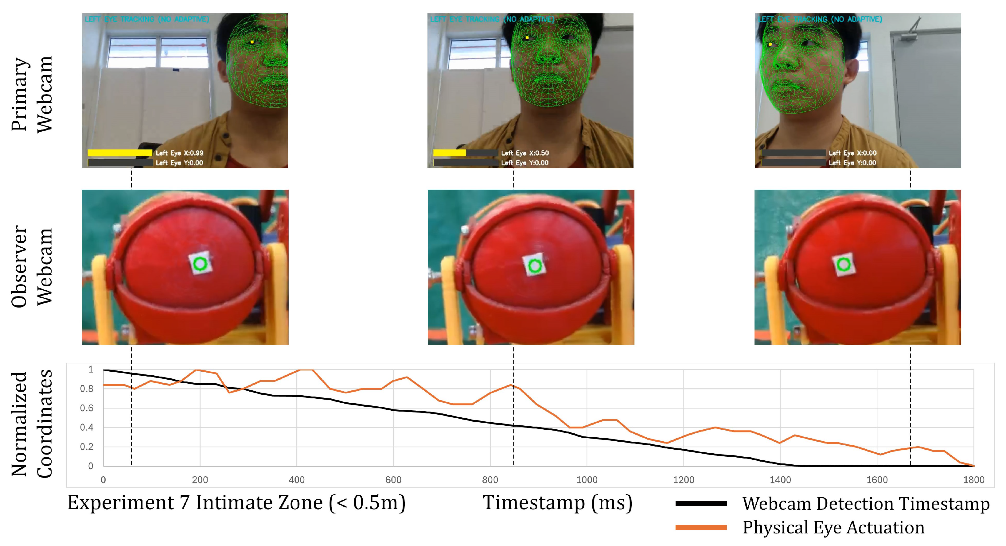
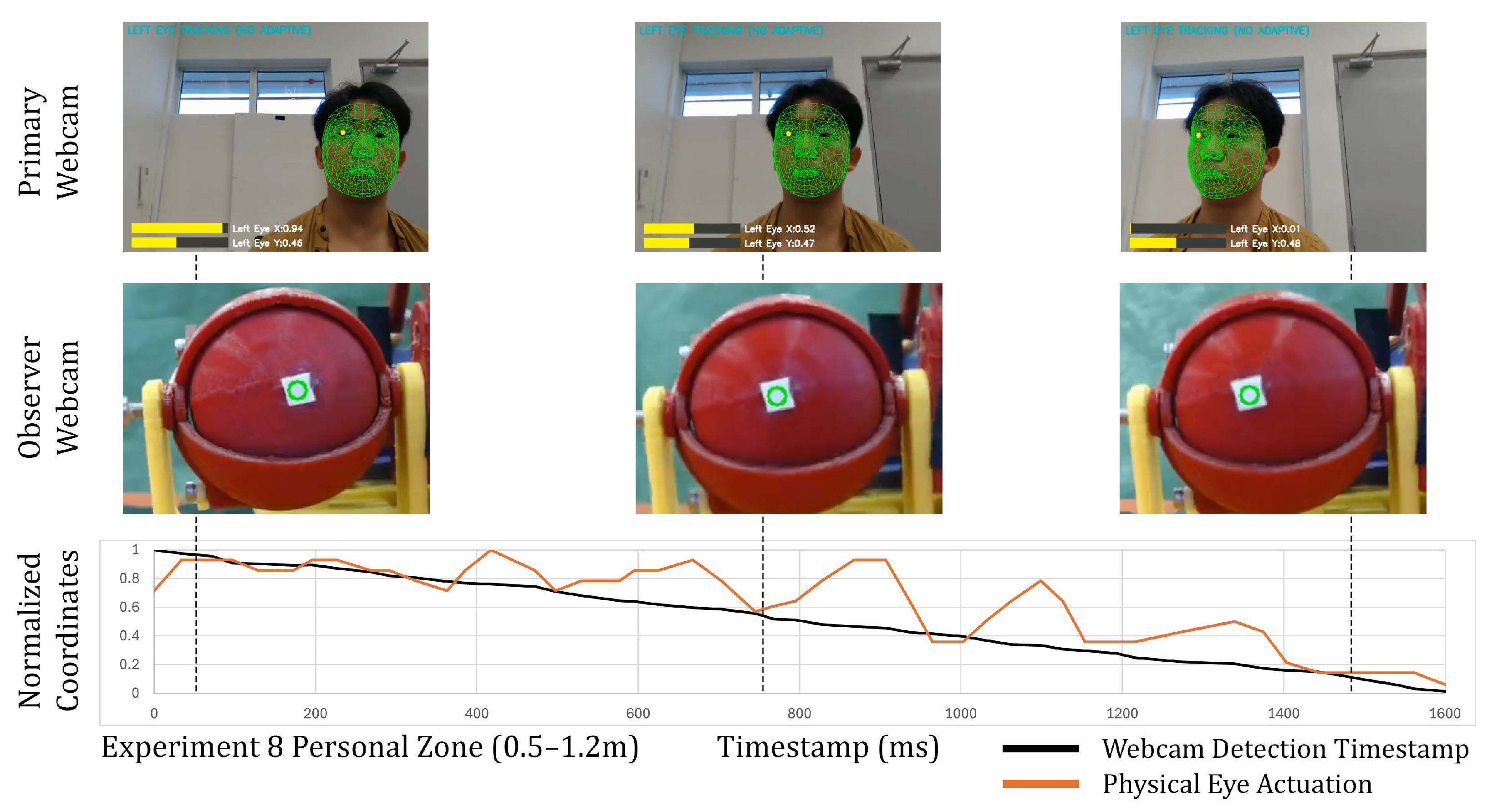
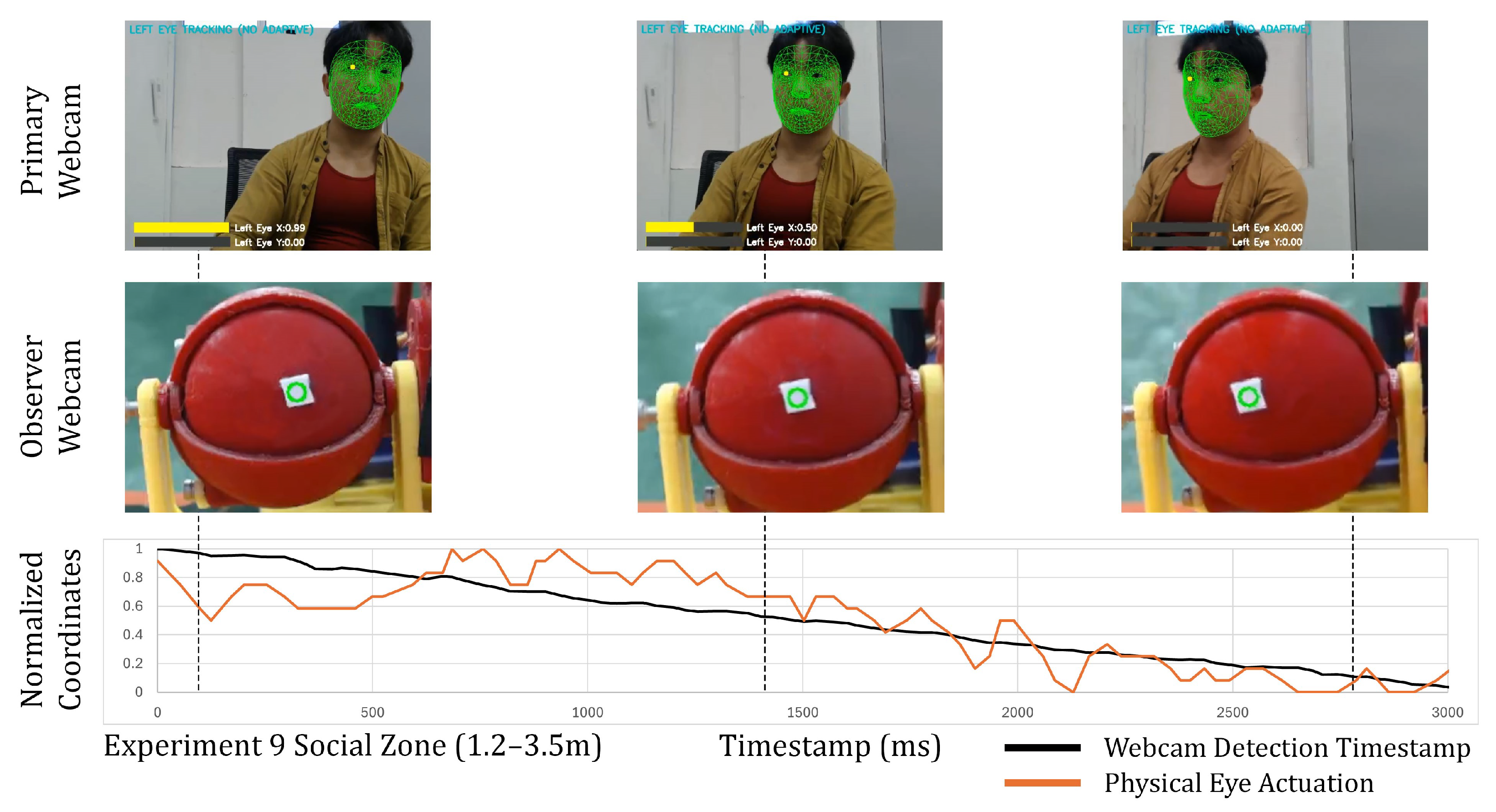
The results for Experiments 7, 8 and 9 are seen in Table 6 and the graphs for the autonomous movement tests are seen in Figure 18, Figure 19 and Figure 20 respectively. The main objective of this was to assess how the autonomous robot movement compared to teleoperated conditions. The setup was the same as the conditions in the teleoperated experiments, but the robot moved from right to left at a predefined constant velocity of 0.1 m/s which removes human operator skill as a variable.
The Pearson’s correlations for Experiments 7, 8 and 9 remained consistently high (r = 0.93–0.96), as seen in Table 6, indicating that detection and actuation of the robotic eyes maintained synchronization despite robot motion. The mean response times were lower compared to the teleoperated experiments, with mean values of 356.7 ms, 369.7 ms and 668.4 ms for Experiments 7, 8 and 9 respectively. The lower values show that human operator skill has an influence on the response times with variations in operator input inherent to manual control. The autonomous conditions improved consistency and reduced variance in response times (SD = 28.9–135.5) compared to teleoperated conditions (SD = 117.0–260.0). The response times for Experiments 7, 8 and 9 were close to the 500 ms benchmark for attentive and intentional behavior.

4.4. Integrated Coordination

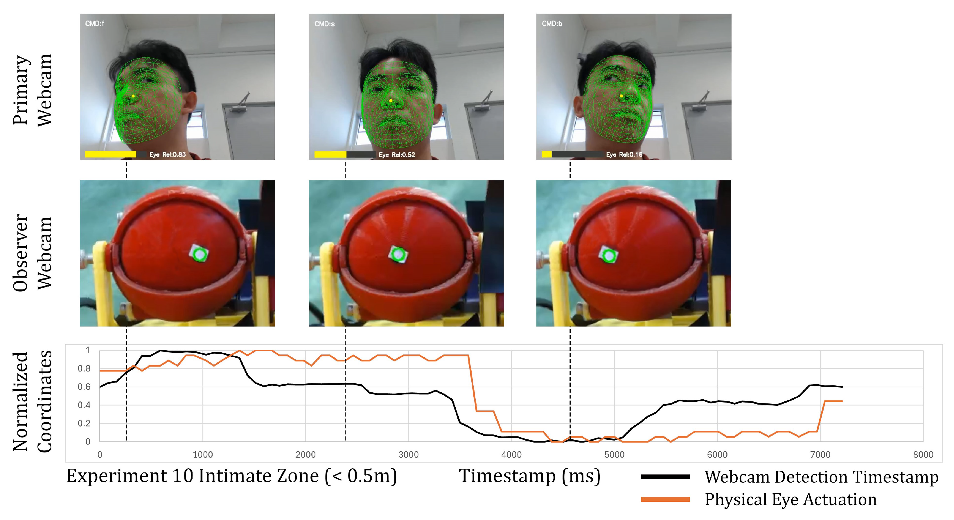
Experiments 10, 11, and 12 evaluated the system under full integration, where both the 3D robotic eyes and the Smorphi robot moved simultaneously in response to the participant’s gaze. The Smorphi robot was given a command to move left, right or stop based on the detected NormVal. For a NormVal less than 0.35, the robot will be given a command to move left. If it falls within 0.35 and 0.65, it will stop. If the value is above 0.65, the robot will be commanded to move right. Concurrently, the 3D robotic eyes rotated the eyeball position to mirror the gaze of the subject, while the observer webcam captured the coordinates of the 3D robotic eyes. The normalized coordinates were plotted to determine the response time between detection and actuation.
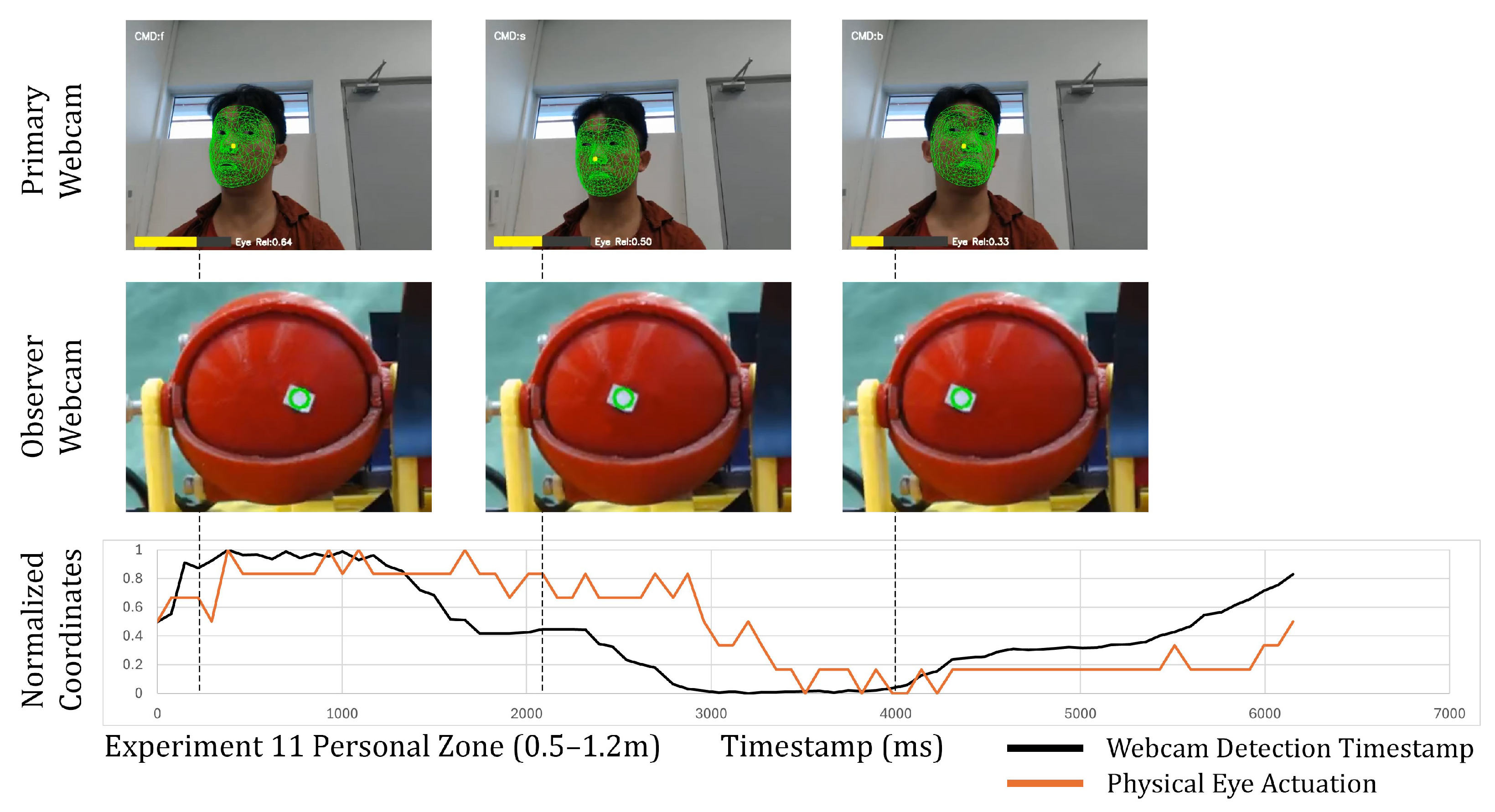
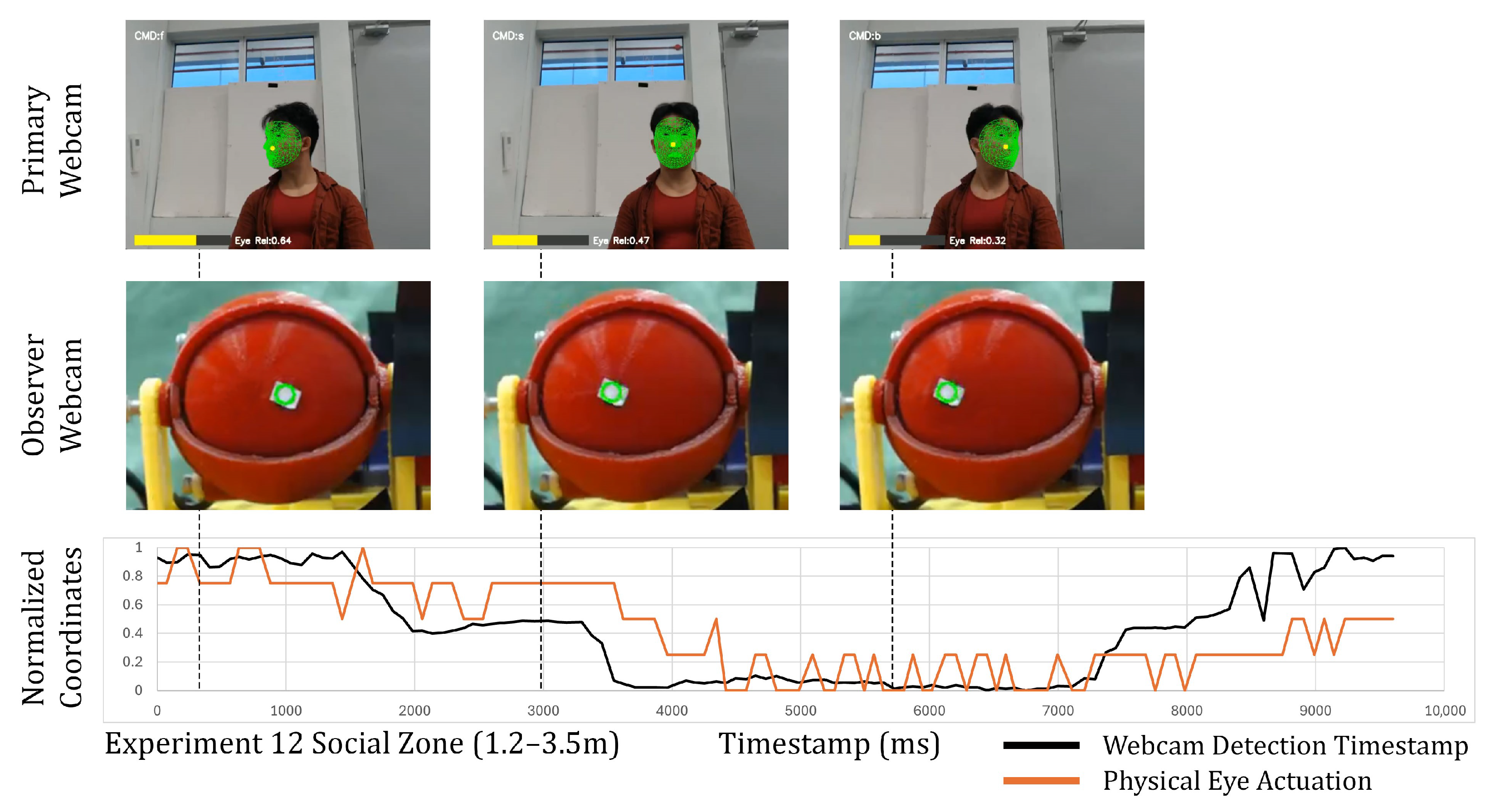
The results of Experiments 10, 11 and 12 are shown in Table 7 and the corresponding graphs are seen in Figure 21, Figure 22 and Figure 23 respectively. The Python script calculated the ratio of eye centerpoint coordinates to face coordinates. At increased distances, lateral eye movements alone produced a small range of values and the subject had to tilt their face left/right to exaggerate the ratio and send a greater range of values to the 3D robotic eyes which was the most apparent in Experiment 12, Figure 21. Throughout the experiments, the corresponding commands sent to the robot based on NormVal were observed to be accurate.
The graphs show a clear increase in overall response time, in Figure 21, Figure 22 and Figure 23, averaging 568.8 ms for Experiment 10, 817.8 ms for Experiment 11, and 1175.9 ms for Experiment 12 in Table 7. For Experiment 10, the response time was aligned with timings associated with attentive and intentional gaze behavior. The response time in Experiment 11 and Experiment 12 would be perceived to be intentional and close to the upper limit for natural gaze behavior.
The Pearson correlations (r = 0.82–0.90) in Table 7 indicated that there was a moderate-to-strong correlation, which implies synchronization between the subject’s eye movements and the 3D robotic eye’s movement. The tracking trajectories remained generally smooth for Experiments 10 and 11 as seen in Figure 14 and Figure 17 respectively.
Overall, the three experiments successfully validated the integration of the system, which incorporated gaze mirroring and robot movement based on the subject’s gaze direction. This demonstrates the feasibility and capabilities of gaze-driven robot control.

5. Discussion

The results from the experiments demonstrated that human-to-robot gaze mirroring is achievable with response times ranging from 283 ms and 1176 ms across various proxemic distances and under different conditions. The existing literature shows that these response times would be perceived differently by users based on response time benchmarks. In the static experiments (Experiments 1, 2, and 3), response times ranged from 283.5 to 329.5 ms, which was associated with a natural reaction speed and socially contingent behavior, as seen in Table 4.
While the static experiments achieved response times that are within the natural gaze benchmarks, the deployment in educational and therapeutic settings would require the robot to be in motion and thus require more computational load. Hence, further experiments were conducted to evaluate the responsiveness of the system while the robot was under teleoperated movement and fully integrated conditions.
The teleoperated movement trials (Experiments 4, 5, and 6) showed that robot locomotion caused an increase in response time. The response times as seen in Table 5 for Experiment 4 and Experiment 5 were 509.7 ms and 591.2 ms. According to the literature, these response times are perceived as attentive and intentional gaze behavior. The response time for Experiment 6 was 963.6 ms and based on existing studies, the gaze behavior is perceived to be intentional but close to the upper limit for natural gaze. This set of experiments is in line with expectations. The increased computational load and vibrations during teleoperation motion increased response times and also had a slight reduction in tracking synchrony compared to the static conditions, which shows how operational dynamics affect system performance.
The autonomous movement experiments (Experiments 7, 8, and 9) with response times of 356.7 ms, 369.7 ms and 668.4 ms were close to the 500 ms benchmark for attentive and intentional behavior. Compared to the teleoperated conditions, it showed that removing human operator input and the constant velocity of the robot led to lower response times. At the same time, in comparison to the static conditions, the observed increases in response time were due to robot motion and vibrations.
In the integrated eye–robot coordination experiments (Experiments 10, 11, and 12), the combined control loop saw a greater increase in response times. As seen in Table 7, Experiment 7 had a response time of 568.8 ms which would be categorized as attentive and intentional behavior. Experiments 11 and 12 had response times of 817.8 ms and 1175.9 ms respectively, and based on the literature, are still perceived to be intentional but fell close to the upper limit of natural gaze behavior. Experiment 12 had a standard deviation of 577.4 ms which could indicate a less consistent performance, but overall, the Pearson’s correlations (r = 0.82–0.90) demonstrate that the robot’s gaze mirroring function based on the subjects’ eye position was synchronized.
Existing robotic gaze systems, particularly iCub-based platforms, have gaze response times of 200–500 ms for simple gaze tasks and 500–1000 ms for more complex intentional actions in gaze behavior tasks [10,11,18,62]. In comparison, the proposed system has a response time of 280–330 ms under static conditions, which is on par with the lower end of existing gaze systems. Under teleoperated, autonomous and integrated movement conditions, the response times generally increase but remain within established perceptual benchmarks in comparison to existing gaze systems.
The higher response times of Experiments 6 and 12 could be due to the fact that the components were 3D printed and thus, surface inconsistencies introduced mechanical friction within the eye sockets. As a result, a variable minimum force was required to initiate rotation, increasing the mean response time and variance between trials. Furthermore, as Experiments 6 and 9 were conducted at a further distance, the robotic eyes had a smaller actuation range, making it harder to consistently overcome static friction. Nonetheless, once the initial resistance was overcome, the robotic eyes were found to be synchronized, indicating stable behavior after motion onset. Other factors that contribute to the increase in response time and standard deviation include reduced facial landmark precision at greater distances [63], lower landmark tracking confidence [54], and robot vibrations during motion.
The response time benchmarks, which were taken from the prior literature, were cited within this study and are used solely as interpretive references to give context to the measured response times rather than to make claims of equivalence between human–human and human–robot interaction.
As human movement input naturally introduced variability, one of the challenges faced during the experiments was to ensure the consistency of how the tasks were executed across multiple trials. This was mitigated through the use of normalized coordinates and tracking using a white-tape marker, which stabilized the data representation and minimized sensitivity to lighting.
Overall, the Pearson’s correlation values remained strong, proving that the detection of the subject was in sync with the physical actuation of the 3D robotic eyes. While Hall’s proxemic zones have been primarily studied as social constructs, this study has provided empirical evidence to demonstrate the technical implications for gaze systems.
This study is purely focused on the technical validation of gaze tracking and response time rather than perceptual evaluation with users. Although this study used benchmarks that were based on perceptual responses from the literature, these values were only used to contextualize the response times, and this study did not conduct any user-based perceptual evaluations.
To isolate and evaluate the system’s response time and gaze mirroring synchrony, the robotic eye mechanism was intentionally limited to a single degree of freedom and operated at a fixed eye height configuration. Raising the robotic eyes to human eye level (e.g., by mounting the eyes and webcam on a pole) would be necessary for deployment or perceptual studies. This design option was initially considered, but was deliberately excluded to avoid introducing variables such as structural vibration or increased inertia. Within this scope, the system was validated through a set of gaze tracking validation tests in the x-axis, y-axis, and combined x and y axis. These factors may influence perceived naturalness in interaction and will guide future investigations.
Future work will extend the system through mechanical and structural modifications, including an additional degree of freedom for experimentation and elevating the eyes to be aligned with human height. These extensions will enable subsequent human subject studies to assess interaction outcomes at the perceptual or behavioral level.
Although eyelid actuation was not carried out as part of this study, it serves as an extension for future work which could potentially incorporate expressive gaze behaviors. Meanwhile the experiments were conducted under controlled indoor lighting in the research lab and the scope was limited to technical validation. The evaluation of the system under dynamic lighting and crowded public environments for deployment remains an important direction for future work.
The results from the experiment demonstrate that the system can reliably track and mirror human gaze across different proxemic distances. The performance was also evaluated and shown to be capable of achieving response times associated with natural gaze behavior needed for effective communication in human–robot interactions according to the existing literature [11]. The current approach is suitable for close-range interactions (intimate/personal zones). For larger scale deployments (social zone), suggested improvements could be made to achieve natural responsiveness by incorporating predictive algorithms or through the refinement of mechanical components.

6. Conclusions

This study presents a human robotic eye gazing system that can track the human eye to establish communication at different proxemic distances. This article explains the system architecture of the robotic human eye, the communication protocol, and the tools used for eye tracking. The experiments were conducted across Hall’s proxemic zones with the defined experiment protocols. Experiments 1, 2, and 3 had response times between 283.5 ms and 329.5 ms, which falls within the benchmarks of natural reaction speed and socially contingent behavior. Experiments 4, 5, and 7 produced response times in the 500 ms region, which aligns with timing commonly associated with attentive and intentional behavior. Experiments 6, 11, and 12 had response times in the 1000 ms region which is within the upper limit for natural gaze behavior. This increase was due to robot locomotion, reduced facial landmark precision at greater distances, and friction in the 3D-printed mechanical components, where mechanical design refinements offer the potential to reduce friction and actuation delay. This shows that variations in proxemic distance affect technical performance, where closer distances enhance computational performance and gaze responsiveness. Future research should incorporate adaptive algorithms that dynamically adjust gaze behavior according to distance with validation through human perception studies on the quality of interaction and communication.

Author Contributions

Conceptualization, J.W.M., P.V. and M.R.E.; methodology, J.W.M., P.V. and M.R.E.; software, J.W.M.; validation, J.W.M.; formal analysis, J.W.M. and P.V.; investigation, J.W.M. and P.V.; resources, J.W.M. and M.R.E.; data curation, J.W.M.; writing—original draft preparation, J.W.M.; writing—review and editing, P.V. and M.R.E.; visualization, J.W.M. and P.V.; supervision, P.V. and M.R.E.; project administration, P.V. and M.R.E.; funding acquisition, M.R.E. All authors have read and agreed to the published version of the manuscript.

Funding

This research was supported by A*STAR under its National Robotics Programme (NRP) LEO 1.0: A New Class of Bed Making Robot, No. M25N4N2028.

Data Availability Statement

The data presented in this study are available on request from the corresponding author.

Conflicts of Interest

The authors declare no conflicts of interest.

References

  1. Andtfolk, M.; Fagerström, L.; Eide, H.; Nyholm, L. Experiences of a Humanoid Robot-Led Physical Training Program for Home-Living Older Persons—A Qualitative Pilot Study. Int. J. Soc. Robot. 2025, 17, 781–788. [Google Scholar] [CrossRef]
  2. Belpaeme, T.; Kennedy, J.; Ramachandran, A.; Scassellati, B.; Tanaka, F. Social Robots for Education: A Review. Sci. Robot. 2018, 3, eaat5954. [Google Scholar] [CrossRef] [PubMed]
  3. Ferreira Tiradentes Ruiz, L.K.; da Silva Melo Malaquias, T.; Bezerra da Silva Junior, G.; Kowal Olm Cunha, I.C.; Aparecida Pimenta, R.; Aroni Dadalt, P.; do Carmo Fernandez Lourenço Haddad, M. Care Provided by Humanoid Robots: A Scoping Review. Investig. Y Educ. En Enfermería 2025, 43, e11. [Google Scholar] [CrossRef]
  4. Okafuji, Y.; Ozaki, Y.; Baba, J.; Nakanishi, J.; Ogawa, K.; Yoshikawa, Y.; Ishiguro, H. Behavioral Assessment of a Humanoid Robot When Attracting Pedestrians in a Mall. Int. J. Soc. Robot. 2022, 14, 1731–1747. [Google Scholar] [CrossRef] [PubMed]
  5. Yang, J.; Chew, E. A Systematic Review for Service Humanoid Robotics Model in Hospitality. Int. J. Soc. Robot. 2021, 13, 1397–1410. [Google Scholar] [CrossRef]
  6. Breazeal, C. Toward Sociable Robots. Robot. Auton. Syst. 2003, 42, 167–175. [Google Scholar] [CrossRef]
  7. Walters, M.L.; Dautenhahn, K.; Woods, S.N.; Koay, K.L.; Te Boekhorst, R.; Lee, D. Exploratory Studies on Social Spaces between Humans and a Mechanical-Looking Robot. Connect. Sci. 2006, 18, 429–439. [Google Scholar] [CrossRef]
  8. Dautenhahn, K. Socially Intelligent Robots: Dimensions of Human–Robot Interaction. Philos. Trans. R. Soc. B Biol. Sci. 2007, 362, 679–704. [Google Scholar] [CrossRef]
  9. Hancock, P.A.; Billings, D.R.; Schaefer, K.E.; Chen, J.Y.C.; de Visser, E.J.; Parasuraman, R. A Meta-Analysis of Factors Affecting Trust in Human-Robot Interaction. Hum. Factors J. Hum. Factors Ergon. Soc. 2011, 53, 517–527. [Google Scholar] [CrossRef]
  10. Admoni, H.; Scassellati, B. Social Eye Gaze in Human-Robot Interaction: A Review. J. Hum.-Robot Interact. 2017, 6, 25. [Google Scholar] [CrossRef]
  11. Palinko, O.; Rea, F.; Sandini, G.; Sciutti, A. Robot Reading Human Gaze: Why Eye Tracking is Better than Head Tracking for Human-Robot Collaboration. In Proceedings of the 2016 IEEE/RSJ International Conference on Intelligent Robots and Systems (IROS); IEEE: New York, NY, USA, 2016; pp. 5048–5054. [Google Scholar] [CrossRef]
  12. Leite, I.; Pereira, A.; Mascarenhas, S.; Martinho, C.; Prada, R.; Paiva, A. The Influence of Empathy in Human–Robot Relations. Int. J. Hum.-Comput. Stud. 2013, 71, 250–260. [Google Scholar] [CrossRef]
  13. Mutlu, B.; Shiwa, T.; Kanda, T.; Ishiguro, H.; Hagita, N. Footing in Human-Robot Conversations. In Proceedings of the 4th ACM/IEEE International Conference on Human Robot Interaction; Association for Computing Machinery: New York, NY, USA, 2009; pp. 61–68. [Google Scholar] [CrossRef]
  14. Al Moubayed, S.; Skantze, G. Perception of Gaze Direction for Situated Interaction. In Proceedings of the 4th Workshop on Eye Gaze in Intelligent Human Machine Interaction; Association for Computing Machinery: New York, NY, USA, 2012; pp. 1–6. [Google Scholar] [CrossRef]
  15. Scassellati, B. Investigating Models of Social Development using a Humanoid Robot. In Biorobotics: Methods and Applications; Webb, B., Consi, T.R., Eds.; MIT Press: Cambridge, MA, USA, 2001; pp. 127–150. [Google Scholar]
  16. Frintrop, S.; Rome, E.; Christensen, H.I. Computational visual attention systems and their cognitive foundations. ACM Trans. Appl. Percept. 2010, 7, 1–39. [Google Scholar] [CrossRef]
  17. Admoni, H.; Datsikas, C.; Scassellati, B. Speech and Gaze Conflicts in Collaborative Human-Robot Interactions. In Proceedings of the 36th Annual Conference of the Cognitive Science Society (CogSci2014), Quebec City, QC, Canada, 23–26 July 2014; pp. 104–109. [Google Scholar]
  18. Boucher, J.D.; Pattacini, U.; Lelong, A.; Bailly, G.; Elisei, F.; Fagel, S.; Dominey, P.F.; Ventre-Dominey, J. I Reach Faster When I See You Look: Gaze Effects in Human–Human and Human–Robot Face-to-Face Cooperation. Front. Neurorobotics 2012, 6, 3. [Google Scholar] [CrossRef] [PubMed]
  19. Scassellati, B. Imitation and Mechanisms of Joint Attention: A Developmental Structure for Building Social Skills on a Humanoid Robot. In Computation for Metaphors, Analogy, and Agents; Springer: Berlin/Heidelberg, Germany, 1999; pp. 176–195. [Google Scholar] [CrossRef]
  20. Huang, C.M.; Thomaz, A.L. Effects of Responding to, Initiating and Ensuring Joint Attention in Human-Robot Interaction. In Proceedings of the 2011 RO-MAN; IEEE: New York, NY, USA, 2011; pp. 65–71. [Google Scholar] [CrossRef]
  21. Andrist, S.; Mutlu, B.; Gleicher, M. Conversational Gaze Aversion for Virtual Agents. In Intelligent Virtual Agents; Springer: Berlin/Heidelberg, Germany, 2013; pp. 249–262. [Google Scholar] [CrossRef]
  22. Andrist, S.; Tan, X.Z.; Gleicher, M.; Mutlu, B. Conversational Gaze Aversion for Humanlike Robots. In Proceedings of the 2014 ACM/IEEE International Conference on Human-Robot Interaction; ACM: New York, NY, USA, 2014; pp. 25–32. [Google Scholar]
  23. Mutlu, B.; Kanda, T.; Forlizzi, J.; Hodgins, J.; Ishiguro, H. Conversational Gaze Mechanisms for Humanlike Robots. ACM Trans. Interact. Intell. Syst. 2012, 1, 12. [Google Scholar] [CrossRef]
  24. Broz, F.; Lehmann, H.; Nakano, Y.; Mutlu, B. Gaze in HRI. In Proceedings of the Seventh Annual ACM/IEEE International Conference on Human-Robot Interaction; Association for Computing Machinery: New York, NY, USA, 2012; pp. 491–492. [Google Scholar] [CrossRef]
  25. Hall, E.T. The Hidden Dimension; Anchor Books; Doubleday & Company Inc.: New York, NY, USA, 1966. [Google Scholar]
  26. Argyle, M.; Dean, J. Eye-Contact, Distance and Affiliation. Sociometry 1965, 28, 289. [Google Scholar] [CrossRef] [PubMed]
  27. Patterson, M.L. An Arousal Model of Interpersonal Intimacy. Psychol. Rev. 1976, 83, 235–245. [Google Scholar] [CrossRef]
  28. Reisenzein, R. Exploring the Strength of Association between the Components of Emotion Syndromes: The Case of Surprise. Cogn. Emot. 2000, 14, 1–38. [Google Scholar] [CrossRef]
  29. Daza, M.; Barrios-Aranibar, D.; Diaz-Amado, J.; Cardinale, Y.; Vilasboas, J. An Approach of Social Navigation Based on Proxemics for Crowded Environments of Humans and Robots. Micromachines 2021, 12, 193. [Google Scholar] [CrossRef]
  30. Roncone, A.; Pattacini, U.; Metta, G.; Natale, L. A Cartesian 6-DoF Gaze Controller for Humanoid Robots. Robot. Sci. Syst. 2016, 12, 22–30. [Google Scholar] [CrossRef]
  31. Samarakoon, S.M.B.P.; Muthugala, M.A.V.J.; Jayasekara, A.G.B.P. A Review on Human–Robot Proxemics. Electronics 2022, 11, 2490. [Google Scholar] [CrossRef]
  32. Mumm, J.; Mutlu, B. Human-Robot Proxemics: Physical and Psychological Distancing in Human-Robot Interaction. In Proceedings of the 2011 6th ACM/IEEE International Conference on Human-Robot Interaction (HRI); IEEE: New York, NY, USA, 2011; pp. 331–338. [Google Scholar] [CrossRef]
  33. Wiltshire, T.J.; Lobato, E.J.C.; Wedell, A.V.; Huang, W.; Axelrod, B.; Fiore, S.M. Effects of Robot Gaze and Proxemic Behavior on Perceived Social Presence during a Hallway Navigation Scenario. Proc. Hum. Factors Ergon. Soc. Annu. Meet. 2013, 57, 1273–1277. [Google Scholar] [CrossRef]
  34. Takayama, L.; Pantofaru, C. Influences on Proxemic Behaviors in Human-Robot Interaction. In Proceedings of the 2009 IEEE/RSJ International Conference on Intelligent Robots and Systems; IEEE: New York, NY, USA, 2009; pp. 5495–5502. [Google Scholar] [CrossRef]
  35. Liu, L.; Liu, Y.; Gao, X.Z. Impacts of Human Robot Proxemics on Human Concentration-Training Games with Humanoid Robots. Healthcare 2021, 9, 894. [Google Scholar] [CrossRef]
  36. Obaid, M.; Sandoval, E.B.; Zlotowski, J.; Moltchanova, E.; Basedow, C.A.; Bartneck, C. Stop! That is Close Enough. How Body Postures Influence Human-Robot Proximity. In Proceedings of the 2016 25th IEEE International Symposium on Robot and Human Interactive Communication (RO-MAN); IEEE: New York, NY, USA, 2016; pp. 354–361. [Google Scholar] [CrossRef]
  37. Leichtmann, B.; Lottermoser, A.; Berger, J.; Nitsch, V. Personal Space in Human-Robot Interaction at Work: Effect of Room Size and Working Memory Load. ACM Trans. Hum.-Robot Interact. 2022, 11, 1–19. [Google Scholar] [CrossRef]
  38. Tatarian, K.; Chamoux, M.; Pandey, A.K.; Chetouani, M. Robot Gaze Behavior and Proxemics to Coordinate Conversational Roles in Group Interactions. In Proceedings of the 2021 30th IEEE International Conference on Robot and Human Interactive Communication (RO-MAN); IEEE: New York, NY, USA, 2021; pp. 1297–1304. [Google Scholar] [CrossRef]
  39. Mitsunaga, N.; Smith, C.; Kanda, T.; Ishiguro, H.; Hagita, N. Adapting Robot Behavior for Human-Robot Interaction. IEEE Trans. Robot. 2008, 24, 911–916. [Google Scholar] [CrossRef]
  40. Lu, Z.L.; Sperling, G. Three-Systems Theory of Human Visual Motion Perception: Review and Update. J. Opt. Soc. Am. A 2001, 18, 2331. [Google Scholar] [CrossRef] [PubMed]
  41. Mankowska, N.D.; Grzywinska, M.; Winklewski, P.J.; Marcinkowska, A.B. Neuropsychological and Neurophysiological Mechanisms behind Flickering Light Stimulus Processing. Biology 2022, 11, 1720. [Google Scholar] [CrossRef]
  42. Munoz, D.P.; Everling, S. Look Away: The Anti-Saccade Task and The Voluntary Control of Eye Movement. Nat. Rev. Neurosci. 2004, 5, 218–228. [Google Scholar] [CrossRef]
  43. Carpenter, R.H.S. Movements of the Eyes, 2nd ed.; Pion: London, UK, 1988. [Google Scholar]
  44. Lee, H.; Hahn, S. Effect of Robot Head Movement and its Timing on Human-Robot Interaction. Int. J. Soc. Robot. 2025, 17, 3–14. [Google Scholar] [CrossRef]
  45. Stedtler, S.; Fantasia, V.; Tjøstheim, T.A.; Brinck, I.; Johansson, B.; Balkenius, C. Gaze and Movement Adaptation in Response to Delayed Robotic Movement during Turn-Taking. Sci. Rep. 2025, 15, 34098. [Google Scholar] [CrossRef]
  46. Lugaresi, C.; Tang, J.; Nash, H.; McClanahan, C.; Uboweja, E.; Hays, M.; Zhang, F.; Chang, C.L.; Yong, M.G.; Lee, J.; et al. MediaPipe: A Framework for Building Perception Pipelines. arXiv 2019, arXiv:1906.08172. [Google Scholar] [CrossRef]
  47. Prabakaran, V.; Elara, M.R.; Pathmakumar, T.; Nansai, S. hTetro: A tetris Inspired Shape Shifting Floor Cleaning Robot. In Proceedings of the 2017 IEEE International Conference on Robotics and Automation (ICRA); IEEE: New York, NY, USA, 2017; pp. 6105–6112. [Google Scholar] [CrossRef]
  48. Prabakaran, V.; Mohan, R.; Sivanantham, V.; Pathmakumar, T.; Kumar, S. Tackling Area Coverage Problems in a Reconfigurable Floor Cleaning Robot Based on Polyomino Tiling Theory. Appl. Sci. 2018, 8, 342. [Google Scholar] [CrossRef]
  49. Prabakaran, V.; Mohan, R.E.; Pathmakumar, T.; Ayyalusami, V. A Tiling-Theoretic Approach to Efficient Area Coverage in a Tetris-Inspired Floor Cleaning Robot. IEEE Access 2018, 6, 35260–35271. [Google Scholar] [CrossRef]
  50. Prabakaran, V.; Mohan, R.E.; Pathmakumar, T.; Nansai, S. Floor Cleaning Robot with Reconfigurable Mechanism. Autom. Constr. 2018, 91, 155–165. [Google Scholar] [CrossRef]
  51. Kalimuthu, M.; Pathmakumar, T.; Hayat, A.A.; Elara, M.R.; Wood, K.L. A Metaheuristic Approach to Optimal Morphology in Reconfigurable Tiling Robots. Complex Intell. Syst. 2023, 9, 5831–5850. [Google Scholar] [CrossRef]
  52. Wefaa Robotics. Smorphi Assembly Manual. 2025. Available online: https://www.wefaarobotics.com/ (accessed on 1 December 2025).
  53. U.S. Department of Energy. Lighting Specification Guidance for Schools. 2024. Available online: https://www.energy.gov/sites/default/files/2024-12/lighting-spec-guidance-school_nov24.pdf (accessed on 1 December 2025).
  54. Gibaldi, A.; Vanegas, M.; Bex, P.J.; Maiello, G. Evaluation of the Tobii EyeX Eye Tracking Controller and Matlab Toolkit for Research. Behav. Res. Methods 2017, 49, 923–946. [Google Scholar] [CrossRef]
  55. Keller, I.; Lohan, K.S. On the Illumination Influence for Object Learning on Robot Companions. Front. Robot. AI 2020, 6, 154. [Google Scholar] [CrossRef]
  56. MediaPipe. MediaPipe Face Mesh. Available online: https://mediapipe.readthedocs.io/en/latest/solutions/face_mesh.html (accessed on 1 December 2025).
  57. Di Stefano, F.; Giambertone, A.; Salamina, L.; Melchiorre, M.; Mauro, S. Collaborative Robot Control Based on Human Gaze Tracking. Sensors 2025, 25, 3103. [Google Scholar] [CrossRef]
  58. Osooli, H.; Rahaghi, M.I.; Ahmadzadeh, S.R. Design and Evaluation of a Bioinspired Tendon-Driven 3D-Printed Robotic Eye with Active Vision Capabilities. In Proceedings of the 2023 20th International Conference on Ubiquitous Robots (UR); IEEE: New York, NY, USA, 2023; pp. 747–752. [Google Scholar] [CrossRef]
  59. Pateromichelakis, N.; Mazel, A.; Hache, M.A.; Koumpogiannis, T.; Gelin, R.; Maisonnier, B.; Berthoz, A. Head-Eyes System and Gaze Analysis of the Humanoid Robot Romeo. In Proceedings of the 2014 IEEE/RSJ International Conference on Intelligent Robots and Systems; IEEE: New York, NY, USA, 2014. [Google Scholar] [CrossRef]
  60. Kazemi, V.; Sullivan, J. One Millisecond Face Alignment with an Ensemble of Regression Trees. In Proceedings of the 2014 IEEE Conference on Computer Vision and Pattern Recognition; IEEE: New York, NY, USA, 2014; pp. 1867–1874. [Google Scholar] [CrossRef]
  61. Fischer-Janzen, A.; Wendt, T.M.; Van Laerhoven, K. A Scoping Review of Gaze and Eye Tracking-Based Control Methods for Assistive Robotic Arms. Front. Robot. AI 2024, 11, 1326670. [Google Scholar] [CrossRef]
  62. Willemse, C.; Marchesi, S.; Wykowska, A. Robot Faces that Follow Gaze Facilitate Attentional Engagement and Increase Their Likeability. Front. Psychol. 2018, 9, 70. [Google Scholar] [CrossRef]
  63. Bisogni, C.; Cimmino, L.; De Marsico, M.; Hao, F.; Narducci, F. Emotion Recognition at a Distance: The Robustness of Machine Learning Based on Hand-Crafted Facial Features vs Deep Learning Models. Image Vis. Comput. 2023, 136, 104724. [Google Scholar] [CrossRef]
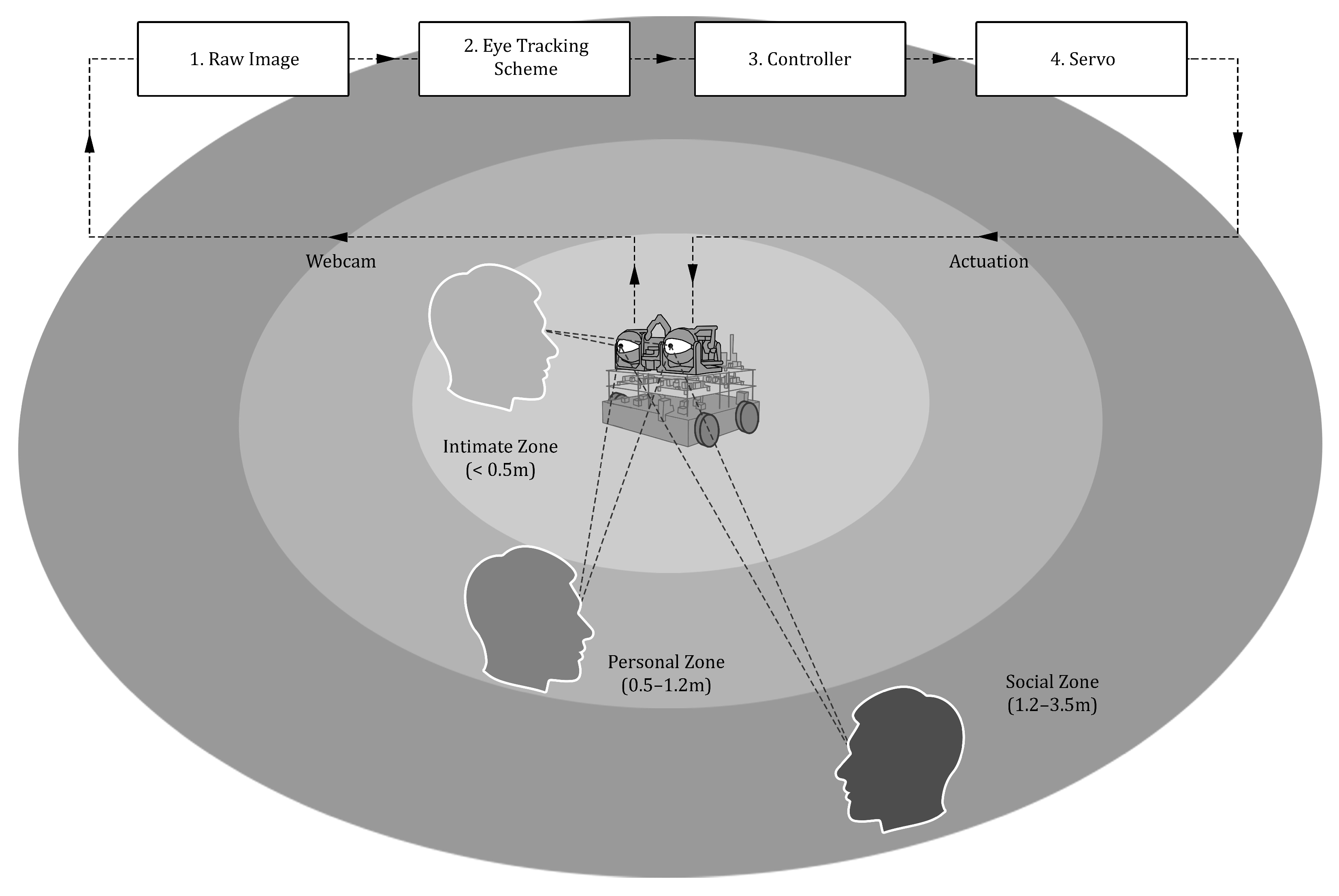
Figure 1. Overview of the proposed system.
Systems 14 00206 g001
Figure 2. Axonometric view of the 3D robotic eyes. There are several servos that are independently operated. Two servos control the top eyelids, and one servo rotates the eyeball sub-assembly along the y-axis. Dashed arrows indicate gaze direction, while dashed curved lines represent the range of motion.
Systems 14 00206 g002
Figure 3. Top view of the 3D robotic eyes. One servo rotates the eyeball sub-assembly along the x-axis. Dashed arrows indicate gaze direction, while dashed curved lines represent the range of motion.
Systems 14 00206 g003
Figure 4. Hardware connection diagram of the robotic eyes.
Systems 14 00206 g004
Figure 5. Photo of 3D robotic eyes integrated with the Smorphi robot.
Systems 14 00206 g005
Figure 6. Experimental setup of the robotic eye integrated with the Smorphi robot.
Systems 14 00206 g006
Figure 7. Considered proxemic zones for the experiments. Experiments 1, 4, 7, and 10 were conducted within the intimate zone (<0.5 m). Experiments 2, 5, 8, and 11 were conducted within the personal zone (0.5–1.2 m). Experiments 3, 6, 9, and 12 were conducted within the social zone (1.2–3.5 m).
Systems 14 00206 g007
Figure 8. System flow for all considered experimental scenarios.
Systems 14 00206 g008
Figure 9. Validation of horizontal x-axis (left) and vertical y-axis (right) gaze test. In the horizontal test, the subject gazed left and right, and in the vertical test, the subject gazed up and down. Screenshot showing the subject’s gaze and the robotic eye’s iris position aligned according to the recorded system timestamp indicated by the dashed line. The robotic eye system mirrored the corresponding direction. The temporal offset represents the response time between detection and actuation.
Systems 14 00206 g009
Figure 10. Validation of combined x- and y-axis gaze test. The subject gazed in four directions, the top-left, bottom-left, bottom-right and top-right. The robotic eye system mirrored the gaze directions. Screenshot showing the subject’s gaze and the robotic eye’s iris position aligned according to the recorded system timestamp indicated by the dashed line. The temporal offset represents the response time between detection and actuation.
Systems 14 00206 g010
Figure 11. The facial landmark framework used from three reference views: the pose landmark model (left), a schematic face illustration (middle), and a screenshot from an actual participant during the experiment (right).
Systems 14 00206 g011
Figure 12. Results for Experiment 1, within the intimate zone (<0.5 m). Subject gazes left, robotic eyes mirror left (left). Subject gazes right, robotic eyes mirror right (middle). Subject gazes left, robotic eyes mirror left (right). Screenshot showing the subject’s gaze and the robotic eye’s iris position aligned according to the recorded system timestamp indicated by the dashed line. The black trace is the webcam detection signal, while the red trace is the observed physical robotic eye actuation. The temporal offset between the two signals corresponds to the response time. Response times were estimated via Pearson’s correlation-based temporal alignment between the two signals.
Systems 14 00206 g012
Figure 13. Results for Experiment 2, within the personal zone (0.5–1.2 m). Subject gazes left, robotic eyes mirror left (left). Subject gazes right, robotic eyes mirror right (middle). Subject gazes left, robotic eyes mirror left (right). The dashed lines indicating the timestamp alignment, trace color coding and response time calculation methodology are consistent with the description provided in the caption of Figure 12.
Systems 14 00206 g013
Figure 14. Results for Experiment 3, within the social zone (1.2–3.5 m). Subject gazes left, robotic eyes mirror left (left). Subject gazes right, robotic eyes mirror right (middle). Subject gazes left, robotic eyes mirror left (right). The dashed lines indicating the timestamp alignment, trace color coding and response time calculation methodology are consistent with the description provided in the caption of Figure 12.
Systems 14 00206 g014
Figure 15. Results for Experiment 4, within the intimate zone (<0.5 m). Subject appears on the right side of the camera frame while the robot starts from the right, robotic eyes gazes right (left). Subject appears in the middle, robotic eyes gazes middle (middle). Subject appears left, robotic eyes gazes left (right). The dashed lines indicating the timestamp alignment, trace color coding and response time calculation methodology are consistent with the description provided in the caption of Figure 12.
Systems 14 00206 g015
Figure 16. Results for Experiment 5, within the personal zone (0.5–1.2 m). Subject appears on the right side of the camera frame while the robot starts from the right, robotic eyes gazes right (left). Subject appears in the middle, robotic eyes gazes middle (middle). Subject appears left, robotic eyes gazes left (right). The dashed lines indicating the timestamp alignment, trace color coding and response time calculation methodology are consistent with the description provided in the caption of Figure 12.
Systems 14 00206 g016
Figure 17. Results for Experiment 6, within the social zone (1.2–3.5 m). Subject appears on the right side of the camera frame while the robot starts from the right, robotic eyes gazes right (left). Subject appears in the middle, robotic eyes gazes middle (middle). Subject appears left, robotic eyes gazes left (right). The dashed lines indicating the timestamp alignment, trace color coding and response time calculation methodology are consistent with the description provided in the caption of Figure 12.
Systems 14 00206 g017
Figure 18. Results for Experiment 7, within the intimate zone (<0.5 m). Subject appears on the right side of the camera frame while the robot starts from the right, robotic eyes gazes right (left). Subject appears in the middle, robotic eyes gazes middle (middle). Subject appears left, robotic eyes gazes left (right). The dashed lines indicating the timestamp alignment, trace color coding and response time calculation methodology are consistent with the description provided in the caption of Figure 12.
Systems 14 00206 g018
Figure 19. Results for Experiment 8, within the personal zone (0.5–1.2 m). Subject appears on the right side of the camera frame while the robot starts from the right, robotic eyes gazes right (left). Subject appears in the middle, robotic eyes gazes middle (middle). Subject appears left, robotic eyes gazes left (right). The dashed lines indicating the timestamp alignment, trace color coding and response time calculation methodology are consistent with the description provided in the caption of Figure 12.
Systems 14 00206 g019
Figure 20. Results for Experiment 9, within the social zone (1.2–3.5 m). Subject appears on the right side of the camera frame while the robot starts from the right, robotic eyes gazes right (left). Subject appears in the middle, robotic eyes gazes middle (middle). Subject appears left, robotic eyes gazes left (right). The dashed lines indicating the timestamp alignment, trace color coding and response time calculation methodology are consistent with the description provided in the caption of Figure 12.
Systems 14 00206 g020
Figure 21. Results for Experiment 10, within the intimate zone (<0.5 m). Subject gazes right, robotic eyes gazes right (left). Subject gazes in the middle, robotic eyes gazes middle (middle). Subject gazes left, robotic eyes gazes left (right). The dashed lines indicating the timestamp alignment, trace color coding and response time calculation methodology are consistent with the description provided in the caption of Figure 12.
Systems 14 00206 g021
Figure 22. Results for Experiment 11, within the personal zone (0.5–1.2 m). Subject gazes right, robotic eyes gazes right (left). Subject gazes in the middle, robotic eyes gazes middle (middle). Subject gazes left, robotic eyes gazes left (right). The dashed lines indicating the timestamp alignment, trace color coding and response time calculation methodology are consistent with the description provided in the caption of Figure 12.
Systems 14 00206 g022
Figure 23. Results for Experiment 12, within the social zone (1.2–3.5 m). Subject gazes right, robotic eyes gazes right (left). Subject gazes in the middle, robotic eyes gazes middle (middle). Subject gazes left, robotic eyes gazes left (right). The dashed lines indicating the timestamp alignment, trace color coding and response time calculation methodology are consistent with the description provided in the caption of Figure 12.
Systems 14 00206 g023
Table 1. Communicative functions of eye gaze in the literature for human–robot interaction.
Communicative FunctionSourceDescription
Mutual gaze (eye contact)[10,13]Establishes interpersonal engagement and social presence; serves as a baseline signal of attention.
Referential (deictic) gaze[17,18]Directs a partner’s attention toward external objects or locations, supporting spatial reference during task-oriented interaction.
Joint attention[19,20]Coordinates shared attention by alternating between mutual gaze and object-directed gaze, supporting learning and instruction.
Gaze aversions[21,22]Brief look-aways that regulate intimacy, signal cognitive load, and smooth conversational flow.
Conversational regulation gaze[13]Regulates conversational dynamics through gaze timing and duration, primarily supporting turn-taking.
Collaborative or manipulative gaze[11]Signals action intent during physical or collaborative tasks (e.g., handovers), supporting prediction and coordination of partner actions.
Expressive gaze[6]Uses eye shape, blink rate, and gaze patterns to convey affective or personality-related cues, independent of task goal.
Table 2. Different proxemics studies in the literature for human–robot interaction.
Focus AreaSourceFindings
Proxemics awareness in HRI[31]Comprehensive review on proxemics for robot navigation and user comfort, with gaze only mentioned briefly.
Likability and gaze influence[32]Mutual gaze increases physical and psychological distancing from disliked robots (participants stand farther away and disclose less); no change for liked robots. Conducted at fixed distances without adaptive gaze.
Navigation and spatial manipulation[33]Socially aware spacing (proxemics) and gaze cues jointly influence perceived robot social presence during hallway crossings, though gaze effects were secondary.
Proxemic factors and comfort[34]Robot gaze direction affects preferred interpersonal distances; direct gaze increases comfort distance (especially for women), while familiarity and traits also play roles. Focus on comfort over dynamic communication.
Collaborative task spacing[35]Identified 2 m as the ideal distance for collaboration and comfort, with indirect effects on connection in communication.
Posture and body orientation[36]Robot stance (sitting vs. standing) impacts approach distances.
Environmental constraints[37]Focused on spatial factors and found that confined spaces elevate stress and diminish comfort.
Social navigation modeling[29]Proxemics-based navigation using Gaussian models and A* planning to support group comfort.
Gaze and proxemics group coordination[38]Robot uses proxemic cues (distance/orientation) to coordinate conversational roles in groups, with gaze adaptation following preset rules.
Adaptive Gaze–Distance Integration[39]Proposed adaptive robot behavior based on combined gaze engagement and interpersonal distance, adjusting motion speed and interaction distance to maintain socially appropriate interaction.
Table 3. Response time-related studies in both human-to-human and human-to-robot interactions.
Response Time BenchmarksSourceContext and Implication
50 ms[40,41](Physiological continuity—HHI). Threshold where humans perceive motion or gaze updates as continuous, forming the perceptual basis of real-time visual continuity.
150–250 ms[42,43](Natural reaction speed—HHI). Typical human saccadic or gaze reaction time; defines the natural human biological response speed to gaze shifts.
200 ms[44](Social contingency—HRI). Qualitative “real-time” threshold for head or gaze responses; within this window, movements are perceived as natural and socially contingent.
500 ms[10,11,28](Attentive and intentional—HRI). Approximate perceptual reference for gaze behavior to be perceived as purposeful. Longer delays might make the robot appear “laggy” but still intentional.
1000 ms[10,28](Upper limit for natural interaction—HRI). Acceptable upper bound for collaborative interaction. Responses are still perceived as intentional but are close to the upper limit for interaction to be perceived as natural.
2000 ms[44](Beyond natural coordination—HRI). Responses beyond this point cause coordinated or reciprocal movement tasks to be harder to synchronize. The interacting subject would rely less on real-time feedback and more on prediction.
4000 ms[45](Loss of coordination—HRI.) Prolonged delays reduce gaze-to-hand following and coordination, impairing fluency.
10,000 ms[45](Presence disruption—HRI). Disrupts engagement and breaks the sense of social presence.
Table 4. Response times, literature benchmarks and Pearson’s correlations across Experiments 1, 2 and 3. Static conditions.
ExperimentResponse Time_msBenchmark ComparisonPearson’s Correlation_r
Experiment 1
Intimate Zone (<0.5 m)
Mean = 329.5
(SD = 23.7)
Natural reaction speed (150–250 ms) [42,43]
Socially contingent behavior (200 ms) [44]
Mean = 0.91
(SD = 0.05)
Experiment 2
Personal Zone (0.5–1.2 m)
Mean = 283.5
(SD = 48.9)
Natural reaction speed (150–250 ms) [42,43]
Socially contingent behavior (200 ms) [44]
Mean = 0.88
(SD = 0.03)
Experiment 3
Social Zone (1.2–3.5 m)
Mean = 286.2
(SD = 34.1)
Natural reaction speed (150–250 ms) [42,43]
Socially contingent behavior (200 ms) [44]
Mean = 0.92
(SD = 0.06)
Table 5. Response times, literature benchmarks and Pearson’s correlations across Experiments 4, 5 and 6. Teleoperated conditions.
ExperimentResponse Time_msBenchmark ComparisonPearson’s Correlation_r
Experiment 4
Intimate Zone (<0.5 m)
Mean = 509.7
(SD = 193.6)
Attentive and intentional
behavior (500 ms) [10,11,28]
Mean = 0.98
(SD = 0.01)
Experiment 5
Personal Zone (0.5–1.2 m)
Mean = 591.2
(SD = 117.0)
Attentive and intentional
behavior (500 ms) [10,11,28]
Mean = 0.97
(SD = 0.01)
Experiment 6
Social Zone (1.2–3.5 m)
Mean = 963.6
(SD = 260.0)
Intentional but close to upper limit for
natural gaze behavior (1000 ms) [10,28]
Mean = 0.95
(SD = 0.02)
Table 6. Response times, literature benchmarks and Pearson’s correlations across Experiments 7, 8 and 9. Autonomous conditions.
ExperimentResponse Time_msBenchmark ComparisonPearson Correlation_r
Experiment 7
Intimate Zone (<0.5 m)
Mean = 356.7
(SD = 28.9)
Attentive and intentional
behavior (500 ms) [10,11,28]
Mean = 0.96
(SD = 0.02)
Experiment 8
Personal Zone (0.5–1.2 m)
Mean = 369.7
(SD = 53.3)
Attentive and intentional
behavior (500 ms) [10,11,28]
Mean = 0.93
(SD = 0.02)
Experiment 9
Social Zone (1.2–3.5 m)
Mean = 668.4
(SD = 135.5)
Attentive and intentional
behavior (500 ms) [10,11,28]
Mean = 0.93
(SD = 0.02)
Table 7. Response times, literature benchmarks and Pearson’s correlations across Experiments 10, 11 and 12. Integrated movement conditions.
ExperimentResponse Time_msBenchmark ComparisonPearson Correlation_r
Experiment 10
Intimate Zone (<0.5 m)
Mean = 568.8
(SD = 55.3)
Attentive and intentional
behavior (500 ms) [10,11,28]
Mean = 0.90
(SD = 0.05)
Experiment 11
Personal Zone (0.5–1.2 m)
Mean = 817.8
(SD = 119.7)
Intentional but close to upper limit for
natural gaze behavior (1000 ms) [10,28]
Mean = 0.88
(SD = 0.02)
Experiment 12
Social Zone (1.2–3.5 m)
Mean = 1175.9
(SD = 577.4)
Intentional but close to upper limit for
natural gaze behavior (1000 ms) [10,28]
Mean = 0.82
(SD = 0.06)
Disclaimer/Publisher’s Note: The statements, opinions and data contained in all publications are solely those of the individual author(s) and contributor(s) and not of MDPI and/or the editor(s). MDPI and/or the editor(s) disclaim responsibility for any injury to people or property resulting from any ideas, methods, instructions or products referred to in the content.