Abstract
The cyclic performance of non-seismically designed reinforced concrete (RC) columns, strengthened with carbon fiber reinforced polymer (CFRP) jackets, was analytically and experimentally investigated herein. Three cantilever column specimens were constructed, incorporating design parameters of the period 1950s–1970s, namely with concrete of a low compressive strength, plain steel bars, widely-spaced ties and inadequate lap splices of reinforcement. The specimens were strengthened using CFRP jackets and were subsequently subjected to cyclic inelastic lateral displacements. The main parameters examined were the length of the lap splices, the acceptable relative bar slipping value and the width of the jackets. The hysteresis behaviors of the enhanced columns were compared, while also being evaluated with respect to those of two original columns and to the seismic performance of a control specimen with continuous reinforcement, tested in a previous work. An analytical formulation was proposed for accurately predicting the seismic responses of the column specimens, comparing the actual shear stress value with the ultimate shear capacity of the concrete in the lap splice region. The test results verified the predictions of the analytical model, regarding the seismic performance of the strengthened columns. Moreover, the influences of the examined parameters in securing the ductile hysteresis performance were evaluated.
Keywords:
CFRP jacket; lap splices; RC columns; cyclic loading; bond-slip; plain bars; seismic rehabilitation 1. Introduction
The design requirements of modern building codes are based on the controllable and hierarchically developed damage control philosophy (capacity design). According to this conception, the preservation of structural integrity can be achieved by appropriately designing the beams to fail in a ductile manner earlier than the adjacent columns and the beam–column connections. This secures the formation of the plastic hinges at the beams in the juncture with the joints, while allowing for the development of increased inelastic deformations and the effective dissipation of seismic energy. As a result, the ductile overall hysteresis performance of modern reinforced concrete (RC) structures can be achieved without necessarily requiring the inelastic response of the columns, while also effectively precluding the damaging of the beam–column joint regions.
The latter, however, is not true for RC structures built prior to the 1960s–1970s. Due to the lack of capacity design approach and the poor detailing of reinforcement, these structures were designed for gravity loads only and, thus, possess numerous structural deficiencies with a decisively detrimental impact on their seismic performance [1,2]. In particular, the hysteresis behavior of these non-ductile RC structures is dominated by brittle failure modes due to limited shear capacity and poor deformability related to insufficient anchorage or/and lap splicing [3,4,5,6,7]. Moreover, the use of concrete with low compressive strength and of plain steel reinforcement further exacerbates the cyclic response by significantly affecting bond–slip relations and, thus, by causing premature excessive bar slipping. As a result, the seismic behavior of the existing pre 1960s–1970s RC structures and, eventually, the safety of residents are seriously jeopardized, since excessive damage incurred from moderate-to-strong earthquakes often results in catastrophic partial or general collapse. It is noteworthy that more than eighty percent of the buildings in Greece were constructed before 1985 and the imposition of modern code provisions, thus, they incorporate poor or no seismic details. Accordingly, these structures require essential retrofitting interventions to show an improved overall hysteresis performance during future strong earthquakes, while preventing catastrophic collapses with huge detrimental social and economic impacts.
For this reason, over the last few decades, various strengthening schemes and techniques for improving the hysteresis behavior of existing non-ductile RC structures were developed. The efficiency of both conventional and innovative materials was also examined. For instance, fiber reinforced polymer (FRP)-wrapping or the steel jacketing of the column critical region was found to significantly increase the column shear strength, energy dissipation capacity and ductility, while the implementation of retrofit schemes, which cause changes in the geometry of columns and of the beam–column joints (i.e., RC jacketing and steel fiber-reinforced concrete jacketing), substantially improves the overall seismic performance by increasing the lateral strength and peak-to-peak stiffness, as well.
The FRP-wrapping (or steel jacketing) of RC columns can be used to confine the critical regions when the primary concern of the adopted earthquake-resistant rehabilitation strategy is the increase in the column energy dissipation capacity, shear strength and ductility. Both strengthening techniques have minimal impact to the column peak-to-peak stiffness, since no considerable changes in the geometry occur by adding the necessary FRP layers (or the thin steel jacket). Nevertheless, the yielding of the inadequately lap-spliced column reinforcement is possible if the necessary confining stress is provided by the jacket, causing a significant increase in the bond stress between steel bars and concrete. Therefore, premature bond-slip failure and the slipping of the bars will be effectively prevented, while the column will develop its nominal flexural moment capacity. Both the steel jacketing and composite material jacketing, however, demonstrate various disadvantages. The most crucial one is the inability to effectively confine and enhance the beam–column joint region, which may cause the concentration of damage at the joint and, eventually, the catastrophic partial or general collapse of the strengthened structure during future earthquake events [8,9,10,11,12,13].
Several experimental and analytical works investigating the effectiveness of FRP jacketing in improving the seismic performance of RC structures are found in literature. El Gawady et al. [14] experimentally investigated they cyclic response of RC columns strengthened by steel jackets or carbon fiber reinforced polymer (CFRP) jackets. Saadatmanesh et al. [15] used the FRP jacketing scheme to retrofit earthquake-damaged column specimens. The strengthened sub-assemblages were subsequently subjected to earthquake type loading and exhibited more stable hysteresis behavior with a lower stiffness degradation ratio compared to the original columns. Furthermore, the enhanced columns developed their nominal flexural moment capacity and displacement ductility. Pavese et al. [16] used composite material jackets to improve the cyclic responses of circular bridge piers subjected to reversed inelastic lateral displacements. The original specimens possessed low shear strength and poor ductility, while the lap splices of reinforcement were located at the potential plastic hinge region. CFRP laminates were used by Pampanin et al. [17] for the earthquake-resistant rehabilitation of poorly detailed existing RC buildings of period 1950s–1970s. The latter incorporated typical structural deficiencies, namely the absence of the confinement of the beam–column joint region, the inadequate length of lap splices of the column longitudinal reinforcement and the deficient anchorage of the beam bars in the joint with end hooks. Both the exterior and interior RC beam-column joint sub-assemblages were strengthened with CFRP laminates and were subsequently subjected to earthquake-type loading. The enhanced specimens exhibited a ductile dissipating hysteresis behavior with the formation of the plastic hinges in the beam or a controlled acceptable minor cracking in the joint panel zone, respectively. Moreover, a partial retrofitting strategy using CFRP laminates for the strengthening of a three-storey three-bay frame structure proved to be notably satisfactory in improving the cyclic response, while preventing the brittle failure of the exterior joints and the formation of a soft-storey mechanism. Yeh and Mo [18] used CFRP sheets for the strengthening of circular and hollow rectangular cross-section RC bridge columns with low shear strength. Karayiannis and Sirkelis [19] investigated the seismic response of RC beam–column joint sub-assemblages strengthened with a combination of epoxy resin injections and CFRP plastics sheets. The retrofitted specimens demonstrated a substantial improvement in their overall hysteresis behavior with respect to the original sub-assemblages. Additionally, a new category of FRP products—super laminates—was recently used for the production of seamless shells around existing columns [20].
It is worth mentioning that the efficiency of a retrofit scheme in improving the seismic behavior of a structural member is highly dependent on the reliable confrontation of all structural deficiencies. Otherwise, the strengthening scheme can be ineffective in the aftermath of moderate-to-strong earthquakes to secure the desirable seismic response. For instance, during the design process of strengthening schemes, practicing Civil Engineers are literally unaware of the real magnitude of the shear forces resisted by the lap splice regions of RC columns. Instead, it is in general inaccurately considered that the reinforcement used to improve the column shear strength is also sufficient to ensure the yielding of the inadequately lap-spliced reinforcement of the existing column. Thus, the seismic performance of the strengthened column may be overestimated, while the premature slipping of reinforcement is possible.
Along these lines, an attempt was made to experimentally investigate the effectiveness of CFRP jacketing in improving the cyclic performance of columns with inadequate lap splices of reinforcement, found in pre 1960s–1970s RC structures. Moreover, an analytical model proposed by Kalogeropoulos and Tsonos [1] was used to precisely calculate the ultimate shear capacity of the lap-splice region and, hence, to accurately predict the hysteresis behavior of the strengthened column specimens. Consequently, the present study provided considerable impetus to the better understanding of the failure mechanisms developing during cycling and of the inadequacies of current code provisions regarding the improvement of the load transfer mechanism between lap-spliced bars.
2. Experimental Program—Material Properties—Strengthening Interventions
Columns are vertical members of the bearing system; hence their cyclic performance decisively affects the overall seismic behavior of RC structures, especially the framed ones. As a result, these elements should (if possible) remain elastic during seismic excitations, in order that damage caused by brittle failure mechanisms, namely brittle shear or/and premature bar slipping, can definitely be precluded. Therefore, the columns should be designed to possess a ductile hysteresis response governed by the flexural yielding of reinforcement at the plastic hinges and overstrength development due to the strain hardening of steel bars. The above is the sine qua non factor for ensuring effective seismic energy dissipation, damage control and collapse prevention. Moreover, this condition should necessarily be satisfied not only in the case of modern RC structures, but also when designing retrofit schemes for improving the seismic behavior of existing poorly detailed RC columns.
The present study aims to experimentally and analytically investigate the effectiveness of CFRP jacketing system in improving the load transfer mechanism between the lap-spliced reinforcing bars of substandard columns, to allow for steel yielding and the development of the column’s nominal flexural moment capacity. Thus, an experimental program was conducted for three cantilever column specimens of 1:1.5 scale. The original specimens (S1, D1 and D2) were representative of columns found in typical pre 1960s–1970s RC structures, namely with concrete of low compressive strength, plain steel reinforcement S220, transverse reinforcement consisting of ties with ninety-degree hook ends spaced at 200 mm and lap splices of reinforcement with inadequate length equal to twenty-four-times (specimen S1) or twenty-times (specimens D1 and D2) the bar diameter. Dimensions and cross-section details of the specimens are illustrated in Figure 1. The reinforcements of the specimens were inserted into wooden molds, while subsequently the concrete was poured and vibrated. The concrete compression strength of the specimens was measured by using 150 × 300 mm cylinder compression tests. The strength values after twenty-eight days are shown in Table 1.
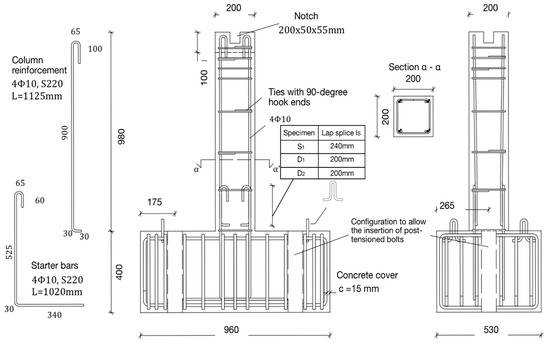
Figure 1.
Dimensions (in mm) and cross-section details of the original specimens.

Table 1.
Experimental program—Original and strengthened column specimens.
Specimens S1, D1 and D2 were retrofitted prior to the imposition of the earthquake-type loading by the CFRP-wrapping of the column critical region. The CFRP jacket applied to the columns consisted of either one (specimens S1 and D1) or two layers of textile (specimen D2). The enhanced columns were designated FS1, FD1 and FD2, respectively. The strengthening procedure included several steps of carefully executed interventions. In particular, using a spinning wheel, the surface in the circumference of the column along the critical height (600 mm) was rubbed until the aggregates were revealed, as shown in Figure 2a. This aimed to improve contact with the CFRP textile and prevent the possible damaging of the strengthening material due to surface imperfections and protrusions. Moreover, using the appropriate equipment, the column edges were curved to preclude the possible tearing of the textile material, while allowing the improved confinement of the steel bars in the corners by the CFRP jacket, as shown in Figure 2b. The radius of edge curvature equaled to two and a half times the width of the concrete cover [21]. Subsequently, the column surface was cleaned from dust with air pressure and covered with epoxy resin, as shown in Figure 2c. The length of the CFRP textile, which was used to confine the columns, equaled to 900 mm or 1700 mm for the CFRP jackets of one layer or two layers, respectively. The CFRP jacket started 20 mm above the foundation block of the specimens, while the textile was carefully applied to the surface with the direction of the fibers perpendicular to the column axis, as shown in Figure 2c,d. The latter is crucial for securing the effective confinement of the column critical region. Afterwards, a knife was used to press the fabric on the surface and to allow full integration to the resin matrix, as shown in Figure 2c. Meanwhile, the air that was trapped in cavities was removed. After wrapping the column with the first layer of the CFRP textile, the strengthening material was covered with epoxy resin (specimens S1 and D1). In the case of specimen D2, a second layer of the CFRP textile was also used for confining the column, as shown in Figure 2d. The material properties of the CFRP textile and of the epoxy resin are shown in Table 2 and Table 3, respectively. In order to evaluate the seismic performance and the efficiency of the CFRP-jacketing of the pre-earthquake strengthened specimens, FS1, FD1 and FD2, the overall hysteresis behavior was compared to the cyclic responses of two original column specimens, O1 and O2, which were similar to columns S1, D1 and D2, as well as to the response of a control specimen, C1, with continuous reinforcement. Specimens O1, O2 and C1 were tested in a previous work of Kalogeropoulos and Tsonos [1]. In particular, specimens D1 and D2, had the same reinforcement details and lap splices, with length equal to 200 mm, as the original column O1, while specimen S1 was similar to the original column O2, with lap splices of 240 mm length.
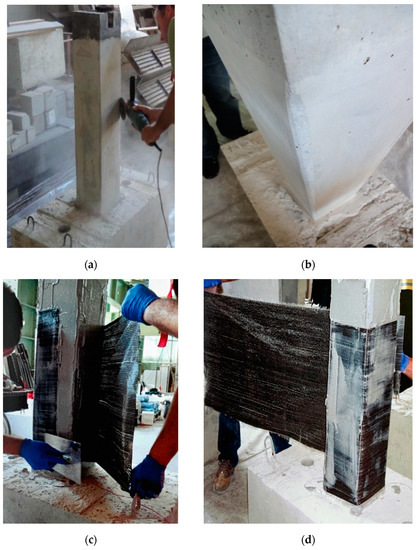
Figure 2.
Retrofit process. (a) Smoothing of the circumferential column surface; (b) curving of the column edges; (c) wrapping of the first layer of CFRP textile—full integration of the textile to the resin matrix; (d) wrapping of the second layer of the CFRP textile.
Table 2.
Material properties of the carbon fiber textile used for the strengthening of the specimens.
Table 3.
Material properties of the two-part epoxy resin used for constructing the CFRP jackets.
The required width, , of the confining material, which is directly related to the number of layers of the CFRP textile, was calculated according to the provisions of the Greek Code for Interventions (GCI 2017) [22]. The latter introduces Equation (1), where is the width of the CFRP jacket; is the cross-section area of the jacket; is the distance between stirrups or FRP strips; is the diameter of the lap-spliced bars; is the characteristic concrete strength; = is the yield stress of the plain lap-spliced bars; is the lap-splice length; c is the concrete cover; = 0.9 is the modulus of elasticity of the CFRP jacket; is the mean tensile strength of the concrete; w is the dilation of the concrete cracking between the column lap-spliced bars, equal to w = 0.33 mm, which corresponds to the maximum accepted value of relative slipping, s = 0.4 mm or 1.5 mm, according to the GCI [22]; = 2 mm is the critical friction slippage.
The seismic tests of the strengthened column specimens were conducted in the test setup, shown in Figure 3, which is located at the Laboratory of Reinforced Concrete and Masonry Structures of the Aristotle University of Thessaloniki. The columns were loaded transversely under a constant axial loading of 150 kN, following the displacement-controlled schedule, illustrated in Figure 4. It should be noted that an increase in the compressive axial force would have a detrimental impact on the behavior of the CFRP-strengthened columns, causing early relative slipping of the lap-spliced reinforcing bars and, eventually, the premature failure of the lap splices. Additionally, if lap splice failure is effectively prevented and the buckling of the longitudinal column reinforcement occurs, then the damage of the concrete would be accelerated, resulting in the early failure of the CFRP textile layers. The specimens were fixed to the test frame with post-tensioned bars (bolts). As a result, the horizontal and vertical displacement and the rotation of the foundation block of each specimen were restrained. The axial load was imposed to the column by a one-way actuator lay on a rolling carrier, as shown in Figure 3, while controlled to remain constant throughout testing. Moreover, a two-way actuator was used for applying the lateral seismic loading perpendicular to the column axis by slowly displacing the column-free ends of the specimens. A calibrated linear variable differential transducer (LVDT) was used to control the load point displacement. Meanwhile, the shear resistance of the column was measured by a load cell, as shown in Figure 3. The instrumentation also included electrical resistant strain gauges, which were installed on the longitudinal reinforcing bars of each column to record strain variations during cycling and to ascertain if the yielding of the reinforcement was achieved or not. It is noteworthy that both the test setup, as well as the instrumentation used, were completely new, and they were recently measured by the supplying companies, which found that the error in measurements was particularly small and insignificant. Thus, it was ignored with minimal impact in the final results.
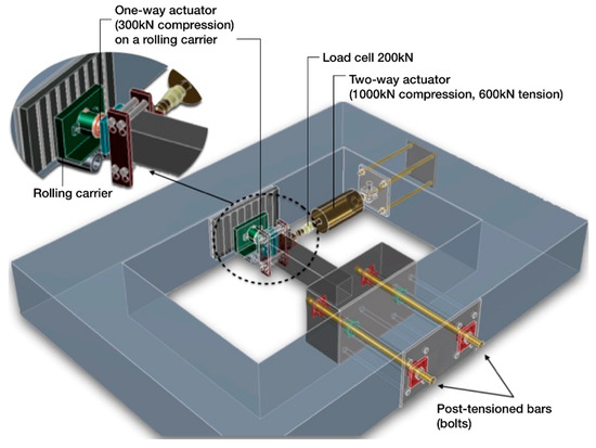
Figure 3.
Test setup and instrumentation used.
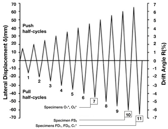
Figure 4.
Lateral displacement history. Specimens O1, O2 and C1 were tested in a previous work [1].
The seismic loading sequence was established to capture critical issues of the element capacity—for instance, the ultimate limit state of the column. Given that the inelastic deformations cause cumulative damage, while the behavior of the column is mainly demonstrated by the envelope curves, a constantly ascending lateral displacement history with one cycle per amplitude of displacement was adopted, without considerable influence on the seismic performance of the specimens. An original specimen was used to determine the steps of the earthquake-type loading and was at first loaded to its yield displacement, after which a significant decrease in stiffness occurs. This was measured from the plot of the resisted shear force-versus-displacement of the specimen, while it was also verified by the yielding of the longitudinal column reinforcement using strain gauges. The loading was continued in the same direction (push cycles) to 1.5 times the yield displacement and the specimen was subsequently unloaded and loaded in the other direction (pull cycles) to the same lateral displacement. After the first cycle of loading, the maximum displacement of each subsequent cycle was increased incrementally by 0.5 times the yield displacement [23,24,25].
It is worth mentioning that the column specimens were subjected to earthquake-type loading with a strain rate corresponding to static conditions. However, during a dynamic phenomenon, such as an earthquake event, the strain rate is higher than that corresponding to static conditions [26,27,28]. Consequently, the strengths exhibited by the column specimens during testing were somewhat lower than the strengths they would exhibit if subjected to displacement histories similar to actual seismic events.
3. Interpretation of the Experimental Results and Implementation of the Proposed Analytical Model
The pre-earthquake strengthened column specimens, FS1, FD1 and FD2, were subjected to a large number of incremental amplitudes of reversed lateral displacements to simulate the equivalent effect of strong seismic excitations. The hysteresis performances of the specimens were subsequently evaluated using data acquired from the experimental equipment during testing. In particular, the effectiveness of the CFRP jackets in improving the load transferring conditions between the lap-spliced bars, as well as the reliability of the GCI provisions, were investigated by evaluating the perceived lateral strength, as shown in Figure 5, peak-to-peak stiffness, as shown in Figure 6a, and energy dissipation capacity, as shown in Figure 6b.
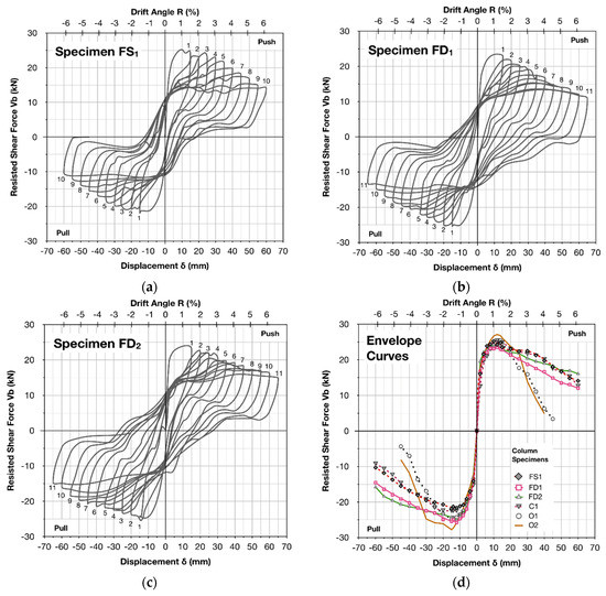
Figure 5.
Plots of resisted shear force-versus-displacement of the strengthened column specimens, (a) FS1, (b) FD1, (c) FD2 and (d) envelope curves. Specimens O1, O2 and C1 were tested previously [1].

Figure 6.
(a) Peak-to-peak stiffness and (b) energy dissipation capacity of the CFRP-strengthened specimens FS1, FD1 and FD2 with respect to specimens O1, O2 and C1 [1].
3.1. Interpretation of the Seismic Behaviour of the Strengthened Specimens
The original specimens (S1, D1 and D2) were designed with poor seismic details in order to be similar to specimens O1 and O2, which were representative of columns found in pre 1960s–1970s RC buildings and were tested in a previous work of Kalogeropoulos and Tsonos [1]. In particular, D1 and D2 were similar to specimen O1, while S1 was similar to specimen O2. Therefore, the efficiency of the strengthening scheme, applied to the pre-earthquake strengthened columns FS1, FD1 and FD2, was also evaluated with respect to the hysteresis performance of the original specimens, O1 and O2, as shown in Figure 5d. The latter exhibited brittle premature lap-splice failure, followed by excessive bar slipping and the rapid degradation of lateral strength, peak-to-peak stiffness and energy dissipation capacity, while finally collapsing due to the loss of axial load carrying capacity. Contrariwise, the CFRP jacketing of specimens FS1, FD1 and FD2 provided additional confinement to the critical region of the columns, while improving the load transfer mechanism between the lap-spliced reinforcement. Hence, the overall hysteresis behavior of the strengthened columns with the CFRP jacket was improved and was close to the cyclic response of the control specimen C1, which had continuous bars without lap splices and was also tested previously, as shown in Figure 5d [1].
Specimen FS1 was strengthened according to Equation (1) with one layer of CFRP textile, while it was subjected to ten cycles of inelastic lateral displacement increments. The maximum accepted value of relative bar slipping, s, in Equation (1) was considered equal to 0.4 mm. The column showed mild degradation of the lateral strength and peak-to-peak stiffness and a continuous increase in the hysteretic energy dissipation capacity values during cycling. This was clearly illustrated in the plot of resisted shear force-versus-displacement of the specimen, as shown in Figure 5a. During the first cycle of the earthquake-type loading, the main flexural crack was formed at the base of the column. This crack gradually dilated with the increase in lateral displacement. Moreover, during the third cycle of loading, a hairline crack was formed on the CFRP jacket exactly in the position where the lap-splicing of reinforcement was terminated (240 mm from the column base). The cracking of the CFRP jacket propagated progressively in the circumference of the strengthened column FS1, as shown in Figure 7a. Nevertheless, the application of the CFRP textile was successful, since no detachment of the strengthening material from the column surface was observed throughout testing. The confinement offered by the CFRP jacket improved the bond between the steel bars and concrete; however, it was inadequate to preclude the slipping of the bars, especially for the increased values of lateral drift angle, R (R > 5.10 percent). As a result, specimen FS1 exhibited a brittle failure mode characterized by the premature slipping of the lap-spliced bars. For drift angle, R, equal to 6.12 percent, the residual deformation of the column-free end equaled to 50 mm, while the rotation of the column axis equaled to 0.05 rad. The value of the resisted shear force of specimen FS1 was almost the same for the first push half-cycle (25.21 kN) and the first pull half-cycle (21.88 kN) of the earthquake-type loading. Subsequently, in the second push half-cycle and pull half-cycle, the strength values were slightly reduced due to the slipping of the bars. The latter is also reflected by the lower steel strain value developed with respect to the first cycle of loading, as shown in Figure 8b and Figure 9a. An increase in the lateral strength of FS1 was observed for the third cycle with respect to the second cycle. Afterwards, the resisted shear force of the specimen showed a mild reduction, while at the end of testing the column lateral strength equaled to 55 percent of its initial value during the first cycle of loading. From the increasing area of the hysteresis loops of specimen FS1, it was clearly demonstrated that the strengthened column dissipated continuously incremented values of seismic energy during consecutive cycles of the earthquake-type loading. Moreover, in Figure 6b it can be observed that, for each cycle of the seismic loading, the energy dissipation capacity of FS1 and that of the control specimen C1 were almost similar, while the energy dissipation ratio value FS1/C1 was stable and equal to almost 70 percent. The values of lateral strength and of the peak-to-peak stiffness of specimens FS1 and C1 were similar throughout testing. Eventually, the strengthened specimen FS1 exhibited a seismic performance which was closer to that of the control specimen, C1, while showing a significantly improved cyclic response with respect to the corresponding original column, O2, as shown in Figure 5 and Figure 6. The use of the CFRP jacket also improved the failure mode of FS1, as shown in Figure 7a, with respect to that of the corresponding original column, O2, while preventing the catastrophic collapse of the column due to the loss of axial load carrying capacity.
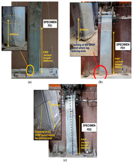
Figure 7.
Failure mode of the column specimens strengthened with jacket of one layer (a,b) and two layers (c) of CFRP textile.
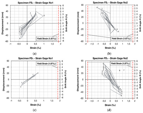
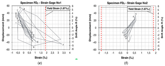
Figure 8.
Plots of displacement-versus-strain measured by strain gauges which were attached on the steel bars of specimens FS1 (a,b), FD1 (c,d) and FD2 (e,f).
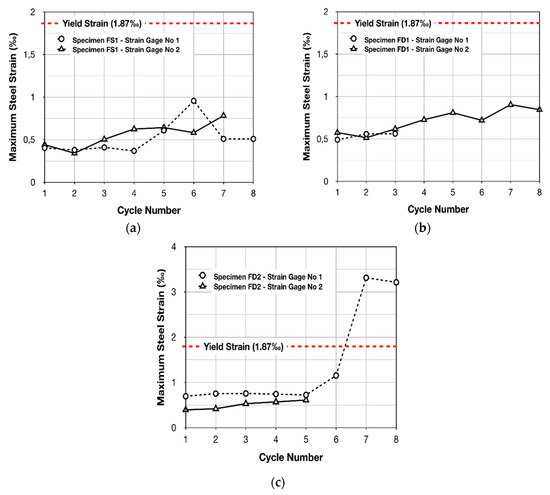
Figure 9.
Maximum steel strain values of (a) specimen FS1, (b) specimen FD1 and (c) specimen FD2.
Specimens FD1 and FD2 were retrofitted by the CFRP wrapping of the critical region with one layer and with two layers of the textile, respectively. Equation (1) was used to calculate the necessary number of layers of the composite material. Both specimens had inadequate lap splices of reinforcement of 200 mm length. According to the GCI [22] in Equation (1) an increased value of the maximum acceptable relative slipping, s, between the lap-spliced bars equal to s = 1.5 mm was considered in the case of specimen FD1. The corresponding value in the case of specimen FD2 was more conservative and equaled to 0.4 mm. Both strengthened specimens, FD1 and FD2, were subjected to eleven cycles of incremental amplitudes of inelastic lateral displacements. During the first cycle of loading, the main flexural crack and a few more hairline flexural cracks were formed in the concrete at the column base, which subsequently dilated during the consecutive cycles. Moreover, a minor cracking of the CFRP jacket was formed during the fourth cycle (specimen FD1) and the tenth cycle of loading (specimen FD2), at the exact position where the lap splicing of the bars was terminated (at a distance equal to 200 mm from the column base), as shown in Figure 7b,c. The latter occurred due to the cracking of the concrete underneath the CFRP jacket. Nevertheless, no detachment of the jacket from the column surface was observed during testing, thus, the application of the CFRP textile was eventually successful. Both strengthened columns FD1 and FD2 exhibited a failure mode of mixed-type, combining flexural failure with the slipping of the lap-spliced bars. However, the increased slipping of reinforcement was only noticed for drift angle values, R, greater than 4.59 percent. Figure 7b shows the significant dilation (equal to approximately 2 cm) of the main crack at the base of column FD1, which was observed for a lateral drift angle value, R, of 6.63 percent (for the peak displacement of the eleventh pull half-cycle). Nevertheless, at the end of the earthquake-type loading, the residual deformation of specimen FD1 was equal to 1 cm, while the rotation of the column axis equaled to 0.01 rad, as shown in Figure 7b. From the plot of resisted shear force-versus-displacement, and from the envelope curves shown in Figure 5b,d, it was clearly demonstrated that the strengthened specimen FD1 exhibited a dissipating hysteresis behavior with a mild reduction in lateral strength and peak-to-peak stiffness during cycling, which was similar to that of the control specimen, C1, with the continuous reinforcing bars. This is also true for specimen FD2. Moreover, the confinement provided by the CFRP jacket effectively prevented the catastrophic collapse of the strengthened specimens FD1 and FD2, while ensuring the development of increased steel strain values, which were significantly higher than yield strain in the case of specimen FD2, as shown in Figure 8e and Figure 9c. As a result, the overall seismic behavior of the strengthened specimens FD1 and FD2 were significantly improved with respect to the performance of the corresponding original column, O1, while a substantial improvement in the energy dissipation capacity and the ductility of FD1 and FD2 was also achieved.
3.2. Monitoring of the Steel Bar Micro-Strain
Premature excessive slipping of the inadequately lap-spliced reinforcing bars dominates the behavior of columns of existing pre 1960s–1970s RC structures during moderate-to-strong seismic excitations. Therefore, the overall hysteresis performance and structural integrity are seriously jeopardized, due to the brittle failure mode of the columns, while partial or general collapse is possible. Accordingly, the applied retrofit scheme should be appropriately designed to preclude early bond-slip failure or/and the brittle shear failure of the column, while effectively securing the yielding of the lap-spliced reinforcement. Thus, the strengthened columns would demonstrate a ductile hysteresis response, while developing the nominal flexural moment capacity.
Along these lines, electrical resistant strain gauges were attached to the lap-spliced bars of the column specimens to allow for the monitoring of steel strain variations during the earthquake-type loading and to ascertain if the yielding of the bars was achieved. The exact location of each strain gauge is presented in Figure 10, while in Figure 8 and Figure 9, the plots of the load point displacement-versus-strain of reinforcement and the plots of maximum steel strain per cycle of loading are illustrated, respectively. Consequently, critical information about the specimens’ responses during the reversed inelastic lateral deformations was provided. In particular, strain values lower than the yielding strain of the S220 reinforcing bars were measured in the case of the strengthened specimens FS1 and FD1, which were retrofitted by wrapping one layer of CFRP textile around the critical column region, as shown in Figure 8a–d and Figure 9a,b. Thus, from the measurements of the strain gauges, it was demonstrated that the confinement provided by the CFRP jackets of specimens FS1 and FD1 was insufficient to allow for the yielding of the lap-spliced bars. Contrariwise, the continuously increasing steel strain values during consecutive cycles of the loading of specimen FD2 indicate the absence of bar slipping [29], while the measured strain significantly exceeded the steel yielding strain 1.87‰, as shown in Figure 8e,f and Figure 9c. This clearly demonstrated the satisfactory enhancement provided by the CFRP jacket of specimen FD2.
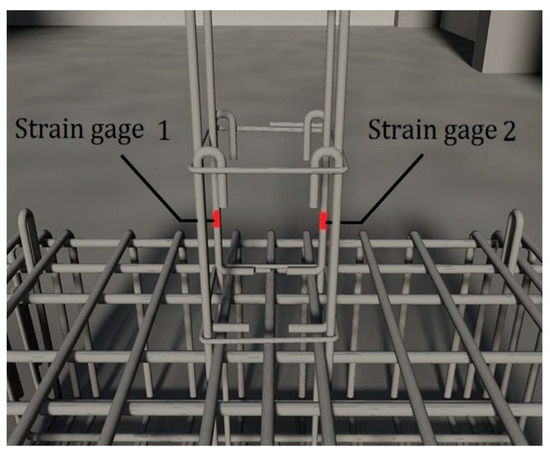
Figure 10.
Location of strain gages attached to the lap-spliced bars of specimens FS1, FD1 and FD2.
3.3. Theoretical Considerations
An analytical formulation was recently presented by Kalogeropoulos and Tsonos [1] for controlling the adequacy of the lap splices found in columns of both existing pre 1960s–1970s and modern RC structures and for accurately predicting the seismic behavior of the columns. The methodology is also applied during the retrofit process of existing RC structures to precisely determine the confinement provided by the jacket (i.e., RC jacket, steel jacket and FRP jacket) which is necessary to prevent premature lap-splice failure, while satisfactorily improving bond stress and the load transfer mechanism. Therefore, the strengthening schemes applied to columns found in existing RC structures can be appropriately designed to provide adequate confinement to the column critical region, where lap splices of reinforcement are located and, hence, allow for the yielding of the inadequately lap-spliced bars. The formulation is a modified version of the analytical model proposed by Tsonos [30,31,32]. The latter is applied to predict the ultimate shear capacity of beam–column joints of old, modern and strengthened RC structures and is also applied in the beam–column joints of modern and strengthened RC structures for effectively securing the concentration of damage and the formation of plastic hinges in the beam(s), while the columns and especially the beam–column joint regions remain intact during strong seismic excitations. Thus, the brittle shear failure of the joints is inhibited. The model can also be implemented to compute the necessary reinforcements of short structural members, namely, columns, beams and RC walls, for satisfactorily precluding brittle shear damaging. The validity of the analytical model was checked using numerous specimens of Tsonos and data from experimental works found in literature, while it was proved to be particularly accurate in predicting the seismic response of the RC members [33].
In Figure 11 and Figure 12, the details of the lap-spliced column longitudinal bars are illustrated. The lap splices of reinforcement are located in the potential plastic hinge region of the column, just above the floor slab. During an earthquake event, tensile and compressive forces are developing in the lap-spliced bars, acting in opposite directions. As a result, the bond stresses between concrete and steel in the circumference of the bars cause the diagonal compression of the concrete in every single section “abcd”, as shown in Figure 12a. These shear forces, acting on a 45 degree angle [34], are resisted by the concrete compression struts that act between the diagonally opposite corners of each rectangular section “abcd”. Moreover, the diagonal compression strut mechanism depends on the concrete strength. Therefore, the ultimate concrete strength under compression/tension controls the ultimate strength of the lap splice. Indeed, the failure of the concrete causes the limitation of strength of the lap splice, due to the gradual crushing along the cross-diagonal cracks and especially along the potential failure plane, KLMN, as shown in Figure 12. Meanwhile, the slipping of the bars occurs.
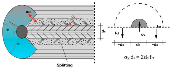
Figure 11.
Critical concrete section where splitting cracks are forming due to the exhaustion of the concrete tensile strength in the circumference of the bar.
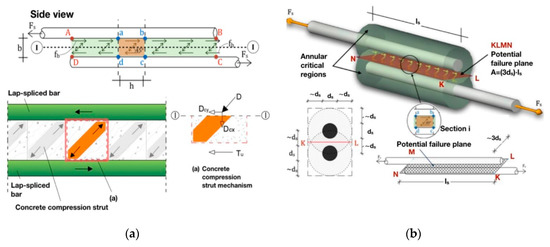
Figure 12.
(a) Forces acting in the lap splice region through section I-I from the concrete compression strut mechanism; (b) annular critical regions and potential failure plane (KLMN).
The calculation of ultimate shear strength of the concrete requires the precise determination of the potential failure plane dimensions. The latter has length equal to the lap-splice length, = (NK) = (ML), while its width (NM) = (KL) depends on the tensile strength of the concrete, , perpendicular to the bars. In particular, when the bond stress in the circumference of the column becomes equal to 2, splitting cracks form in the concrete, perpendicular to the bars, as shown in Figure 11. Thus, an annular critical space around each lap-spliced bar is formed, with a diameter equal to three times the bar diameter, , and length equal to the lap splice length, , as shown in Figure 12b. Eventually, the area of the potential failure plane equals to . According to the analytical model [1], the ultimate strength of the lap splice is given by Equation (2), where values of x and ψ are given by Equations (3) and (4), respectively, while the aspect ratio value α = h/b is always equal to 1.0 [26]. Thus, the ultimate shear stress, is calculated from the system of Equations (2)–(4), where is the increased concrete compressive strength due to the confinement provided by the CFRP jacket, according to Equations (5) and (6) [27]. Subsequently, the design value of parameter γ, (), and the value , which corresponds to the shear stress developed along the actual length of the lap splice, , are computed and compared with .
In particular, when the calculated shear stress, , is lower than the ultimate strength, , then the predicted actual value of the lap splice shear stress, , will be near , because the lap splice permits the yielding of reinforcement. Contrarily, when the computed shear stress, , is equal to or greater than the ultimate shear capacity of concrete in the lap splice region, , then the lap splice fails prematurely, while excessive bar slipping occurs prior to the yielding of reinforcement. In this case, the following should be considered for the predicted actual value of shear stress developing in the lap splice region, :
- Due to the beneficial influence of confinement on the bond stress between concrete and steel bars, the formation and rapid propagation of splitting cracks in the concrete are prevented. Therefore, even if poor confinement is provided to the lap splice region, which is inadequate to secure the yielding of the bars, the observed strain of reinforcement will be slightly increased with respect to the strain values of totally unconfined lap-spliced bars. Consequently, failure is caused by the exhaustion of the ultimate concrete shear capacity, , while the predicted actual value of the lap splice shear stress, , will be near .
- For unconfined inadequately lap-spliced reinforcing bars, two distinguished sub-cases exist:
- The length of the lap splice, , is lower than the necessary length, , to secure the yielding of reinforcement (). Then, failure results from the exhaustion of the ultimate concrete shear capacity,, while the predicted actual value of the lap splice shear stress,, will be near .
- The length of the lap splice,, is extremely short compared to the necessary length, , for securing the yielding of reinforcement (). Then, premature bond-slip failure cause the excessive slipping (pullout) of reinforcement (especially of plain bars) prior to the exhaustion of the ultimate concrete shear capacity,, while the predicted actual value of the lap splice shear stress, , will be near .
Data acquired during the testing of specimens FS1, FD1 and FD2 were used to check the validity of the proposed analytical formulation. The latter was also previously checked [1] using experimental data from eight column specimens tested in the Laboratory of Reinforced Concrete Structures and Masonry Buildings of the Aristotle University of Thessaloniki, as well as data from 23 similar experiments found in the literature. The shear capacities and the predicted actual values of the lap splice shear stress are shown in Table 4. The acquired experimental data verified the predictions of the analytical model for the response of the lap splices of specimens FS1, FD1 and FD2 during cycling. In particular, it was accurately predicted that, in the case of specimens FS1 and FD1, premature excessive slipping of the lap-spliced reinforcement occurred prior to the development of the nominal flexural moment capacity, due to the exhaustion of the ultimate shear capacity of the concrete along the potential failure plane (). Contrarily, in the case of the strengthened column FD2, the adequacy of confinement provided by the CFRP jacket for securing the yielding of the lap-spliced bars () was also predicted by the analytical model.
Table 4.
Predicted values of the concrete shear stress in the potential failure plane.
4. Discussion
An experimental program was conducted herein for three cantilever column specimens of 1:1.5 scale. The latter incorporated poor seismic details, while they were pre-earthquake strengthened by the CFRP-wrapping of the column along the critical height, where the lap splices of reinforcement are located. The main parameters examined were the length of lap splices, the acceptable relative bar slipping value and the width of the CFRP jackets. A thorough and comprehensive interpretation of the overall hysteresis behavior of the strengthened columns was attempted, based on the results from both the experimental program and the implementation of the proposed analytical model. Moreover, the influence of the examined parameters in securing the ductile hysteresis performance of the strengthened specimens was evaluated.
Comparing the failure modes of the strengthened specimens FS1, FD1 and FD2 with those of the corresponding original columns O1 and O2, which were tested in a previous work [1], it was concluded that the catastrophic collapse of non-ductile RC columns, with lap splices of reinforcement of insufficient length and with low shear strength, may be effectively precluded by providing adequate confinement to the column critical region. The latter, however, requires a thorough understanding of the lap splice failure mechanism and the precise computation of the ultimate shear capacity of concrete along the potential failure plane between the lap-spliced bars. Indeed, the proposed analytical model satisfactorily predicted the cyclic performance of the strengthened columns. Thus, by implementing the analytical model, the applied retrofit scheme can be appropriately designed to provide the necessary confinement for securing the yielding of the inadequately lap-spliced column reinforcement before excessive slipping of the bars occurs. For instance, the confinement provided by the CFRP jackets effectively prevented the rapid degradation of lateral strength, peak-to-peak stiffness and the energy dissipation capacity of the enhanced columns, FS1, FD1 and FD2, while allowing for a more dissipating hysteresis behavior with respect to the original columns, O1 and O2. Additionally, in the case of specimen FD2, the yielding of reinforcement was achieved, while the column performed similarly to the control specimen, C1, which had continuous reinforcing bars [1].
It was also clearly demonstrated that the length of the lap splices significantly affects the cyclic response of RC columns, particularly when unconfined and/or plain bars are used. Therefore, short lap splices require significantly increased confining stress for preventing early bond-slip failure and the possible collapse of the column. As a result, an increased number of layers of CFRP textile is necessary to be wrapped around the column critical region to effectively improve load transferring between the lap-spliced bars. Moreover, in Equation (1) it is crucial to control the acceptable value of relative bar slipping, s, to remain relatively low (equal to 0.4 mm). The latter is crucial for accepting a lower level of damage, while significantly increasing the demand for additional confinement to be provided by the jacket for securing the yielding of the lap-spliced reinforcement. Higher values of relative bar slipping, s (i.e., s = 1.5 mm), especially when combined with the short length of lap splices and with the use of plain steel reinforcement, result in premature bond-slip failure and excessive slipping of the lap-spliced reinforcement due to inadequate confinement provided by the jacket.
Ultimately, the satisfactory seismic performance of non-ductile RC columns, strengthened by CFRP jacketing, is possible by implementing the proposed analytical formulation and by accepting a lower level of damage. Thus, the brittle premature lap spice failure may be effectively precluded, while the strengthened columns exhibit a desirable ductile dissipating hysteresis behavior. Moreover, the satisfactory seismic response of the strengthened RC structure is secured by implementing the analytical model of Tsonos in the beam–column joint regions and its modified version presented herein in the lap splice region of the columns’ reinforcement. This allows for the concentration of damage and the formation of the plastic hinges solely in the beam(s), while the brittle failure of the columns and of beam–column joint regions are effectively precluded.
Author Contributions
The authors contributed significantly to this study, discussed the results and prepared the manuscript. G.K. designed the specimens and performed the seismic tests under the supervision of Professor A.-D.T., who designed the experiments. Interpretation and analysis of the experimental results, as well as modification of the analytical formulation of Tsonos to be applied in the lap splice region of the column specimens was also made by G.K. under the guidance of Professor A.-D.T. All authors have read and agreed to the published version of the manuscript.
Funding
This research received no external funding.
Acknowledgments
The authors gratefully acknowledge the kind donation of the steel reinforcement by Sidenor, S.A. industry, while also acknowledging the ISOMAT S.A. industry for the free construction of the CFRP jackets. Moreover, the authors would like to express their thanks to the Dipl. Civil Engineers, Alexander Anatolakis, Alexia Chalkia, Georgia Kyrkousi and Ioanna Stavridou for their contributions in the stage of measurement acquirement during the seismic tests.
Conflicts of Interest
The authors declare no conflict of interest.
References
- Kalogeropoulos, G.; Tsonos, A.D. Improvement of the cyclic response of RC columns with inadequate lap splices—Experimental and analytical investigation. Earthq. Struct. 2019, 16, 279–293. [Google Scholar] [CrossRef]
- Kalogeropoulos, G.; Tsonos, A.D.; Konstantinidis, D. Seismic behaviour of RC columns with welded rebars or mechanical splices of reinforcement. Earthq. Struct. 2019, 17, 297–306. [Google Scholar] [CrossRef]
- Karayannis, C.; Golias, E. Full scale tests of RC joints with minor to moderate seismic damage repaired using C-FRP sheets. Earthq. Struct. 2018, 15, 617–627. [Google Scholar] [CrossRef]
- Chalioris, C.; Bantilas, K. Shear strength of reinforced concrete beam-column joints with crossed inclined bars. Eng. Struct. 2017, 140, 241–255. [Google Scholar] [CrossRef]
- Kakaletsis, D.; David, K.; Karayannis, C. Effectiveness of some conventional seismic retrofitting techniques for bare and infilled R/C frame. Struct. Eng. Mech. 2011, 39, 499–520. [Google Scholar] [CrossRef]
- Karayannis, C. Mechanics of external RC beam-colum joints with rectangular spiral shear reinforcement: Experimental verification. J. Mecc. 2015, 50, 311–322. [Google Scholar] [CrossRef]
- Kalogeropoulos, G.; Tsonos, A.-D. Effectiveness of RC jacketing of substandard RC columns with short lap splices. Struct Monit. Maint. 2014, 1, 273–292. [Google Scholar]
- Paulay, T.; Priestley, M.J.N. Seismic Design of Reinforced Concrete and Masonry Buildings; John Wiley and Sons: New York, NY, USA, 1992. [Google Scholar]
- Tsonos, A.G. Effectiveness of CFRP jackets in post-earthquake and pre-earthquake retrofitting of beam-column subassemblages. Struct. Eng. Mech. 2007, 27, 393–408. [Google Scholar] [CrossRef]
- Tsonos, A.-D. Effectiveness of CFRP-jackets and RC-jackets in post-earthquake and pre-earthquake retrofitting of beam-column subassemblages. Eng. Struct. 2008, 30, 777–793. [Google Scholar] [CrossRef]
- Karayannis, C.; Kosmidou, P.-M.; Chalioris, C. Reinforced concrete beams with carbon-fiber-reinforced polymer bars—Experimental Study. Fibers 2018, 6, 99. [Google Scholar] [CrossRef]
- Chalioris, C.E.; Kosmidou, P.-M.K.; Papadopoulos, N.A. Investigation of a new strengthening technique for RC deep beams using carbon FRP ropes as transverse reinforcements. Fibers 2018, 6, 52. [Google Scholar] [CrossRef]
- Chalioris, C.E. Analytical model for the torsional behaviour of reinforced concrete beams retrofitted with FRP materials. Eng. Struct. 2007, 29, 3263–3276. [Google Scholar] [CrossRef]
- El Gawady, M.; Endeshaw, M.; McLean, D.; Sack, R. Retrofitting of rectangular columns with deficient lap splices. J. Compos. Constr. 2010, 14, 22–35. [Google Scholar] [CrossRef]
- Saadatmanesh, H.; Ehsani, M.R.; Jin, L. Repair of earthquake-damaged RC columns with FRP wraps. ACI Struct. J. 1997, 94, 206–214. [Google Scholar]
- Pavese, A.; Bolognini, D.; Peloso, S. FRP seismic retrofit of RC square hollow section bridge piers. J. Earthq. Eng. 2004, 8, 225–250. [Google Scholar] [CrossRef]
- Pampanin, S.; Bolognini, D.; Pavese, A. Performance-based seismic retrofit strategy for existing reinforced concrete frame systems using fiber-reinforced polymer composites. J. Compos. Constr. 2007, 11, 211–226. [Google Scholar] [CrossRef]
- Yeh, Y.; Mo, Y. Shear retrofit of hollow bridge piers with carbon fiber-reinforced polymer sheets. J. Compos. Constr. 2005, 9, 327–336. [Google Scholar] [CrossRef]
- Karayannis, C.G.; Sirkelis, G.M. Strengthening and rehabilitation of rc beam-column joints using carbon-FRP jacketing and epoxy resin injection. Earthq. Eng. Struct. Dyn. 2008, 37, 769–790. [Google Scholar] [CrossRef]
- Ehsani, M. FRP super laminates. ACI Concrete Int. 2010, 32, 49–53. [Google Scholar]
- Chai, H.Y.; Priestley, M.J.N.; Seible, F. Seismic retrofit of circular bridge columns for enhanced flexural performance. ACI Struct. J. 1991, 88, 572–584. [Google Scholar]
- Earthquake Planning and Protection Organisation. Greek Code for Interventions; Earthquake Planning and Protection Organisation: Athens, Greek, 2017. [Google Scholar]
- Hakuto, S.; Park, R.; Tanaka, H. Seismic load tests on interior and exterior beam-column joints with substandard reinforcing details. ACI Struct. J. 2000, 97, 11–25. [Google Scholar]
- Ehsani, M.R.; Wight, J.K. Exterior reinforced concrete beam-to-column connections subjected to earthquake—Type loading. ACI J. Proc. 1985, 82, 492–499. [Google Scholar]
- Durrani, A.J.; Wight, J.K. Earthquake resistance of reinforced concrete interior connections including a floor slab. ACI J. Proc. 1987, 84, 400–406. [Google Scholar]
- Soroushian, P.; Sim, J. Axial behavior of reinforced concrete columns under dynamic loads. ACI J. 1986, 83, 1018–1025. [Google Scholar]
- Scott, B.D.; Park, R.; Priestley, M.J.N. Stress-strain behavior of concrete confined by overlapping hoops at low and high strain rates. ACI J. Proc. 1982, 79, 13–27. [Google Scholar]
- CEB. CEB-FIP Modes Code 1990, Bulletin d’ Information CEB, 213/214; CEB: Lausanne, Switzerland, 1990. [Google Scholar]
- Ehsani, M.R.; Wight, J.K. Effect of transverse and slab on behavior of reinforced concrete beam-to-column connections. ACI J. Proc. 1985, 82, 188–195. [Google Scholar]
- Tsonos, A.-D. Lateral load response of strengthened reinforced concrete beam-to-column joints. ACI Struct. J. 1999, 96, 46–56. [Google Scholar]
- Tsonos, A.G. Cyclic load behaviour of reinforced concrete beam-column subassemblages of modern structures. ACI Struct. J. 2007, 194, 468–478. [Google Scholar]
- Tsonos, A.-D. Model for the evaluation of the beam—Column joint ultimate strength—A more simplified version. Earthq. Struct. 2019, 16, 141–148. [Google Scholar]
- Tsonos, A.-D. Design of Reinforced Concrete Structures according to Eurocodes; Sofia: Thessaloniki, Greece, 2017; p. 654. (In Greek) [Google Scholar]
- Paulay, T.; Park, R. Joints of Reinforced Concrete Frames Designed for Earthquake Resistance, Research Report No. 84-9; Department of Civil Engineering, University of Canterbury: Christchurch, New Zealand, 1984. [Google Scholar]
© 2020 by the authors. Licensee MDPI, Basel, Switzerland. This article is an open access article distributed under the terms and conditions of the Creative Commons Attribution (CC BY) license (http://creativecommons.org/licenses/by/4.0/).