Article

MESO-Scale Modeling of CFRP-Confined Concrete: Microplane-Based Approach

1
Materials Testing Institute, University of Stuttgart, Pfaffenwaldring 4c, 70569 Stuttgart, Germany
2
Institute of Construction Materials, University of Stuttgart, Pfaffenwaldring 4, 70569 Stuttgart, Germany
*
Author to whom correspondence should be addressed.
Fibers 2020, 8(6), 38; https://doi.org/10.3390/fib8060038
Submission received: 7 May 2020 / Revised: 3 June 2020 / Accepted: 9 June 2020 / Published: 13 June 2020

Abstract

:
The present paper shows the results of three-dimensional (3D) meso-scale numerical simulations that were performed on unconfined and Carbon Fibre Reinforced Polymer (CFRP)-confined concrete specimens under uniaxial compression. The numerical results are compared with available experimental data. The meso-scale structure of concrete is composed by two phases, namely: the coarse aggregate and the mortar matrix. The presence of Interfacial Transition Zone (ITZ) is neglected. A simple generation procedure is used to randomly place the coarse aggregate inside the concrete specimens. The finite element code MASA is used to perform the three-dimensional (3D) Finite Element meso-scale simulations. The constitutive laws for mortar and epoxy resin are based on the microplane model, while an elastic-brittle behavior is assumed for the fibers. Aggregate in concrete is considered to be linear elastic. The adopted meso-scale model for concrete can realistically reproduce the mechanical behavior of both unconfined and CFRP-confined specimens. However, in the case of small corner radius, the effect of confinement predicted by the model is overestimated with respect to the experimental results. This is partially related to the simplifications introduced in the model in terms of aggregate volumetric fraction (10%) and aggregate size distribution. It is shown that a more detailed meso-scale model, which is characterized by 30% of the coarse aggregate and realistic aggregate size distribution, can better capture the interaction between the concrete heterogeneity and the confining effect provided by CFRP.

1. Introduction

The use of composites, such as Carbon Fibre Reinforced Polymer (CFRP), as external strengthening material for concrete and reinforced concrete (RC) structural elements, is becoming very popular. The main reason is the improved performance of the retrofitted members, in terms of enhanced strength and ductility. CFRP is frequently used not only for confining of compressed concrete columns, but also for shear [1,2,3] and bending [4,5] strengthening of flexural elements, e.g. beams. In contrast to flexural elements, the standard practice in the case of columns is to fully or partially wrap them with CFRP [6]. The shear strengthening with externally bonded CFRP sheets and laminates is one common application for reinforced concrete beams. Differently from the columns, where a full wrapping of the cross-section is possible, a closed continuous CFRP loop around the whole cross-section of the beam is not always possible. Namely, the presence of the slab can prevent the full wrapping and/or the sufficient end anchorage of the externally bonded material [1]. In such cases, the bond performance of the interface between concrete and CFRP is fundamental for preventing a premature de-bonding, i.e. brittle failure of the strengthened element.
The present study focuses on the application of CFRP as confining material for relatively small concrete columns subjected to uniaxial compressive load where the specimens are fully wrapped along the entire height.
Several experimental and numerical studies have been performed over the years to better understand the performance of RC columns retrofitted with CFRP. Differently from actively confined concrete, the behavior of CFRP-confined concrete is governed by a continuous interaction between the mechanical properties of CFRP and dilatation of concrete. Furthermore, some other factors influence the performance of passively confined concrete (see [7]), such as: geometry of the cross-section (corner radius), type of resin and fibers used in composite, delamination between composite layers or between concrete and CFRP, and eccentricity of the load. An efficient numerical model for predicting the behavior of CFRP-confined concrete should be able to account for all of these aspects.
Mainly three categories of models are available in the literature for predicting the behavior of CFRP-confined concrete members: (1) design oriented models [8,9,10], (2) analysis oriented models [11,12,13], and (3) models used in the non-linear finite element analysis [14,15,16,17,18,19,20,21,22,23,24,25]. Most of the models proposed for the third category are formulated at macro-scale and they are based on plasticity-based models for concrete. The main focus of these models is to correctly reproduce the complex interaction phenomena between concrete and Fibre Reinforced Polymer (FRP), especially in non-circular sections, characterized by a non-uniform stress distribution. The shape of the cross-section (corner radius) greatly influences the behavior of concrete columns confined with CFRP, as confirmed by experimental studies [7].
In Rousakis et al. [14], the model formulated in [15,16] for steel confined concrete sections was improved to correctly capture the dilatation properties of concrete. In [17], the plastic dilatation parameter was formulated as a function of the plain concrete strength and FRP stiffness and the proposed relation was used in [18] for the three-dimensional (3D) FE analysis of square RC columns confined with FRP. A modified DP based model was proposed by Yu et al. [19] to study the performance non-circular confined sections, although with some limits. Wu presented an interesting overview of the main contributions of constitutive models for FRP-confined concrete [20], with particular attention paid to the work performed by the author’s group. Lo et al. [21] proposed a FE model based on the 3D surface of Menétrey and Willam [22] and the lateral strain-axial strain constitutive model for concrete reported in [23] to study FRP-confined rectangular concrete columns under uniaxial compression. In a more recent study [24], a modified Concrete Damage Plasticity Model (CDPM) was proposed to correctly reproduce the dilatation properties of FRP-confined columns with different cross-sections (circular, square, and rectangular).
A more sophisticated numerical approach, based on the Lattice Discrete Particle Model (LDPM), is reported in [25] to analyze the CFRP-confined specimens that were tested by Wang and Wu [7]. The model, which was recently developed to analyze concrete materials through the meso-scale interaction of coarse aggregate particles, provides good results with respect to the experimental data. However, as pointed out by the authors [25], the analysis of specimens with sharpest corners requires an advanced modeling of the interaction between concrete and CFRP to capture the complex local phenomena at corner. Such phenomena cannot be easily captured by means of macroscopic modeling approach.
With these premises, the microplane model [26] is used in this study to perform 3D FE meso-scale analysis of the available experimental tests [7]. Some preliminary results obtained for the circular section (R75) are published in [27]. In Gambarelli et al. [28], a macroscopic approach for concrete was employed to numerically analyze the CFRP-confined specimens tested in [7]. The tests results show that the ultimate strain of CFRP (at failure) gradually reduces with the decreasing corner radius [7]. The confinement offered by FRP decreases proportionally with the decreasing corner radius and, in the case of sharper corners (R0, R15), the efficiency of fibers is almost irrelevant in terms of strength gain, while it can be important in increasing the ductility of the jacketed elements, due to high stresses localized in the corner area.
This phenomenon is probably due to a combination of: (1) geometrical effect related to the shape of the cross-section and (2) concrete and fibers local damage at corners, which affects the performance of CFRP. In [28], a reduced strength for fibers at corners was introduced to account for the second aspect. The aim of the present study is to check whether the explicit modeling of concrete heterogeneity can realistically capture the interaction between concrete and CFRP and the induced damage at corner which govern the failure behavior of the confined specimens with sharp corners.

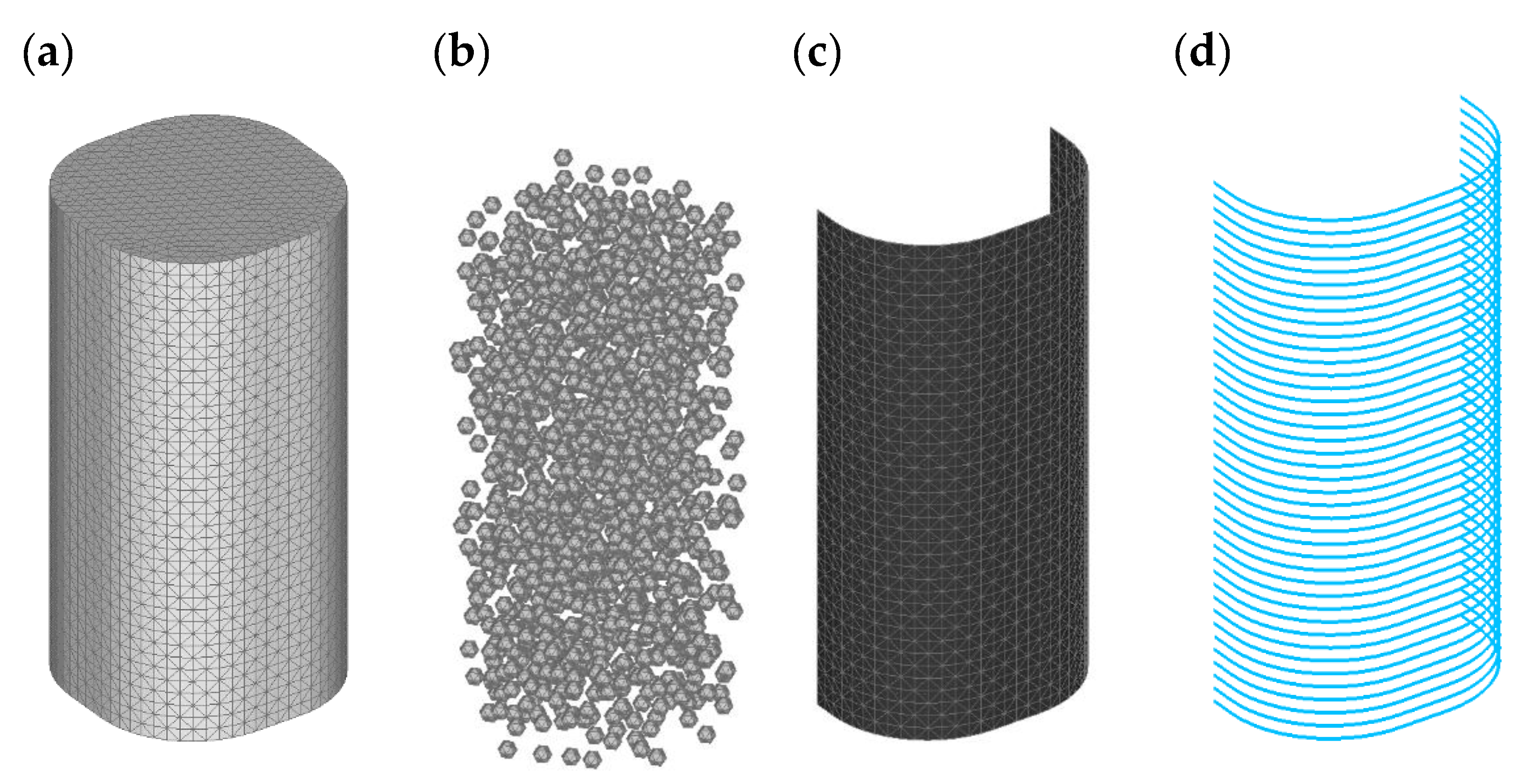
2. Random Aggregate Structure of Concrete

A simple generation procedure that was implemented in Matlab R2013b was used in this study to generate the meso-scale structure of the C30 concrete tested in [7]. Based on proper distance criteria, the coarse aggregate (assumed spherical), with a specific size distribution, was randomly distributed inside the concrete specimen. The coarse aggregate occupies 34% of the total specimen volume, with diameters ranging between 5 and 10 mm.
After evaluating the size distribution of the coarse aggregate (Fuller curve), the procedure reported in [29] was adopted to generate the meso-scale structure of concrete. First, the particle centers were randomly placed inside the specimen. Subsequently, the corresponding spheres, with given diameter, were created from the previous generated centers, and the solids particles were subtracted from the external solid to obtain the two concrete phases (coarse aggregate and mortar matrix). The generated geometries were imported into the FE code MASA [30] and meshed with 3D solid four-node finite elements. In this study, two different concrete compositions were considered in order to generate the FE meso-scale model: (a) composition I (Figure 1a), where only the maximum diameter from the experiments (10 mm) was used to achieve a coarse aggregate volume fraction of 10% and (b) composition II (Figure 1b), where a 30% of the coarse aggregate was obtained with three different diameters (5, 7.5, and 10 mm). The simplified meso-scale structure (Figure 1a) was firstly used in numerical simulations.

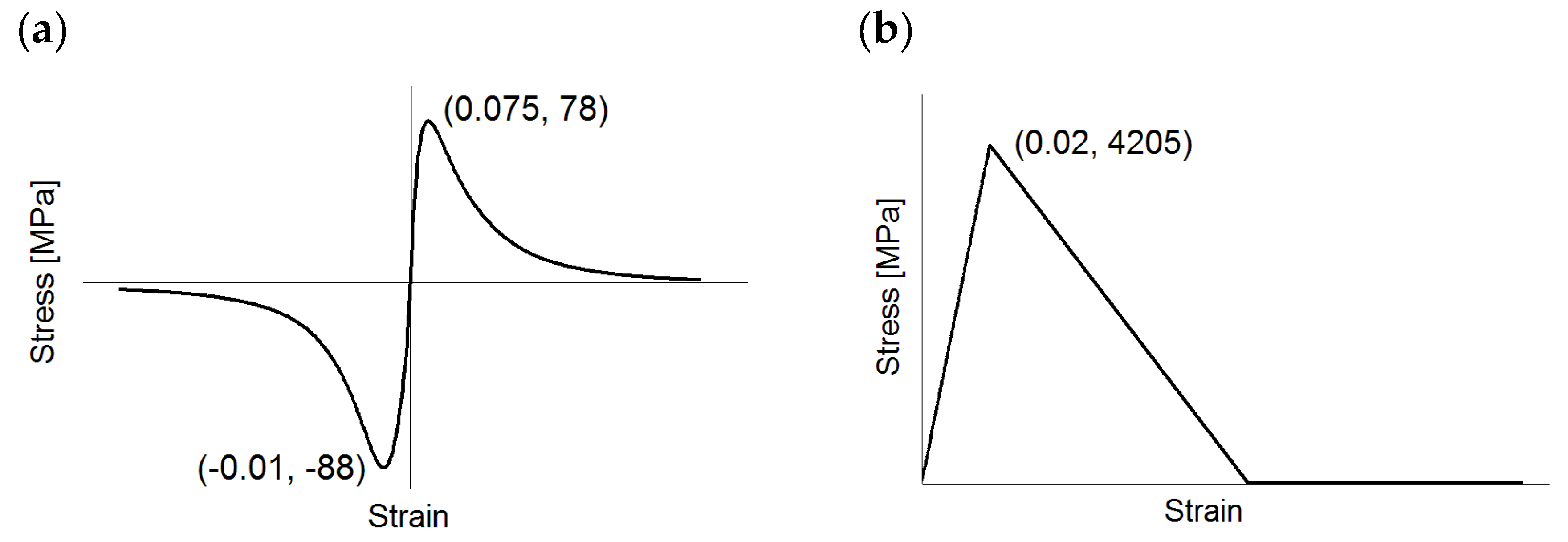
3. Materials and Method

The specimens tested by Wang and Wu [7] present a constant ratio width/height (150/300 mm) and six values of the cross-section corner radius: 0, 15, 30, 45, 60, and 75 mm (Figure 2). Three different configurations were experimentally tested, namely: plain concrete, 1ply CFRP-confined specimens (nominal fiber thickness of 0.165 mm), and 2ply CFRP-confined specimens (nominal fiber thickness of 0.33 mm). Furthermore, two different concrete grades (C30, C50) and two different CFRP were used. In the present study, unconfined and 1ply CFRP-confined specimens that were made of C30 were numerically analyzed at the meso-scale.
The mechanical properties of CFRP (see Table 1) were obtained from the standard coupon test concerning a single-ply specimen [7]. The procedure for evaluating the mechanical properties of the two separate phases is reported in [28]. The tensile strength and the elastic modulus of the CFRP were calculated based on the nominal thickness of the fibers (0.165 mm). The microplane-based non-linear constitutive law [26] was used for the epoxy resin. A proper calibration of the microplane model parameters [28] was carried out based on the experimental results of the coupon test. An elastic-brittle response was assumed for the fibers. Figure 3 shows the constitutive laws that were employed for the two CFRP phases.
Regarding concrete, the constitutive law for mortar (Figure 4) is based on the microplane model [26], while a linear elastic behavior was assumed for the aggregate. The mechanical parameters of the mortar matrix and the aggregate were properly calibrated to correctly simulate the uniaxial compressive behavior of the normal-strength concrete (C30) used in the experiments. The ratio of the elastic moduli of the mortar matrix and the coarse aggregate was set at 1:2.4. The fracture energy of mortar, evaluated with respect to an average element size of 6mm, was assumed to be equal to 50 [J/m2]. The macroscopic elastic and fracture properties of C30 were determined in [28].
Figure 5 shows the finite element discretization of one CFRP-confined specimen (R60). Solid 3D four-node finite elements were used to discretize the concrete phases (Figure 5a,b) and the epoxy resin (Figure 5c), while one-dimensional (1D) truss elements were employed for the carbon fibers (Figure 5d). Perfect connection was assumed between the fibers and the epoxy resin, i.e. no delamination can occur between the two phases.
The load was applied by displacement control in axial specimen direction. The loading and reaction surfaces were confined in the horizontal plane to correctly reproduce the experimental boundary conditions. The crack band method [31] was employed as the regularization technique.

4. Results and Discussion

The results of the numerical simulations are presented in this section for both unconfined and CFRP-confined specimens. First, the results obtained with the simplified meso-scale model (aggregate volumetric fraction = 10%) are discussed. Thereafter, the experimental and numerical results for R15 and R75 are compared with those achieved by employing a more realistic meso-model (30% of coarse aggregate).

4.1. Plain Concrete (10% of Coarse Aggregate)

Figure 6 shows the uni-axial stress-strain curves obtained for plain concrete, through a comparison between numerical and experimental results. As in the experiments, the axial strain was measured over the length of the vertical LVDT used in the tests (200 mm). Good agreement between numerical and experimental results is achieved in all cases, especially for the axial direction. The proposed meso-model can correctly reproduce the typical uniaxial compressive behavior of concrete, as shown in [29]. However, a lower lateral expansion with respect to the experiments is observed in the axial stress-lateral strain curves. This can be partially justified by the absence of the Interfacial Transition Zone (ITZ), which influences the dilatation properties of concrete.
Figure 7 shows the typical failure mode of one confined specimen (R30) in terms of maximum principal strains (crack opening greater than 0.25 mm). Several vertical and inclined cracks are localized in the mid part of the column forming the typical shear band that was observed in the experiments at the end of the test (Figure 7a). Figure 7b shows the internal distribution of damage in mortar (hourglass shape). As shown in [29], the model is able to correctly reproduce the volumetric strain evolution characterized by a transition between volumetric compaction (negative volumetric strains) and volumetric dilatation, as a consequence of damage (see [29]).

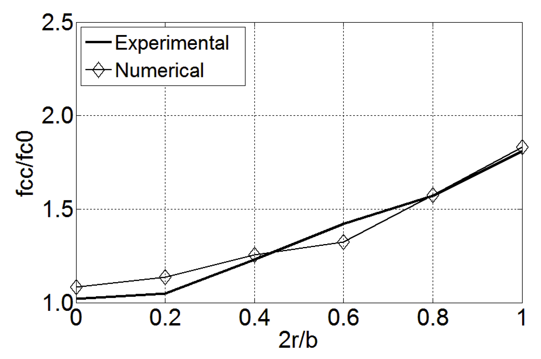
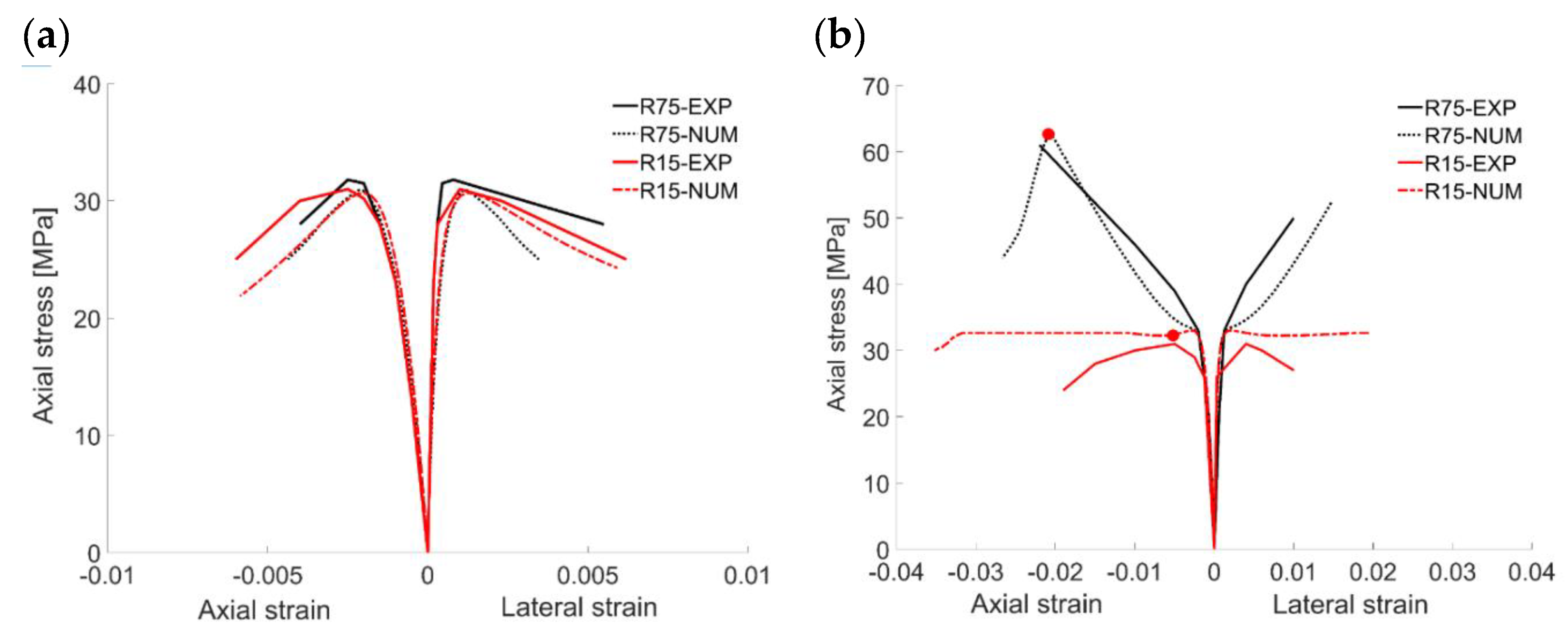
4.2. CFRP-Confined Concrete (10% of Coarse Aggregate)

Figure 8 shows the uni-axial stress-strain curves obtained for the confined specimens. Each graph, related to the corner radius value, shows the numerical and experimental curves. The numerical resuts are in good agreement with the experimental ones, even if larger differences in terms of confined strength are observed for the specimens with sharp corners (R0, R15). The general trend of the numerical curves confirms the experimental evidences, i.e. the confining effect provided by CFRP gradually decreases with the corner radius; however, for R 15 (Figure 8), the model predicts a gradual increase of axial stress until the specimen fails due to tensile rupture of fibers (ε = 0.03).
It is worth mentioning that the experimental confined strengths obtained for R 15 [7] show relatively high scatter (38.8 MPa for batch 1, 31.0 MPa for batch 2, and 30.8 MPa for batch 3). Only one stress-strain curve is reported in [7] and depicted in Figure 8. The curve shows a sudden and premature local rupture of the fibers even before the unconfined peak stress is reached, with a strength value (31.0 MPa) slightly lower than the average strength of the unconfined specimen (31.9 MPa). The confined strength for batch 1 (38.8 MPa) indicates that the CFRP laminate provides some confinement before failure occurs due to tensile rupture of the fibers. Differently, the confined strength for R0 is almost the same for the three bathes and equal to the unconfined one [7], confirming that no-strength gain can be provided by the external jacket.
A suitable criterion should be adopted in order to compare the numerical and experimental results in terms of confined strength. Similarly to the experiments, the simulated specimens failed by tensile rupture of the fibers. However, the ultimate strains that were predicted by the model were in general higher than the experimental ones. The scatter between the curves obtained for the same specimen (usually 3) can be relatively large in terms of ultimate axial strain, as confirmed by experimental studies performed on CFRP-confined columns [32]. This is due to the randomness of the structure of concrete and of CFRP, which cannot be numerically reproduced. Moreover, CFRP can suffer local damage due to relatively small corner radius. For these reasons, the numerical results were evaluated here assuming that the predicted peak stress ( f c , c ) corresponds to the ultimate axial strain from the experiments (red circles).
The results, as summarized in Table 2, confirm the large differences between numerical and experimental results in case of small corner radius.
Figure 9 depicts the relation between the relative strength of the confined columns ( f c , c / f c , 0 ) and relative corner radius ( 2 r / b ) . The numerical results are compared with the test data showing a similar (almost linear) trend.

4.3. CFRP-Confined Concrete (30% of Coarse Aggregate)

The overestimated numerical results that were obtained for the specimens with sharp corners ( R 0 ,   R 15 ) can be partially attributed to a simplified meso-scale composition assumed for concrete. Only 10% of the coarse aggregate was generated by using one diameter that is the maximum from the experiments (10 mm). This simplification, together with the linear elastic behavior assumed for the particles, can lead to an overestimated material response. In reality, a number of factors influence the behavior of CFRP-confined concrete, such as: composition of concrete, non-uniform properties and delamination of CFRP and local damage of CFRP in the case of sharp corners.
The effect of concrete composition is further investigated here by using a more realistic meso-scale model (Figure 1b). The aim was to check whether the model can better capture the interaction between the material heterogeneity and the confining effect provided by CFRP at corner, as mentioned in the introduction. For this reason, the R 15 specimen was analyzed. Furthermore, the cylindrical specimen ( R 75 ) was used to further validate the model results.
Figure 10 shows the obtained stress-strain curves for both unconfined and confined specimens. The model can well reproduce the behavior of unconfined models (Figure 10a), even though a lower lateral expansion is observed with respect to the experiments. In general, the results are comparable to those obtained with the simplified meso-scale model (Figure 6). Differently, the results obtained for the confined specimens (Figure 10b) confirm that a more realistic representation of the material heterogeneity can better capture the behavior of the specimen with sharp corner ( R 15 ). The efficiency of fibers is almost irrelevant in terms of strength gain, while it provides some ductility (horizontal plateau) until global failure occurs due to tensile rupture of the fibers, as shown in Figure 10b. Good agreement is also achieved for the cylindrical specimen, where both peak stress and peak strain are correctly reproduced (Table 3).
Figure 11 and Figure 12 show damage distribution in the confined model ( R 15 ). Similarly to the experiments, the specimens failed by tensile rupture of the FRP wrap. A brittle-type of failure is observed where the rupture of the fibers starts at one corner (Figure 11a), with consequent damage localization in the resin (Figure 11b) near the corner. Significant damage is also observed in concrete (Figure 12). Similar results have been obtained for the cylindrical specimen (Figure 13 and Figure 14).

5. Conclusions

In the present study, the performance of plain and CFRP-confined concrete specimens loaded in uniaxial compression was numerically investigated using the meso-scale modeling approach. The concrete and the CFRP were both modeled as bi-phase composite materials; the former constituted by coarse aggregate and mortar matrix; the latter constituted by epoxy resin and carbon fibers. An interesting aspect of the study is the use of the meso-scale approach to investigate the behavior of CFRP-confined specimens with different cross-section corner radii. Two meso-scale structures for concrete were considered, namely: the concrete composition with 10% of the total coarse aggregate and the more realistic composition with higher volumetric fraction (30%). From the obtained numerical results, the following can be concluded: (1) the adopted meso-scale approach is a suitable tool for the analysis of both unconfined and CFRP-confined specimens; (2) in the case of CFRP-confined specimens, the model is able to capture the influence of the cross-section shape on the confining effect provided by CFRP, which gradually reduces with the decreasing corner radius; (3) the stress-strain curves obtained for 1ply-CFRP are in good agreement with the experimental one, even if for very small corner radius ( R 0 ,   R 15 ) the numerical results show the large differences with the experimental data in the post-peak region; (4) it is shown that the more realistic meso-scale model for concrete can better capture the local damage phenomena at corner, i.e. the interaction between the material heterogenity and CFRP is more realistic; and, (5) similarly to the experiments, the failure mode of the confined specimens is governed by tensile rupture of the fibers near the corner area. The interaction mechanisms between concrete and CFRP, togheter with shape of the cross-section, strongly influence the performance of the confined specimens; (6) Further studies will be carried out by the authors to investigate the effect of the following influential parameters: type of composite (fibers, matrix), jacket thickness.

Author Contributions

S.G. and J.O. developed conception of the study and defined the methodology; S.G. developed the 3D meso-scale models and perfomed the numerical analysis. S.G. wrote the first draft of the manuscript; J.O. wrote sections of the manuscript. All authors contributed to the manuscript revision, read and approved the submitted version. All authors have read and agreed to the published version of the manuscript.

Funding

This research received no external funding.

Conflicts of Interest

The authors declare no confict of interest.

References

  1. Chalioris, C.E.; Kosmidou, P.-M.K.; Papadopoulos, N.A. Investigation of a new strengthening technique for RC deep beams using carbon FRP ropes as transverse reinforcements. Fibers 2018, 6, 52. [Google Scholar] [CrossRef] [Green Version]
  2. Bocciarelli, M.; Gambarelli, S.; Nisticò, N.; Pisani, M.A.; Poggi, C. Shear failure of RC elements strengthened with steel profiles and CFRP wraps. Compos. Part B 2014, 67, 9–21. [Google Scholar] [CrossRef]
  3. Chalioris, C.E.; Zapris, A.G.; Karayannis, C.G. U-jacketing applications of fiber-reinforced polymers in reinforced concrete T-beams against shear—Tests and design. Fibers 2020, 8, 13. [Google Scholar] [CrossRef] [Green Version]
  4. Wang, X.; Petru, M.; Ai, J.; Ou, S. Parametric Study of Flexural Strengthening of Concrete Beams with Prestressed Hybrid Reinforced Polymer. Materials 2019, 12, 3790. [Google Scholar] [CrossRef] [PubMed] [Green Version]
  5. Attari, N.; Amziane, S.; Chemrouk, M. Flexural strengthening of concrete beams using CFRP, GFRP and hybrid FRP sheets. Constr. Build. Mater. 2012, 37, 746–757. [Google Scholar] [CrossRef]
  6. Lewangamage, C.S.; Rankoth, C.K.; Jayasinghe, M.T.R. A Study on Reinforced Concrete Columns Partially Confined with Carbon Fibre Reinforced Polymer (CFRP). Engineer 2017, 4, 41–50. [Google Scholar] [CrossRef]
  7. Wang, L.-M.; Wu, Y.-F. Effects of corner radius on the performance of CFRP-confined square concrete columns. Test. Eng. Struct. 2008, 30, 493–505. [Google Scholar] [CrossRef]
  8. Lam, L.; Teng, J.G. Design-oriented stress-strain model for FRP-confined concrete. Constr. Build. Mater. 2003, 17, 471–489. [Google Scholar] [CrossRef]
  9. Realfonzo, R.; Napoli, A. Confining concrete members with FRP systems: Predictive vs design strain models. Compos. Struct. 2013, 104, 304–319. [Google Scholar] [CrossRef]
  10. Girgin, Z.C.; Girgin, K. A Design-Oriented Combined Model (7 MPa to 190 MPa) for FRP-Confined Circular Short Columns. Polymers 2015, 7, 1905–1917. [Google Scholar] [CrossRef]
  11. Jiang, T.; Teng, J.G. Analysis-oriented stress-strain models for FRP-confined concrete. Eng. Struct. 2007, 29, 2968–2986. [Google Scholar] [CrossRef] [Green Version]
  12. Lim, J.; Ozbakkaloglu, T. Unified Stress-Strain Model for FRP and Actively Confined Normal-Strength and High-Strength Concrete. J. Compos. Constr. 2015, 19, 04014072. [Google Scholar] [CrossRef]
  13. Cascardi, A.; Micelli, F.; Aiello, M.A. Unified model for hollow columns externally confined by FRP. Eng. Struct. 2016, 111, 119–130. [Google Scholar] [CrossRef]
  14. Rousakis, T.C.; Karabinis, A.I.; Kiousisb, P.D. FRP-confined concrete members: Axial compression experiments and plasticity modeling. Eng. Struct. 2007, 29, 1343–1353. [Google Scholar] [CrossRef]
  15. Karabinis, A.I.; Kiousis, P.D. Effects of confinement on concrete columns: Plasticity approach. ASCE J. Struct. Eng. 1994, 120, 2747–2767. [Google Scholar] [CrossRef]
  16. Karabinis, A.I.; Kiousis, P.D. Strength and ductility of rectangular concrete columns—A plasticity approach. ASCE J. Struct. Eng. 1996, 122, 267–274. [Google Scholar] [CrossRef]
  17. Rousakis, T.C.; Karabinis, A.I.; Kiousis, P.D.; Tepfers, R. Analytical modelling of plastic behavior of uniformly FRP confined concrete members. Compos. Part B 2008, 39, 1104–1113. [Google Scholar] [CrossRef]
  18. Karabinis, A.I.; Rousakis, T.C.; Manolitsi, G. 3D Finite Element Analysis of Substandard Columns Strengthened by Fiber Reinforced Polymer Sheets. ASCE J. Compos. Constr. 2008, 12, 531–540. [Google Scholar] [CrossRef]
  19. Yu, T.; Teng, J.G.; Wong, Y.L.; Dong, S.L. Finite element modeling of confined concrete-II: Plastic-damage model. Eng. Struct. 2010, 32, 680–691. [Google Scholar] [CrossRef]
  20. Wu, Y.F. Development of constitutive models for FRP-confined concrete structures. Compos. Part B-Eng. 2015, 1, 90. [Google Scholar]
  21. Lo, S.H.; Kwan, A.K.H.; Ouyang, Y.; Ho, J.C.M. Finite element analysis of axially loaded FRP-confined rectangular concrete columns. Eng. Struct. 2015, 100, 253–263. [Google Scholar] [CrossRef]
  22. Dong, C.X.; Kwan, A.K.H.; Ho, J.C.M. A constitutive model for predicting the lateral strain of confined concrete. Eng. Struct. 2015, 91, 155–166. [Google Scholar] [CrossRef]
  23. Menétrey, P.; Willam, K.J. Triaxial failure criterion for concrete and its generalization. ACI Struct. J. 1996, 92, 589–601. [Google Scholar]
  24. Hany, N.F.; Hantouche, E.G.; Harajli, M.H. Finite element modeling of FRP-confined concrete using modified concrete damaged plasticity. Eng. Struct. 2016, 125, 1–14. [Google Scholar] [CrossRef]
  25. Ceccato, C.; Pellegrino, C.; Cusatis, G. Simulation of concrete failure and fiber reinforced polymer fracture in confined columns with different cross sectional shape. Int. J. Solids Struct. 2017, 108, 216–229. [Google Scholar] [CrossRef]
  26. Ožbolt, J.; Li, Y.-J.; Kožar, I. Microplane model for concrete with relaxed kinematic constraint. Int. J. Solids Struct. 2001, 38, 2683–2711. [Google Scholar] [CrossRef]
  27. Gambarelli, S.; Nisticò, N.; Ožbolt, J. Microplane Model for Concrete: Part II—Applications on CFRP Confined Concrete Elements. In Applied Mechanics and Materials, Advances in Civil and Infrastructure Engineering II, Chapter II; Trans. Tech. Publications Ltd.: Zürich, Switzerland, 2016; Volume 847, pp. 106–120. [Google Scholar]
  28. Gambarelli, S.; Nisticò, N.; Ožbolt, J. Numerical analysis of compressed concrete columns confined with CFRP: Microplane-based approach. Compos. Part B 2014, 67, 303–312. [Google Scholar] [CrossRef]
  29. Gambarelli, S.; Nisticò, N.; Ožbolt, J. Mesoscale model for concrete: Microplane-based approach. In Proceedings of the 9th International Conference on Fracture Mechanics of Concrete and Concrete Structures (IA-FraMCoS), Berkeley, CA, USA, 22–25 May 2016. [Google Scholar]
  30. Ožbolt, J. MASA—Macroscopic Space Analysis; Internal Report; Institute für Werkstoffe im Bauwesen, Universität Stuttgart: Stuttgart, Germany, 1998. [Google Scholar]
  31. Bažant, Z.P.; Oh, B.H. Crack band theory for fracture of concrete. Mater. Struct. RILEM 1983, 16, 155–177. [Google Scholar] [CrossRef] [Green Version]
  32. Karabinis, A.I.; Rousakis, T.C. Carbon FRP confined concrete elements under axial load. In Proceedings of the International Conference on FRP Composites in Civil Engineering, Hong Kong, China, 12–15 December 2001; Teng, J.G., Ed.; 2001; pp. 309–316. [Google Scholar]
Figure 1. Concrete meso-structure: (a) 10% of coarse aggregate with one diameter (D = 10 mm) and (b) 30% of coarse aggregate with three diameters (10, 7.5 , 5 mm).
Fibers 08 00038 g001
Figure 2. Cross-section corner radii of the columns.
Fibers 08 00038 g002
Figure 3. Constitutive law for: (a) Epoxy resin and (b) fibers (adapted from [28]).
Fibers 08 00038 g003
Figure 4. Constitutive law for mortar matrix [29].
Fibers 08 00038 g004
Figure 5. FE model for R60: (a,b) concrete (c,d) CFRP.
Fibers 08 00038 g005
Figure 6. Plain concrete: uniaxial stress-strain curves: (a) R75, (b) R60, (c) R45, (d) R30, (e) R15, (f) R0.
Fibers 08 00038 g006
Figure 7. (a) Typical failure mode of R30 and (b) Internal damage distribution in mortar.
Fibers 08 00038 g007
Figure 8. CFRP-confined specimens: uniaxial stress-strain curves: (a) R75, (b) R60, (c) R45, (d) R30, (e) R15, (f) R0.
Fibers 08 00038 g008aFibers 08 00038 g008b
Figure 9. Variation of the strength of 1ply CFRP-columns with the corner radius (normalized values).
Fibers 08 00038 g009
Figure 10. Stress-strain curves for: (a) unconfined specimens (R15, R75) and (b) 1ply CFRP-confined specimens (R15, R75).
Fibers 08 00038 g010
Figure 11. Typical failure mode R15: (a) tensile rupture of fibers and (b) damage inside the resin.
Fibers 08 00038 g011
Figure 12. Typical failure mode R15: (a) concrete damage and (b) internal distribution of damage in mortar (maximum principal strains).
Fibers 08 00038 g012
Figure 13. Typical failure mode R75: (a) tensile rupture of fibers and (b) damage inside the resin.
Fibers 08 00038 g013
Figure 14. Typical failure mode R75: (a) concrete damage and (b) internal distribution of damage in mortar (maximum principal strains).
Fibers 08 00038 g014
Table 1. Mechanical properties of concrete and Carbon Fibre Reinforced Polymer (CFRP).
Material PropertiesConcreteCFRP
MortarAggregateCarbon FibersEpoxy Resin
E [MPa]38,00090,000211,0003000
ν 0.20.2-0.25
f c [MPa]28--88.0
f t [MPa]2.8-420578.0
G F [J/m2]50---
Table 2. Percentage error with respect to f c , c   [MPa] from the experiments (1ply).
1ply CFRPR75R60R45R30R15R0
fc,c_num [MPa]58.650.3942.3340.1536.3734.67
fc,c_exp [MPa]61.251.742.138.83232
error [%]4.252.530.543.4913.678.33
Table 3. Percentage error with respect to fcc [MPa] from the experiments (R15, R75).
1ply CFRPR15R75
fc,c_num [MPa]62.8732.4
fc,c_exp [MPa]61.232
error [%]0.030.01

