Abstract
The integration of optical and wireless networks increases mobility and capacity and decreases costs in access networks. Fibre optic communication can be considered optical communication that combines the methodologies of two communications, and it may be utilised in systems of wired and wireless communication. The solution for many problems is radio over fibre (RoF) because it can control many base stations (BS) that are connected to a central station (CS) with an optical fibre. The received RoF signal head for in a low quality; thus, many factors will result in some problems such as a high bit error rate (BER) and low Q-factor values, and the receiver might not be operating in a high data rate network. Wavelength division multiplexing (WDM) network can offer a solution to these problems where the transmission of different signals can be done with a single-mode fibre. BER should be reduced to assured values, and the Q-factor must be increased. The investigation of WDM-RoF with different lengths of fibre at various channel spacing will be simulated using Optisystem software, and the RoF’s receiver performance is measured and analyzed depending on the acquired BER, the value of the Q-factor, and the height of the opening of the eye diagram. The degradation factors effect such as attenuation and dispersion are significantly limited with the addition of an EDFA amplifier to a Single Mode Fibre (SMF).
1. Introduction
The fast evolution of Internet traffic and emerging applications can be considered a significant driver for high-capacity and cost-effective optical fibre transmission technologies. The technique of the information transmitting between two positions is a fibre optic communication, which is completed by sending light within the optical fibre [1]. This communication system can be used for long distance applications that’s needed a total transmission capacity and increasing cost recovering. Optical transmission systems are popular for maintaining low power for short-to-medium-range wireless communications. However, for other applications where transmission distance is large, high power is required. In an optical fibre, various nonlinear effects begin to appear as the optical power level increases [2].
Radio over fibre (RoF) is an analogue optical link transmitting modulated RF signals. It assists in transmitting the RF signal downlink and uplink to and from the central station (CS) to the base station (BS). The characteristics of great capacity, high speed with small losses are considered at the beginning for the RoF systems, where the main advantage of Rof systems is the mobile communication adaptability and flexibility to associate with the growth movement of the forthcoming 5G mobile communication in addition to the request services for gigabit size [3].
The wavelength division multiplexing (WDM) technique is used in optical communication for the multiplexing sum of optical carrier signals that have various wavelengths within a single optical fibre. These signals have different laser light wavelengths to carry different signals. They can realize higher data rate, larger capacities, and enhanced flexibility with a comparatively low cost. This upgrade can be easily achieved for these systems, in addition to the bidirectional transmission advantage over a length of the single fibre at both transmitter and receiver [4].
Using WDM as an alternative to the FDM (frequency-division multiplexing) technique was suggested in 1970 by DeLange. The characteristics of implementation any modulation scheme within WDM is realized for any wavelength; however, with the condition of the signal spectral, width must not exceed the limit of the using channel spacing. The total capacity per fibre optic within this WDM technique is assumed by N × R, where R represents the channel bit rate and is supposed to be similar for all channels [5].
The WDM bands have an approximation wavelength range value has not been standardized thus far. These bands, like O-band, S-band, and C-band, have a range different from another; for example, the range of 1260 nm to 1360 nm for O-band corresponds to a bandwidth of 14 THz, while the 1460 nm to 1625 nm range is for a grouping of S-band and C-band and corresponds to 15 THz of bandwidth [6]. The total available bandwidth per fibre optic in an individual O-band, S-band, and C-band is around 30 THz of the low-loss regions of a standard G.652 single-mode fibre [7].
This paper focuses on the transmission of data streams over a range of optical fibre lengths using the WDM scheme. The channel spacing was maintained at 0.4 nm, and the input power was fixed, so that the WDM-RoF network execution can be analyzed.
2. Materials and Methods
2.1. WDM
WDM is an important feature in the expansion of optical communications. WDM has provided more flexibility to the system and simplified the network design. It helps with the enhancement of the system’s capacity by sending multiple wavelengths over a single fibre [8]. A considerable increase in the data rate can be offered by WDM systems that are passed over a single fibre using multiple wavelengths, where a separate channel is carried at each wavelength. In WDM, the optical spectrum is divided into smaller channels; each can be used for transmitting and receiving data simultaneously [9].
For the WDM system, each wavelength can be preserved as a discrete channel on which different data can be carried. A WDM multiplexer can be considered a passive device where light signals are combined with different wavelengths in a single fibre. The use of WDM for RoF signal distribution has gained importance in recent times. WDM enables the effective exploitation for the fibre bandwidth. The optical filter selection and wavelength stability limitations of semiconductor lasers, as well as the minimum channel spacing for commercial WDM, is approximately 50 GHz. This channel spacing can be reduced to 50 GHz or made equal to 25 GHz with a possibility of using hundreds of channels [10].
The optical WDM network is illustrated in Figure 1, in which a substitution of the wavelength of frequency and a separated wavelength λi are transmitted by each transmitter to different receivers [11]. WDM has the ability to transmit different frequencies without any interference in radio broadcasting [12]. Two types of WDM systems are dense wavelength division multiplexing and coarse wavelength division multiplexing.
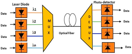
Figure 1.
Wavelength division multiplexing (WDM) configuration.
In the WDM technique, N optical wavelength numbers can be used as a data carrier, and these wavelengths can be combined with an optical fibre utilising WDM multiplexer, while at the receiver, the separation of these wavelengths as individual channels will be done by using a WDM demultiplexer. Each optical wavelength is different and typical; the gap between wavelengths controls the channel spacing to avoid the overlapping, which has happened in the optical carriers [13].
Subcarrier Multiplexing (SCM) can be considered a complement of multiplexing techniques that can be utilised in optical systems for increasing the efficiency of bandwidth application. In an RoF system with SCM technique, multiple radio frequency RF signals multiplex in the frequency domain and are then transmitted at a single wavelength. SCM can be combined with WDM to provide a more flexible technique for optical transmission at high speed with high optical bandwidth efficiency in addition to high dispersion tolerance. This combination is more sensitive to noise effects; however, there is a disadvantage, as represented by the limitation of the maximum subcarrier frequencies and data rates.
2.2. RoF
The RoF system is practically well-matched with the technology of WDM, which gives a huge number of the essential BS for covering a wireless service area in arrangements of the Pico- or Femto- cell [14].
The demand to have broadband capacity, which applies a pressure on the wireless communication systems for increasing the coverage area and the capacity of the transmission [15].
RoF is an appropriate system because it consumes less power and costs less. This is because the RoF system lets the electrical signal modulate the optical source. Then, the optical signal is propagated through the optical fibre to a remote station. If the RF signal is modulated directly to the optical link, the power consumption will be dropped while the antenna side has carriers with high radio frequency. The cost reduction in RoF technology can be demonstrated in two stations: the first is CS, which provides resources that may be shared by a set of BS; the second is BS, which can only execute simple tasks. Furthermore, the size of BS is smaller, and it costs less.
The range of GHz frequency requires extra bandwidth, which gives additional capacity for carrying data. For a wireless data transmission, further losses are encountered in RoF systems, hence no long distance transmission can be performed. Instead, low-frequency signals can be used for long distances which encounters fewer losses. Therefore, there is a need for a waveguide for carrying these signals.
In RoF, the CS is connected with many BS with optical fibres. BS functions only to convert an optical signal into a wireless signal and vice versa, whereas CS executes all processes of modulation, demodulation, routing, and coding. The RoF system distributes the RF signal using a high linear optic link between CS and BS.
The demand for increasing the capacity and the bandwidth of wireless system, the WDM technique has been employed in RoF systems (WDM-RoF). A wireless network based on RoF technologies is a practical solution. It acts as a back-end technology for the transportation of microwaves and millimetre waves [16].
Integration of WDM into RoF leads to a significant increase in the coverage area and the overall capacity of the current optical network and offers the benefits of high data rate and increased mobility. A WDM-RoF system is proposed for signal demodulation. This has prevented the need to design and install two separate networks.
The universal Internet traffic is increasing at a massive pace and is estimated to keep increasing over the next few years. To support this growth, a future-proof network needs to be designed. This network needs to offer large bandwidth and high data rate in a cost-effective way. If this network can combine wireless and wired facilities together, then, along with high data rate, increased mobility can be achieved [17]. RoF is a technique that combines both wired (optical) and wireless (microwave) networks. An RoF network involves the transmission of RFs over an optical fibre link to support numerous wireless applications.
A solution has been proposed by many researchers. Singh et al. [3] proposed a WDM–RoF system transmitting a 1 Gbps downlink and uplink information stream over a length of 25 km with an effectively–factor. Pradeep et al. [5] proposed architecture for wired as well as wireless systems that was capable of delivering a 2.5 Gbps uplink signal. Won et al. [11] demonstrated the synchronous transmission of a 1.25 Gbps wired and wireless information stream over a WDM–RoF access system. Arief et al. [17] proposed a blend of SCM and WDM models to ensure vast transmission capacity and a high information rate in cellular communication, particularly between CS and BS.
Abdel Hakeim M. Husein (2014) [18] investigated spectrum sliced dense wavelength division multiplexed passive optical network (SS-DWDM–PON) as a solution for power active and cost efficient in optical access network. An SS-DWDM system with high speed can be achieved with 32 channels a data rate can be reached of up to 3 Gb/s non-return-to-zero (NRZ) and return-to-zero (RZ) using a broadband amplified spontaneous emission (ASE) source. This was demonstrated in a 40 km optical fiber link with bit error rate (BER) < 10−12.
Fady et al. (2017) [19] proposed and investigated a 10 Gbit/s symmetric bidirectional WDM-PON system with centralized direct and lightwave detection. The transmission of the differential phase-shift keying (DPSK) modulated signal over Single Mode Fibre (SMF) with a length of 25-km can be considered for downstream. While, for upstream link the DPSK modulated signal would be demodulated using RSOA (Reflective Semiconductor Optical Amplifier) that exit at the optical network unit (ONU) side. The corresponding results for a WDM-PON with symmetric 10 Gbit/s were achieved in the proposed design with a small effect of dispersion. The results indicate that the BER curve went down from BER = 1 × 10⁻¹³ at Pu = −13.89 dBm to BER = 1 × 10⁻¹⁶ at Pu = −13.835 dBm in the downstream signal for the SMF length of 25 km.
Optical amplifiers and local networks might make major contributions in the long term. Even optical signals can be transmitted without amplifiers for a long distance. Many techniques can be used for optical amplification, such as regeneration techniques that provide support for powering up the signal and ensuring total data transparency. Another technique is regeneration and reshaping amplification, in which an optical signal can be converted into electrical signals and then be utilised for modulating a laser. There are also regeneration, reshaping, and relocking techniques, which can transform the data stream within an electronic signal. After that, the retransmission of optical signal for amplifying the signal [9]. In this technique, the noise can be removed greatly over the reshaping process. Typically, reshaping tasks are conducted on digital signals; however, in some cases, they are conducted on analog signals. Relocking cannot be done with an analog modulated signal.
3. Description of WDM-RoF System
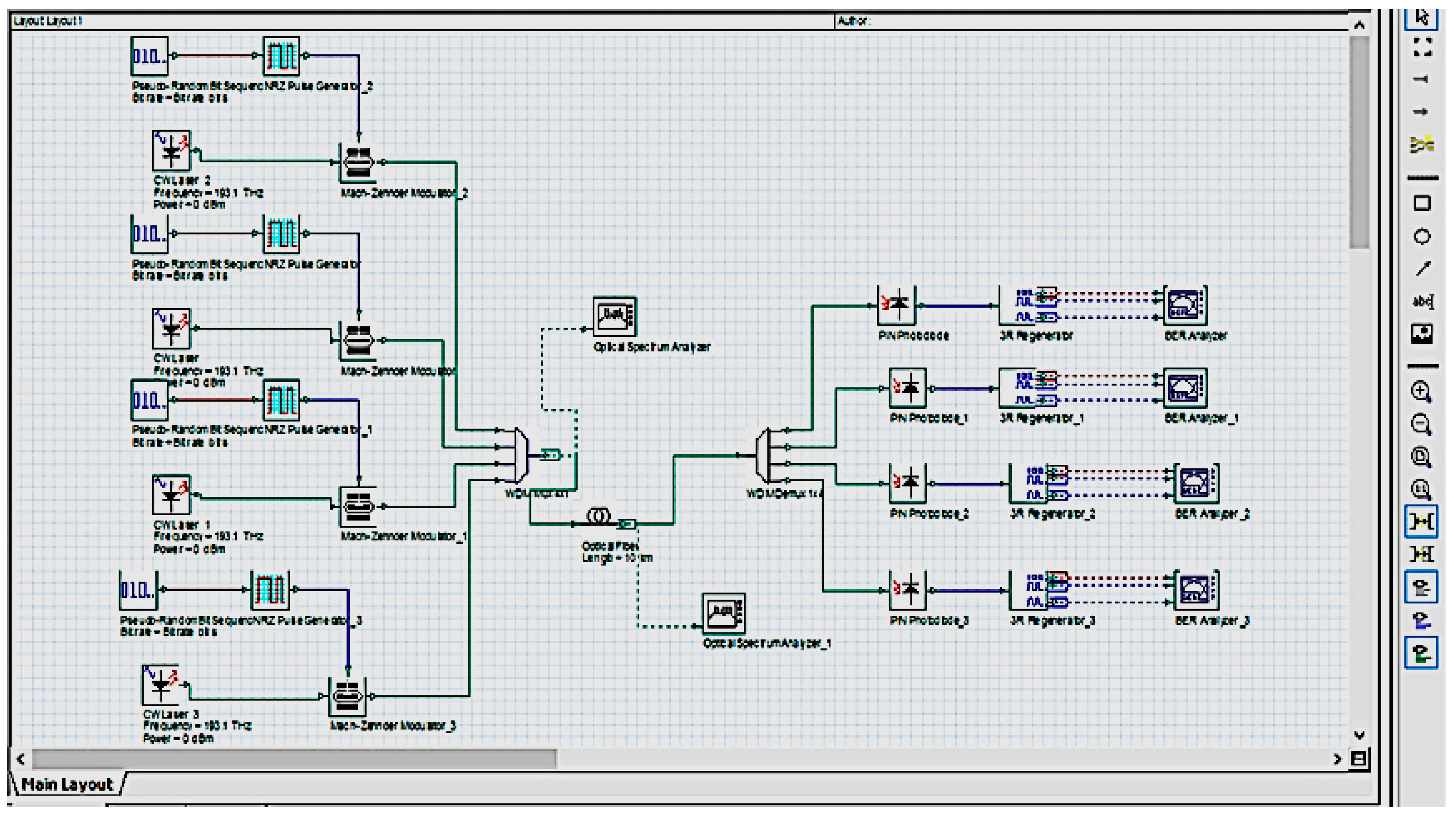
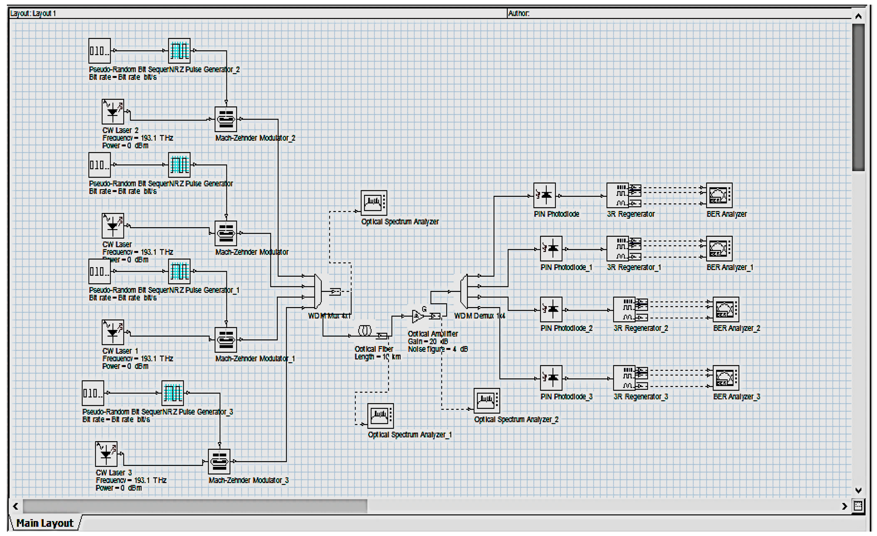
The suggested system consists of four RF signals transmitted over single-mode optical fibre at different distances (5, 10, 20, 50, and 60 km) and received by four remote stations. RoF network with optical communication can be simulated and implemented using Optisystem, a powerful and inventive software design tool that allows users to design, test, and simulate virtually each optical type of link positioned in the transmission layer of the broad spectrum of the optical networks.
The block diagram of the proposed WDM-RoF system is shown in Figure 2. The transmitter consists of channels, and each channel has its own operating wavelength. Channel 1 is 1552.50 nm, with a linewidth of 10 MHz, and so on. As a result, a wavelength spacing equal to 0.4 nm between subsequent channels is maintained for low and smooth transmission. Because the separation is narrow, it helps to support big client numbers and to accomplish a high rate. Each channel has an input power to be changed from −15 dBm to 15 dBm with a step of 5dBm. The WDM multiplexer that has a bandwidth of 10 GHz can combine the signal that comes from the input channel and then transmit it over the optical fibre. The optical fibre length varies from 5 km to 60 km. In optical communication links, Erbium Doped Fiber Amplifiers (EDFAs) are used for enhancing the signal power to all channels simultaneously.
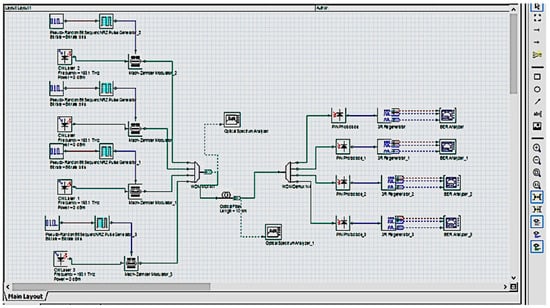
Figure 2.
The proposed WDM-radio over fibre (RoF) system.
The proposed WDM multiplexer of 10 GHz bandwidth has a four-signal combination, each from one input channel, which it transmits over an optical fibre link that operates in the wavelength window of 1550 nm and requests for dispersion management.
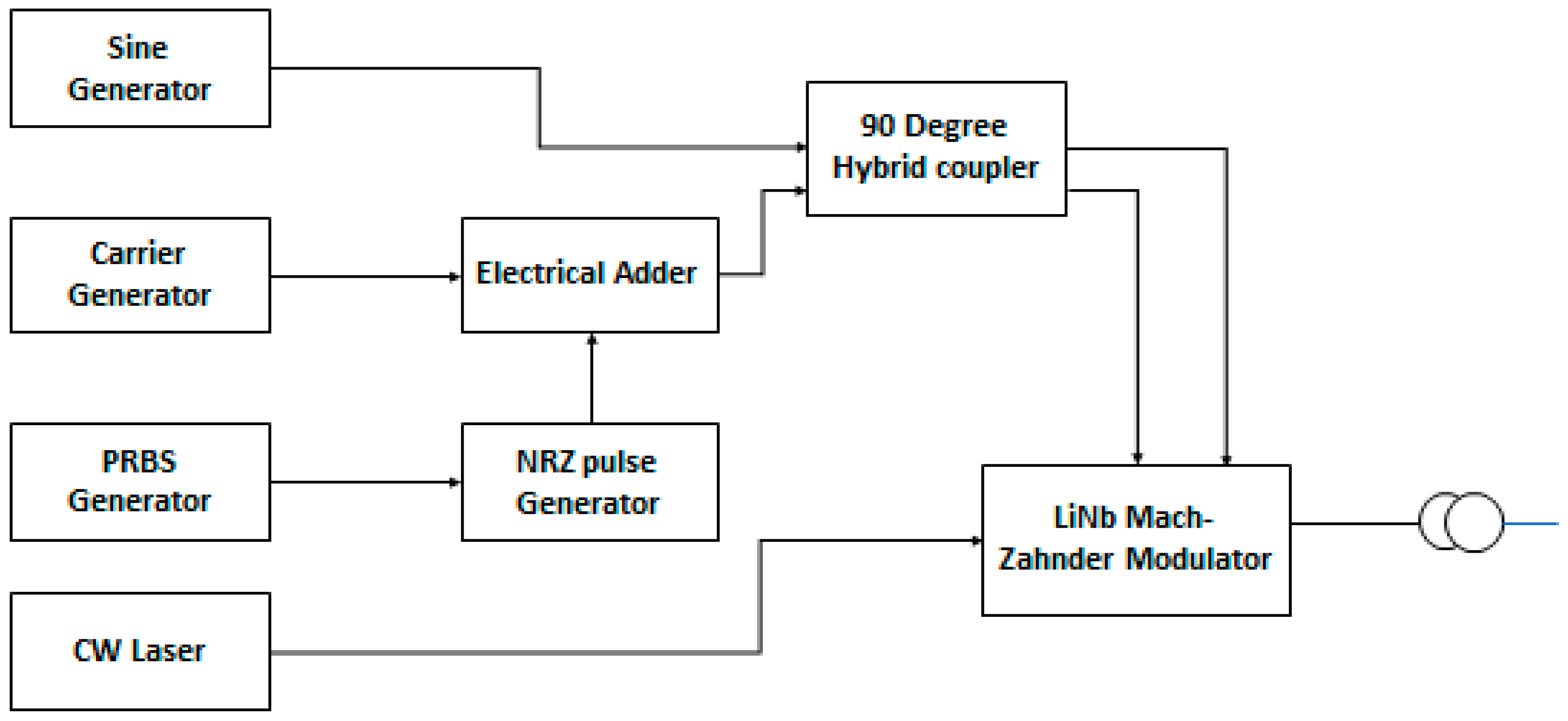
At the transmitter, the binary data supplied by the pseudo-random bit sequence (PRBS) is converted into non return to zero (NRZ) electrical pulses to generate a baseband signal. The information rate for the re-enactment of both the downlink and uplink signals is set to 1 Gbps. The carrier frequency of the electrical amplitude modulator is 1.7 GHz and can be used to convert the frequency of the baseband signal to the RF clock frequency.
The RF signal is applied to the 90° hybrid coupler after the SCM carrier generator, as shown in Figure 3. Furthermore, the outputs of the hybrid coupler are connected to the dual port, dual drive, Lithium Niobate (LiNb), Mach-Zender modulator (MZM). The MZM is used for the transmission of microwave signals into optical signals. This MZM has four ports, out of which three are used as an input port and one is used as an output port. Subsequently, port 1 of MZM is driven by the amplitude modulator, and port 2 is driven by a 1 Gbps baseband signal. The optical signal obtained at the output port of MZM is further transmitted over the optical fibre link.
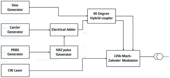
Figure 3.
WDM transmitter.
Then, the optical modulated signal is passed through an SMF channel. This optical link model utilises an SMF, which confirms a good quality level through the transport of signals. The attenuation factor value can be chosen with 0.2 dB/ km, and the distance changes from 5 km to 600 km.
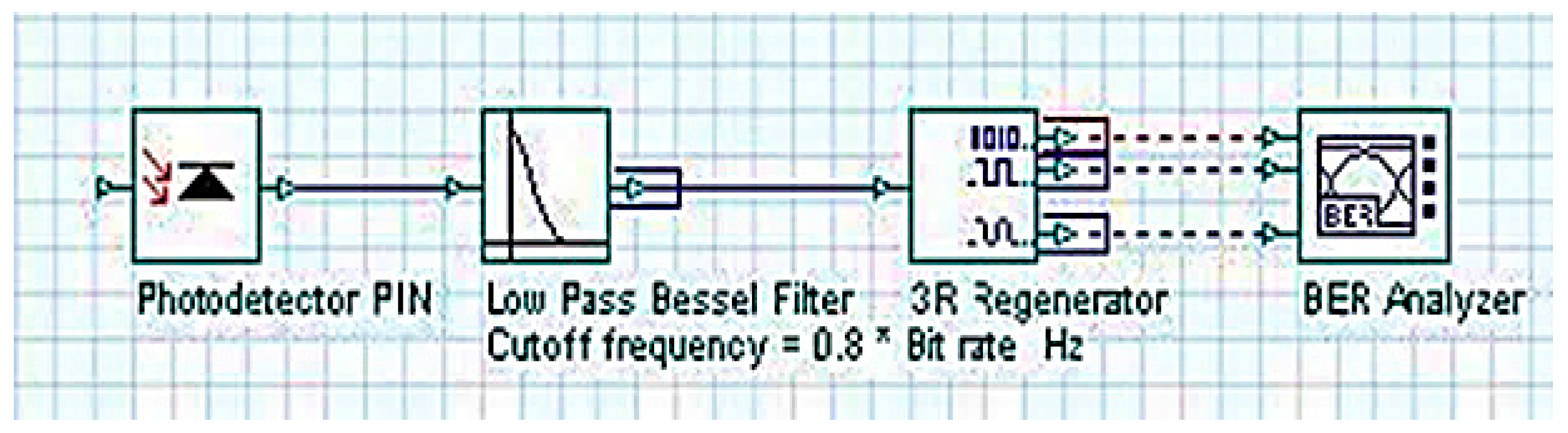
Figure 4 shows a receiver with a positive intrinsic negative (PIN) photodetector, low-pass Bessel electrical filter with 16 GHz cut-off frequency, and BER analyzer. The thermal noise of the PIN detector is not taken into account.
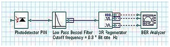
Figure 4.
Receiver layout.
In the figure, the optical modulated signal sent through the fibre is directly detected on the PIN photodiode with a suitable sensitivity. The photocurrent is a replica of the modulated RF signal applied externally by means of the MZM modulator at the transmitter. This PIN photodiode converts the optical signal to an electrical signal, which is then amplified through an electrical amplifier for making up the power loss owing to the attenuation in the fibre. A gain of 20 dB confirms that all distorted signals that are attenuated through transmission by fibre channels may be recovered at the receiver.
In the electrical section of the receiver, after the down conversion of RF from an optical signal and the amplification process by the repeater, a fork is used to duplicate the input signal and develop four output signals. A low-bass Bessel filter (LPF) is used to separate interesting individual RF signals from other RF signals, and then a quadrature demodulator is used to demodulate the signal. The LPF selection is intended to improve the system performance by controlling the nonlinear effects of crosstalk.
The main descriptions of the components in the proposed network are as follows:
- Pseudo random number generator (PRPS): a bit sequence is generated here, based on various operating modes. The design of such bits is related to the random data characteristics.
- NRZ coding: generates a pulse according to the PRBS sequence.
- Laser: generates a continuous wave optical signal.
- Optical modulator: this modulator depends on the effect of electro-optic principle that the external voltage is applied to change the refractive index and as a result the intensity modulation is occured.
- PIN photodiode: the optical signal obtained from the fibre is filtered and converted to an electrical signal.
- The performance of the RoF receiver can be measured by investigating the eye diagram after a simulated design has been prepared. The eye diagram analyzer uses a modulated signal with multiple traces to create an eye diagram. The produced eye diagram can be considered an oscilloscope display, where the diagram corresponds to minimal signal distortion owing to intersymbol interference in addition to the appearing noise in the system. Eye pattern measurements are completed based on the time domain, and the waveform distortion effect may appear in the regular BER screen of test equipment. The time interval and noise margin are a part of the information that can be obtained from the eye pattern display.
4. Results and Discussion
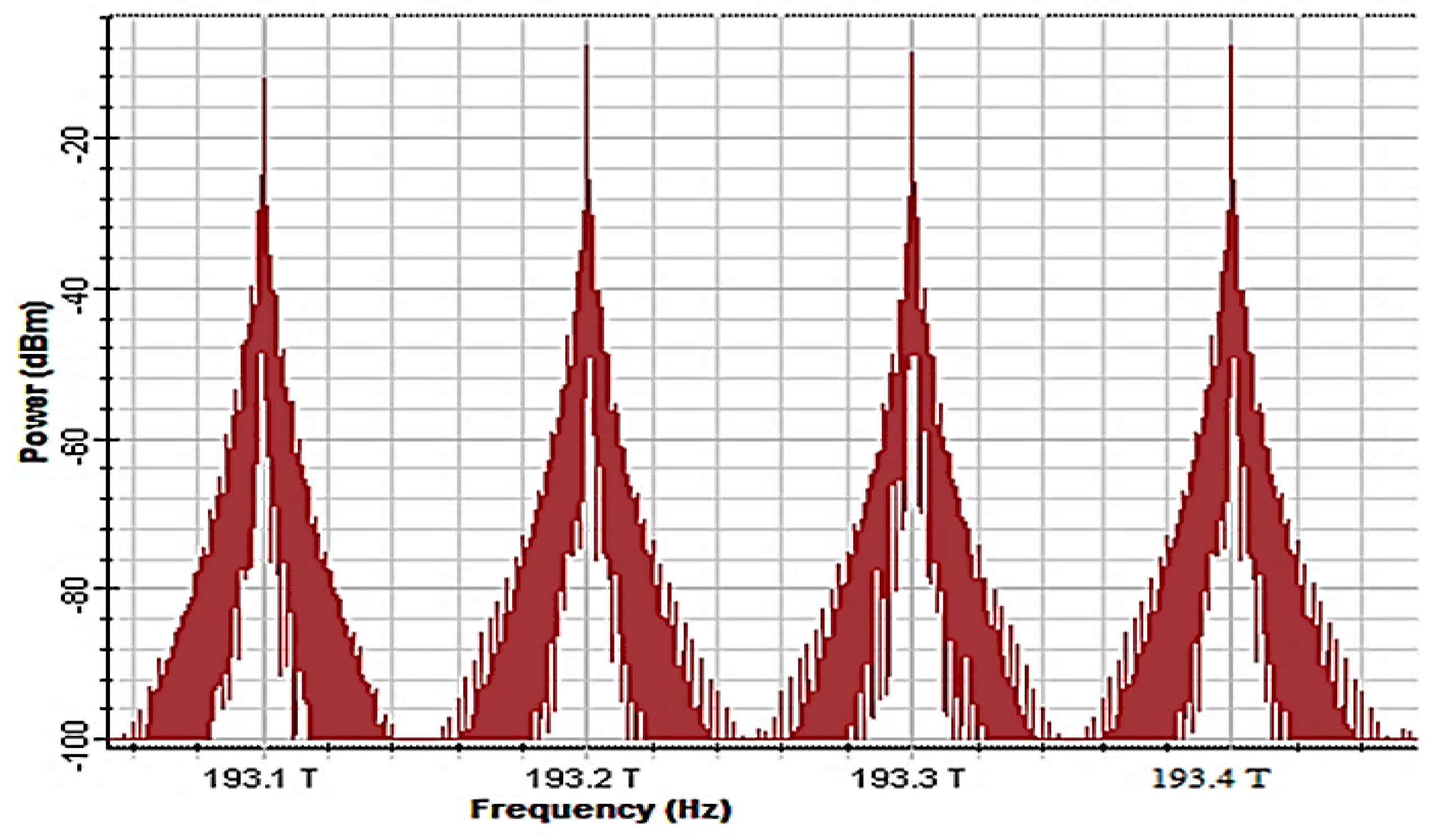
The proposed WDM-RoF network was positively simulated and analyzed using Optisystem 13, a commercial optical system simulator. Figure 5 shows the optical spectrum after being multiplexed by the WDM multiplexer. The spectrum was observed using an optical spectrum analyzer at the output of the WDM multiplexer.
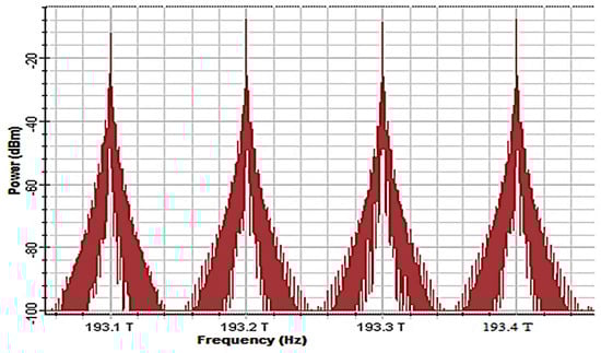
Figure 5.
Optical spectrum multiplexed by WDM.
Single parameter optimisation (SPO) can benefit the simulation a lot. SPO assistances the simulator for optimizing all parameters to allow the access to the results of the simulation. Thus, the optimization of the length of EDFA and a maximum gain can be obtained with the software of optimization tools. Moreover, the attenuation can be measured for getting the Q-factor and BER with a minimum values from the length of fibre optimization.
The simulation was run immediately after the connection of all components was completed and SPO was initialized so as to get the simulation result. The measurements of the proposed system started as soon as the run button was on, then a BER and Q-factor can be seen easily. An eye diagram was created to see the BER values, eye opening, in additional to the Q-factor.
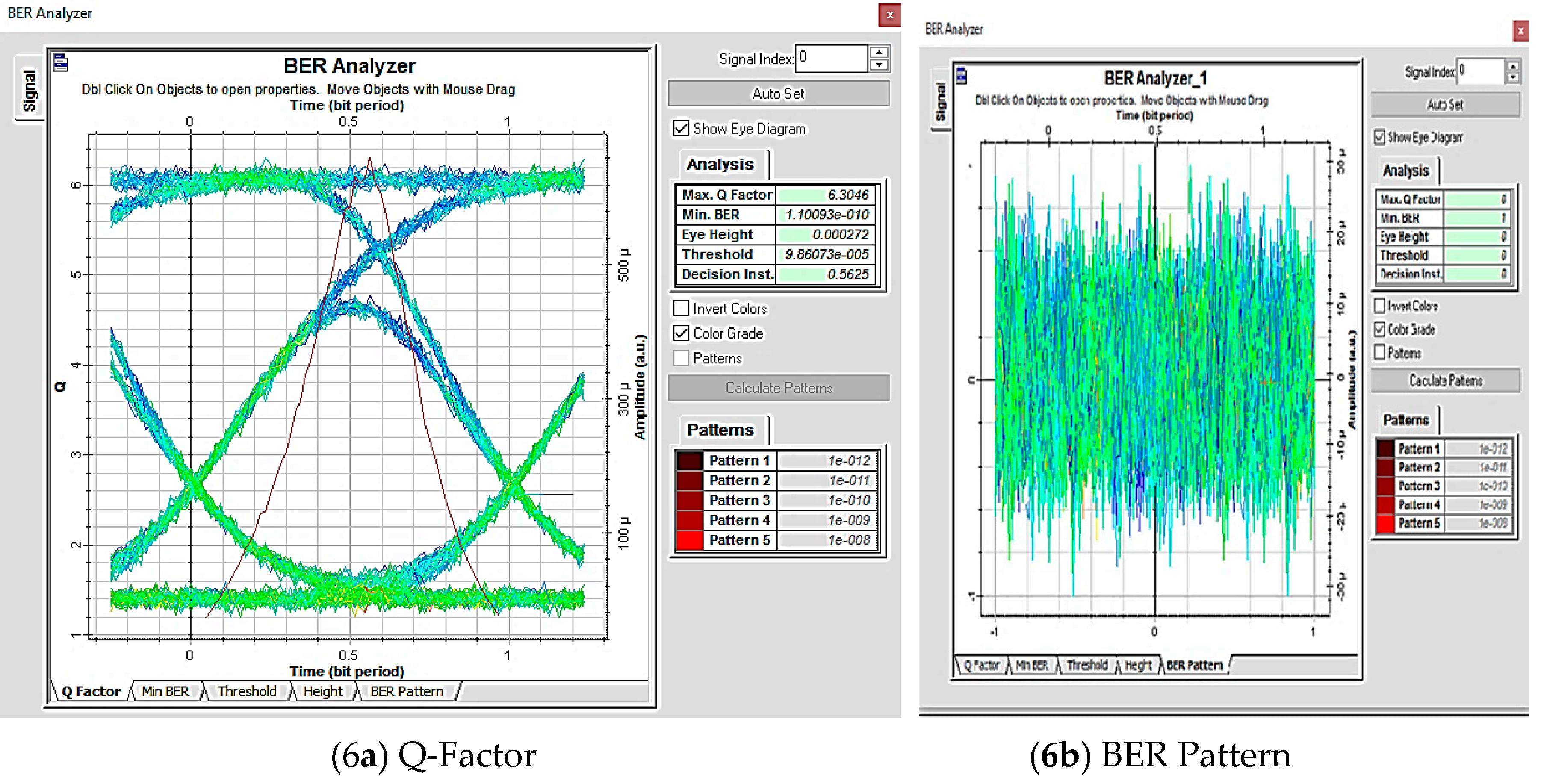
The analysis of the receiver performance can be seen in the simulation run of the BER and the eye diagram diagram. The results can be seen in Figure 6, Figure 7 and Figure 8. For receiver 1 with 5 km fibre length, the BER analyzer shows that the minimum BER for the received signal was 1.1009 × 10⁻¹⁰. The Q-factor for this receiver was 6.3046. The receiver results indicate a perfect performance with referring to the BER value of 10−9, and more than 6 with respect to Q-factor. The noise immunity of the receiver signal affected by the eye diagram height and shown 0.00027 for receiver 1.
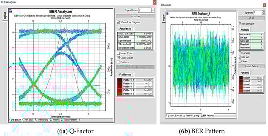
Figure 6.
Bit error rate (BER) analyzer for receiver 1 with 5 km fibre length.
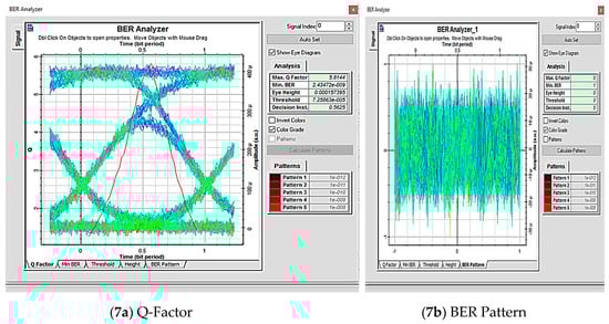
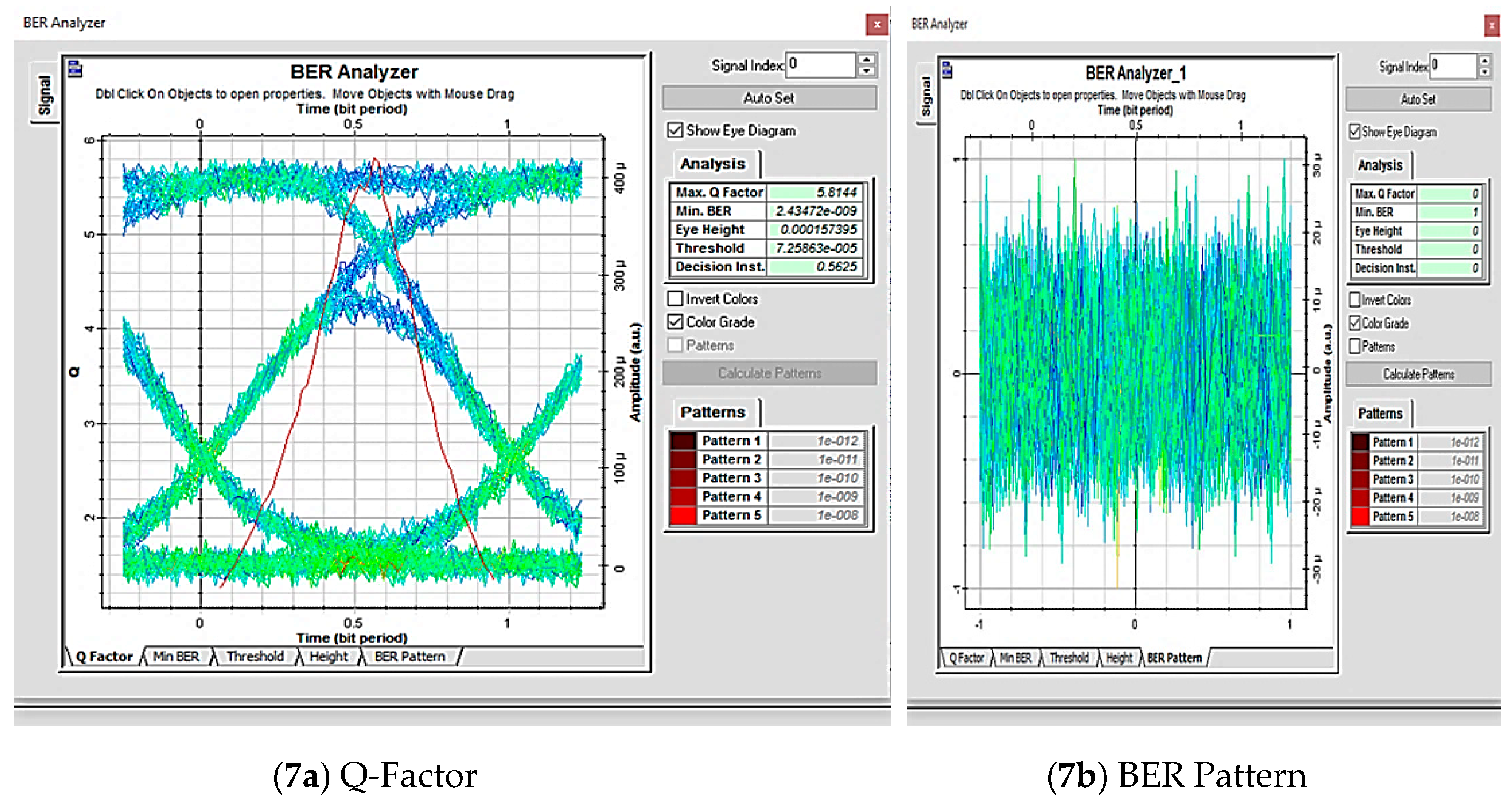
Figure 7.
BER analyzer for receiver 2 with 20 km fiber length.
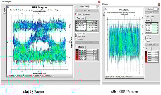
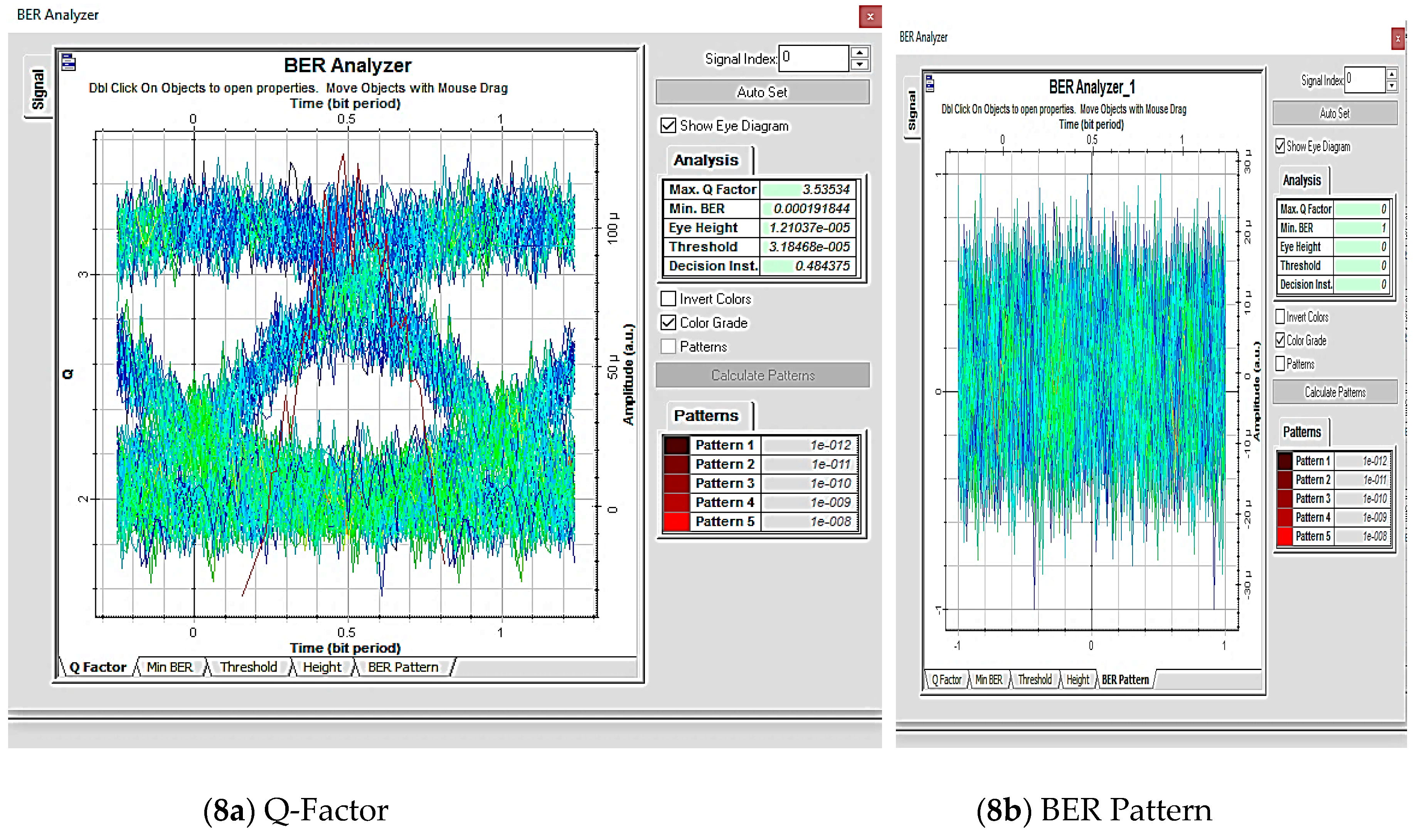
Figure 8.
BER analyzer for receiver 3 with 60 km fiber length.
For receiver 2 with 20 km fibre length, the received signal had a BER of 2.4347 × 10⁻⁹. The Q-factor of the received signal is 5.81. Thus, the BER analyzer shows that this receiver has also received a good signal quality. The eye opening of the eye diagram is 0.000157.
For receiver 3 with 60 km fibre length, the received signal had a BER of 1.918 × 10⁻⁸. The Q-factor of the received signal is 3.53. Here, the BER analyzer shows a bad signal quality. The eye opening of the eye diagram is 0.0000121.
For comparison of the received signal, receiver 1 had a higher immunity to the noise than receiver 3.
As shown in the sample above, BER was 1.10 × 10⁻¹⁰, and the Q-factor is 6.30. This sample result of the eye opening was 2.585 × 10⁻⁵. The sample is a good one because the BER value was less than 10−9, while the Q-factor was a greater than 6. Thus, for receivers with an output just similar to the above sample, then all the proposed parameters can be achieved without difficulty.
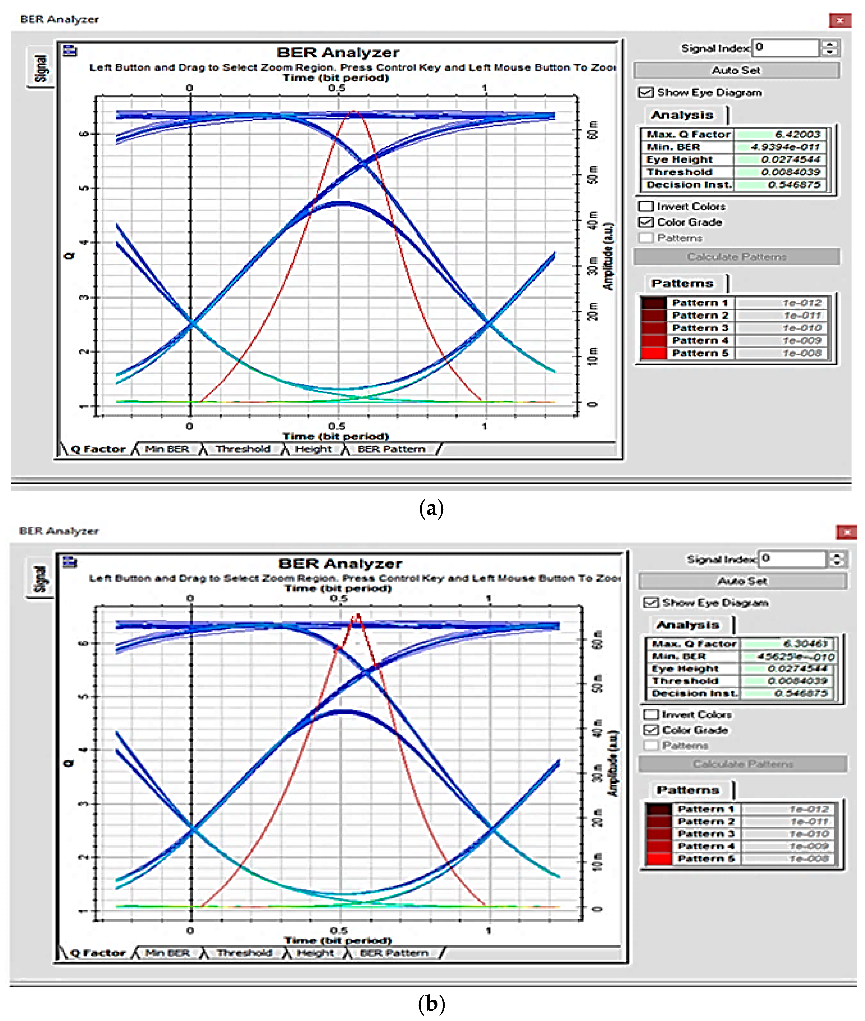
For longer distances, an optical amplifier was added, as shown in Figure 9. A specification of 20 dB gain and noise figure of 5 dB for the amplifier can be applied to the WDM-RoF system. The receiver with 20 km fibre, the BER analyzer gave a better-quality signal without distortion and noise, as shown in Figure 10a. For 60 km fibre length, the received signal had a BER of 4.56 × 10⁻¹⁰. The Q-factor of the received signal was 6.30, as shown in Figure 10b.
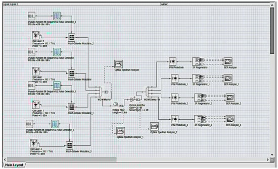
Figure 9.
WDM-RoF system with amplifier.
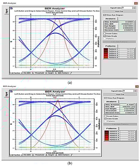
Figure 10.
BER analyzer for receiver with 20 km (a) and 60 km (b) fibre length.
The performances of the receiver for these fibre lengths can be demonstrated in Table 1 without the amplifier and with the amplifier. From the table, it can be seen that the three parameters included in this simulation, BER, Q-factor, and the eye diagram, has been improved and these results show that with the amplifier, the WDM- Rof can be used for long-haul transmission system.

Table 1.
Comparison of the receiver performances for different fibre lengths. Amp: amplifier.
5. Conclusions
The RoF system essentially involves a transmission of analogue signals. It distributes RF signals from CS to BS directly at radio carrier frequency. RoF offers low attenuation with broad bandwidth. It has the advantage of an immunity system to the electromagnetic interference. A roof system employing WDM technique (WDM-RoF) was simulated using OptiSystem simulation software V.13. WDM can be considered the best method used in RoF. WDM allows transmission of multiple signals through a single fibre over large area and can exploit the fibre network bandwidth. In addition, WDM allows the increase of optical fibre capacity compared to simple point to point linking, which only allows a single wavelength to be carried.
For modulating optical sources, an electrical signal was used, with the modulated signal executed through an optical fibre to the receiver side. By directly modulating the signal to the optical fibre, the power consumption could be reduced, while the radio carrier frequency remained high on the BS at antenna side. Moreover, power consumption could be reduced with a simple radio station. The complex devices and equipment were preserved at the CS.
For the WDM-RoF system with different fibre lengths, the result showed that the BER was 1.10 × 10⁻¹⁰, and the Q-factor was 6.30. The sample result of the eye diagram was 2.585 × 10⁻⁵. This system obtained a good result because the BER was less than 10−9, and the Q-factor was more than 6.
The utilisation of EDFA amplifier in this system creates a lot of advantages. It provides low noise figures and has independent polarisation, the most important of which is the large dynamic range. The amplifier has a quite large power transfer efficiency and comparatively flat gain. Accordingly, it can be considered very suitable for use in long distance communication. The compensation of the effects of attenuation and scattering losses with the use of EDFA is greatly explained, which leads to an improvement in the performances of the WDM-RoF system, including the BER and Q-factors, and an increase in the length of the link.
Author Contributions
A.H.A. designed the study, investigations and performed the data analysis. supervised the program of study and provided specialist technical knowledge essential for the completion of this work. A.D.F. provided direction and oversight of the developments needed for the implementation of the Optisystem execution as well as arrangement of the manuscript. All authors discussed the results and contributed to producing the final manuscript.
Funding
This research received no external funding.
Conflicts of Interest
The authors declare no conflict of interest.
References
- Karthikeyan, R.; Prakasam, S. A Survey on Radio over Fiber (RoF) for Wireless Broadband Access Technologies. Int. J. Comput. Appl. 2013, 64. [Google Scholar] [CrossRef]
- Al-Raweshidy, H.; Komaki, S. Radio-over-Fiber Technologies for mobile communication networks, Link design for next generation wireless systems. J. Lightw. Technol. 2010, 28, 136–138. [Google Scholar]
- Sharma, S.R.; Rana, S. Comprehensive Study of Radio over Fiber with different Modulation Techniques—A Review. Int. J. Comput. Appl. 2017, 170, 22–25. [Google Scholar] [CrossRef]
- Kim, H.J.; Song, J.I. All optical frequency down-conversion technique utilizing a four wave mixing effect in a single semiconductor optical amplifier for wavelength division multiplexing radio-over-fiber applications. Opt. Express 2012, 20, 8047–8054. [Google Scholar] [CrossRef] [PubMed]
- Mohan, A. Full Duplex Transmission in RoF System using WDM and OADM Technology. IJERT 2015, 4, 513–516. [Google Scholar]
- Grassi, F.; Mora, J.; Ortega, B.; Capmany, J. Experimental Evaluation of the Transmission in a Low Cost SCM/WDM Radio over Fiber System Employing Optical Broadband Sources and Interferometric Structures. In Proceedings of the 11th International Conference on Transparent Optical Networks, Azores, Portugal, 28 June–2 July 2009; pp. 1–4. [Google Scholar]
- Liu, A.; Wang, X.; Shao, Q.; Song, T.; Yin, H.; Zhao, N. A Low Cost Structure of Radio-over-Fiber System Compatible with WDM-PON. In Proceedings of the 25th Wireless and Optical Communication Conference (WOCC), Chengdu, China, 21–23 May 2016. [Google Scholar]
- Jalil, M.A.; AL-Samarrie, A.K. Radio-over-Fibersystem Capacity Improvements by using Wavelength Division Multiplexing and Subcarrier Multiplexing Techniques. Eng. Technol. J. 2015, 33, 1416–1428. [Google Scholar]
- Basa, A.; Talukder, M.Z.; Islam, M.R. Performance analysis and comparison between coarse WDM and dense WDM. Glob. J. Res. Eng. 2013, 13, 45–52. [Google Scholar]
- Arya Mohan, A.A. Performance comparison of radio over iber system using WDM and OADM with various digital modulation formats. Int. J. Sci. Res. 2015, 4, 2013–2016. [Google Scholar]
- Lundberg, L.; Karlsson, M.; Lorences-Riesgo, A.; Mazur, M.; Torres-Company, V.; Schröder, J.; Andrekson, P.A. Frequency Comb-Based WDM Transmission Systems Enabling Joint Signal Processing. Appl. Sci. 2018, 8, 718. [Google Scholar] [CrossRef]
- Singh, S.P.; Sengar, S.; Bajpai, R.; Iyer, S. Next-generation variable-line-rate optical WDM networks: Issues and Challenges. J. Opt. Commun. 2013, 34, 331–350. [Google Scholar] [CrossRef]
- Mohammed, H.A.; Ali, A.H. Effect of some security mechanisms on the Qos VoIP application using OPNET. Int. J. Curr. Eng. Technol. 2013, 3, 1626–1630. [Google Scholar]
- Al-Raweshidy, H.; Komaki, S. Radio over Fiber Technology for the Mobile Communications Networks; Artech House, Inc.: Norwood, MA, USA, 2002. [Google Scholar]
- Olmos, J.J.; Monroy, I. Reconfigurable Radio-Over-Fiber Networks. J. Opt. Commun. Netw. 2015, 7, 23–28. [Google Scholar] [CrossRef]
- Abdulrazzaq, A.A.; Abid, A.J.; Ali, A.H. QoS Performances Evaluation for Mobile WIMAX Networks based on OPNET. Int. J. Appl. Eng. Res. 2018, 13, 6545–6550. [Google Scholar]
- Marwanto, A.; Idrus, S.M.; Sahmah Mohd, A. Performance Analysis of EDFA for FOR SCM/WDM Radio over Fiber Communication Link. Available online: http://citeseerx.ist.psu.edu/viewdoc/download?doi=10.1.1.522.5803&rep=rep1&type=pdf (accessed on 20 December 2018).
- Husein, A.H.M.; El Nahal, F.I. Optimal design of 32 channels spectrum slicing WDM for optical fiber access network system. Optik 2014, 125. [Google Scholar] [CrossRef]
- El-Nahal, F.I. A WDM-PON with DPSK modulated downstream and OOK modulated upstream signals based on symmetric 10 Gbit/s wavelength reused bidirectional reflective SOA. Optoelectron. Lett. 2017, 13, 67–69. [Google Scholar] [CrossRef]

© 2019 by the authors. Licensee MDPI, Basel, Switzerland. This article is an open access article distributed under the terms and conditions of the Creative Commons Attribution (CC BY) license (http://creativecommons.org/licenses/by/4.0/).