Article

Critical Velocity of High-Performance Yarn Transversely Impacted by Razor Blade

1
School of Aeronautics and Astronautics, Purdue University, West Lafayette, IN 47907, USA
2
School of Materials Engineering, Purdue University, West Lafayette, IN 47907, USA
*
Author to whom correspondence should be addressed.
Fibers 2018, 6(4), 95; https://doi.org/10.3390/fib6040095
Submission received: 12 November 2018 / Revised: 2 December 2018 / Accepted: 5 December 2018 / Published: 7 December 2018

Abstract

:
A ballistic parameter that influences the ballistic performances of a high-performance yarn is the critical velocity. The critical velocity is defined as the projectile striking velocity that causes instantaneous rupture of the yarn upon impact. In this study, we performed ballistic experiments to determine the critical velocity of a Twaron® yarn transversely impacted by a razor blade. A high-speed camera was integrated into the experimental apparatus to capture the in-situ deformation of the yarn. The experimental critical velocity demonstrated a reduction compared to the critical velocity predicted by the classical theory. The high-speed images revealed the yarn specimen failed from the projectile side toward the free end when impacted by the razor blade. To improve the prediction capability, the Euler–Bernoulli beam and Hertzian contact models were used to predict the critical velocity. For the Euler–Bernoulli beam model, the critical velocity was obtained by assuming the specimen ruptured instantaneously when the maximum flexural strain reached the ultimate tensile strain of the yarn upon impact. On the other hand, for the Hertzian contact model, the yarn was assumed to fail when the indentation depth was equivalent to the diameter of the yarn. The errors between the average critical velocities determined from experiments and the predicted critical velocities were around 19% and 48% for the Euler–Bernoulli beam model and Hertzian contact model, respectively.

1. Introduction

The critical velocity is defined as the projectile striking velocity that causes instantaneous rupture of the specimen under transverse impact. When impacted at or above the critical velocity, the transverse displacement of the specimen is insignificant prior to failure [1,2]. The classical theory developed by Smith et al. [1] enabled some of the mechanical properties, such as transverse wave speed and critical velocity, to be predicted using only the axial mechanical properties. In general, the predicted transverse wave velocity using the classical theory is in good agreement with that obtained from the experiments [3,4]. However, the Smith theory always overestimates the critical velocity [5,6,7].
Several studies were performed in an effort to understand why such discrepancies exist between the critical velocity determined from the Smith theory and experiments. For example, Bazhenov et al. [7] shot a 3-cm spherical metal ball with a striking velocity of 670 m/s into an aramid yarn. These specimens fractured at a striking velocity lower than the theoretical critical velocity. The authors suggested that the non-linear constitutive material properties of the yarns at a large deformation caused the theoretical critical velocity to be overestimated [7]. In addition, the authors also pointed out that non-linear interaction between the projectile and specimen caused the yarn to rupture at a lower critical velocity [7].
Chocron et al. [3,6] studied the wave propagation developed in yarns impacted by flat head projectiles such as the fragmented simulating projectile (FSP) and the right circular cylinder. The authors suggested the reason that the Smith theory overestimated the critical velocity was that the specimen “bounced-off” the face of a flat head projectile [3,6]. When a yarn was impacted by a flat head projectile, two waves were generated at both edges of the projectile and propagated toward the center of the projectile [3]. The superimposed waves caused the transverse particle velocity to double. This phenomenon caused the yarn to bounce off the face of the projectile and ultimately led to the decrease in critical velocity [3]. Such phenomenon was also observed experimentally by Field and Sun [4].
Recently, Hudspeth et al. [2,5,8] suggested that the reduction in the critical velocity was caused by the multi-axial stress developed in the yarns during transverse impact. Kevlar® KM2, Dyneema® SK76, and AuTx® yarns were loaded in the transverse direction under quasi-static conditions using a universal material testing machine (MTS 810) with three different projectiles: razor blade, 0.30-cal FSP, and 0.30-cal round [2,5]. The axial rupture strain determined from quasi-static transverse loading experiments for all three projectiles showed a demonstrative reduction compared to the ultimate tensile strain, with the razor blade being the lowest, followed by 0.30-cal FSP and 0.30 round projectiles [2,5]. For the FSP projectile, most of the fibers failed at the corners, suggesting that multi-axial stress was developed and caused the stress concentration to occur at the corners [5]. Based on these studies, the authors suggested that a possible way to improve the Smith model was to substitute the ultimate tensile strain in the Smith theory with the rupture strain determined from quasi-static transverse loading experiments [5]. In addition, a 20-mm powder gun was utilized to determine the critical velocities of yarns impacted by these three projectiles [2]. The results showed that the yarns impacted by a razor blade had the lowest critical velocity, followed by 0.30-cal FSP and 0.30-cal round [2].
Clearly, the projectile nose shape is an important parameter that influences the critical velocity. The projectile–yarn interaction during transverse impact creates multiaxial loads on the yarn and generates additional waves such as the flexural wave [9,10,11]. These phenomena were not considered in the Smith theory, causing the predicted critical velocity to be overestimated. In this study, we performed ballistic experiments to determine the critical velocity for a Twaron® yarn impacted by a razor blade. In addition, we improved the prediction capability by using two different models, the Euler–Bernoulli beam model and the Hertzian contact model, to predict and compare the critical velocity with the experimental results.

2. Materials and Methods

The yarn specimens used in this study were strands of Twaron® 2040 yarns extracted from plain weave single ply CT 709 Twaron® in the warp direction. The quasi-static mechanical properties of this yarn were determined in previous studies and are tabulated in Table 1 [12,13].

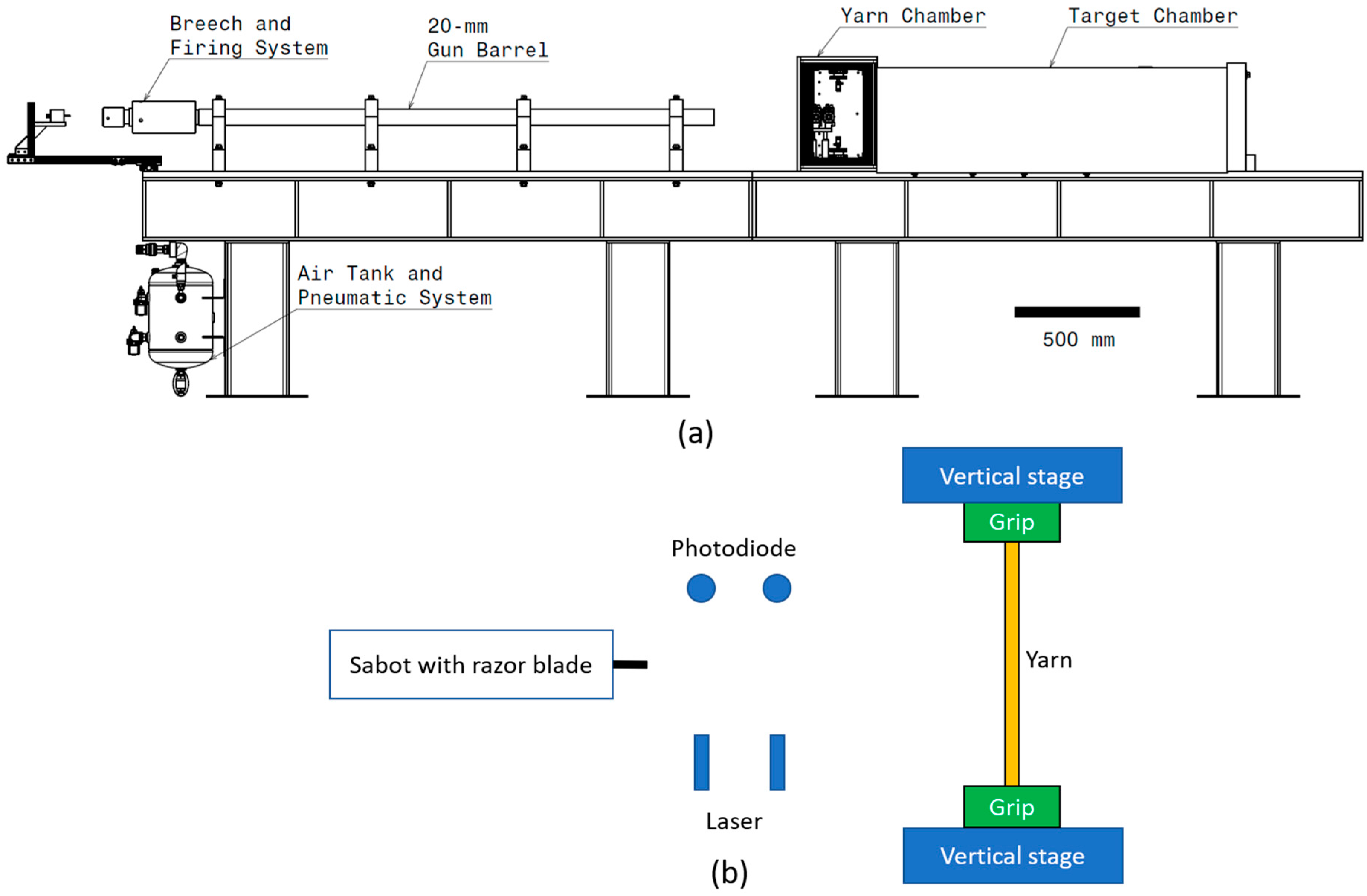
2.1. Ballistic Experiments

A gas/powder gun was designed and developed to perform the ballistic experiments as shown in Figure 1a.
The apparatus consisted of a gun barrel, a target chamber, and a yarn chamber. The gun barrel possessed an inner diameter of 20 mm and a length of 2.1 m. Figure 1b presents the schematic inside the yarn chamber, which included a pair of lasers and photodiodes to measure the projectile striking velocity. The method of attaching the yarn specimens to the grips was presented in [12] with the exception that the grips were mounted vertically instead of at 45 degrees. The Twaron® 2040 warp yarns possessed a gage length of 190 mm. Two vertical stages were used to assist in positioning the yarns as shown in Figure 1b. The projectiles used in these experiments were commercially available razor blades. The razor blades were cut to a length of 16.5 mm using a precision wafering saw. Sabots were used to ensure the razor blade fitted in the gun barrel, as shown in Figure 2a.
The sabots were made by casting polyurethane foam in a mold. A slot was cut at the top of each sabot using a precision wafering saw. The purpose of this slot was to allow the razor blade to be placed on top of the sabot which was then secured on the sabot with cyanoacrylate adhesive. Another parallel cut was made at the rear end of the sabot to help align the sabot inside the gun barrel. Such an alignment ensured the contact angle between the blade and the yarn remained perpendicular. The razor blade was made of steel and the average mass of a sabot together with a razor blade (Ms) was 28.4 g. The radius of curvature of the razor blade was obtained via scanning electron microscopy (SEM) at three different locations. Figure 2b shows a representative SEM image of the radius of curvature of a razor blade. The average radius of curvature of the razor blade ( R s ) was 2 µm. Compressed gas was used as a propellent when the projectile striking velocity was below 120 m/s. To achieve a higher striking velocity, smokeless gun powders were used. Finally, a high-speed camera was integrated into the experimental apparatus to capture the in-situ dynamic impact event of the yarn subjected to a razor blade.

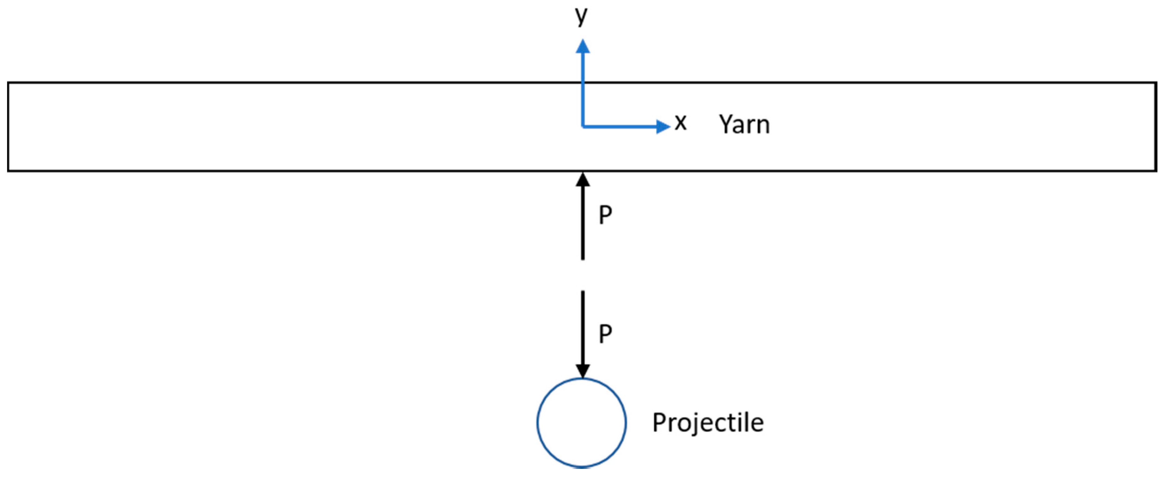
2.2. Euler–Bernoulli Beam Model

A possible reason for the Smith theory to overestimate the critical velocity is that the theory assumes bending is negligible [9,10,12]. Later in the results section, we showed that when the yarn was impacted by a razor blade above the critical velocity, the yarn deflection was small prior to rupture. In addition, the length of the specimen was much larger than the diameter. These criteria satisfied two of the assumptions in the Euler–Bernoulli beam theory [15]. Thus, we modeled the specimen as a Euler–Bernoulli beam with infinite length subjected to transverse impact by a pointed projectile. A Cartesian coordinate was setup with x = 0 at the impact location. Using Euler–Bernoulli beam theory with the assumption that damping in the specimen is negligible the equation of motion of a free vibration beam is given in Equation (1) [15]
E I y 4 v y x 4 + ρ y A y 2 v y t 2 = 0
where vy, Iy, ρy and Ay are transverse displacement, second moment of inertia, density, and cross-sectional area, respectively. Utilizing spectral analysis [15], the solution for Equation (1) has the form of
v y ( x , t ) = ( A e i β x + B e β x + C e i β x + D e β x ) e i ω t β = ρ y A y E I y 4 ω
where ω is the angular frequency. A, B, C, and D are the integration constants. Equation (2) describes the two transverse waves propagating in the specimen when subjected to a point disturbance, a right running wave ( v y i ) and a left running wave ( v y r ), as shown in Equation (3) [15].
v y i ( x , t ) = ( A e i β x + B e β x ) e i ω t
v y r ( x , t ) = ( C e i β x + D e β x ) e i ω t
The first terms in Equations (3a) and (3b) are wave solutions and the second terms are predominantly spatial damped vibrations [15]. The integration constant could be evaluated by imposing a symmetric boundary condition at the impact location as given in Equation (4).
v y i ( 0 , t ) = v y r ( 0 , t ) v y i x ( 0 , t ) = v y r x ( 0 , t ) = 0
The transverse particle velocity ( v ˙ y i ) and bending strain ( ε x x ) developed in the specimen is defined as:
v ˙ y i ( x , t ) = v y i t ε x x ( x , y , t ) = y 2 v y i x 2 .
From Equations (3)–(5) at the impact location (x = 0), the particle velocity and bending strain are related by Equation (6).
v ˙ y i ( 0 , t ) = 1 y E I y ρ y A y ε x x ( 0 , y , t )
When the specimen is impacted by the razor blade at the impact location, the yarn moves with a transverse particle velocity equivalent to projectile striking velocity (i.e., v ˙ y i ( 0 , t ) = V s ). It was assumed that the specimen would rupture if the bending strain reached the ultimate tensile strain. Hence, if the ultimate tensile strain of the yarn was known, the projectile critical striking velocity ( V c r i t ) that would cause instantaneous rupture of the yarn could be determined from Equation (7).
V c r i t = 1 y E I y ρ y A y ε U T S
Furthermore, it was assumed that the yarn possessed a circular cross-section and the interactions between fiber–fiber were negligible. For a specimen with a circular cross-section, the maximum bending strain occurs at y = r. From Equation (7), with y = r, the critical velocity is given in Equation (8),
V c r i t = 1 2 C 0 ε U T S
where C 0 = E / ρ y is the axial wave speed. The predicted critical velocity obtained from the Euler–Bernoulli model was then compared with the experimental results.

2.3. Hertzian Contact Model

A common issue in the Smith model [1] and the Euler–Bernoulli beam model is that the critical velocity only depends on the mechanical properties of the yarn. However, experimental results revealed that the critical velocity was highly dependent on the projectile nose shape [2,12]. As the projectile radius of curvature decreased, the critical velocity also decreased [2]. Therefore, in this model, we considered the projectile–yarn interaction and modeled the projectile and the yarn as a rigid sphere and Euler–Bernoulli beam, respectively. Figure 3 presents a free body diagram of a yarn impacted by a spherical projectile. Upon impact, a contact force (P) was generated and acted on both the projectile and the yarn.
For a rigid body sphere possessing a mass (Ms) subjected to a contact force (P), the equation of motion is given in Equation (9),
M s v ¨ s = P
where vs is the displacement of the spherical projectile (in the y-direction) upon impact. For a dynamic Euler–Bernoulli beam possessing an infinite length, the relationship between the transverse velocity and load P at the point of impact (x = 0) is given in Equation (10) [15,16].
v ˙ y = 1 2 2 π ( E y I y ) 1 4 ( ρ y A y ) 3 4 0 t P ( τ ) t τ d τ
We neglected the fiber‒fiber interaction by assuming the yarn possessed a cross section with the shape of a circle and a cross-sectional area equal to the sum of the cross-section of all the fibers in the yarn. Upon impact, the contact force can be related to the displacement of the projectile and the transverse deflection of the beam using the Hertzian contact law as given in Equation (11) [16,17].
P = K ( v s v y ) 3 2 K = 4 3 E R E = ( 1 E s + 1 E t y ) 1 R = ( 1 R s + 1 R y ) 1 R s
where Es, and E t y are the Young’s modulus of the sphere (projectile) and transverse modulus of the beam (yarn), respectively. Twaron® is a p-phenylene terephthalamide (PPTA) fiber where the mechanical properties in the axial direction are relatively rate-insensitive [18]. However, the transverse mechanical properties are rate sensitive [14]. The dynamic transverse modulus of Twaron® 2040 yarn or fiber has not yet been determined. Therefore, in this study, we assumed that the transverse modulus of the yarn is equivalent to the dynamic transverse modulus of the fiber. Experimental work performed by Guo et al. [14] indicated that at high-rate, the dynamic transverse modulus for PPTA fiber increased by 2.95 times compared to that of the quasi-static. Therefore, in this study, it was assumed that the transverse modulus for Twaron® 2040 yarn also increased by a similar order of magnitude [13,14]. The projectile was made from steel with a Young’s modulus of 200 GPa. Ry is the radius of curvature of the yarn. Upon impact, the yarn remained flat, resulting in an infinite radius of curvature ( R y = ). Equations (9) and (10) are the equations of motion for a beam impacted by a spherical projectile. Note that Equation (10) is valid only at x = 0. The initial conditions for these equations of motion are
v s ( 0 ) = 0 v ˙ s ( 0 ) = V s v y ( 0 ) = 0
where Vs is the projectile’s striking velocity. Equations (9)–(12) were solved numerically using the finite difference method with the time step of 1 ns and 10,000 steps. The equations of motion were converted into a system of first order differential equations. First order forward differencing was implemented on the initial condition to obtain the solution for the initial time step [19]. For other time steps, a central differencing scheme, which is second order accurate in time, was used to formulate explicit equations to solve these differential equations.

3. Results

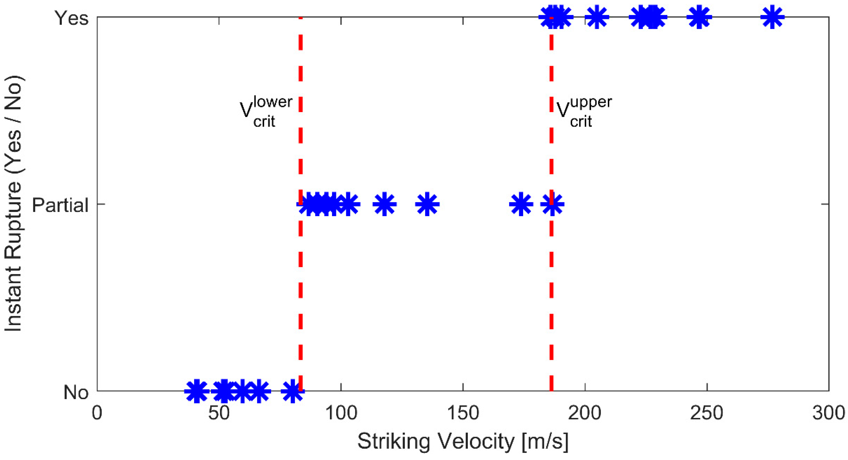
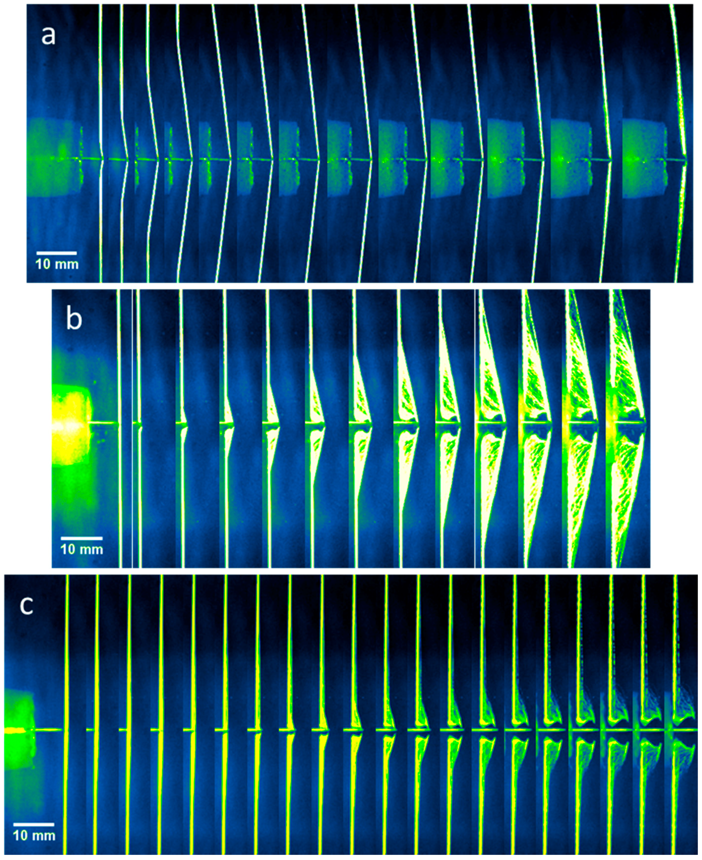
3.1. Ballistic Experiments

Ballistic experiments were performed to determine the critical velocity when the Twaron® yarn was transversely impacted by a razor blade. When a projectile impacts a yarn transversely, the critical velocity has a range [2]. Below the low end of the critical velocity, the yarn is not ruptured. Above the higher end of the critical velocity, the yarn ruptures immediately. The yarn is partially ruptured when impacted within the critical velocity range. Figure 4 shows the high-speed images when the yarn was impacted at (a) below, (b) within the range of, and (c) above the critical velocity.
When the yarn was transversely impacted by a razor blade, the initial deformation of the yarn fell into one of the three possible cases; instantaneous rupture, partial rupture or no rupture, as shown in Figure 4. When impacted below the critical velocity, a transverse wave was observed to propagate in the yarn, causing the yarn to deform into a triangular shape very similar to the deformation described by Smith et al. [1]. As the striking velocity increased, some of the fibers ruptured upon contact. The fibers that did not rupture deformed into a triangular shape similar to the deformation at low velocity. When the projectile impacted at a velocity higher than the critical velocity, the yarn ruptured instantaneously. The transverse displacement of the yarn prior to the failure was insignificant as compared to the previous two cases. Although visually distinguishable, it is important to note that such a method to determine the case each experiment falls into is qualitative in nature [2]. Interestingly, from Figure 4, the fibers of the yarn were observed to fail progressively from the razor blade side to the other free end. Figure 5 plots the yarn condition upon impact versus the striking velocity.
From Figure 5, some fibers were partially ruptured upon impact at a striking velocity between 83 m/s and 186 m/s. These boundaries indicated the lower and upper limits of the critical velocity for the Twaron® yarns transversely impacted by a razor blade. Such a method to determine the critical velocity was very similar to those reported by Hudspeth et al. [2].

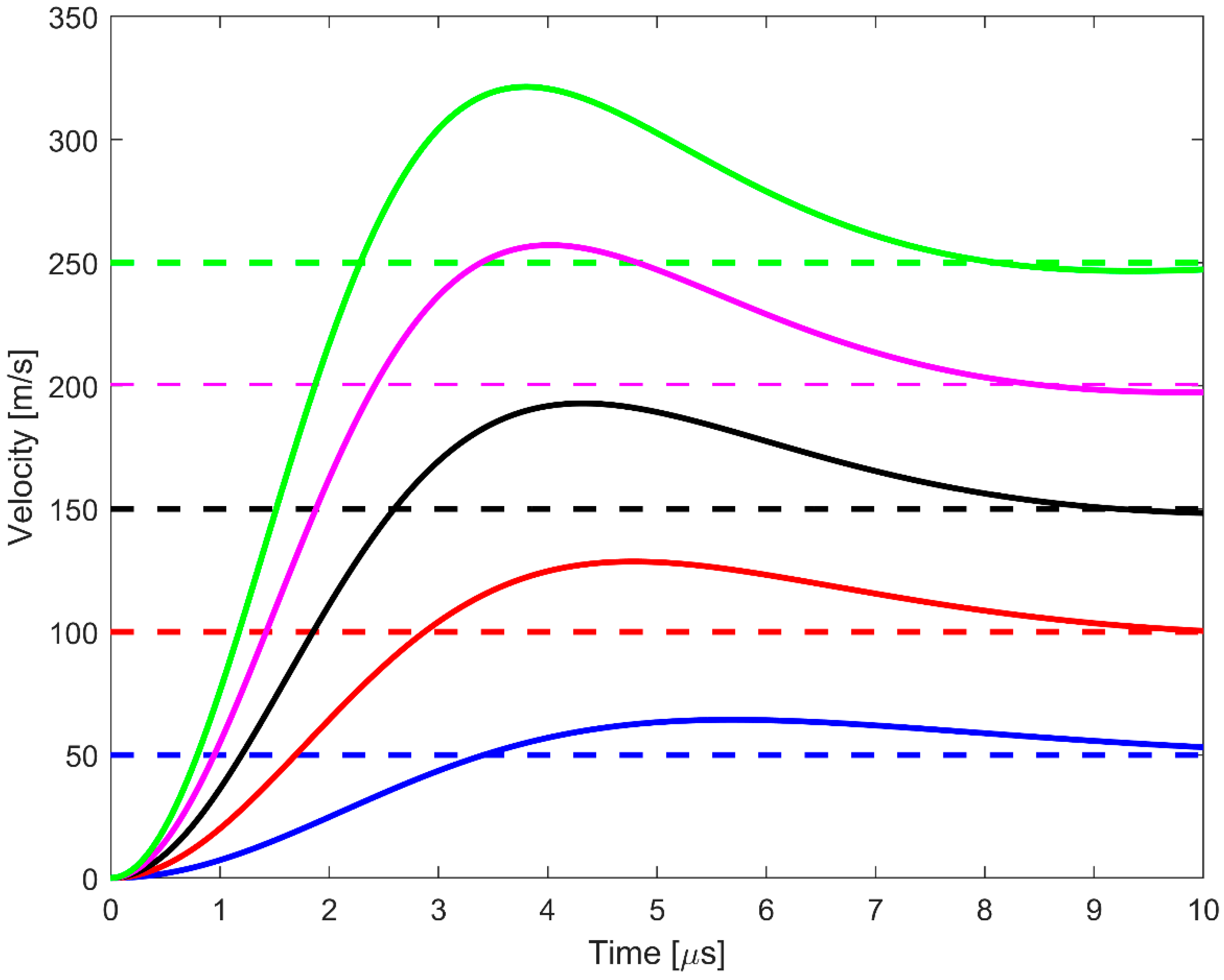
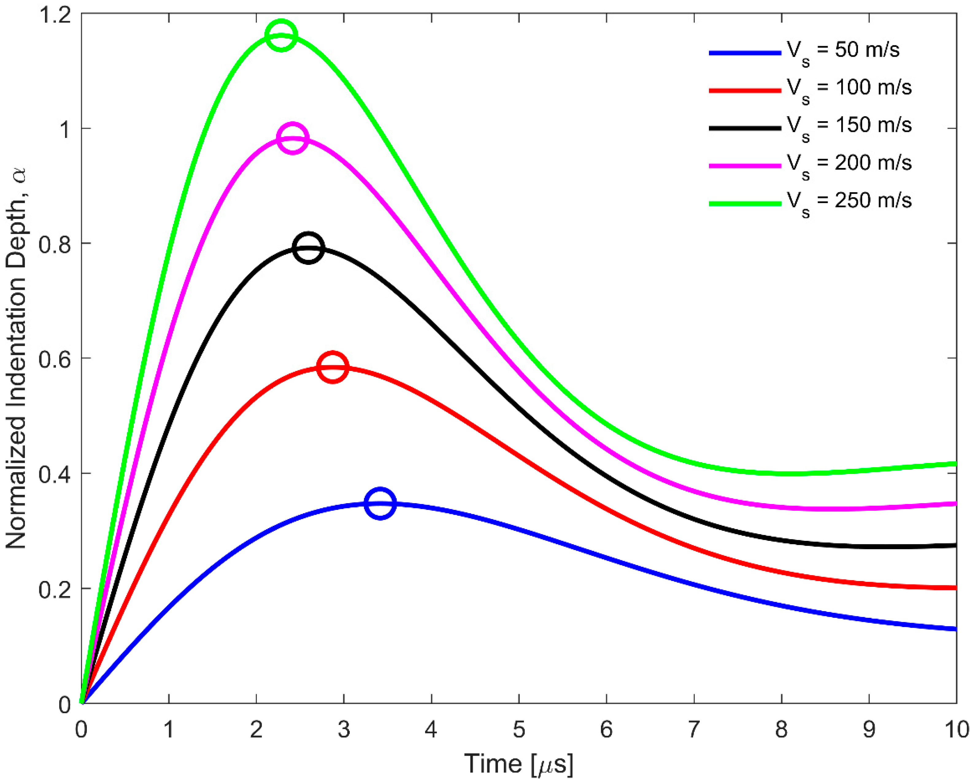
3.2. Hertzian Contact Model
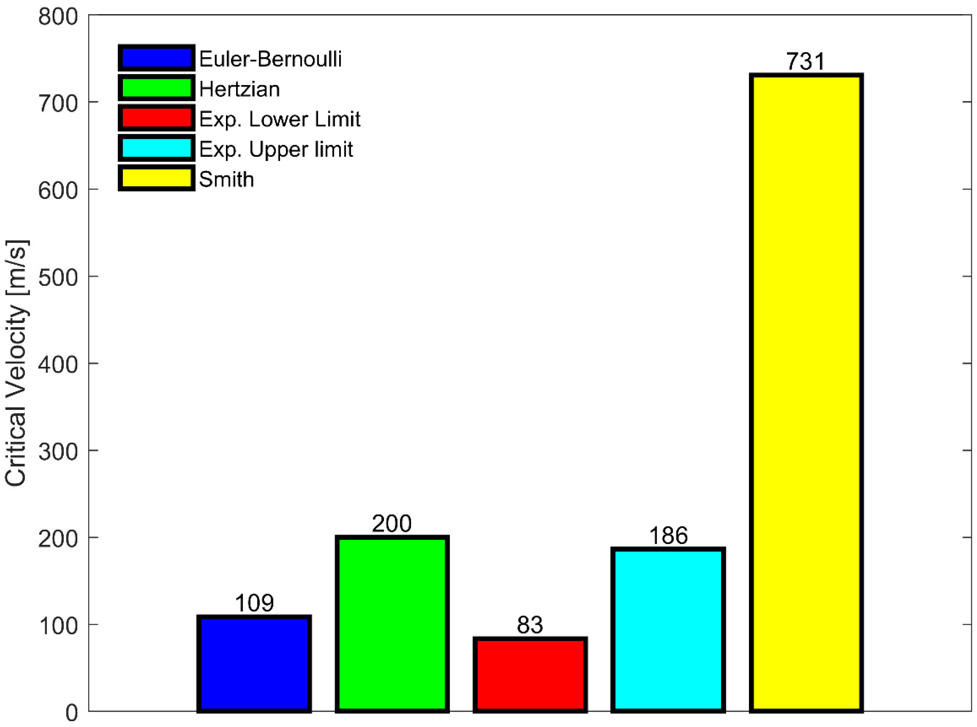
Figure 6 shows the velocity histories for both projectile and yarn at the point of impact at several striking velocities ranging from 50 m/s to 250 m/s. These results were obtained by solving Equations (9)–(12) using the parameters listed in Table 1. Since the mass of the projectile was significantly heavier compared to the yarn, the projectile velocity remained nearly constant throughout the event. Initially, the yarn was at rest. Once the yarn was impacted, the velocity at the point of impact increased and even surpassed the projectile’s striking velocity. Eventually, the yarn velocity decreased and reached the projectile’s striking velocity, causing the projectile and the yarn to move at the same speed.
The normalized indentation depth ( α ) is defined as the difference between the projectile and yarn displacements normalized by the yarn diameter ( 2 r y ) as given in Equation (13).
α = v s v y 2 r y
Figure 7 shows the normalized indentation depth at several striking velocities. Initially, the projectile and yarn displacements were zero, resulting in zero indentation depth. Since the yarn required a finite amount of time to reach the projectile striking velocity, the indentation depth increased initially. As the velocity of the yarn exceeded the projectile striking velocity, the indentation depth decreased. Since the projectile displacement was higher than the yarn displacement, the indentation depth did not reduce to zero. Finally, as the yarn velocity approached the projectile striking velocity, the normalized indentation depth reached a plateau when the two velocities converged, as shown in Figure 7.
As the projectile’s striking velocity increased, it was observed that the normalized indentation depth also increased. At a striking velocity below 200 m/s, the normalized indentation depth was less than unity. Physically, this means that the projectile was behind the yarn for all time, and the transverse displacement of the yarn at the point of impact would increase to a point that violates the assumption of small deformation in the Euler-Bernoulli beam theory, meaning the yarn would deform according to the Smith theory.
However, at a striking velocity above 200 m/s, it was observed that the normalized indentation depth was more than unity. A normalized indentation depth of more than unity means the projectile was ahead of the yarn. Physically, this means that the projectile sheared through the yarn and caused the yarn to fail, which was very similar to that observed in Figure 3c. When the projectile strikes at 200 m/s, the Hertzian contact model revealed that the maximum indentation depth was around 0.98, which was very close to unity. Therefore, the striking velocity of 200 m/s was the critical velocity for Twaron® 2040 yarn impacted by a razor blade predicted by the Hertzian contact model.

4. Discussion

The critical velocity obtained from the experiments, Euler‒Bernoulli beam model, Hertzian contact model, and Smith model were compared, as shown in Figure 8.
For the Smith theory, the predicted critical velocity ( V S m i t h ) could be obtained by using Equation (14) [1,5].
V S m i t h = C 0 ε U T S ( 1 + ε U T S ) ( ε U T S ( 1 + ε U T S ) ε U T S ) 2
Using the mechanical properties listed in Table 1, the critical velocity predicted from the Smith theory was around 731 m/s. The predicted critical velocity overestimated the experimental results by at least 290%. Such a discrepancy in critical velocity agreed with the experimental results reported in the literature [2,7].
On the other hand, for the Euler–Bernoulli beam model, the predicted critical velocity using Equation (8) is 109 m/s. From Figure 8, it was observed that the predicted critical velocity agreed well with the experimental results, especially when predicting the lower limit of the critical velocity. The Euler–Bernoulli model assumed that the yarn failed instantaneously when the maximum bending strain reached the ultimate tensile strain. Physically, this means that only one fiber located near the free end would fail; as a result, the predicted critical velocity was closer to the lower end. From the high-speed images presented in Figure 4, the fiber failed progressively from the razor blade toward the other free end. However, for the Euler–Bernoulli beam theory, the maximum bending strain occurred at the free end. The failure should also initiate from the free end, which contradicted to what was observed experimentally. To address such an issue, we used the Hertzian contact theory to model the projectile–yarn interaction and predict the critical velocity.
Unlike the Smith model and the Euler–Bernoulli beam model, the Hertzian contact model accounts for the projectile–yarn interaction. In addition, the failure criterion implemented in the Hertzian contact theory required all the fibers in a yarn to fail. As a result, the predicted critical velocity agreed well with the upper limit of the critical velocity, as shown in Figure 8.
To have a better comparison between the models, the errors between the predicted critical velocities from the Smith, Hertzian contact and Euler–Bernoulli models and the average critical velocity determined from experiments were determined. These errors were 440%, 48%, and 19% for the Smith, Hertzian contact and Euler–Bernoulli models, respectively. Even though the Euler–Bernoulli beam model had the lowest error, the failure mechanism predicted by this model did not agree with the observations from the high-speed images. On the other hand, the Hertzian contact model accounted for the projectile–yarn interaction. The failure criterion using indentation depth was formulated based on experimental observations. As a result, the predicted velocity was in good agreement with the experimental results.

5. Conclusions

Ballistic experiments were performed to determine the critical velocity that caused the yarn to fail instantaneously when impacted by a razor blade. The Euler–Bernoulli beam model and Hertzian contact model were used to predict the critical velocity. The Euler–Bernoulli beam assumed that the yarn failed instantaneously when the maximum bending strain reached the ultimate tensile strain. The predicted critical velocity from the beam model was closer to the lower limit of the critical velocity with an error of 31% between these two velocities. On the other hand, the Hertzian contact considered the projectile yarn interaction. The yarn was assumed to fail when the indentation depth was equal to the yarn’s diameter. The predicted critical velocity was in good agreement with the upper limit of the experimental critical velocity, with an error of 7.5% between these two velocities.

Author Contributions

B.H.L., J.-M.C., and W.C analyzed the results and contributed in discussion. B.H.L., J.-M.C., B.C., and Y.N. performed the experiments. W.C. supervised the project direction.

Funding

This research was funded by US Army PEO Soldier with grant number W91CRB-14-C-0025. In addition, this research was partially sponsored by the Army Research Laboratory and was accomplished under Cooperative Agreement Number W911NF-12-2-0022.

Acknowledgments

The authors would like to express their gratitude to US Army PEO Soldier and Army Research Laboratory for providing the financial support for this work. In addition, the authors thank Jinling Gao for performing SEM to obtain the radius of curvature of the razor blade.

Conflicts of Interest

The authors declare no conflicts of interest. The funding sponsors had no role in the design of the study; in the collection, analyses, or interpretation of data; in the writing of the manuscript; and in the decision to publish the results

References

  1. Smith, J.C.; McCrackin, F.L.; Schiefer, H.F. Stress-Strain Relationships in Yarns Subjected to Rapid Impact Loading: Part V: Wave Propagation in Long Textile Yarns Impacted Transversely. Text. Res. J. 1958, 28, 288–302. [Google Scholar] [CrossRef]
  2. Hudspeth, M.; Chu, J.-M.; Jewell, E.; Lim, B.; Ytuarte, E.; Tsutsui, W.; Horner, S.; Zheng, J.; Chen, W. Effect of projectile nose geometry on the critical velocity and failure of yarn subjected to transverse impact. Text. Res. J. 2016, 87, 953–972. [Google Scholar] [CrossRef]
  3. Chocron, S.; Kirchdoerfer, T.; King, N.; Freitas, C.J. Modeling of fabric impact with high speed imaging and nickel-chromium wires validation. J. Appl. Mech. 2011, 78, 051007. [Google Scholar] [CrossRef]
  4. Field, J.; Sun, Q. A high speed photographic study of impact on fibres and woven fabrics (from 19th International Congress on High-Speed Photography and Photonics 1990). SPIE Milest. Ser. MS 1995, 109, 57–66. [Google Scholar]
  5. Hudspeth, M.; Chen, W.; Zheng, J. Why the Smith theory over-predicts instant rupture velocities during fiber transverse impact. Text. Res. J. 2015, 86, 743–754. [Google Scholar] [CrossRef]
  6. Walker, J.D.; Chocron, S. Why Impacted Yarns Break at Lower Speed Than Classical Theory Predicts. J. Appl. Mech. 2011, 78, 051021. [Google Scholar] [CrossRef]
  7. Bazhenov, S.; Dukhovskii, I.; Kovalev, P.; Rozhkov, A. The fracture of SVM aramide fibers upon a high-velocity transverse impact. Polym. Sci. Ser. AC/C Vysokomolekuliarnye Soedineniia 2001, 43, 61–71. [Google Scholar]
  8. Hudspeth, M.; Li, D.; Spatola, J.; Chen, W.; Zheng, J. The effects of off-axis transverse deflection loading on the failure strain of various high-performance fibers. Text. Res. J. 2016, 86, 897–910. [Google Scholar] [CrossRef]
  9. Sockalingam, S.; Gillespie, J.W., Jr.; Keefe, M. Dynamic modeling of Kevlar KM2 single fiber subjected to transverse impact. Int. J. Solids Struct. 2015, 67–68, 297–310. [Google Scholar] [CrossRef]
  10. Sockalingam, S.; John, W.; Gillespie, J.; Keefe, M. Modeling the fiber length-scale response of Kevlar KM2 yarn during transverse impact. Text. Res. J. 2017, 87, 2242–2254. [Google Scholar] [CrossRef]
  11. Hudspeth, M.C. Multi-Axial Failure of High-Performance Fiber during Transverse Impact. Ph.D. Thesis, Purdue University, West Lafayette, IN, USA, 2016. [Google Scholar]
  12. Lim, B.H.; Chu, J.-M.; Chen, W. Mechanical Behavior of High-Performance Yarns Transversely Loaded by Different Indenters. Fibers 2018, 6, 69. [Google Scholar] [CrossRef]
  13. Guo, Z.; Chen, W.; Zheng, J. Improved quasi-static twin-fiber transverse compression of several high-performance fibers. Text. Res. J. 2018. [Google Scholar] [CrossRef]
  14. Guo, Z.; Casem, D.; Hudspeth, M.; Nie, X.; Sun, J.; Chen, W. Transverse compression of two high-performance ballistic fibers. Text. Res. J. 2016, 86, 502–511. [Google Scholar] [CrossRef]
  15. Doyle, J.F. Wave Propagation in Structure: Spectral Analysis Using Fast Discrete Fourier Transforms; Springer: New York, NY, USA, 1997. [Google Scholar]
  16. Doyle, J.F. Guided Explorations of the Mechanics of Solids and Structures; Cambridge University Press: Cambridge, UK, 2009. [Google Scholar]
  17. Popov, V.L. Contact Mechanics and Friction; Springer: Berlin/Heidelberg, Germany, 2010. [Google Scholar]
  18. Cheng, M.; Chen, W.; Weerasooriya, T. Mechanical Properties of Kevlar® KM2 Single Fiber. J. Eng. Mater. Technol. 2005, 127, 197–203. [Google Scholar] [CrossRef]
  19. Versteeg, H.K.; Malalasekera, W. An Introduction to Computational Fluid Dynamics: The Finite Volume Method; Pearson Education: London, UK, 2007. [Google Scholar]
Figure 1. Experimental apparatus for ballistic experiments: (a) the ballistic experimental setup and (b) schematic inside the yarn chamber.
Fibers 06 00095 g001
Figure 2. The razor blade projectile: (a) the razor blade with the sabot and (b) the scanning electron microscopy image at the tip of the razor blade to determine the radius of curvature. Note that for this specific case, 2 R s = 5.96   μ m .
Fibers 06 00095 g002
Figure 3. Free body diagram of a yarn (as a flat beam) impacted by a spherical projectile.
Fibers 06 00095 g003
Figure 4. High-speed images of a Twaron® yarn impacted by a razor blade: (a) below critical velocity, (b) within the range of critical velocity and (c) above critical velocity. The striking velocities of the razor blade were (a) 52 m/s, (b) 135 m/s and (c) 247 m/s. The times between each frame were (a) 20 µs, (b) 5 µs and (c) 1.5 µs.
Fibers 06 00095 g004
Figure 5. Experimental results for a razor blade impacting Twaron® yarn at different striking velocities.
Fibers 06 00095 g005
Figure 6. Velocity histories for a yarn impacted by a razor blade predicted by the Hertzian model at the point of impact. The dashed lines represent the razor blade velocities and the solid lines represent the yarn velocities. The projectile initial striking velocities are 50 m/s, 100 m/s, 150 m/s, 200 m/s and 250 m/s for blue, red, black, pink and green curves, respectively.
Fibers 06 00095 g006
Figure 7. Normalized indentation depth histories for a Twaron® 2040 yarn impacted by a razor blade at different striking velocities predicted by the Hertzian contact model. The circle markers indicate the maximum normalized indentation depth for each case.
Fibers 06 00095 g007
Figure 8. Critical velocities for a Twaron® yarn impacted by a razor blade determined from the Euler–Bernoulli model, Hertzian contact model, experimental results, and Smith theory.
Fibers 06 00095 g008
Table 1. Mechanical properties of Twaron® 2040 yarn and the razor blade. The mechanical properties of Twaron® 2040 were adapted from [12,13,14].
PropertiesValue
Number of filaments in a single yarn1000
Fiber diameter [µm]9
Density, ρ y [kg/m3]1440
Yarn Young’s modulus, E [GPa]92.55
Yarn ultimate tensile strength, σ U T S [GPa]2.47
Yarn ultimate tensile strain, ε U T S [%]2.71
Yarn dynamic transverse modulus, E t y [GPa]3.45
Razor blade Young’s modulus, E s [GPa]200
Razor blade radius of curvature, R s [µm]2
Projectile mass, Ms [g]28.4

