Hollow Core Optical Fibers for Industrial Ultra Short Pulse Laser Beam Delivery Applications

Abstract
:1. Introduction
2. Materials and Methods
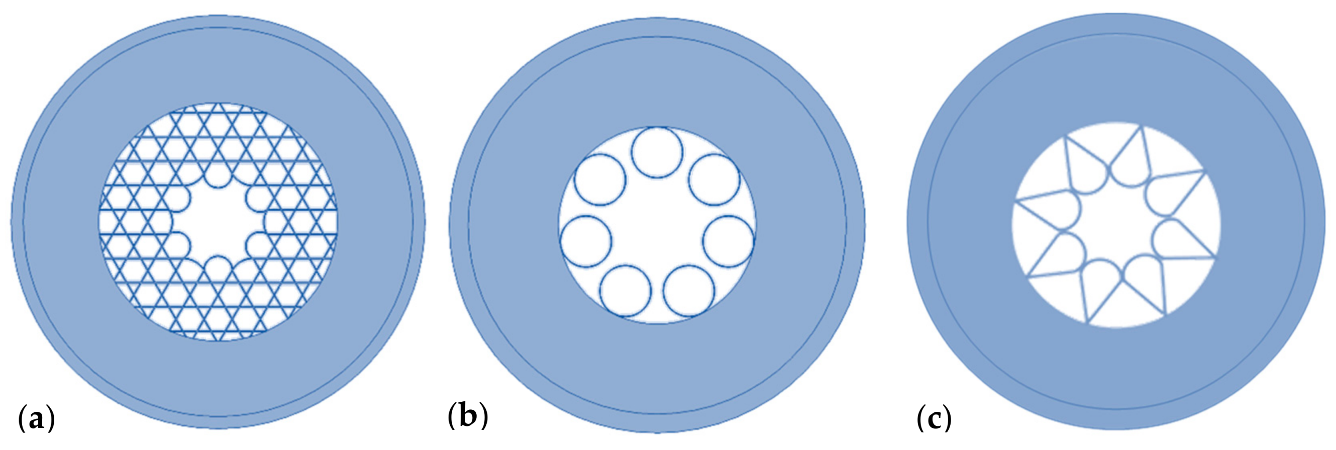
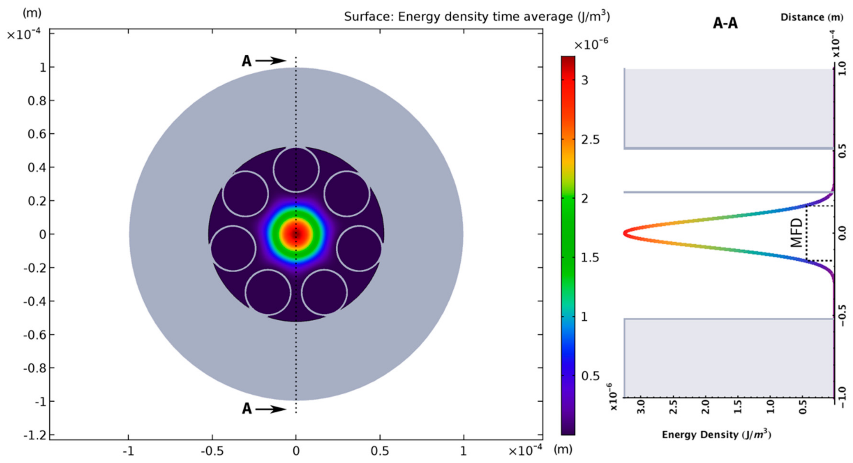
2.1. Types of Fibers
2.2. Limitations of the Technology
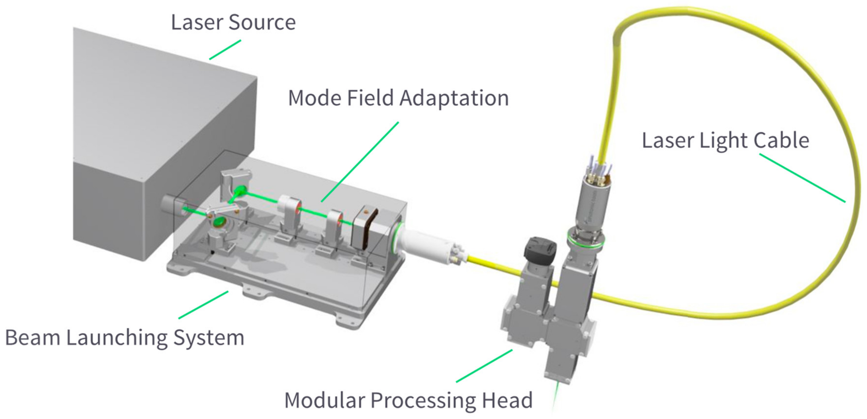
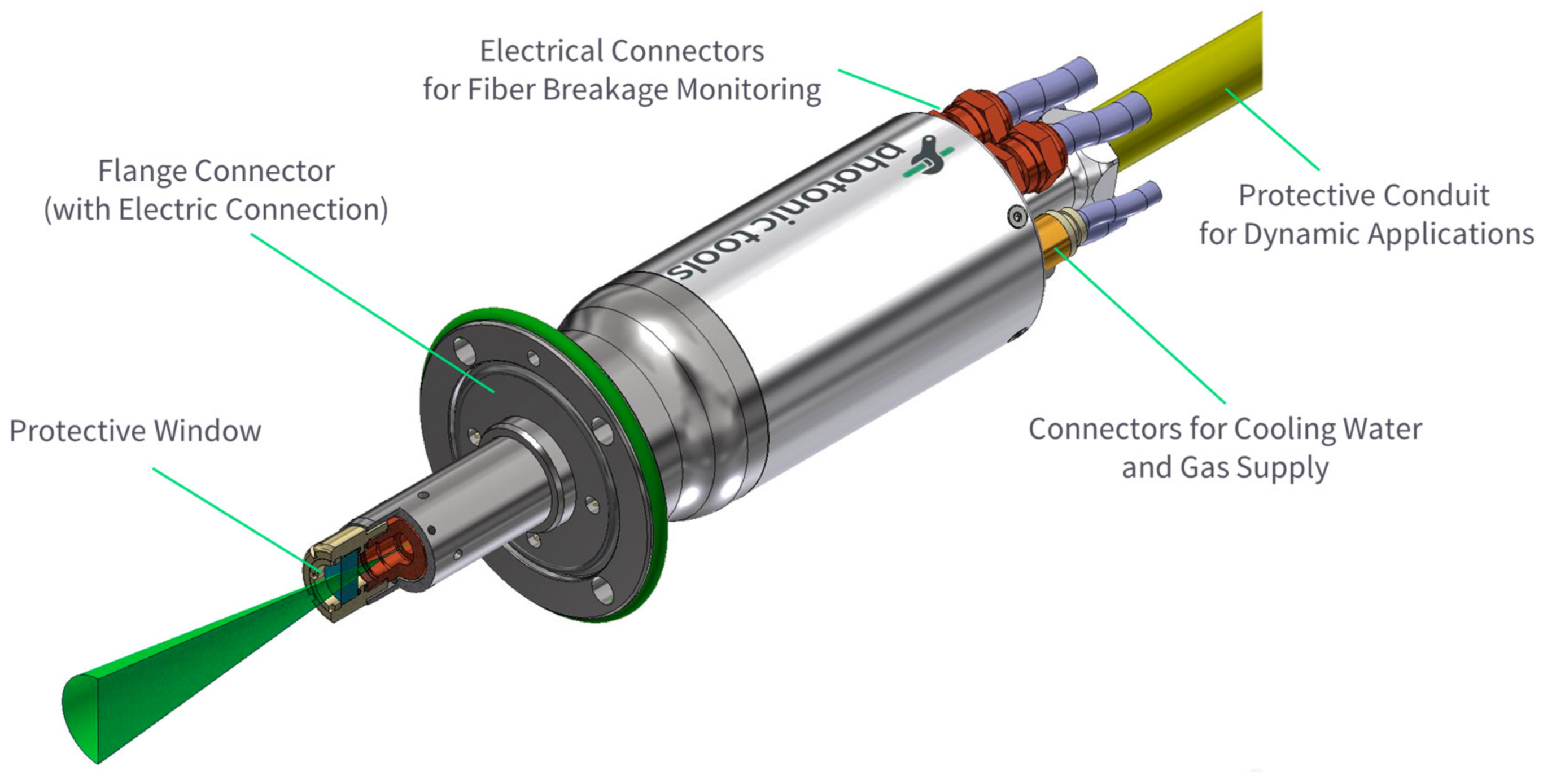
2.3. Fiber Integration
3. Results
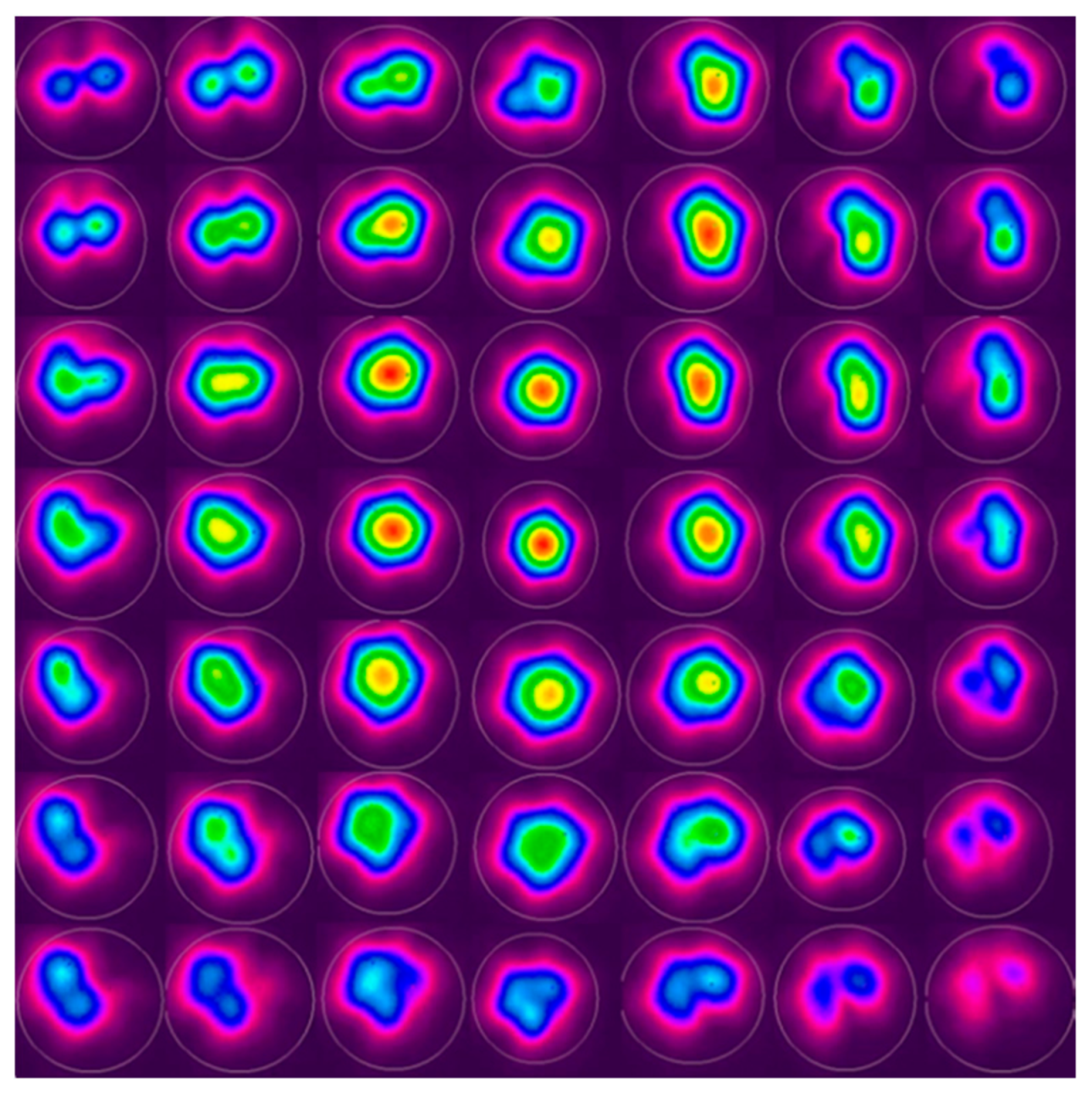
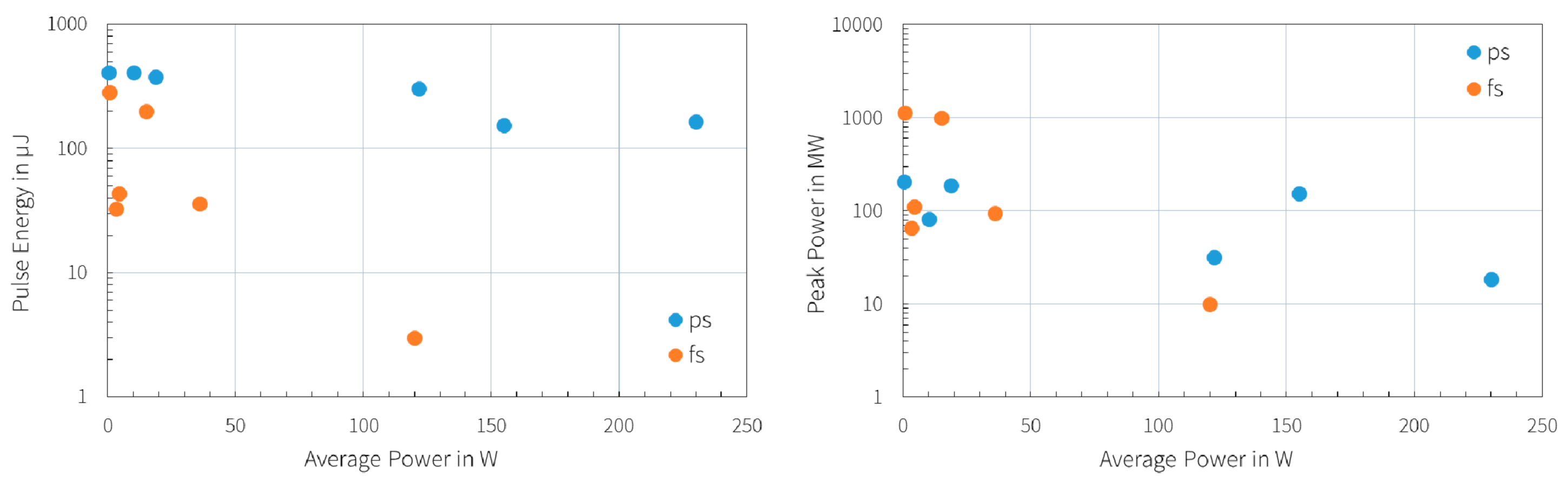
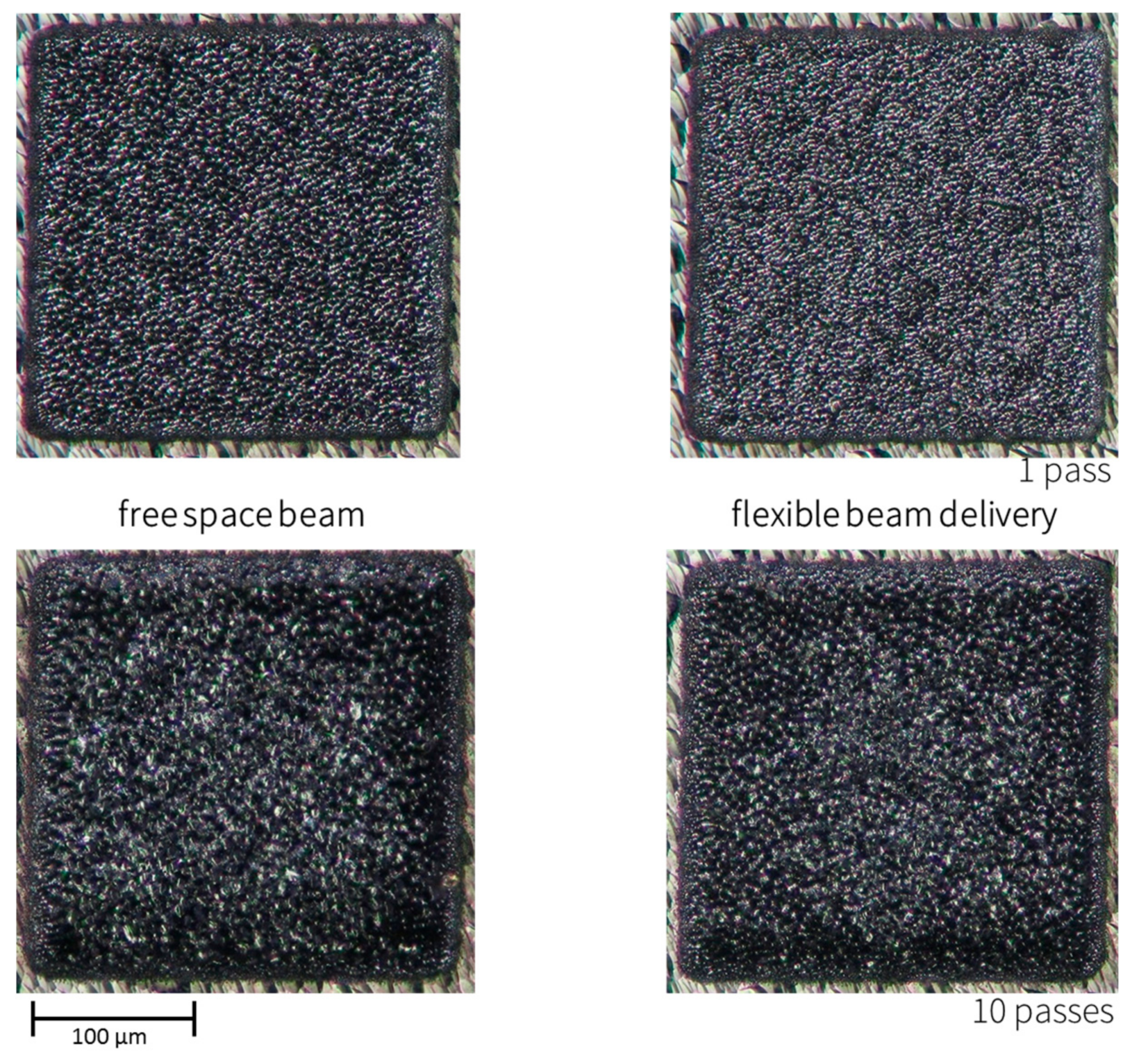
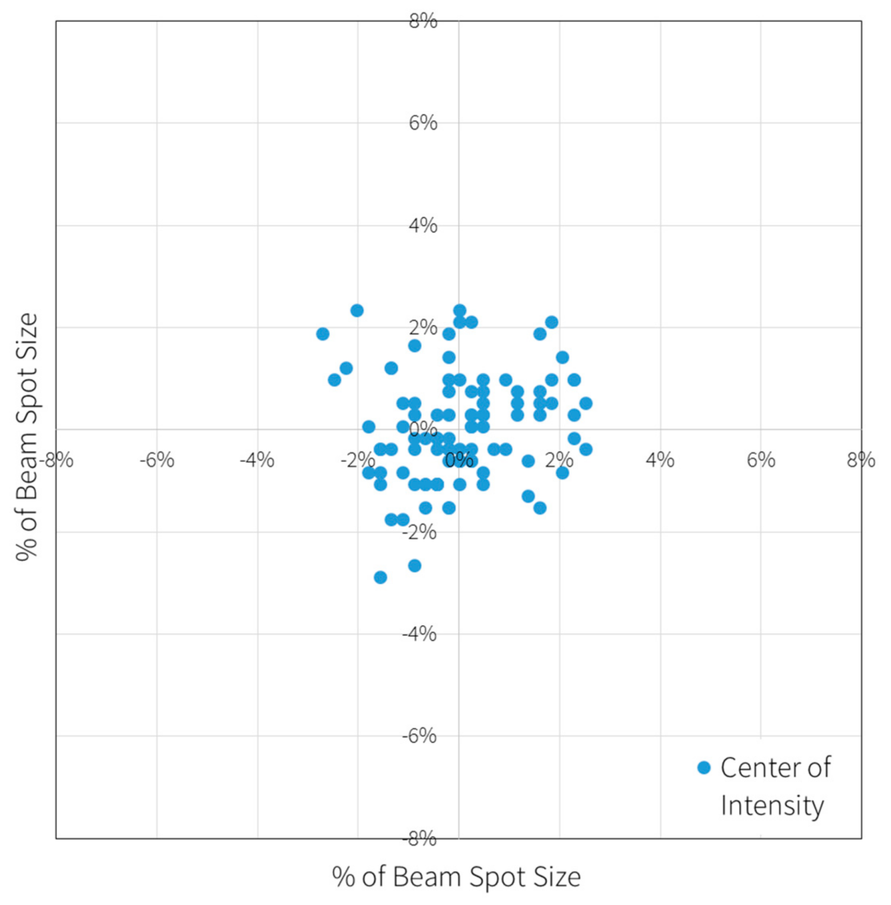
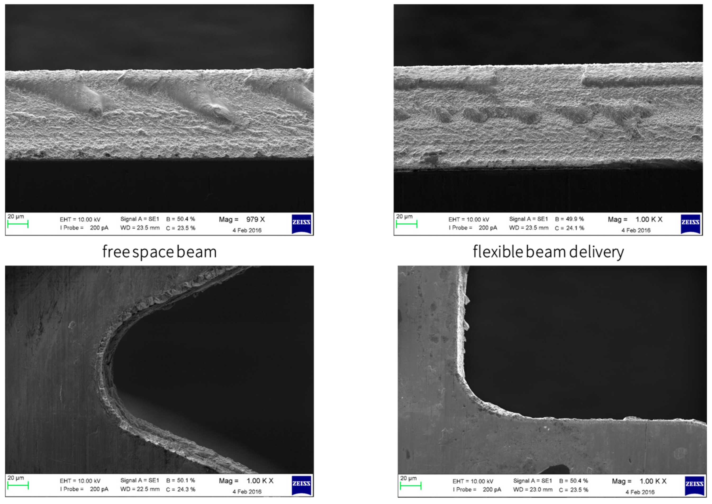
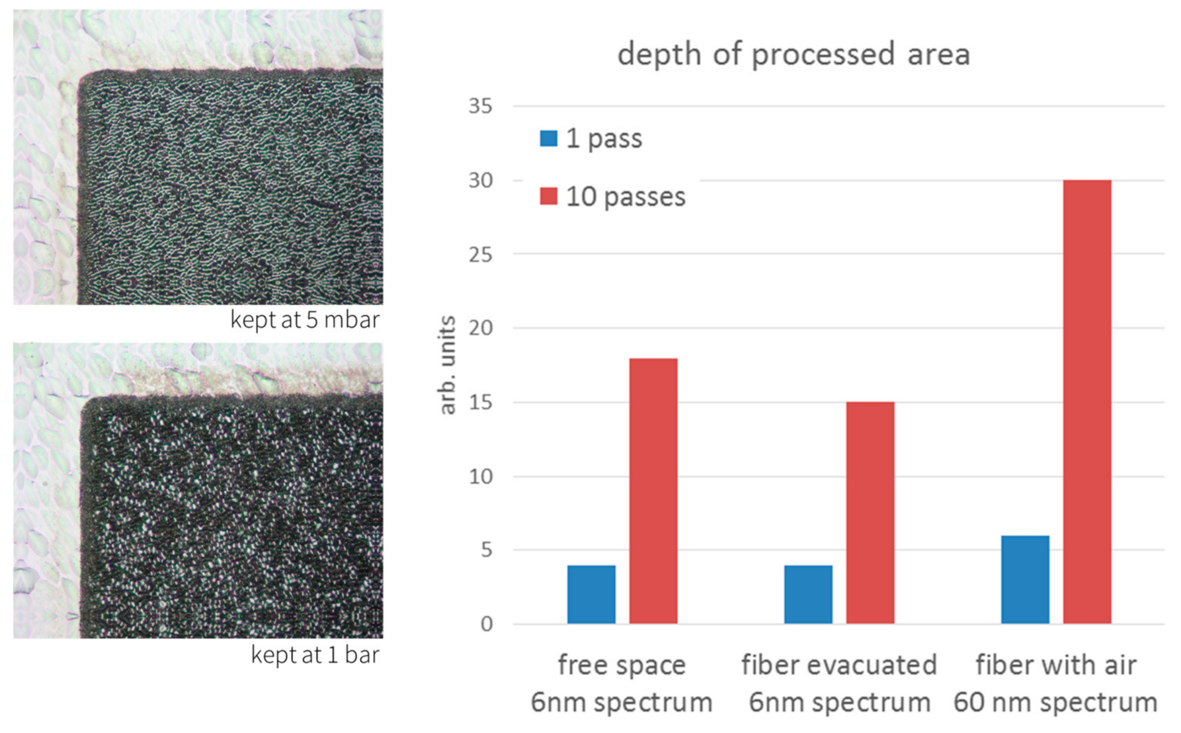
3.1. Performance
3.2. Application
4. Conclusions
Author Contributions
Funding
Acknowledgments
Conflicts of Interest
References
- Sugioka, K.; Cheng, Y. Ultrafast lasers—Reliable tools for advanced materials processing. Light Sci. Appl. 2014, 3, e149. [Google Scholar] [CrossRef]
- Cregan, R.F.; Mangan, B.J.; Knight, J.C.; Birks, T.A.; Russell, P.S.J.; Roberts, P.J.; Allan, D.C. Single-mode photonic band gap guidance of light in air. Science 1999, 285, 1537–1539. [Google Scholar] [CrossRef] [PubMed]
- Debord, B.; Alharbi, M.; Bradley, T.; Fourcade-Dutin, C.; Wang, Y.Y.; Vincetti, L.; Gérôme, F.; Benabid, F. Hypocycloid-shaped hollow-core photonic crystal fiber part I: Arc curvature effect on confinement loss. Opt. Express 2013, 21, 28597–28608. [Google Scholar] [CrossRef] [PubMed]
- Litchinitser, N.M.; Abeeluck, A.K.; Headley, C.; Eggleton, B.J. Antiresonant reflecting photonic crystal optical waveguides. Opt. Lett. 2002, 27, 1592–1594. [Google Scholar] [CrossRef] [PubMed]
- Yu, F.; Knight, J.C. Spectral attenuation limits of silica hollow core negative curvature fiber. Opt. Express 2013, 22, 21466–21471. [Google Scholar] [CrossRef] [PubMed]
- Alharbi, M.; Bradley, T.; Debord, B.; Fourcade-Dutin, C.; Ghosh, D.; Vincetti, L.; Gérôme, F.; Benabid, F. Hypocycloid-shaped hollow-core photonic crystal fiber Part II: Cladding effect on confinement and bend loss. Opt. Express 2013, 21, 28609–28616. [Google Scholar] [CrossRef] [PubMed]
- Finger, M.A.; Joly, N.Y.; Weiss, T.; Russell, P.S.J. Accuracy oft he capillary approximation for gas-filled kagomé-style photonic crystal fiber. Opt. Lett. 2014, 39, 821–824. [Google Scholar] [CrossRef] [PubMed]
- Carter, R.M.; Yu, F.; Wadsworth, W.J.; Shephard, J.D.; Birks, T.; Knight, J.C.; Hand, D.P. Measurement of resonant bend loss in anti-resonant hollow core optical fiber. Opt. Express 2017, 25, 20612–20621. [Google Scholar] [CrossRef] [PubMed]
- Michieletto, M.; Lyngsø, J.K.; Jakobsen, C.; Lægsgaard, J.; Bang, O.; Alkeskjold, T.T. Hollow-core fibers for high power pulse delivery. Opt. Express 2016, 24, 7103–7119. [Google Scholar] [CrossRef] [PubMed]
- Ermolov, A.; Mak, K.F.; Frosz, M.H.; Travers, J.C.; Russell, P.S.J. Supercontinuum generation in the vacuum ultraviolet through dispersive-wave and soliton-plasma interatction in a noble-gas-filled hollow-core photonic crystal fiber. Phys. Rev. A 2015, 92, 033821. [Google Scholar] [CrossRef]
- Benabid, F.; Knight, J.C.; Antonopoulos, G.; Russell, P.S.J. Stimulated raman scattering in hydrogen-filled hollow-core photonic crystal fiber. Science 2002, 298, 399–402. [Google Scholar] [CrossRef] [PubMed]
- Smith, A.V.; Do, B.T.; Hadley, G.R.; Farrow, R.L. Optical damage limits to pulse energy from fibers. IEEE J. Sel. Top. Quantum Electron. 2009, 15, 153–158. [Google Scholar] [CrossRef]
- Bhagwat, A.R.; Gaeta, A.L. Nonlinear optics in hollow-core photonic bandgap fibers. Opt. Express 2008, 16, 5035–5047. [Google Scholar] [CrossRef] [PubMed]
- Chang, W.; Nazarkin, A.; Travers, J.C.; Nold, J.; Hölzer, P.; Joly, N.Y.; Russell, P.S.J. Influence of ionizsation on ultrafast gas-based nonlinear fiber optics. Opt. Express 2011, 19, 21018–21027. [Google Scholar] [CrossRef] [PubMed]
- Mousavi, S.A.; Mulvad, H.C.H.; Wheeler, N.V.; Horak, P.; Hayes, J.; Chen, Y.; Bradley, T.D.; Alam, S.; Sandoghchi, S.R.; Richardson, D.J.; et al. Nonlinear dynamic of picosecond pulse propagation in atmospheric air-filled hollow core fibers. Opt. Express 2018, 26, 8866–8882. [Google Scholar] [CrossRef] [PubMed]
- Funck, M.C.; Eilzer, S.; Wedel, B. Ultrafast beam delivery: System technology and industrial application. In Proceedings of the High-Power Laser Materials Processing: Applications, Diagnostics, and Systems VI, San Francisco, CA, USA, 28 January–2 February 2017; p. 100970L. [Google Scholar]


| Parameters | Value | Unit |
|---|---|---|
| Laser source | Amplitude Satsuma | |
| Pulse length | 350 | fs |
| Power | 5 | W |
| Repetition rate | 0–2 | MHz |
| Beam delivery | Photonic Tools | |
| LLK length | 3 | m |
| Collimation | 100 | mm |
| Air pressue in fiber | 5–1000 | mbar |
| Workpiece | Nitinol | |
| Wavelength | 1030 | nm |
| Polarization | circular | |
| Repetition rate | 300 | kHz |
| Pulse energy | ~8 | µJ |
| Spot size | ~12 | µm |
| Parameters | Value | Unit |
|---|---|---|
| Laser source | Amplitude S-Pulse | |
| Pulse length | 750 | fs |
| Power | 4 | W |
| Repetition rate | 0–300 | kHz |
| Beam delivery | Photonic Tools | |
| LLK length | 2.5 | m |
| Collimation | 100 | mm |
| Air pressue in fiber | 5–1000 | mbar |
| Workpiece | Polycrystalline silicon | |
| Wavelength | 1028 ± 3 1030 ± 30 | nm |
| Polarization | linear | |
| Repetition rate | 100 | kHz |
| Pulse energy | 12.5 | µJ |
| Spot size | 16 | µm |
| Scan speed | 4 | mm/s |
© 2018 by the authors. Licensee MDPI, Basel, Switzerland. This article is an open access article distributed under the terms and conditions of the Creative Commons Attribution (CC BY) license (http://creativecommons.org/licenses/by/4.0/).
Share and Cite
Eilzer, S.; Wedel, B. Hollow Core Optical Fibers for Industrial Ultra Short Pulse Laser Beam Delivery Applications. Fibers 2018, 6, 80. https://doi.org/10.3390/fib6040080
Eilzer S, Wedel B. Hollow Core Optical Fibers for Industrial Ultra Short Pulse Laser Beam Delivery Applications. Fibers. 2018; 6(4):80. https://doi.org/10.3390/fib6040080
Chicago/Turabian StyleEilzer, Sebastian, and Björn Wedel. 2018. "Hollow Core Optical Fibers for Industrial Ultra Short Pulse Laser Beam Delivery Applications" Fibers 6, no. 4: 80. https://doi.org/10.3390/fib6040080
APA StyleEilzer, S., & Wedel, B. (2018). Hollow Core Optical Fibers for Industrial Ultra Short Pulse Laser Beam Delivery Applications. Fibers, 6(4), 80. https://doi.org/10.3390/fib6040080