1. Introduction
In recent years, fiber-reinforced polymer composites have become widely adopted in transportation engineering due to their high specific stiffness and strength, as well as their superior fatigue and corrosion resistance [
1,
2,
3,
4,
5]. Their ability to provide significant weight reduction while maintaining structural performance has made them particularly attractive for lightweight airframe structures. This trend is especially visible in the rapidly expanding sector of unmanned aerial vehicles (UAVs), where structural efficiency directly translates into extended flight time, increased payload capacity, and improved operational range [
6,
7]. Recent research trends in lightweight aerospace structures have also included sustainable and hybrid composite materials with enhanced vibration damping capabilities.
A large share of small- and medium-scale UAV structures is produced using manual composite manufacturing techniques, with hand lay-up being one of the most commonly applied methods [
2,
8,
9]. Its popularity stems from low implementation cost, minimal equipment requirements, and adaptability to prototype and limited-series production. Nevertheless, the process relies heavily on operator precision and does not inherently ensure strict control over ply alignment [
10].
Even small deviations in fiber orientation can lead to measurable changes in the structural response of carbon fiber-reinforced polymer (CFRP) laminates. Due to the inherently orthotropic nature of carbon fiber plies, their mechanical properties are strongly direction-dependent, with stiffness and strength predominantly governed by fiber alignment [
11,
12]. As a result, any variation in ply angle modifies the effective laminate stiffness matrices, potentially affecting bending rigidity, deformation patterns, and coupling behavior in non-symmetric stacking sequences.
Alterations in stiffness directly influence both static and dynamic characteristics of slender aerospace structures. Changes in bending stiffness affect deflections under aerodynamic loading, while variations in the mass–stiffness distribution modify natural frequencies and modal shapes. This sensitivity is particularly relevant in modern UAV configurations, where lightweight design and high aspect ratio wings increase structural flexibility [
13,
14]. In such systems, even moderate stiffness variations may contribute to larger deflections and enhanced geometric nonlinear effects, which are challenging to capture accurately in predictive models [
15,
16].
From an aeroelastic standpoint, reliable prediction of flutter and other dynamic instabilities depends on accurate structural input data. Contemporary aeroelastic analysis tools typically utilize modal parameters such as natural frequencies and mode shapes as key inputs [
17]. Since these quantities are directly linked to laminate stiffness, small deviations in fiber orientation may indirectly influence predicted aeroelastic stability margins and critical flutter speeds.
Given that manual lay-up may introduce unintended ply misalignment, there is a need to quantify how such deviations influence structural characteristics relevant to UAV wing performance. In practical engineering environments, particularly in small-scale or cost-sensitive UAV production, extensive material characterization campaigns are often impractical. Standardized mechanical testing procedures, such as tensile testing according to ASTM D3039, require dedicated equipment, controlled laboratory conditions, and significant experimental effort. While such methods provide valuable material-level data, they are not always directly applicable as rapid verification tools during early-stage structural assessment.
Wang et al. [
18] investigated the influence of fiber orientation on Young’s modulus for unidirectional glass fiber reinforced polymer through analytical, numerical, and experimental approaches. A U-shaped dependency of the Young’s modulus of composites on the inclined angle of fiber was found. Patel and Dave [
19] analyzed effect of fiber orientation on tensile strength of thin composites made of bi-directional carbon fiber. Authors used three orientations of specimens: [0°/90°], [30°/−60°] and [45°/−45°]. It was found that as the fiber orientation increases from 0° to 45°, there is a downward trend in tensile strength. Sarangapani and Ganguli [
20] investigated the influence of ply-level material property uncertainties on elastic coupling behavior in composite laminates using Monte Carlo simulations. It demonstrates that such uncertainties can introduce or significantly modify coupling effects—even in laminates designed to be uncoupled—leading to unintended strains and curvatures and highlighting the importance of accounting for these variations during the design stage. Franz et al. [
21] investigated the effect of ply misalignment in material characterization of composite laminates through numerical and experimental tensile test using unidirectional carbon fiber composites with deliberately planned fiber angles arranged at 5 and 10 degrees. The study highlighted the need for good variation management in composite structures by investigating different small artificially induced fiber orientation variations. Recent research trends in lightweight aerospace structures have also included sustainable and hybrid composite materials with enhanced vibration damping capabilities [
22,
23]. Cork-based composite laminates have been investigated as environmentally friendly alternatives for lightweight sandwich and laminated structures, demonstrating favorable dynamic response and vibration attenuation properties relevant to aerospace and UAV applications [
24].
For lightweight UAV structures, global structural parameters such as bending stiffness and natural frequencies are of primary importance, as they directly relate to deformation under aerodynamic loading and dynamic response. Therefore, this study explores application-oriented experimental approaches, including cantilever bending tests and experimental modal analysis, as practical alternatives for detecting stiffness variations associated with small ply angle deviations. These methods are compared with finite element model in order to assess their capability to identify and quantify the structural impact of manufacturing-representative misalignment. The central objective of this work is to evaluate whether numerical models can reliably capture the influence of small ply angle offsets on the bending and modal response of CFRP laminates representative of UAV structural components. In particular, the study addresses the following research questions:
To what extent do small ply angle deviations affect key structural parameters relevant to UAV wings, such as bending deformation and natural frequencies?
Can a methodology provide sufficiently consistent and sensitive results for practical engineering assessment?
Is a finite element model capable of accurately predicting these effects, thereby supporting increased reliance on simulation-based validation in place of extensive experimental campaigns?
By answering these questions, the study aims to contribute to improved confidence in numerical modeling of composite UAV structures while proposing experimentally accessible methods for assessing manufacturing-induced variability. Although Franz et al. [
21] addressed a similar issue of fiber misalignment, their study focused on unidirectional laminates and standard tensile testing. In contrast, the present work considers laminate-level behavior under bending and dynamic loading conditions, which are more representative of real UAV structural applications. Furthermore, this study evaluates the potential of these non-destructive techniques as a quality control tool in the manufacturing of small-scale UAV components, where verifying the internal ply alignment is otherwise difficult without specialized imaging equipment. Since aerospace sector requires exceptionally high safety and reliability standards, both in terms of flight operations and structural integrity, due to the stringent regulatory requirements associated with air transport systems [
25] reliable prediction of structural behavior is essential, making the accuracy and credibility of numerical models particularly important during the design and verification process of aerospace structures.
2. Materials and Methods
To investigate the influence of small ply angle deviations on the structural response of composite laminates representative of UAV components, a combined numerical and experimental methodology was adopted. The study focuses on laminate configurations manufactured using a manual hand lay-up process, in which minor variations in fiber alignment may occur due to the inherent characteristics of the technique. Rather than attempting to completely eliminate this variability, the methodology aims to evaluate how such deviations may affect structural parameters relevant to slender aerospace structures.
The experimental investigation is based on composite laminates manufactured with intentionally introduced ply orientation offsets in order to reproduce potential deviations that may occur during manual fabrication. Beam-type specimens were selected for testing, as this geometry provides a simplified structural representation of slender lifting components such as composite UAV wings. Such structures are typically characterized by significant bending deformation and dynamic behavior that directly influence their aeroelastic performance.
Two types of experimental tests were conducted: experimental modal analysis and cantilever bending tests. The cantilever configuration was chosen to approximate the boundary conditions experienced by aircraft wings, which are effectively fixed at the root and free along the span. This setup enables the evaluation of both structural deformation and natural vibration characteristics under conditions representative of slender aerospace structures. Determining both the deformation response and the natural frequencies of the specimens is particularly important, as these parameters directly influence aeroelastic phenomena. Modal properties, including natural frequencies and mode shapes, constitute essential input data for aeroelastic analyses used to predict dynamic instabilities such as flutter [
26]. Inaccurate structural parameters may therefore lead to incorrect predictions of aeroelastic stability limits.
Since the orientation of composite fibers strongly governs laminate stiffness, even small variations in ply angle may alter both the deformation response and modal characteristics of the structure. For this reason, understanding the sensitivity of these parameters to small orientation deviations is essential when evaluating the structural behavior of manually manufactured composite components.
In addition to the experimental investigation, numerical simulations were performed to assess whether a finite element model incorporating the directional properties of composite plies is capable of capturing the influence of such deviations. The numerical modal analysis included the explicit definition of ply orientation in order to reproduce the tested laminate configurations. Comparing the experimentally measured modal properties and bending deformations with the numerical predictions allows the reliability of the simulation approach to be evaluated.
This aspect is particularly relevant for small-scale UAV manufacturers, for whom extensive experimental campaigns or specialized mechanical testing infrastructure may be impractical. If the numerical model proves capable of accurately capturing the structural effects associated with small ply orientation deviations, it may serve as a practical alternative for assessing structural variability without the need for costly experimental testing.
2.1. Laminate Design
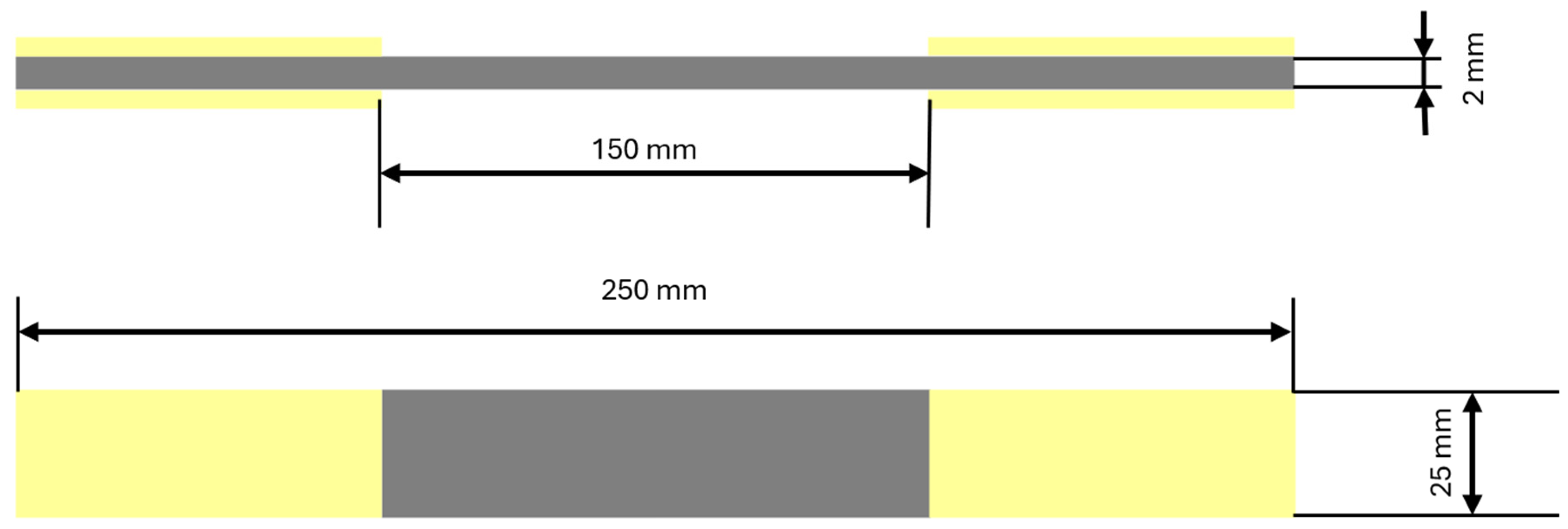
Specimens used in this study were designed with a geometry corresponding to that typically employed in tensile tests according to ASTM D3039 [
27] (
Figure 1). Such a geometry provides a slender beam configuration that is suitable not only for tensile testing but also for cantilever bending and experimental modal analysis. In addition, this specimen shape enables relatively simple and repeatable fabrication of composite laminates, which is advantageous when multiple configurations must be manufactured for comparative analysis.
The specimens were manufactured using carbon fiber fabric Aspro A-80 carbon fabric with an areal weight of 80 g/m
2. This material is commonly used in the fabrication of lightweight UAV structures, particularly wings, due to its low weight and favorable mechanical properties. Furthermore, its mechanical characteristics have been previously investigated in earlier studies [
28], and the material parameters used in the present work are summarized in
Table 1. The laminates were impregnated using the aerospace-grade epoxy resin LG 285 epoxy resin, which is widely applied in manual composite manufacturing processes.
In order to obtain a laminate thickness comparable to the specimens used in the ASTM D3039 standard (approximately 2 mm), a stacking sequence consisting of 16 layers was selected. Considering that the nominal thickness of a single carbon fabric layer is approximately 0.12 mm, this configuration allows the target laminate thickness to be achieved while maintaining structural consistency across all tested configurations.
Three different laminate configurations were designed and manufactured, with three specimens prepared for each configuration. The first configuration served as the reference laminate and consisted of layers oriented in the 0/90° direction, representing a properly aligned laminate typical for composite UAV structures. The second and third configurations incorporated intentional deviations in ply orientation, with selected layers oriented at 5° and 10°, respectively. These deviations were introduced to simulate potential fiber misalignment that may occur during manual hand lay-up manufacturing.
Although a deviation of 10° represents a relatively large misalignment that may occur less frequently in practice, it was intentionally included to amplify the structural effects and allow clearer observation of the influence of fiber orientation errors on the structural response. It should also be noted that the laminates were intentionally designed as non-symmetric stacking sequences. This choice reflects the practical conditions of manual laminate fabrication, where fiber misalignment may occur in any layer and therefore influence the overall structural behavior of the laminate. The investigated laminate stacking sequences are summarized in
Table 2.
While typical fiber misalignment values reported in the literature are generally within the range of approximately 0.5° to 2° [
29,
30], the larger deviations considered in this study were intentionally considered in the present study in order to evaluate the sensitivity of the investigated structures to amplified manufacturing-induced variations. According to Franz et al. [
21], typical manufacturing variability may be represented using a normal distribution with a standard deviation ranging from approximately 0.5° to 2°, leading to a conformance range of approximately ±5° when considering ±3σ limits. Moreover, local fiber orientation deviations exceeding these values may occur due to manufacturing-related effects such as draping or manual handling during lay-up. Therefore, the selected 5° and 10° deviations were considered representative of an upper-bound and amplified variation range suitable for assessing the sensitivity and robustness of the numerical and experimental methodology.
2.2. Specimen Manufacturing and Preparation
The laminate manufacturing process began with cutting the required number of carbon fabric plies according to the orientations specified in the stacking sequences described in
Section 2.1. The cutting of individual layers was performed manually, reflecting typical fabrication practices used in small-scale composite manufacturing. Although manual cutting may introduce minor variations in fiber orientation, particular care was taken to maintain the intended alignment of the reinforcement layers. Any potential variability introduced during this stage was later considered when comparing the experimental results with the numerical predictions.
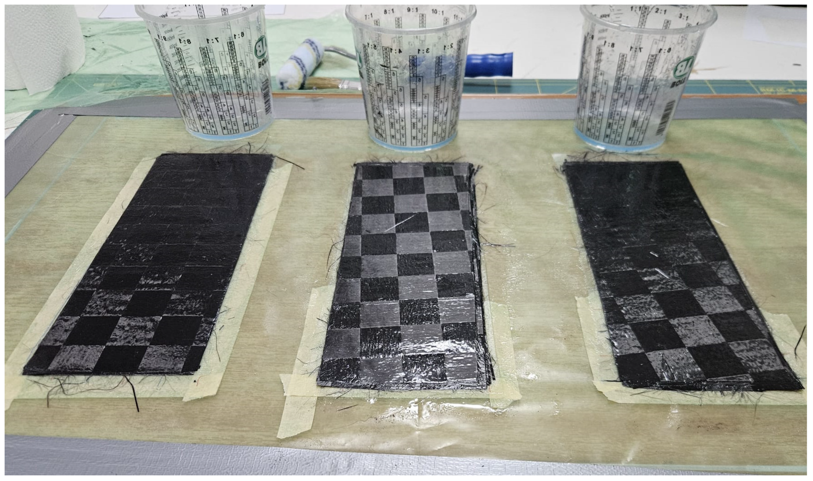
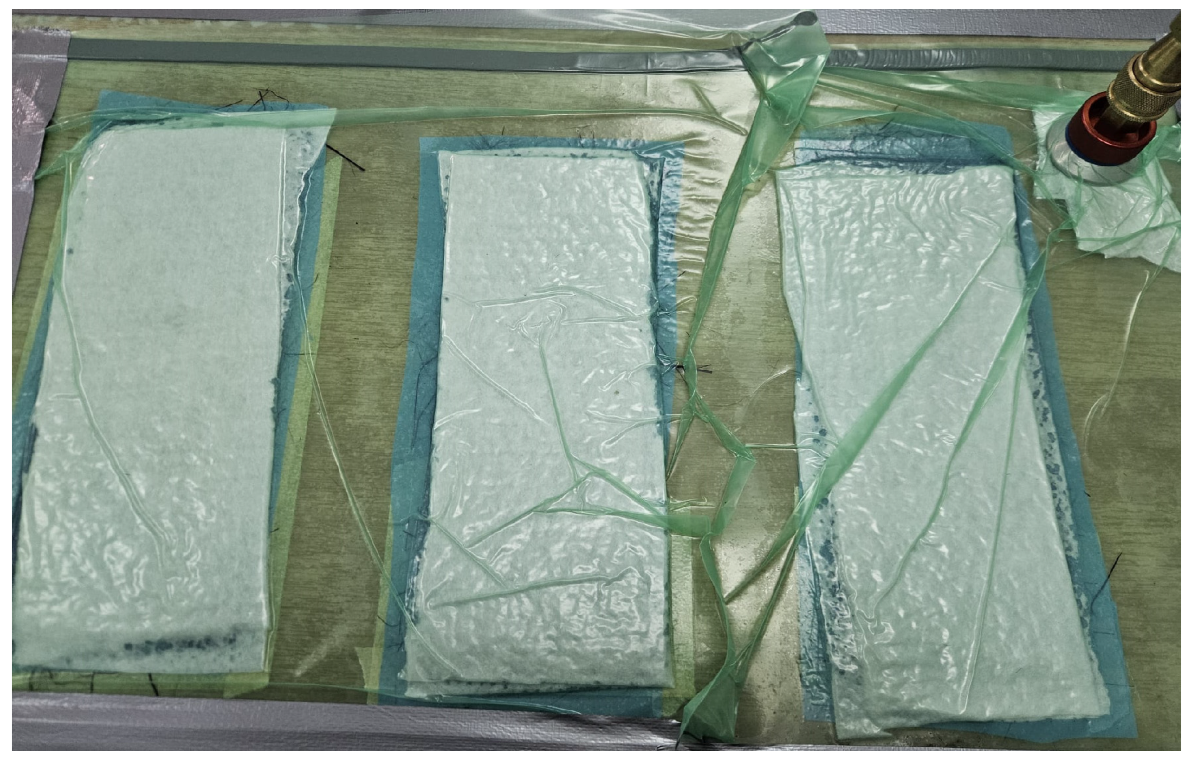
The laminates were fabricated on a flat mold surface using a manual hand lay-up technique. In order to ensure comparable conditions between the tested configurations, the same amount of resin was used for each laminate plate. The carbon fiber fabric layers were manually placed on the mold surface according to the stacking sequences defined in
Section 2.1. During lay-up, special attention was paid to maintaining the intended ply orientations. Reference alignment markings were applied to the mold surface in order to guide the positioning of individual fabric layers and introduce the designed angular deviations where required. Plates during process are shown in
Figure 2.
After completing the lay-up process, the laminates were consolidated using a vacuum bagging technique. All laminate plates were cured under identical conditions, including the same vacuum pressure, temperature, and curing time, in order to minimize process-induced variability between specimens. Samples under vacuum bag are shown in
Figure 3. After curing, the laminate plates were visually inspected to confirm proper consolidation and the absence of major manufacturing defects such as voids or delamination.
After curing, individual test specimens were extracted from each laminate plate using waterjet cutting in order to obtain beam-shaped samples with the geometry described in
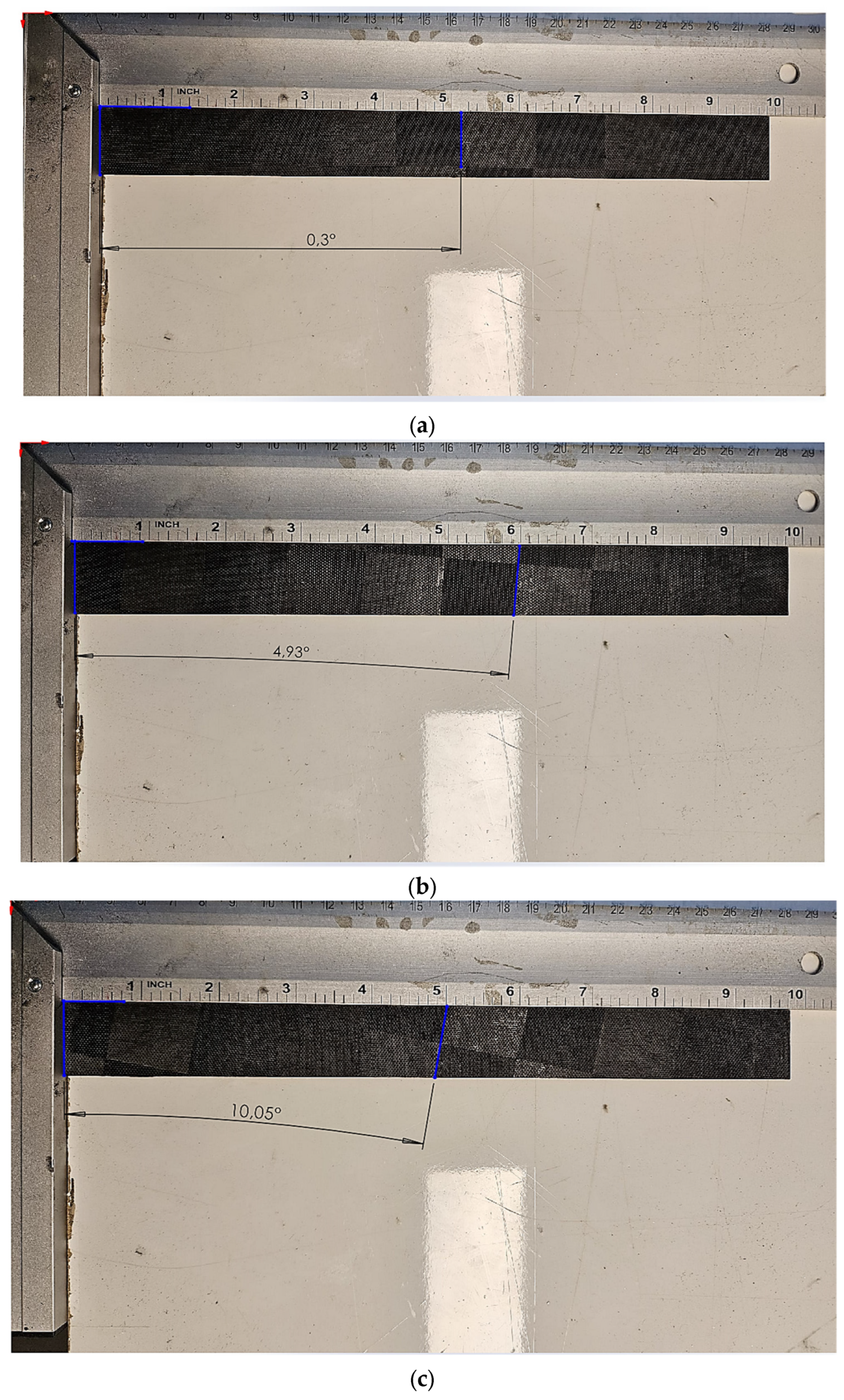
Section 2.1. For each laminate configuration, three specimens were prepared, resulting in a total of nine samples used in the experimental investigation. Due to the characteristic weave pattern of the carbon fiber fabric, the orientation of the outer ply could be visually identified without the need for specialized measurement techniques. This approach was used to verify the surface fiber orientation of the specimens, as illustrated in
Figure 4.
In this context, 3 specimens per configuration is justified by the fact that each set was derived from a single, identically manufactured laminate panel. This effectively reduces variability associated with batch-to-batch production differences, making the observed scatter primarily representative of local within-panel heterogeneities rather than broader manufacturing variability. Therefore, while the sample size is not intended for full statistical characterisation, it is considered sufficient for comparative assessment of configuration-dependent trends, which constitutes the primary objective of the study.
To ensure proper load transfer and prevent local damage during clamping in the test fixture, glass fiber tabs were bonded to the gripping sections of selected specimens. This solution allowed for more stable mounting during the experimental tests and reduced the risk of local crushing in the clamped region.
Prior to testing, the thickness of each specimen was measured in order to determine the effective laminate thickness and estimate the thickness of individual plies. These values were subsequently used as input parameters in the numerical model to ensure consistency between the experimental specimens and the finite element simulations. The measured thicknesses of the laminate specimens were 1.78 mm, 1.83 mm, and 1.76 mm, resulting in an average thickness of 1.79 mm. Based on the 16-ply stacking sequence, the corresponding average thickness of a single ply was determined to be approximately 0.112 mm.
2.3. Finite Element Model
Numerical simulations were performed in Ansys in order to evaluate the influence of ply angle deviations on both the modal characteristics and bending response of the investigated composite specimens.
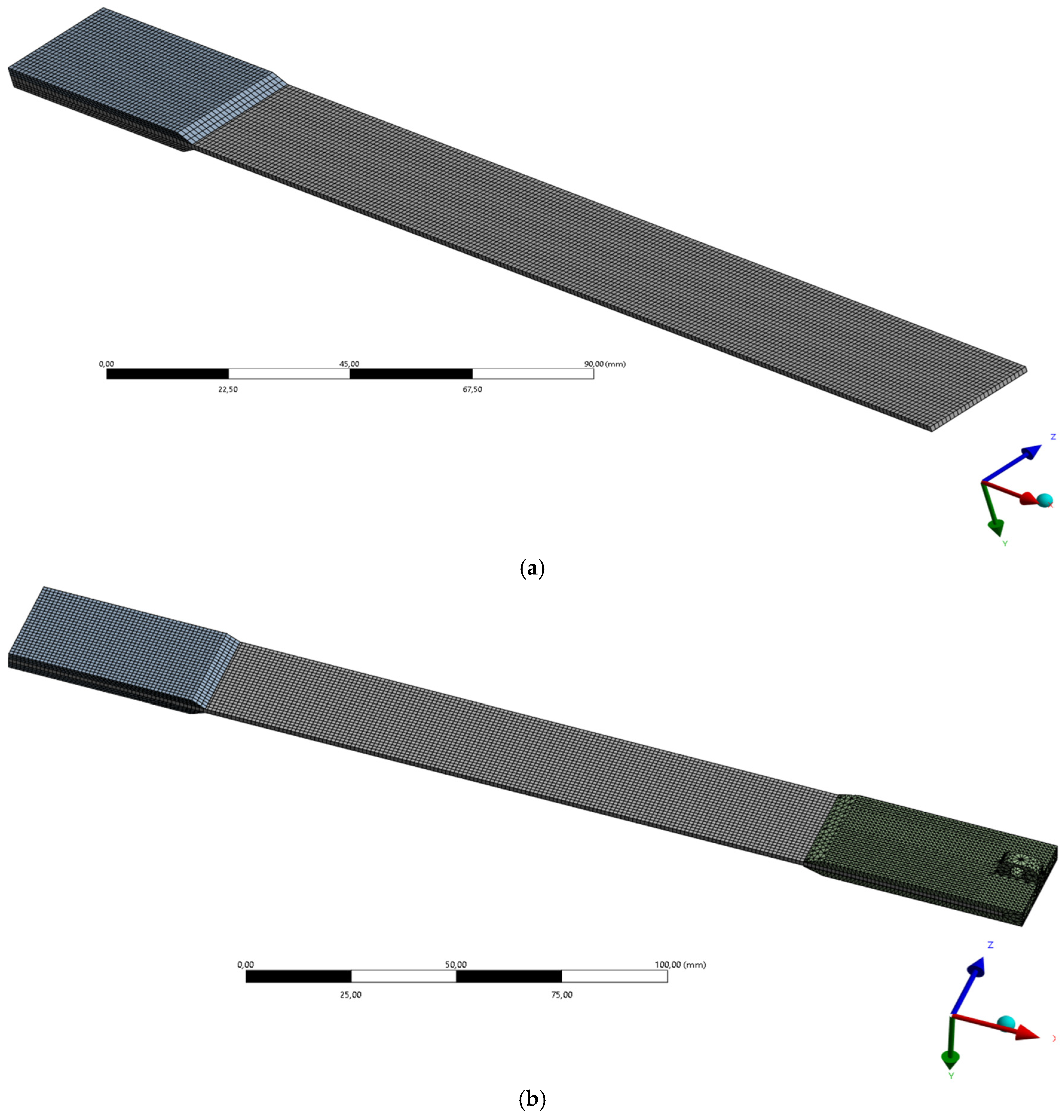
To accurately represent the layered composite structure, the laminate was modeled using the module Ansys Composite PrepPost (ACP). This module allows the laminate structure to be defined ply-by-ply with explicitly specified fiber orientations and thicknesses. The composite specimens were modeled using layered shell elements of type SHELL181. A uniform finite element mesh with an element size of 1 mm was applied to the laminate model. Considering the dimensions of the tested specimens, this mesh density was found to provide a sufficient level of accuracy for both deformation and modal response while maintaining reasonable computational efficiency.
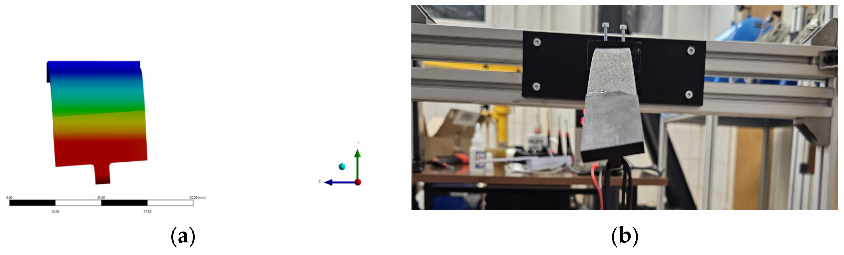
The composite tabs bonded to the fixed parts of the specimens were modeled using three-dimensional solid elements. These components were meshed using the same element size of 1 mm in order to maintain mesh compatibility with the shell elements representing the laminate (
Figure 5). The interaction between the laminate specimen and the tabs was modeled using a bonded contact formulation with a multi-point constraint (MPC) algorithm, which allows the bonded interface to be represented without relative motion between the connected surfaces. The model prepared in this way contained 6970 elements with an average quality of 0.95. For the bending simulations, the model was extended by including an additional solid component representing the loading element used in the experimental setup. The model for bending simulation contained 30,902 elements with an average quality of 0.9.
For the numerical simulation of the cantilever bending test, additional solid components representing the loading fixture elements used in the experimental setup were included in the model. These elements were also discretized using solid elements with a mesh size of 1 mm.
Boundary conditions were defined to reproduce the experimental test configuration. During the experimental investigations, the specimens were mounted in a clamped cantilever configuration without the possibility of movement in the fixed region. To replicate these conditions in the finite element model, the tabbed section of the specimen was defined as a fully fixed support. The same mounting procedure and clamping configuration were applied consistently for all tested specimens in order to improve repeatability and minimize variability associated with boundary conditions.
Two types of analyses were performed. First, a linear modal analysis was conducted to determine the natural frequencies and corresponding mode shapes of the specimens. No material or structural damping was included in the finite element model, as the objective of the numerical analysis was limited to the prediction of modal characteristics and global stiffness behavior under linear elastic assumptions. Subsequently, a static structural analysis was performed to evaluate the bending deformation of the cantilever beam under the applied load. The numerical results obtained from these simulations were later compared with the experimental measurements in order to assess the ability of the finite element model to capture the structural effects associated with small ply angle deviations.
2.4. Bending Test Bench
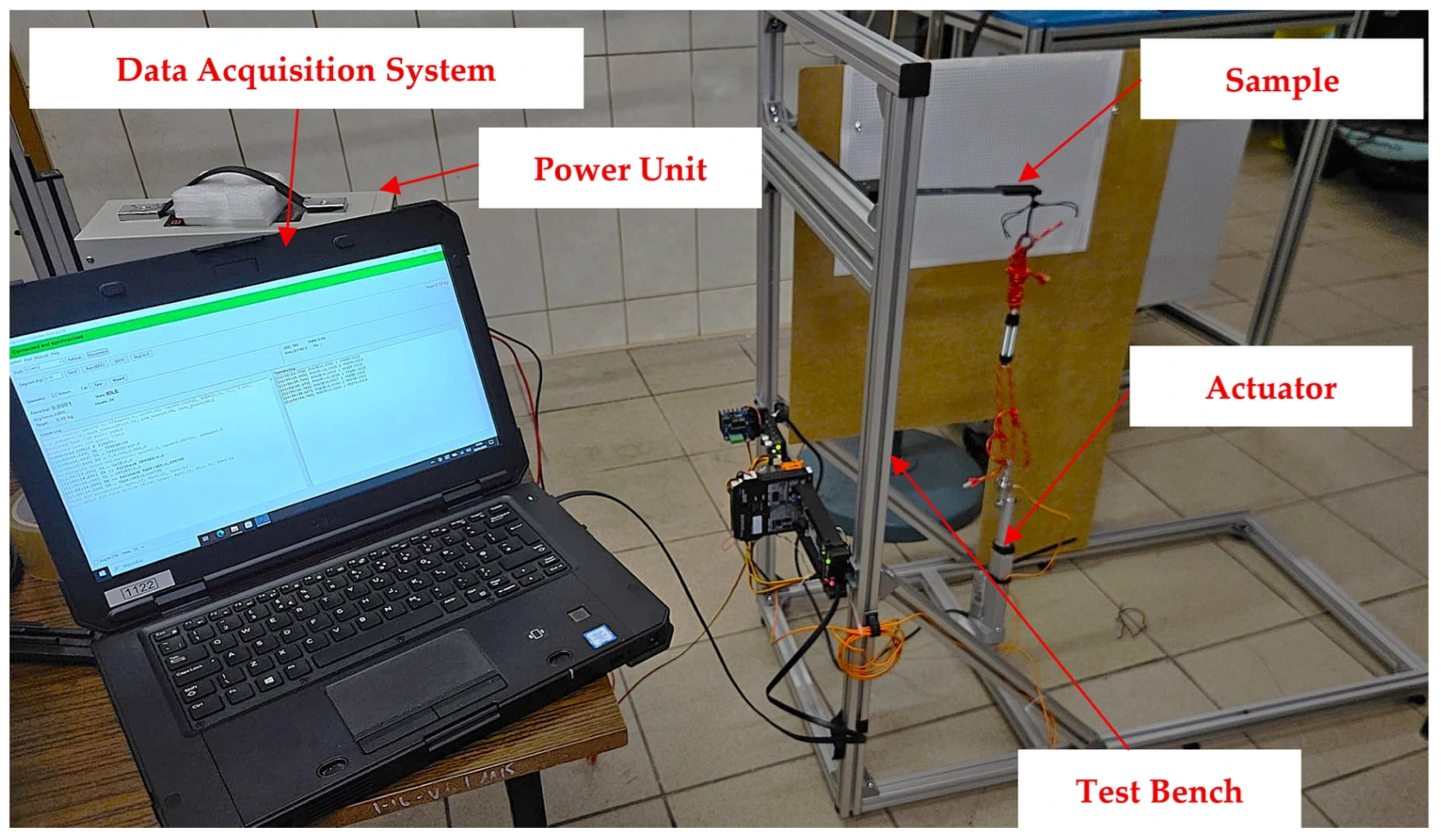
The bending tests were conducted using the experimental setup shown in
Figure 6. The test stand consisted of a rigid metal frame, an electric actuator, a fixture for mounting the specimens, and a data acquisition system.
The applied load was controlled using the measurement system and incrementally increased from 0 to 7 N in steps of 1 N. This load range was selected in order to avoid damage to the specimens while ensuring measurable deformation.
At each load increment, the position of the lower edge of the specimen was recorded relative to a fixed reference frame. The corresponding displacement was determined with respect to the initial (zero-load) position using a contact-based displacement measurement device with a resolution of 0.01 mm. The measurement procedure was repeated consistently for all specimens to ensure comparability of the results.
2.5. Modal Test Setup
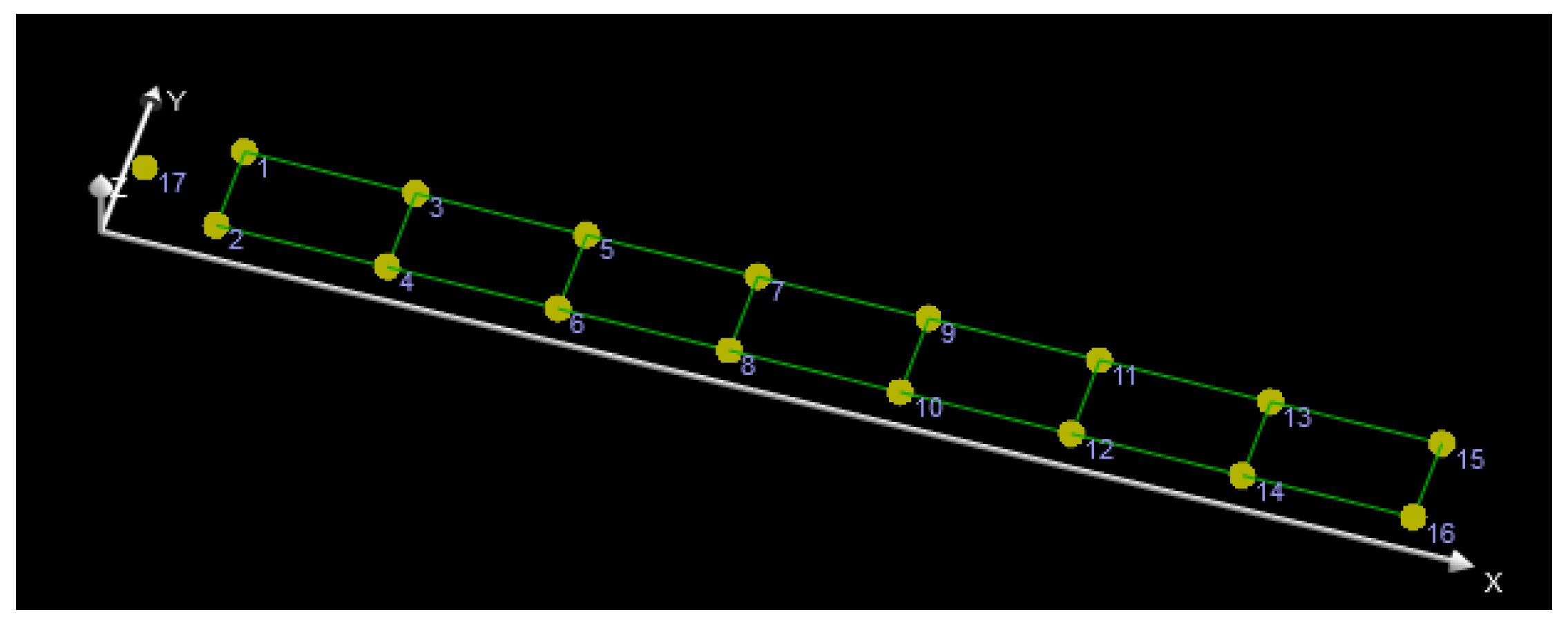
For the modal tests, a total of 16 measurement points were defined on each specimen, along with a single excitation point (
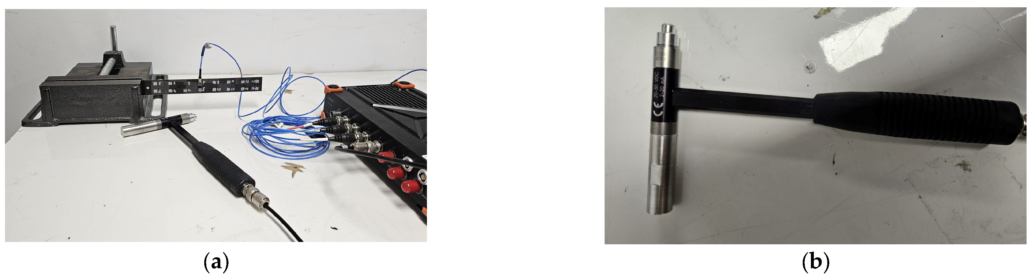
Figure 7).
The specimens were mounted in a cantilever configuration, with the fixed boundary condition applied at the end with tab (
Figure 8a). Excitation was introduced using an impact hammer equipped with a hard aluminum tip (
Figure 8b).
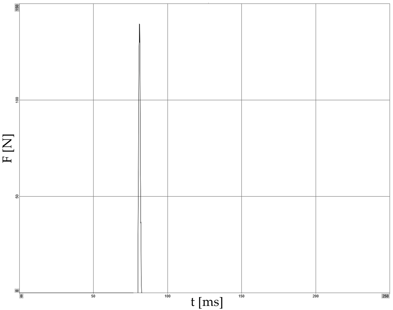
To ensure sufficient excitation energy, an additional 25 g mass was attached to the hammer. At each measurement location, three successive impacts were performed, and the resulting frequency response functions were averaged to improve the consistency and reliability of the identified modal parameters. The excitation impulse is shown in
Figure 9.
The structural response was measured using a miniature triaxial piezoelectric accelerometer. Due to the relatively low mass and high flexibility of the investigated specimens, the influence of the accelerometer mass on the identified modal parameters was also considered. The attached sensor locally altered the mass distribution of the structure and may have slightly affected the measured natural frequencies, particularly for the lower-order modes. Similar mass-loading effects have been reported in previous studies involving lightweight composite structures [
31]. The acquired force and acceleration signals were used to compute frequency response functions (FRFs), which formed the basis for modal parameter identification, including natural frequencies and mode shapes. The data acquisition was performed with a sampling frequency of 10 kHz, providing a frequency resolution of 0.5 Hz over 10,000 spectral lines, with a total acquisition time of 2 s. A force window was applied to the excitation signal to isolate the impact event, while no windowing was used for the response signals. All measurements were carried out under controlled laboratory conditions, with ambient temperature maintained at 22 ± 1 °C, relative humidity between 45% and 50%, and minimal environmental disturbances. During testing, coherence functions were continuously monitored to assess data quality. Measurements exhibiting coherence values below 0.95 within relevant frequency ranges were discarded and repeated.
3. Results
The following section presents and compares the results obtained from experimental testing and numerical simulations, including both cantilever bending tests and modal analysis.
3.1. Bending Test
The results of the bending tests are presented below. All nine specimens were subjected to bending, and the results are summarized in
Table 3,
Table 4 and
Table 5.
The
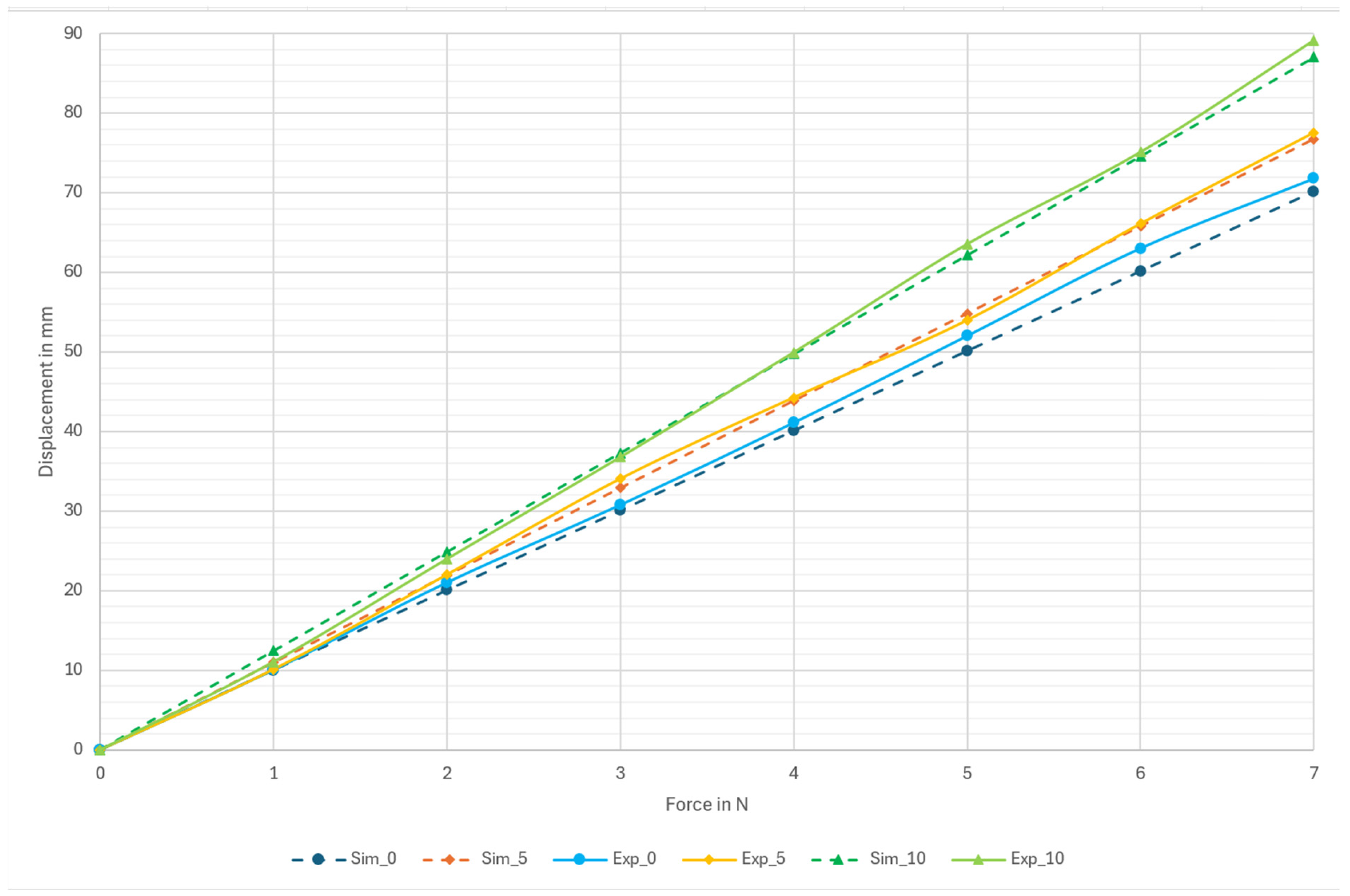
Figure 10 shows a comparison between the numerically predicted and experimentally measured force–displacement relationship, based on the average displacement obtained from the experimental specimens.
Figure 10.
Force–displacement for average displacement from experiment and simulation.
Figure 10.
Force–displacement for average displacement from experiment and simulation.
The numerical model demonstrated satisfactory agreement with the experimental results in terms of predicted deflections, indicating that the adopted modeling approach is capable of capturing the overall bending response of the investigated laminates. However, a slight tendency to overestimate the structural stiffness was observed, resulting in lower predicted deflections compared to the experimental measurements.
In addition, both the experimental observations and numerical simulations revealed a characteristic asymmetric deformation pattern for the L5 and L10 configurations shown in
Figure 11. This behavior manifested as a directional deflection of the specimen, with one edge exhibiting greater displacement than the other, particularly pronounced in the case of the L10 laminate at the maximum applied load.
3.2. Modal Analysis
The modal analysis was conducted to evaluate the influence of ply angle deviations on the dynamic response of the investigated composite laminates. Both experimental and numerical approaches were employed in order to determine the natural frequencies and corresponding mode shapes of the specimens.
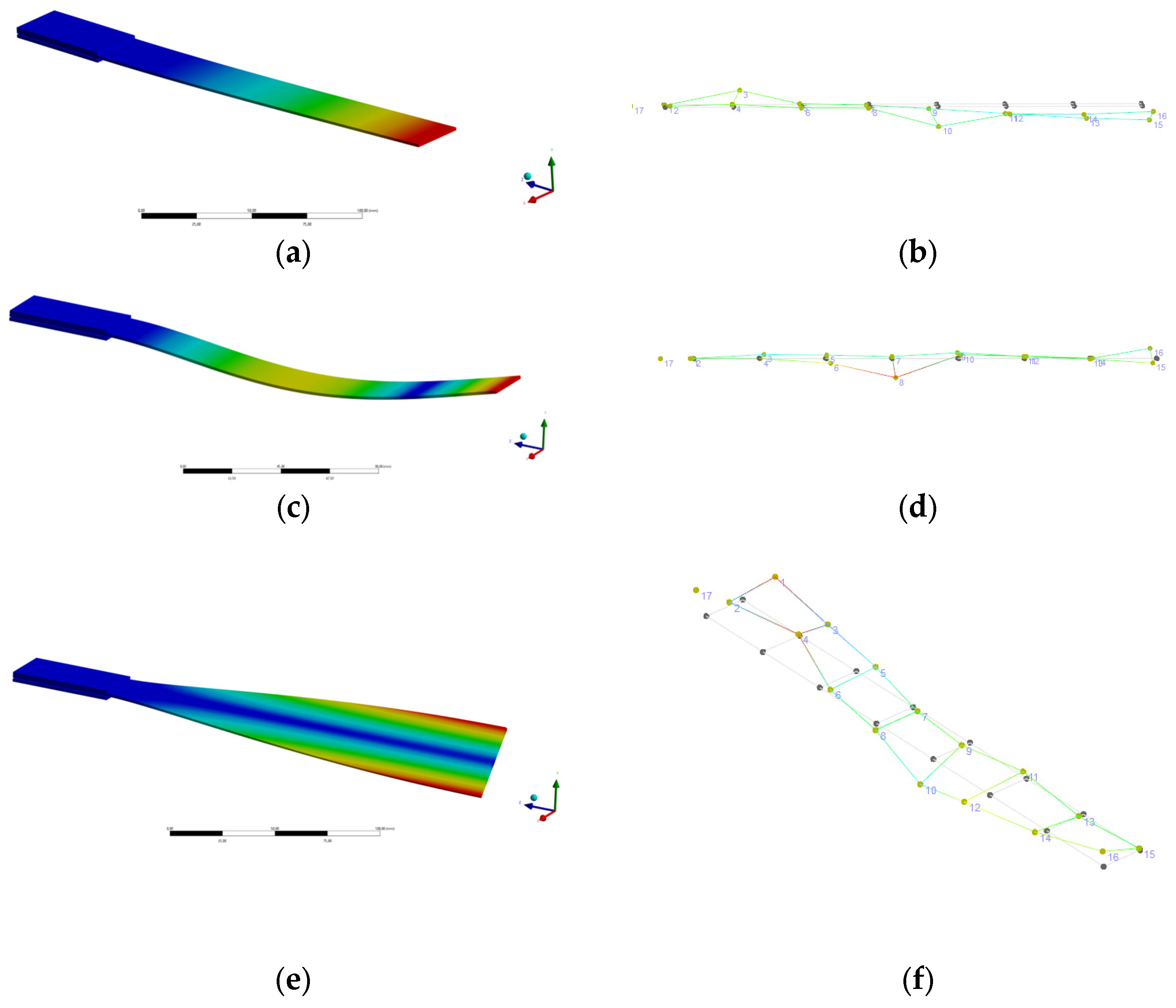
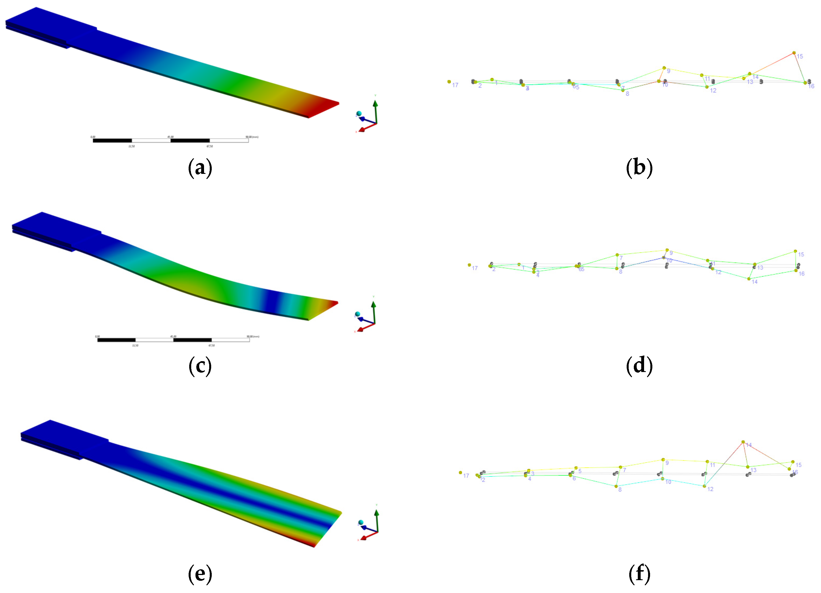
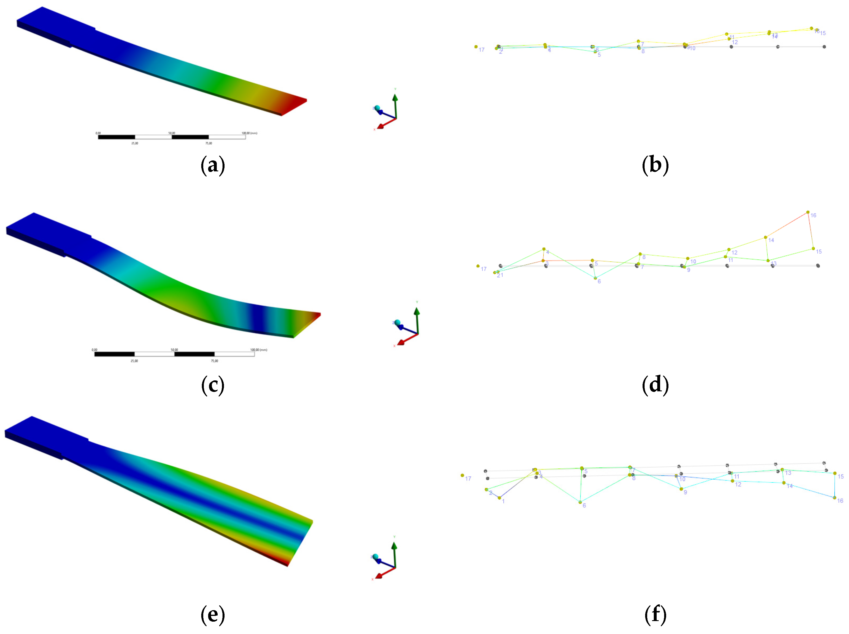
The identified mode shapes showed consistent characteristics across all tested laminate configurations (
Figure 12,
Figure 13 and
Figure 14), with no significant qualitative differences observed between the reference and modified specimens. The dominant deformation patterns were found to be similar for both experimental and numerical results. Only the first three mode shapes were considered, as from an aeroelastic standpoint the most relevant are the first bending and the first torsional modes.
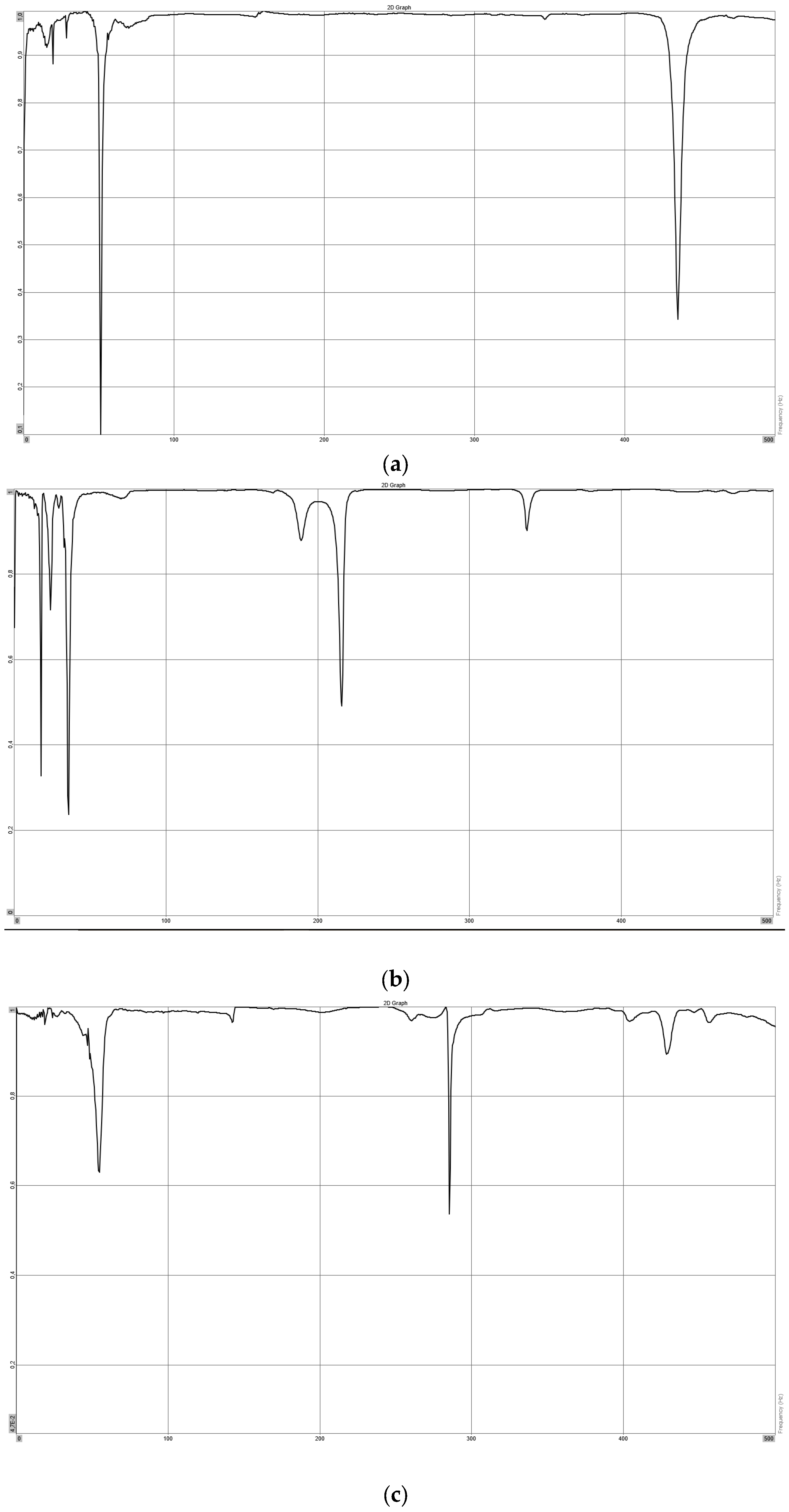
A representative coherence plot for measurement point 8 for the three laminate configurations is presented in
Figure 15.
The corresponding natural frequencies are summarized in
Table 6,
Table 7 and
Table 8, where numerical results are presented alongside experimentally identified values for each of the three specimens per configuration. Additionally, the average experimental frequencies are provided to facilitate a direct comparison with the finite element predictions.
The identified mode shapes were found to be consistent across all three specimens within each laminate configuration. Therefore, for clarity, only representative mode shapes are presented. Similarly to the bending test results, the finite element model exhibits a tendency to slightly overestimate the stiffness of the structure, which results in higher predicted natural frequencies compared to the experimental values. Despite this, the overall trends are consistently captured by the numerical model. The identified mode shapes were consistent across all specimens and configurations. The first and second modes correspond to bending-dominated behavior, while the third mode is associated with torsional deformation. A clear trend can be observed in the natural frequencies with increasing ply angle deviation. For the first and second modes, a gradual decrease in frequency is noted as the fiber orientation departs from the 0° direction. In contrast, the third (torsional) mode exhibits an increase in frequency with increasing ply angle. This behavior can be physically explained by the directional properties of the composite material. As the fiber orientation deviates from the primary load-carrying direction, the laminate becomes less efficient in resisting bending loads, leading to reduced bending stiffness and lower bending frequencies. At the same time, the change in fiber orientation enhances the laminate’s ability to resist torsional deformation, resulting in an increase in torsional stiffness and the corresponding natural frequency.
The coherence plots for measurement point 8, obtained for the different specimens, are shown below.
3.3. Flutter Velocity Calculation
A simplified quasi-steady aeroelastic model was adopted to estimate the critical flutter velocity of the investigated plate structures [
32,
33]. he formulation is based on a two-degree-of-freedom bending–torsion system, in which the interaction between the dominant bending and twisting vibration modes governs the onset of flutter. Within the quasi-steady framework, aerodynamic forces are assumed to depend only on the instantaneous structural deformation and angle of attack, while unsteady aerodynamic effects are neglected. For a simplified rectangular plate configuration, the flutter onset velocity can therefore be expressed in closed form as [
17,
32]:
In Equation (1)
is the chord length,
is the radius of gyration about the mid-chord,
is the dimensionless plate airstream mass ratio,
is the relative distance between the aerodynamic and shear center (expressed as a fraction of the chord length), and
is the lift gradient (for flat and rectangular plate the lift gradient is 2
/rad). The aerodynamic center is at 0.25 aft the leading edge, and the shear center us at half the chord, therefore in this case
is 0.25. Therefore Equation (1) can be rewritten as:
Analytically calculated flutter velocities are provided in
Table 9 for different laminate configurations, assuming the specimen can be represented as a clamped wing-like structure with a mass of 13 g (corresponding to the mass of the tested sample) and a chord length of 25 mm.
The influence of the structural modal separation on the flutter velocity can be directly inferred from the governing expression, in which the critical speed depends on the difference between the squared torsional and bending natural frequencies, i.e., . As this term increases, the resulting flutter velocity also increases, indicating that a larger separation between the bending and torsional modes enhances aeroelastic stability. Conversely, when the two natural frequencies approach each other, the system becomes more susceptible to flutter due to the reduced dynamic decoupling between bending and torsion. Since the natural frequencies constitute direct input parameters in the flutter velocity formulation, any discrepancies between experimentally measured and numerically predicted modal properties directly propagate into the calculated flutter speed. As a result, even relatively small errors in the estimation of bending and torsional frequencies may lead to noticeable variations in the predicted flutter velocity. This highlights the importance of accurate modal characterization, as the reliability of aeroelastic predictions is strongly dependent on the precision of the underlying dynamic properties used in the model. In the case of the L10 configuration, the differences between experimentally measured and numerically predicted natural frequencies were comparatively small for both bending and torsional modes. As a consequence, the resulting flutter velocity values were identical.
4. Conclusions
This study investigated the influence of small ply angle deviations on the structural response of CFRP laminates representative of UAV components using a combined experimental and numerical approach. The obtained results allow direct reference to the research questions formulated in the introduction. First, it was demonstrated that even relatively small deviations in fiber orientation can measurably affect key structural parameters. In the case of bending response, an increase in ply angle resulted in increased deflections under the same load, indicating a reduction in effective bending stiffness. This effect was clearly visible when comparing the L0, L5, and L10 configurations. Similarly, in the modal analysis, a consistent trend was observed: the first and second (bending-dominated) natural frequencies decreased with increasing fiber misalignment, while the third (torsional) mode showed an opposite tendency, increasing with ply angle. These results confirm that even modest deviations in fiber orientation may alter both static and dynamic characteristics of slender structures. From an aeroelastic perspective, such changes are particularly relevant, as reductions in bending stiffness and natural frequencies may lower flutter margins, while changes in torsional behavior can modify coupling effects and potentially shift instability boundaries.
Regarding the second research question, the adopted methodology proved to be sufficiently sensitive and consistent for engineering assessment. The combination of cantilever bending tests and experimental modal analysis enabled the detection of relatively small differences between laminate configurations. At the same time, these methods remain significantly more accessible than full-scale material characterization procedures, making them suitable for practical applications, especially in small-scale UAV development environments.
With respect to the third research question, the finite element model demonstrated good predictive capability. In both bending and modal analyses, the numerical results showed satisfactory agreement with the experimental data and successfully captured the observed trends related to ply angle variation. However, a consistent tendency of the model to slightly overestimate structural stiffness was observed, resulting in lower predicted deflections and higher natural frequencies compared to experimental results. This behavior is attributed to the idealized nature of the model, which does not account for manufacturing imperfections such as local fiber waviness, resin-rich areas, or minor geometric inconsistencies inherent to manual lay-up processes. Despite this limitation, the level of agreement can be considered sufficient for early-stage design and rapid prototyping purposes.
The proposed experimental methodology also shows potential for implementation in industrial quality assurance procedures for small-scale composite UAV structures. Since both cantilever bending tests and experimental modal analysis are relatively fast, non-destructive, and require limited equipment compared to full material characterization campaigns, they could serve as practical verification tools during prototype development and small-series production. For example, reference specimens manufactured with nominal ply orientations could be used to define acceptable deformation or modal response ranges. In the case of bending tests, a pass/fail criterion could be established by assuming that the measured deformation under a predefined load should not deviate by more than a specified threshold (e.g., 5%) from the reference response. Similarly, modal testing could be applied to monitor changes in structural stiffness through comparison of selected natural frequencies. In practical applications, higher-order modes may be particularly useful due to their increased sensitivity to local stiffness variations and ply misalignment. Such approaches could provide a relatively simple method for identifying manufacturing inconsistencies and improving process repeatability without the need for costly imaging or destructive inspection techniques.
Several limitations of the experimental methodology should be acknowledged. In the modal analysis, the use of a contact accelerometer introduced additional mass to relatively lightweight specimens, which may have influenced the measured natural frequencies. For improved accuracy, future studies should consider non-contact measurement techniques such as laser Doppler vibrometry (LDV). In addition, the use of an impact hammer, while suitable for rapid experimental identification, may limit repeatability and control of excitation conditions, particularly in higher frequency ranges. Therefore, alternative excitation strategies based on piezoelectric actuators or electrodynamic shakers could provide more consistent and repeatable input signals, which is especially relevant for more advanced modal characterization and structural health monitoring applications [
34,
35].
In the bending tests, displacement was measured manually, which limits precision and repeatability. The implementation of an integrated displacement measurement system (e.g., digital image correlation or LVDT sensors) would significantly improve data quality. Additionally, extending the experimental setup to include strain measurements could provide deeper insight into local structural behavior and improve validation of numerical models. Overall, the results indicate that properly constructed finite element models can effectively capture the influence of ply angle deviations on both bending and dynamic response of composite laminates. This supports increased reliance on simulation-based approaches in the assessment of structural variability, particularly in contexts where extensive experimental campaigns are impractical. Similar trends can also be observed in a broader range of composite engineering applications, including aerospace, space structures, and other lightweight composite systems, where numerical simulations are widely used to evaluate structural performance and guide design decisions. Similar trends can also be observed in a broader range of composite engineering applications, including aerospace, space structures, and other lightweight composite systems, where numerical simulations are widely used to evaluate structural performance and guide design decisions. In this study maximum difference between numerical and experimental test is 12.42% for bending test and 7.97% for modal test. Quami and Hashemi [
36] in their study reported the isolated rocket fin numerical result is within 5% of that obtained experimentally. The attached rocket fin was even closer, with a percent difference of less than 1% between the numerical and experimental results. Stosiak et al. [
5] proved that numerical simulations can provide strong consistency with experimental results for composite actuator components—the difference between the calculations and the experimental results for circumferential deformations is less than 5% and for axial deformations 15.5% and 10.4%. The accuracy obtained in this work falls within a comparable and widely accepted range.
In conclusion, the presented results highlight the necessity of a balanced design approach when considering ply angle deviations in CFRP structures intended for UAV applications. While increased fiber misalignment was shown to reduce bending stiffness and consequently increase static deflections under load, the same structural modifications may also lead to an increase in the predicted flutter velocity due to the increased separation between bending and torsional natural frequencies. This indicates that improvements in aeroelastic stability, in terms of higher flutter margins, may occur simultaneously with a deterioration in static stiffness performance. As a result, the design of composite wing-like structures should not treat static and dynamic responses independently, but rather as coupled phenomena requiring a trade-off between structural compliance and aeroelastic stability.
The present study also underlines that the finite element model tends to systematically overestimate structural stiffness due to the assumption of perfectly manufactured plies. To address this limitation in practical engineering applications, a calibration-based knock-down approach can be introduced, in which material properties (primarily and ) are adjusted using experimentally derived reduction factors obtained from representative specimens manufactured under realistic process conditions. By comparing numerical predictions with experimental bending and modal results across multiple laminate configurations, conservative reduction factors can be identified and subsequently applied in simulation workflows. Such an approach allows the incorporation of manufacturing-induced imperfections, including fiber waviness and resin-rich regions, into the numerical model in a simplified but effective manner, improving its relevance for industrial design and UAV structural assessment.