1. Introduction
Global research efforts aimed at preventing reinforcement corrosion in reinforced concrete building systems indicate that fiber-reinforced polymer (FRP) reinforcements are considered a potential solution [
1]. Chemical reactions triggered by environmental conditions cause the steel reinforcement embedded in concrete to corrode, which negatively affects the structural strength of the concrete. Such deterioration not only increases maintenance and repair costs but also significantly reduces the service life of structures [
2]. In this context, various engineering solutions have been developed to prevent corrosion-related damage. Among these solutions, the use of glass fiber-reinforced polymer (GFRP) materials, which exhibit high resistance to corrosion, stands out [
3]. Concrete is a widely preferred material in the construction industry due to its low cost, ease of application, and long-lasting structure [
4]. At the beginning of reinforced concrete systems, iron bars were used as reinforcement, but over time these materials were replaced by higher-strength steel reinforcements. However, the use of steel reinforcements in concrete has raised durability issues, particularly corrosion. In structures exposed to harsh environmental conditions and chemical effects, the concrete cover may not adequately protect the steel reinforcement, which can lead to corrosion of the reinforcement and damage to the structures before the expiration of their expected service life [
4].
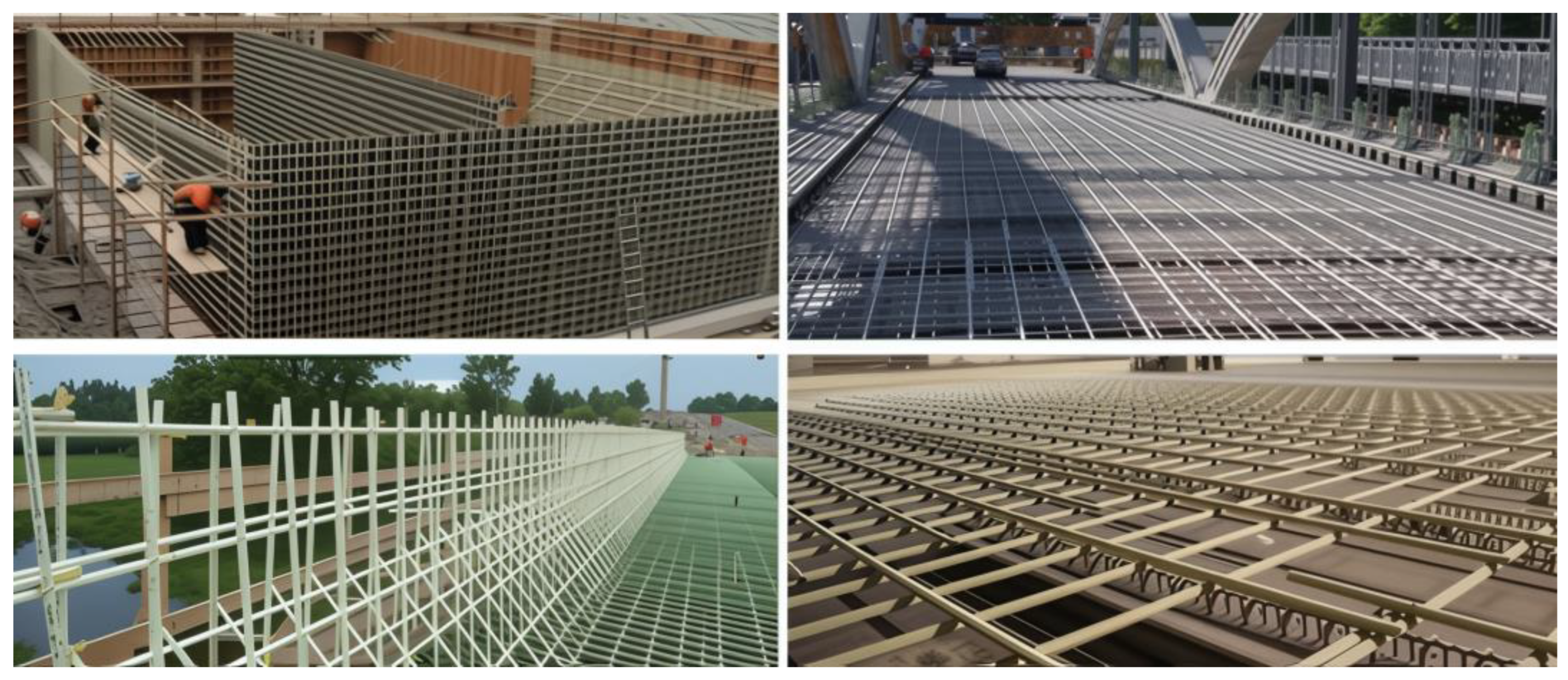
Figure 1 demonstrates that fiber-reinforced polymer (FRP) composite materials are increasingly being utilized in reinforced concrete structures due to their advantageous properties, such as lower specific weight, higher strength, and superior durability against freeze–thaw cycles compared to conventional reinforced concrete systems [
4]. From the past to the present, the use of steel reinforcement to resist tensile forces has been one of the basic applications of reinforced concrete structures. However, in recent years, FRP composites consisting of carbon, glass, basalt, or aramid fibers embedded in a resin matrix have emerged as alternative reinforcement elements with the potential to replace traditional steel reinforcement [
5].
There are numerous studies in the literature on the use of glass fiber-reinforced polymer (GFRP) reinforcement to prevent corrosion in reinforced concrete structural elements. In this context, the mechanical properties, adhesion behavior, bending, and shear performance of GFRP reinforcement, as well as the advantages it offers over traditional steel reinforcement, have been examined in detail in many studies. However, a significant portion of these studies address a limited number of parameters and primarily evaluate the effect of a single variable (e.g., reinforcement diameter, concrete class, or stirrup spacing). Comprehensive evaluations that consider multiple parameters simultaneously are limited in number. In this study, the structural behavior of GFRP-reinforced beams was analyzed using both experimental and numerical methods, evaluating different concrete strength classes (B25 and B40), GFRP reinforcement diameters (Ø10 and Ø12 mm), and stirrup spacings (50 mm and 100 mm) together. Thus, a comprehensive approach that was lacking in the literature has been presented. Below is a summary of some studies related to this topic found in the literature.
The flexural response of concrete beams reinforced with glass fiber-reinforced polymer (GFRP) bars was assessed using both laboratory experiments and numerical approaches [
6]. As part of the test program, nine beam specimens were subjected to four-point loading, considering different concrete grades (30, 40, and 50 MPa) and varying reinforcement percentages (0.75%, 1.02%, and 1.28%). Key parameters such as load–displacement behavior, crack propagation, and failure mechanisms were evaluated. To replicate the test conditions, finite element simulations were conducted using ANSYS R15.0, and the numerical outcomes were compared with experimental results. The results demonstrated that GFRP reinforcement contributes to increased flexural stiffness and improved crack resistance, and that the numerical model predictions aligned well with experimental data [
6]. Additionally, a comparative investigation was conducted on the flexural behavior of beams reinforced with GFRP as a potential substitute for conventional steel bars [
7]. In this extended test program, six full-scale specimens were examined to determine their structural stiffness, load-bearing capacity, displacement characteristics, and failure behavior. It was observed that beams incorporating GFRP exhibited significantly enhanced load-bearing performance relative to steel-reinforced counterparts. However, greater deflections and more extensive cracking occurred due to the inherently low modulus of elasticity of GFRP. These results emphasize the importance of evaluating not only the mechanical benefits of GFRP but also its potential shortcomings [
7]. The flexural performance of continuous reinforced concrete beams reinforced with glass fiber-reinforced polymer (GFRP) rods was experimentally evaluated under different concrete compressive strength classes (30, 50, and 70 MPa) [
8]. Within the scope of the study, ten beam specimens with varying concrete strengths and reinforcement ratios were tested using a four-point bending test. The results obtained were analyzed in terms of parameters such as load-carrying capacity, vertical displacement, crack width, stress distribution, and damage mechanisms. The findings revealed that the increase in reinforcement ratio led to improvements in bending capacity, while also causing significant reductions in crack width and displacement. These results indicate that GFRP reinforcement can be considered an effective and reliable alternative for enhancing the structural performance of continuous reinforced concrete beams [
8].
In a separate investigation, the bending behavior of reinforced concrete beams was evaluated analytically when glass fiber-reinforced polymer (GFRP) bars were incorporated either as a substitute for or alongside traditional steel reinforcement [
9]. Twenty-four beam models were assessed through nonlinear finite element simulations using ANSYS R15.0 software, considering different reinforcement percentages and a range of concrete strengths (B30, B35, B40, B45). Although GFRP was found to offer superior corrosion resistance, it demonstrated limited ductility. Beams with partial GFRP reinforcement showed improved flexural stiffness and reduced deflection at mid-span. These outcomes suggest that GFRP bars can serve as a viable supplement to conventional steel reinforcement [
9]. Similarly, another study examined the bending behavior of reinforced concrete beams reinforced with glass fiber-reinforced polymer (GFRP) reinforcement in comparison with traditional steel-reinforced beams. The GFRP reinforcements were dimensioned according to ACI 440.1R-15, while the steel reinforcements were dimensioned according to NBR 6118-2014 standards, and both groups were designed to carry the same bending moment [
10,
11,
12]. As part of the experimental study, two groups consisting of three samples each were formed and four-point bending tests were performed. GFRP-reinforced beams carried an approximately 64% higher ultimate bending moment compared to steel-reinforced beams; however, they exhibited greater displacement and more cracking. GFRP beams exhibited elastic behavior, returning to their initial form when the load was removed, while plastic deformations were observed in steel-reinforced beams. When evaluated in terms of serviceability limit state, two GFRP-reinforced beams exceeded the target limit displacement. In conclusion, although GFRP reinforcements cause greater deformation due to their low elastic modulus, they can ensure structural safety thanks to their high load-carrying capacity. This material, which can be used as an alternative to steel under aggressive environmental conditions, should be carefully dimensioned considering service limit states.
One of the recent approaches developed to improve the shear behavior of RC elements reinforced with GFRP bars is the use of ECC material, which offers high ductility and excellent crack control capacity [
13]. In this study, the shear behavior of RC beams produced with ECC and reinforced with GFRP bars was experimentally investigated. Eight beam specimens with different shear span-to-depth ratios and varying stirrup ratios were tested under four-point bending. The results show that the load-bearing capacity of ECC beams reinforced with GFRP is higher than that of beams produced with traditional concrete. Despite the low elastic modulus of GFRP, its combination with ECC significantly improved the deformation capacity of the system. Furthermore, an increase in stirrup ratio led to a notable enhancement in shear strength. These findings demonstrate that the combined use of GFRP reinforcement and ECC material provides an effective structural system in terms of both strength and ductility. The use of GFRP reinforcements in reinforced concrete structural elements has gained increasing attention in recent years, particularly through studies investigating their effects on torsional strength [
14]. In this context, the present study experimentally investigates the structural performance of hollow-section reinforced concrete beams under torsion when reinforced with GFRP bars and GFRP stirrups. Torsion tests conducted on ten samples with different reinforcement configurations revealed that beams reinforced with GFRP have a higher torsion load-bearing capacity compared to control samples. In addition, it was observed that torsion cracks started later and spread over a narrower area in these samples. Moreover, torsional cracks in these specimens were observed to initiate later and propagate more narrowly. The positive effects of GFRP stirrups on stiffness and ductility were also notable, with load–displacement curves indicating a significant increase in energy dissipation capacity. These findings demonstrate that GFRP reinforcements can serve as an effective reinforcement solution not only in flexural and shear resistance, but also under torsional loading conditions.
Compared to traditional steel reinforcements, glass fiber-reinforced polymer (GFRP) bars offer several advantages such as corrosion resistance, high tensile strength, and light weight, which have led to their increasing use in reinforced concrete beams [
15,
16]. However, the lower elastic modulus of GFRP compared to steel can result in greater deflections and wider crack formation under flexural and shear loads, which in turn introduces certain structural limitations [
17,
18]. Furthermore, recent studies have shown that when GFRP reinforcements are used in combination with high-ductility cementitious composites (such as ECC), significant improvements can be achieved in shear capacity and ductility performance [
19]. In addition to these material-based innovations, nonlinear numerical analyses conducted using advanced finite element software such as ABAQUS (2022) have emerged as an effective method for predicting the structural behavior of GFRP-reinforced beams under complex loading conditions [
20]. Nevertheless, the current literature lacks comprehensive analyses that simultaneously consider multiple parameters such as reinforcement ratio, stirrup configuration, and matrix type. Therefore, this study aims to address this gap by evaluating the flexural behavior of GFRP-reinforced concrete beams through advanced parametric and model-based numerical analyses. GFRP reinforcements offer significant advantages such as high tensile strength and corrosion resistance, but due to their low modulus of elasticity, they exhibit lower stiffness compared to conventional steel reinforcement. This can result in larger displacements and wider crack openings in structural elements. Therefore, when evaluating the performance of reinforced concrete elements with GFRP, it is crucial to consider not only the load-carrying capacity but also parameters such as crack control, deformation amount, and ductility. In this context, this study examines the concrete compressive strength (25 MPa and 40 MPa), reinforcement diameter (Ø10 and Ø12 mm), and stirrup spacing (50 mm and 100 mm), systematically addressing these variables to comprehensively analyze the bending behavior of GFRP-reinforced beams. This study fills an important gap in the literature by revealing the effects of methods such as increasing concrete strength and reinforcing spacing on crack widening and displacement increase caused by GFRP. In conclusion, this study demonstrates that GFRP-reinforced beams not only offer high load-carrying capacity but also enable optimized crack control through appropriate concrete strength and reinforcement detailing, thereby providing important contributions to structural design processes. Although various experimental and numerical studies on the behavior of GFRP-reinforced concrete beams exist in the literature, a significant portion of these investigations are limited to specific parameters. This study simultaneously addresses critical parameters such as concrete strength, reinforcement bar diameter, and stirrup spacing that affect the load-carrying capacity and displacement performance of GFRP-reinforced beams, thereby offering a comprehensive structural assessment that is often lacking in previous research. By utilizing ABAQUS (2022) software as the numerical modeling tool, the complex behavior of GFRP-reinforced elements under various loading conditions has been simulated in detail, yielding findings that provide valuable guidance for decision-makers in structural engineering practice.
2. Materials and Methods
To investigate the structural behavior of reinforced concrete beams numerically, the finite element method was adopted. The analyses were carried out using ABAQUS (2022) software, which offers advanced numerical modeling capabilities. In the three-dimensional nonlinear finite element analyses, the Concrete Damage Plasticity (CDP) model was employed to accurately represent the complex stress–strain behavior of concrete. Thanks to ABAQUS’s extensive library of element and material models, the fracture behavior, crack formation, and load-carrying capacity of the elements were realistically simulated. In this way, the performance of FRP-reinforced beams, used as an alternative to conventional steel reinforcement, was comprehensively evaluated.
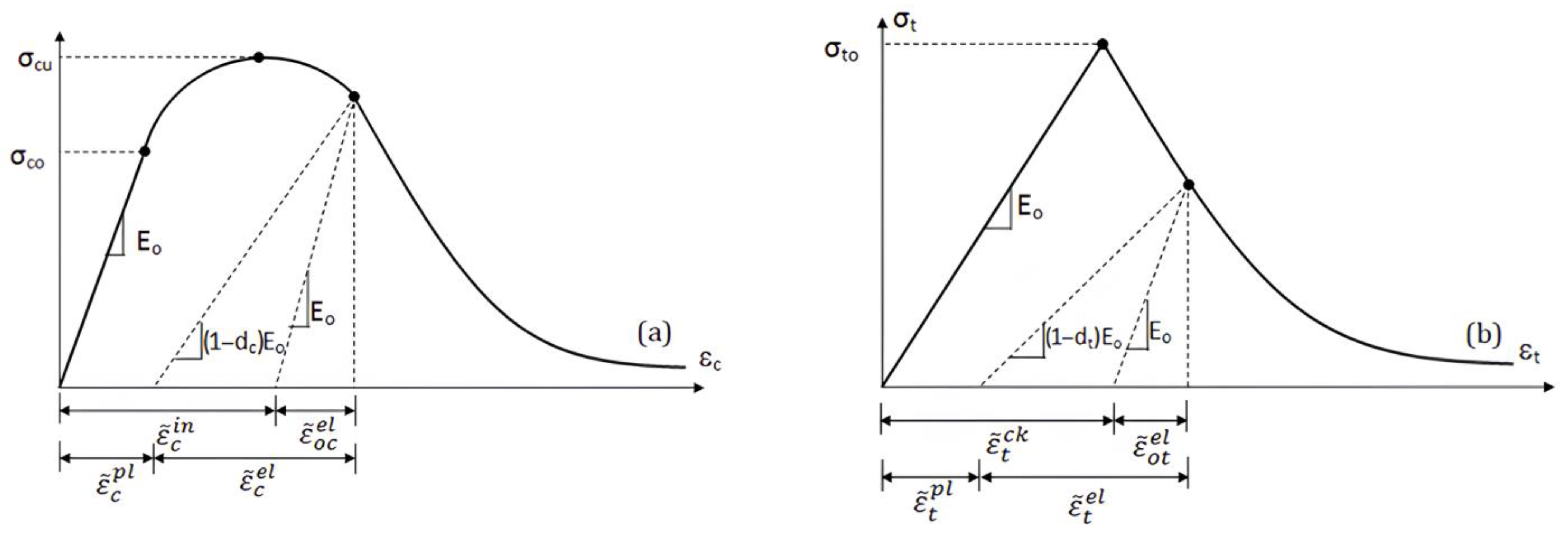
The concrete damage plasticity method has been widely adopted in many academic studies due to its ability to realistically represent the nonlinear and multiaxial behavior of concrete. The Concrete Damage Plasticity (CDP) model is one of the constitutive models that can be used to predict the structural behavior of concrete. This model explains concrete behavior by defining scalar damage variables. As shown in
Figure 2, the response of concrete under tension and compression can be characterized using the CDP model. In numerical analyses, the Concrete Damage Plasticity (CDP) model, which was developed to simulate the behavior of concrete, was adopted [
21]. The model is based on two types of damage: cracking (tension) and crushing (compression). Within the CDP model, in addition to the elastic modulus and Poisson’s ratio, five damage-related parameters must be defined. The values of these parameters are provided in
Table 1. In the analyses, the density of concrete was taken as 2400 kg/m
3 and the Poisson’s ratio was assumed to be 0.2.
The parameters of the Concrete Damage Plasticity (CDP) model used in ABAQUS (2022) software are presented in
Table 1. In order to define the yield or failure surface of concrete, five key parameters must be specified [
23,
24]. The first parameter, Ψ (dilation angle), represents the angle of plastic dilation and is set to 31°. The second parameter, ϵ (flow potential eccentricity), defines the eccentricity of the flow potential and is assigned a value of 0.1. The third parameter,
, represents the ratio of the initial biaxial compressive yield stress to the initial uniaxial compressive yield stress, and this ratio is set to 1.16.
The fourth parameter, K, is the ratio of the second stress invariant on the tensile meridian to that on the compressive meridian, and its value is selected as 0.667. Lastly, ν (viscosity parameter) represents the viscosity effect of the model and is defined with a value of 0.0001 in this study. The CDP model used to simulate the material behavior of concrete represents two primary damage mechanisms—cracking and crushing—through scalar damage variables. This model provides a comprehensive approach in numerical analyses by defining the behavior of concrete under both tensile and compressive stresses. The stress–strain response behavior associated with the CDP model is illustrated in
Figure 2.
After reaching the peak tensile and compressive stresses on the stress–strain curves, plastic deformations occur, and the elastic modulus of the concrete begins to decrease. This reduction in the elastic modulus is expressed based on the damage parameters dt and dc, which range between zero and one. A value of zero indicates no damage, while a value of one represents maximum damage.
The stresses developed under uniaxial tensile and compressive loading are expressed by the following equations (Equations (1) and (2)).
The plastic strains developed under uniaxial tensile and compressive loading are expressed by the following equations (Equations (3) and (4)).
Tension stiffening, which describes the change in elastic stiffness under tensile stresses, is one of the fundamental mechanisms that must be considered when modeling the interaction between reinforcement and concrete. This effect is particularly important in representing cracks that develop as a result of loss of bond between concrete and reinforcement and lever moments. Tension stiffness can be defined based on the stress–strain relationship of concrete and the fracture energy required to resist crack formation. In order to realistically model the behavior of the interface between the reinforcement and the concrete, this effect, which enables the reinforcement to continue contributing to load transfer along the cracks, must be integrated into the concrete material model. This approach also allows for the accurate reflection of the strain-softening tendency of cracked concrete. In this regard, the definition of the tensile stiffness parameter within the Concrete Damaged Plasticity (CDP) model is critical for the reliable simulation of the damage behavior of reinforced concrete structural elements. ABAQUS (2022) finite element software supports the definition of this parameter both through post-cracking stress–strain curves and through crack formation criteria based on fracture energy. Both methods contribute to a more realistic modeling of the tensile behavior of cracked concrete [
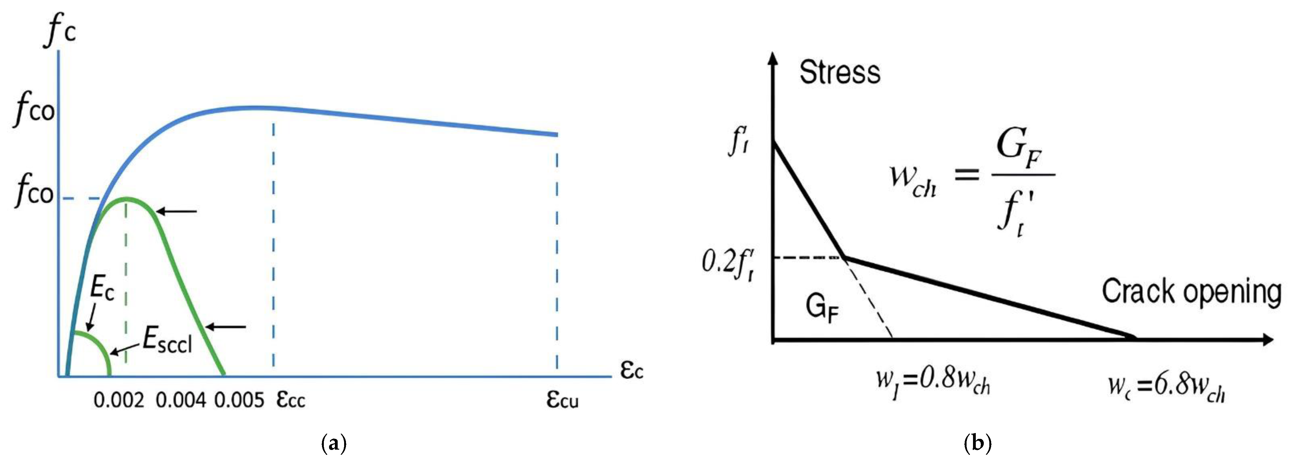
24]. Since the compressive and tensile stress behaviors of the experimental test specimens were not reported, these relationships were established using mathematical models available in the literature. For modeling the tensile behavior of concrete, a bilinear model, as shown in
Figure 3b, was adopted [
22]. The compressive behavior of concrete was obtained using the Mander concrete model, as shown in
Figure 3a [
25].
The crack opening width (
wc) is calculated as a proportion of the total external energy (
GF) applied per unit area required to initiate, propagate, and fully open a Mode I type crack in concrete. However, the Mode I tensile fracture energy of concrete is defined as a function of the compressive strength of concrete (
fc), and this relationship is presented in Equation (5) [
26]. In the given equation,
is a coefficient that depends on the maximum aggregate size (
dmax) of the concrete. Various values of this coefficient are provided in
Table 2.
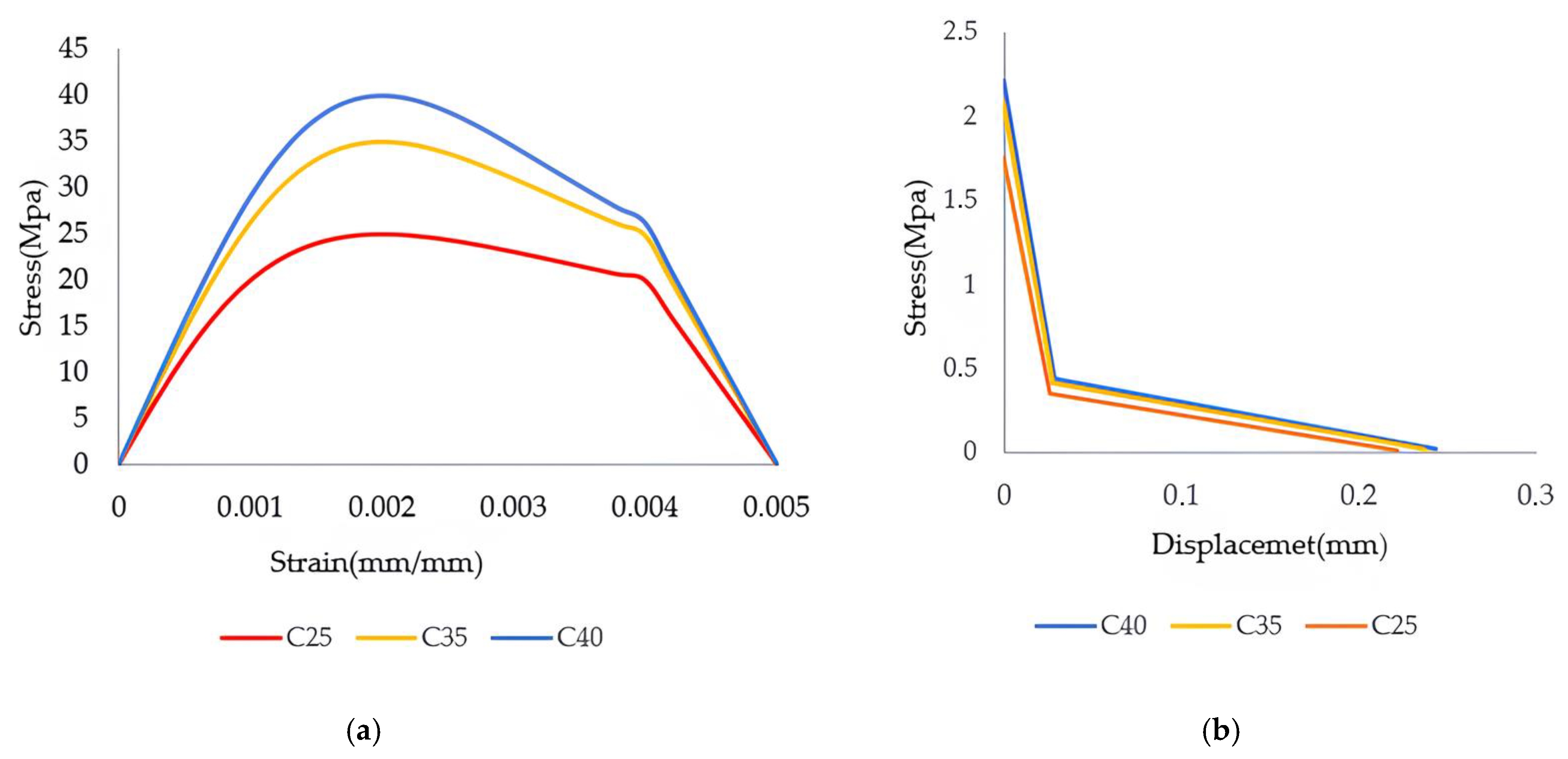
During the modeling process, the uniaxial tensile and compressive stress–strain curves were defined based on the theoretical approaches outlined above (
Figure 4). The fracture energy values (
Gf0) defined for different maximum aggregate diameters were used to model the tensile behavior, and these values are listed in
Table 2 [
27].
The concrete grade used for verification was C35, and the corresponding stress–strain and stress–displacement curves are presented in the figure. In the parametric study, concrete grades C25 and C40 were evaluated to compare the effects of different strength levels on the mechanical response of concrete (
Figure 4).
3. Verification of Experimental Data Using Finite Element Analysis
In order to assess the reliability of the proposed numerical model, reference was made to experimental results reported in previous studies [
28]. Within this scope, a reinforced concrete beam incorporating GFRP was examined as a potential substitute for conventional steel reinforcement. The geometric details of the tested specimen are illustrated in
Figure 5.
Data on the reinforcement details and material properties of the beam used for experimental verification are presented in detail in
Table 3 [
28]. The beam, labeled G3, belongs to the second test series and was reinforced with glass fiber-reinforced polymer (GFRP). In the compression zone, two Ø10 mm GFRP bars were placed, while in the tension zone, two Ø16 mm GFRP bars were used. To enhance shear resistance, Ø10 mm stirrups were provided at 37.5 mm spacing. Additionally, the beam was cast using concrete with a compressive strength of 35 MPa. This reinforcement configuration and material properties served as the reference for the development of the finite element model.
Table 4 presents the mechanical properties of the GFRP bars used in the experimental study [
28]. Two different bar diameters were utilized: 10 mm and 16 mm. The 10 mm bar has a cross-sectional area of 78.54 mm
2, an ultimate tensile strength of 861.88 MPa, an ultimate tensile strain of 1.63%, and a modulus of elasticity of 46 GPa. The 16 mm GFRP bar, labeled as G3 in the study, has a larger cross-sectional area of 201.06 mm
2, a higher tensile strength of 958.41 MPa, an ultimate strain of 1.77%, and an elastic modulus of 53.05 GPa. These mechanical properties were used as input parameters for the finite element model to realistically simulate the behavior of GFRP-reinforced concrete beams.
Basic data on the mechanical properties of GFRP reinforcements used in the experimental study are presented in detail in
Table 4 for use in numerical analyses [
28]. This specimen, identified by the label “G3”, was evaluated only among the samples belonging to the second series. GFRP bars were chosen as an alternative reinforcement material to traditional steel reinforcement in this study. Two GFRP reinforcements with a diameter of 10 mm were placed in the compression zone of the beam, while two GFRP bars with a diameter of 16 mm were added to the tension zone to increase the bending load-carrying capacity. Steel stirrups were used in addition to the reinforcement configuration to improve shear strength and limit crack development. This reinforcement configuration is consistent with the practices commonly adopted in experimental studies. The aforementioned reinforcement layout forms the basis of the bending performance analyses conducted in this study.
5. Beam Geometry and Mesh Configuration
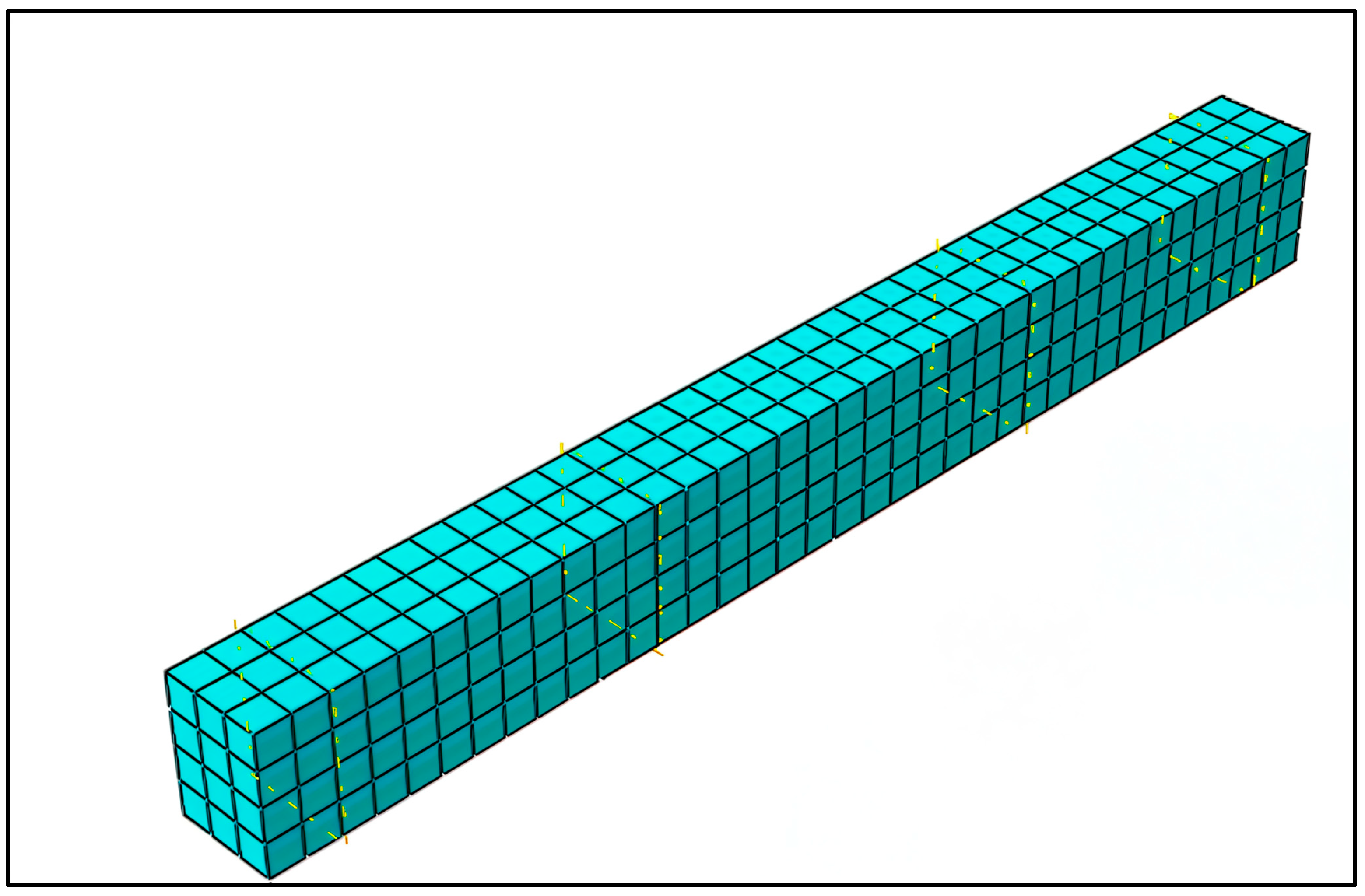
During the modeling process, steel and FRP reinforcements were defined as embedded within the concrete body and represented by three-dimensional truss elements (T3D2) with two nodes each. The concrete domain was modeled using eight-node linear brick elements with reduced integration (C3D8R), which are commonly preferred due to their accuracy and computational efficiency. In order to evaluate the effect of mesh resolution on the accuracy of the finite element analysis, a mesh sensitivity study was conducted. Within this scope, different mesh sizes were comparatively assessed in terms of both computational time and the stability of the results. As shown in
Figure 6, based on the evaluation, a mesh size of 50 mm was determined to be optimal, offering a suitable balance between numerical accuracy and computational performance, and was therefore adopted in the analyses.
The verification of finite element (FE) models developed using ABAQUS (2022) Standard software was performed by comparing them with experimental data obtained from reinforced concrete beam specimens. In this context, the agreement between model outputs and experimental results was evaluated based on fundamental structural response parameters such as load–displacement curves.
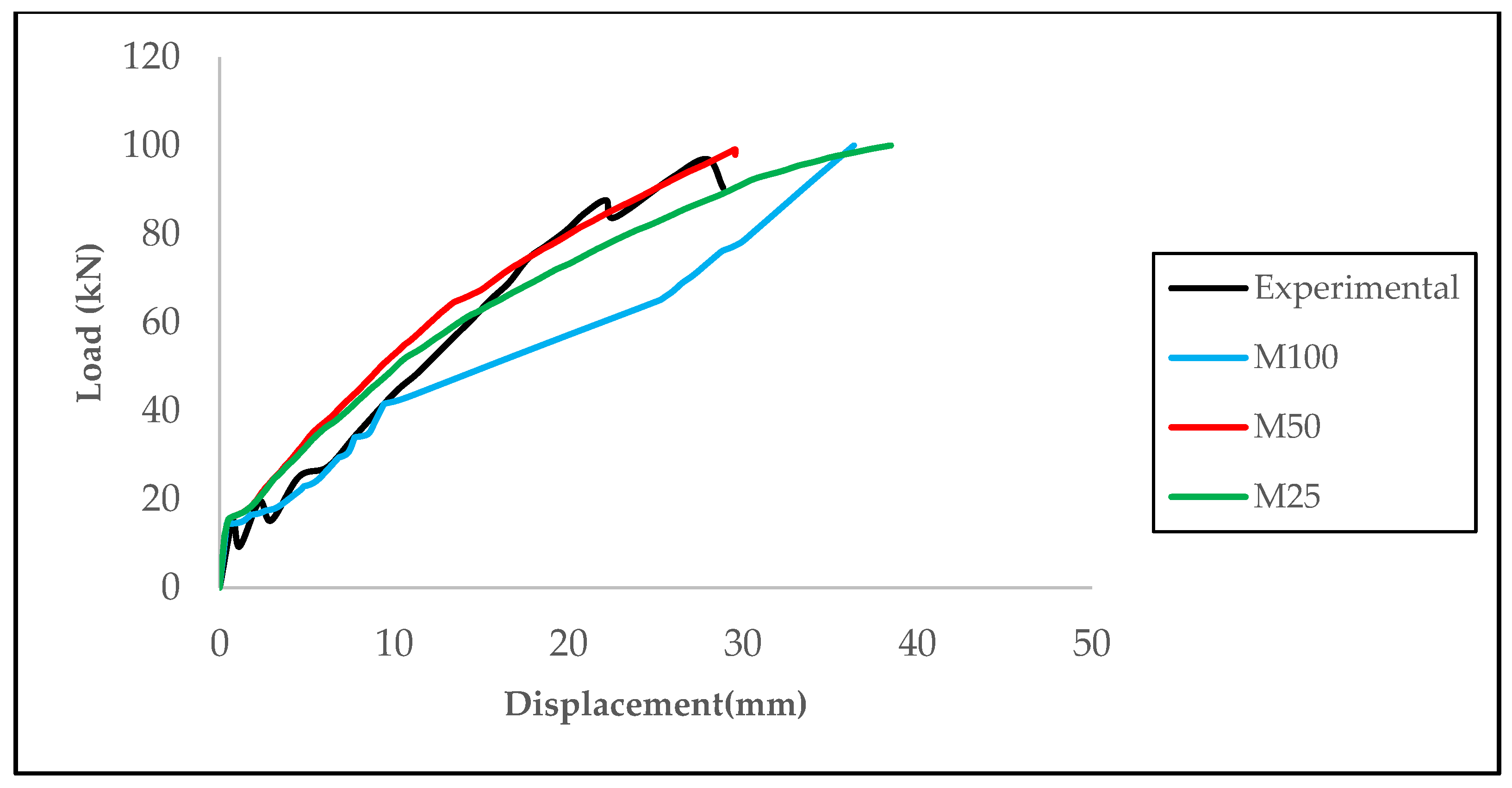
Figure 7 presents a comparison of numerical and experimental results for the reinforced concrete beam. During the comparison process, percentage differences were calculated using the experimental data as a reference. The findings indicate that the model successfully reflects the general loading behavior. Especially at the maximum load point, the experimental and numerical results completely overlapped; in other loading stages, the results were quite close to each other. In terms of maximum displacement, the numerical model yielded a value of 29.55 mm, while the experimental study yielded a value of 28.86 mm. This corresponds to a difference of approximately 2.4%, indicating that the model accurately represents the deformation behavior.
In addition, finite element models named M25, M50, and M100, which were created to examine the effect of different mesh densities on model accuracy, were compared. When examining the load–displacement curves presented in
Figure 7, it can be seen that the model with the M50 mesh provides the highest agreement with the experimental data. The M50 model produced the closest result to the experimental curve in terms of both load capacity and deformation level, particularly at the maximum load point, where it nearly matched the experimental data. In contrast, while the M25 model provided similar results in terms of displacement, its maximum load capacity remained slightly above the experimental data. The M100 model, on the other hand, deviates significantly from the experimental behavior in terms of both load and displacement due to its coarser mesh structure. In this regard, as illustrated in
Figure 8, the M50 mesh density emerges as the solution that provides the most appropriate balance between computational efficiency and numerical accuracy.
6. Parametric Study
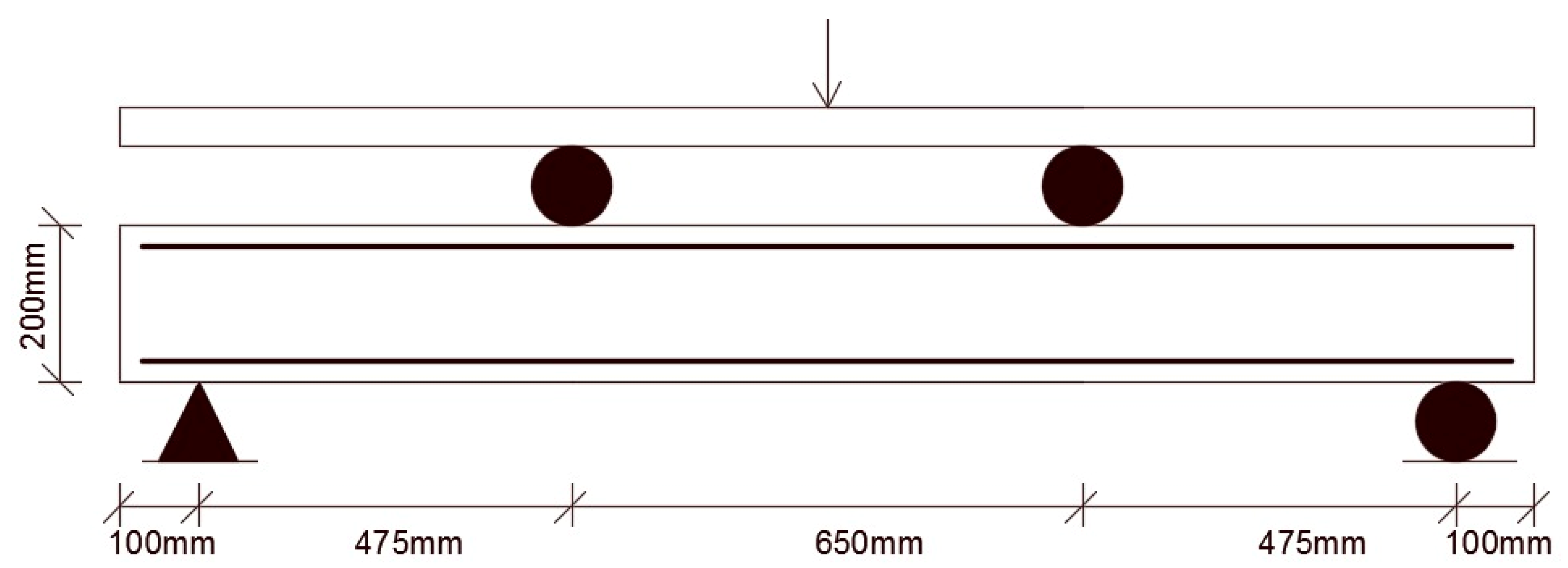
In this study, a series of beam models with varying parameters were investigated to evaluate the structural behavior of GFRP reinforcement bars under static loading. The primary variables examined include stirrup spacing, the compressive strength of concrete, and the configuration of tensile reinforcement. The beams used in the experimental program had dimensions of 2000 mm in total length, 1800 mm clear span, 150 mm width, and 200 mm depth (
Figure 9). A total of eight different beam models were prepared, with each group consisting of two beams. In each group, only one variable was altered while the others were kept constant. In the first group, the parameter under investigation was the stirrup spacing, which was varied between 50 mm and 100 mm. In the second group, the compressive strength of concrete was evaluated at two levels: 25 MPa and 40 MPa. In the third group, the modification of the reinforcement arrangement allowed for the observation and analysis of changes in the structural behavior of the beams.
The reinforced concrete beams used in the parametric study were designed with dimensions of 150 × 200 × 1800 mm. The total span of each beam was set to 1600 mm, and the shear span was determined as 475 mm. The beams were tested under a four-point bending configuration, with a clear distance of 650 mm between the two loading points. To enhance shear capacity and prevent shear failure, steel stirrups were provided in the shear regions. The longitudinal and transverse reinforcement details of the beams are presented in the related table (
Table 5).
In this study, beam specimens were systematically labeled to represent the concrete strength, longitudinal reinforcement type and diameter, as well as the stirrup spacing. For example, the label “B25_G10S50” refers to a specimen constructed with concrete having a characteristic compressive strength of 25 MPa (B25), 10 mm diameter glass fiber-reinforced polymer (GFRP) bars as longitudinal reinforcement (G10), and stirrups spaced at 50 mm intervals (S50). Similarly, “B40_G12S10” denotes a beam specimen with 40 MPa concrete, 12 mm diameter GFRP bars, and 10 mm stirrup spacing. This labeling system provides a clear representation of the varying parameters among the specimens, facilitating the comparison and interpretation of the experimental results.
Data on the mechanical properties of steel and GFRP reinforcement bars to be used in parametric analysis are presented in detail in
Table 6 to serve as a basis for comparative evaluations [
29]. For the steel bar with a diameter of 10 mm, the yield strength is specified as 420 MPa, the ultimate tensile strength as 590.04 MPa, the ultimate strain as 32%, and the modulus of elasticity as 212 GPa. For the GFRP bars, the 10 mm diameter bar has an ultimate tensile strength of 1301.93 MPa, an ultimate strain of 3.05%, and a modulus of elasticity of 59 GPa, while the 12 mm diameter GFRP bar has an ultimate tensile strength of 1381.88 MPa, an ultimate strain of 3.90%, and the same elastic modulus of 59 GPa. These values were used as fundamental parameters in the numerical analyses conducted to evaluate the mechanical performance of reinforced concrete structural members with different reinforcement types.
8. Load–Deformation Response
GFRP bars, which possess high tensile strength along with a low modulus of elasticity, exhibit a brittle structural behavior that may lead to sudden failure due to these characteristics.
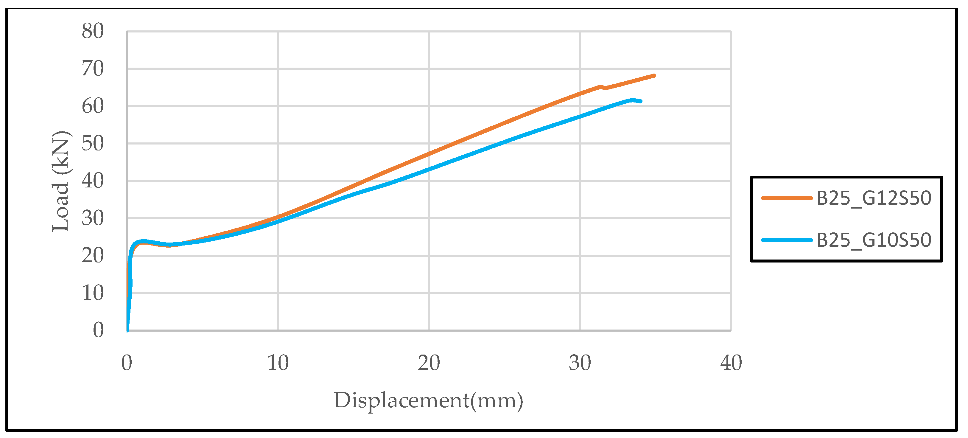
The load–displacement curves of beams with C25 concrete strength, reinforced in the tension zone with two GFRP bars of 10 mm and 12 mm diameter, are presented comparatively (
Figure 10). In both specimens, the stirrup spacing was kept constant and the elastic modulus of the reinforcement was assumed to be equal. The similar slopes observed in the elastic region reflect this assumption, while the specimen with 12 mm bars exhibited approximately 15% higher load capacity and greater displacement. These results indicate that increasing the bar diameter positively affects both ductility and load-carrying capacity.
The load–displacement responses illustrated in
Figure 10 and
Figure 11 were derived from finite element simulations conducted on beam models incorporating varying levels of concrete compressive strength and different GFRP bar diameters. These curves provide an opportunity to compare the effects of increasing GFRP reinforcement diameter and using high-strength concrete on the structural responses of beams. When comparing the graphs for the B25_G10S50 and B25_G12S50 specimens in
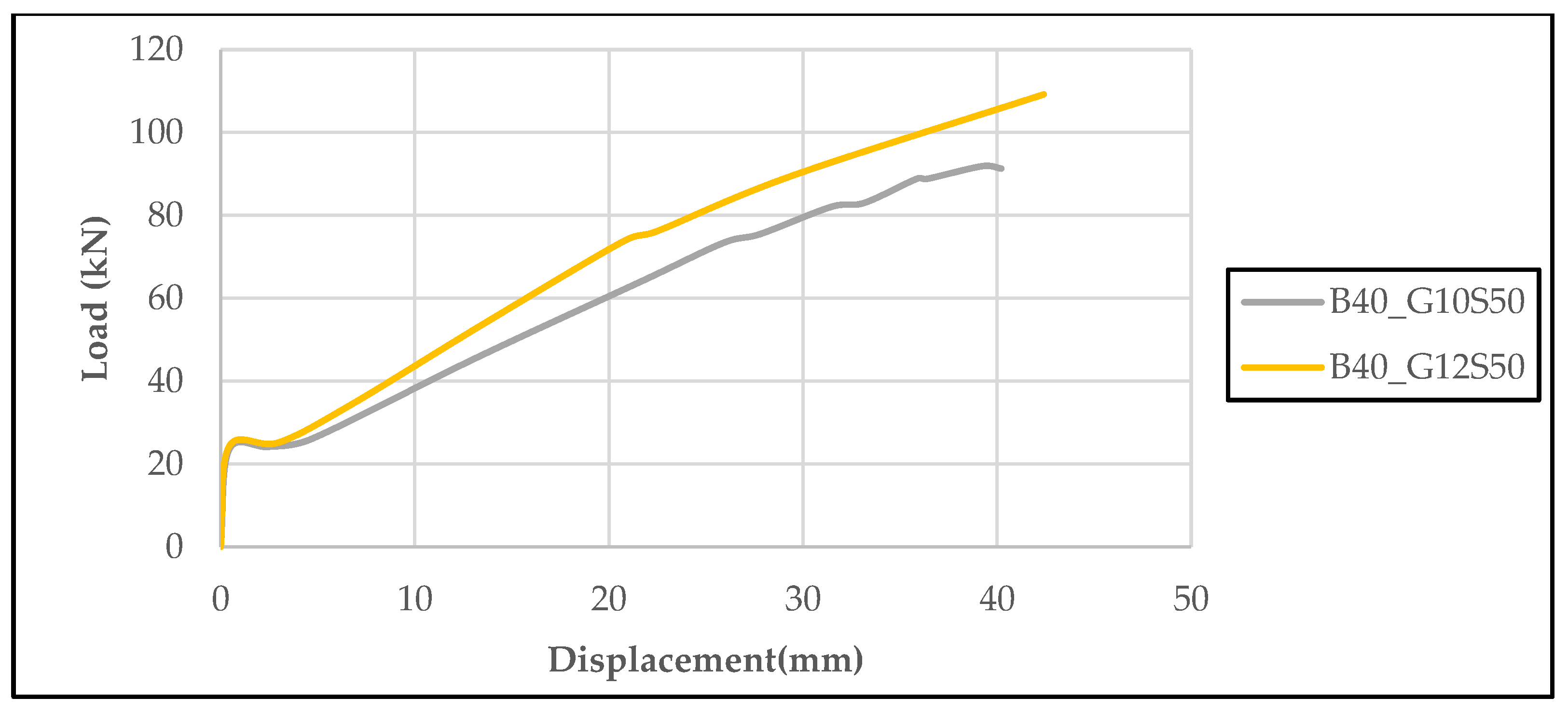
Figure 10, it is observed that the beam reinforced with 12 mm diameter GFRP reinforcement exhibits higher load-carrying capacity and increased displacement values compared to the specimen with 10 mm diameter reinforcement. A comparison of the B40_G10S50 and B40_G12S50 specimens presented in
Figure 11 reveals that increasing the diameter of the GFRP reinforcement leads to a marked enhancement in both the strength and deformation characteristics of the beam. This observation suggests that enlarging the reinforcement cross-sectional area, particularly when integrated with high-strength concrete, contributes significantly to improving the beam’s overall structural efficiency and ductility behavior.
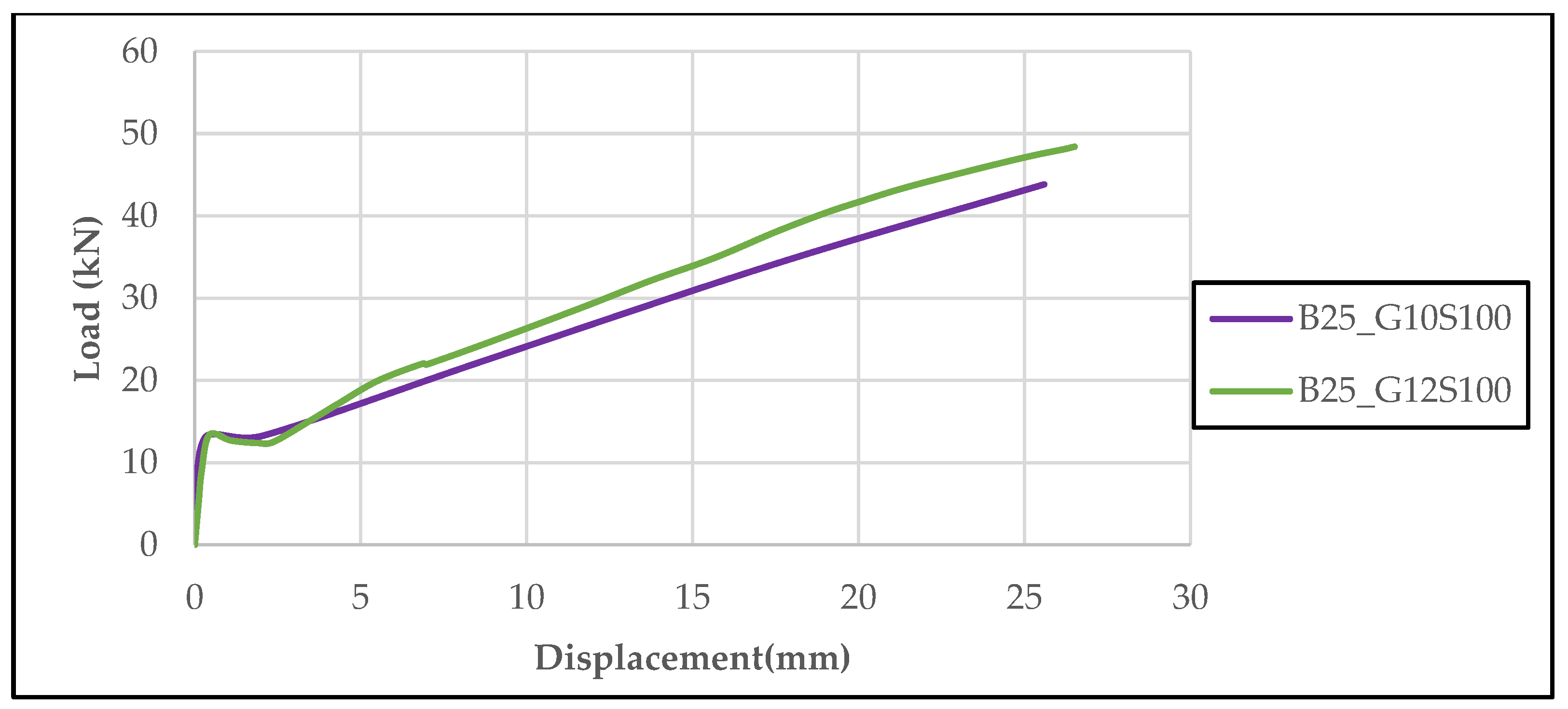
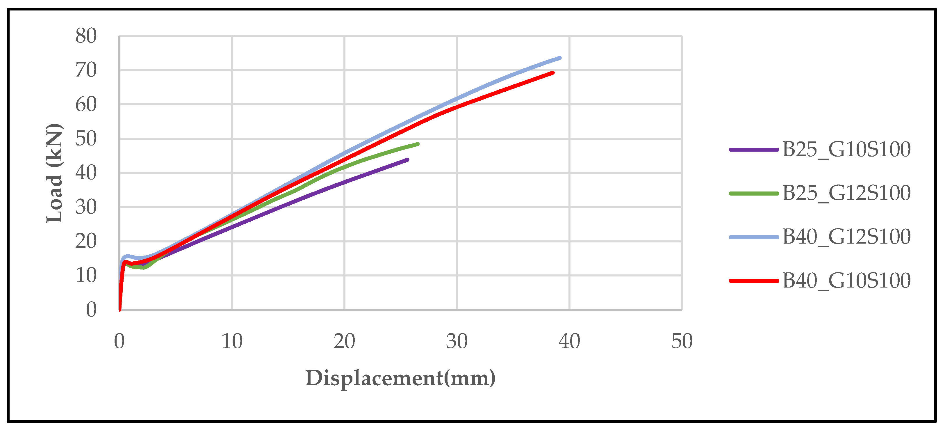
Figure 12 compares the load–displacement curves of beams with a concrete compressive strength of 25 MPa, reinforced in the tension zone with 10 mm and 12 mm diameter GFRP bars. Both specimens had a stirrup spacing of 100 mm, and this wide spacing was observed to have adverse effects on both load-carrying capacity and ductility. The beam with 12 mm reinforcement reached approximately 14% higher load capacity and exhibited greater displacement. The results clearly highlight that while increasing the reinforcement diameter has a positive effect, the wide stirrup spacing significantly limits the overall structural performance.
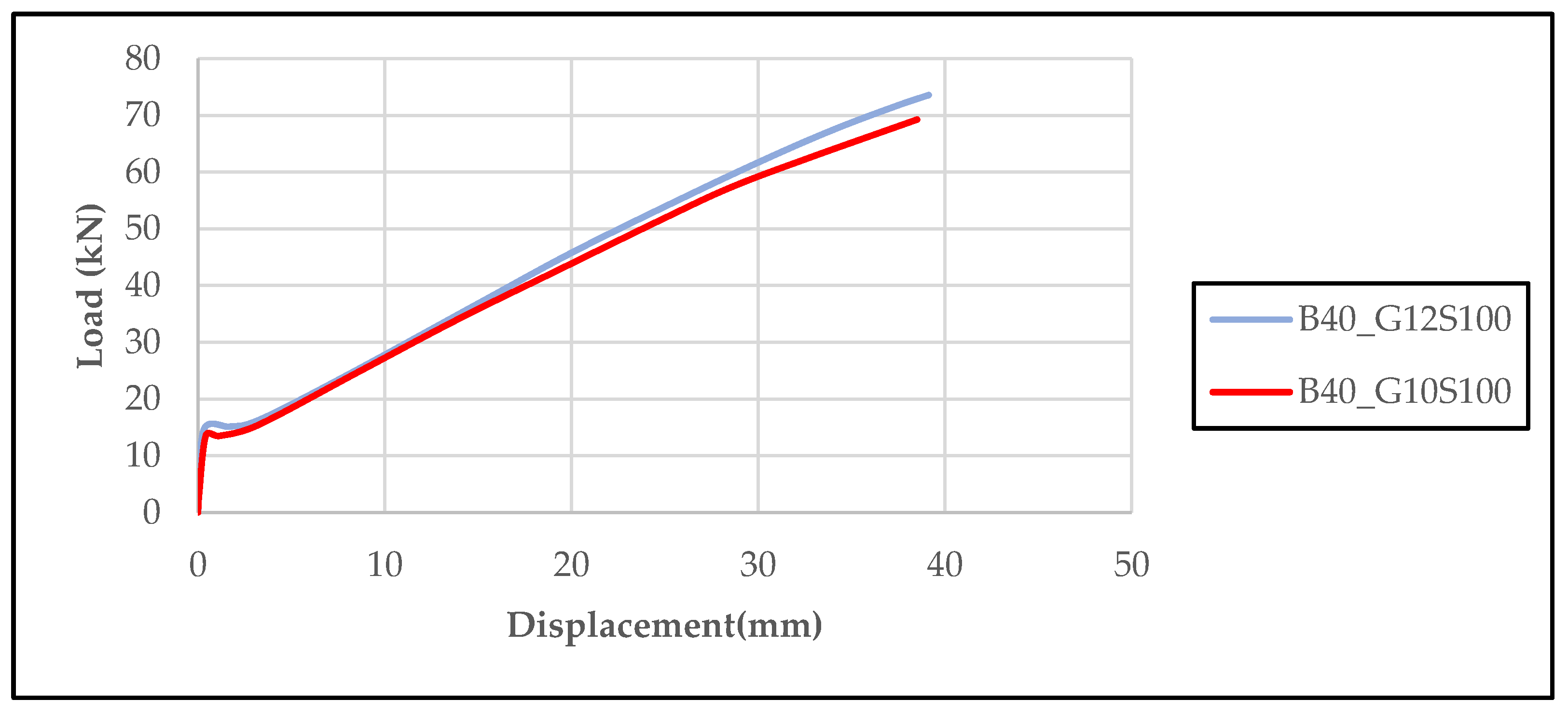
In
Figure 13, the load–displacement curves of beams produced with 40 MPa concrete and 100 mm stirrup spacing are presented comparatively. Despite the increase in reinforcement diameter (from 10 mm to 12 mm), no significant improvement in load-carrying capacity was observed. This indicates that, despite the high concrete strength, the wide stirrup spacing limited the effectiveness of the reinforcement and negatively affected the structural performance.
The graph presented in
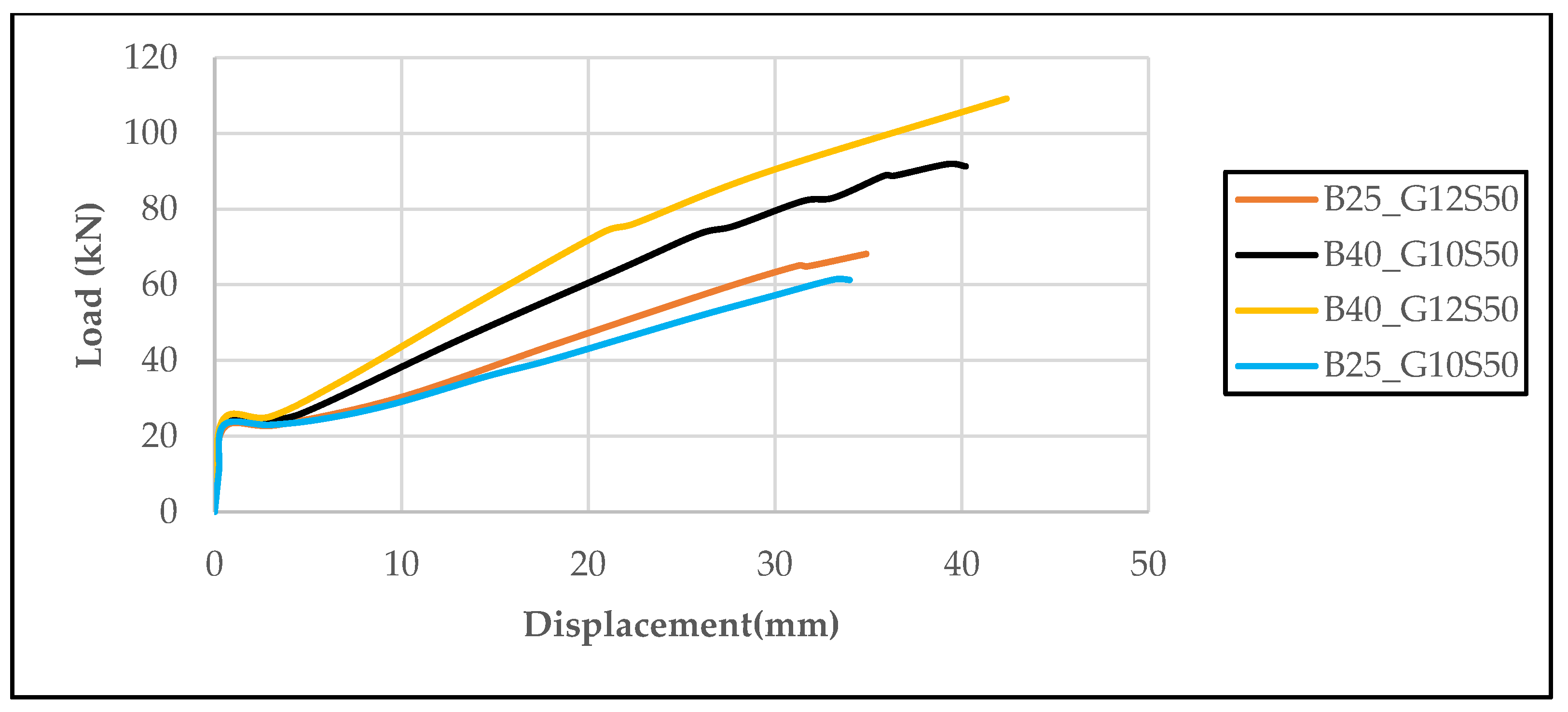
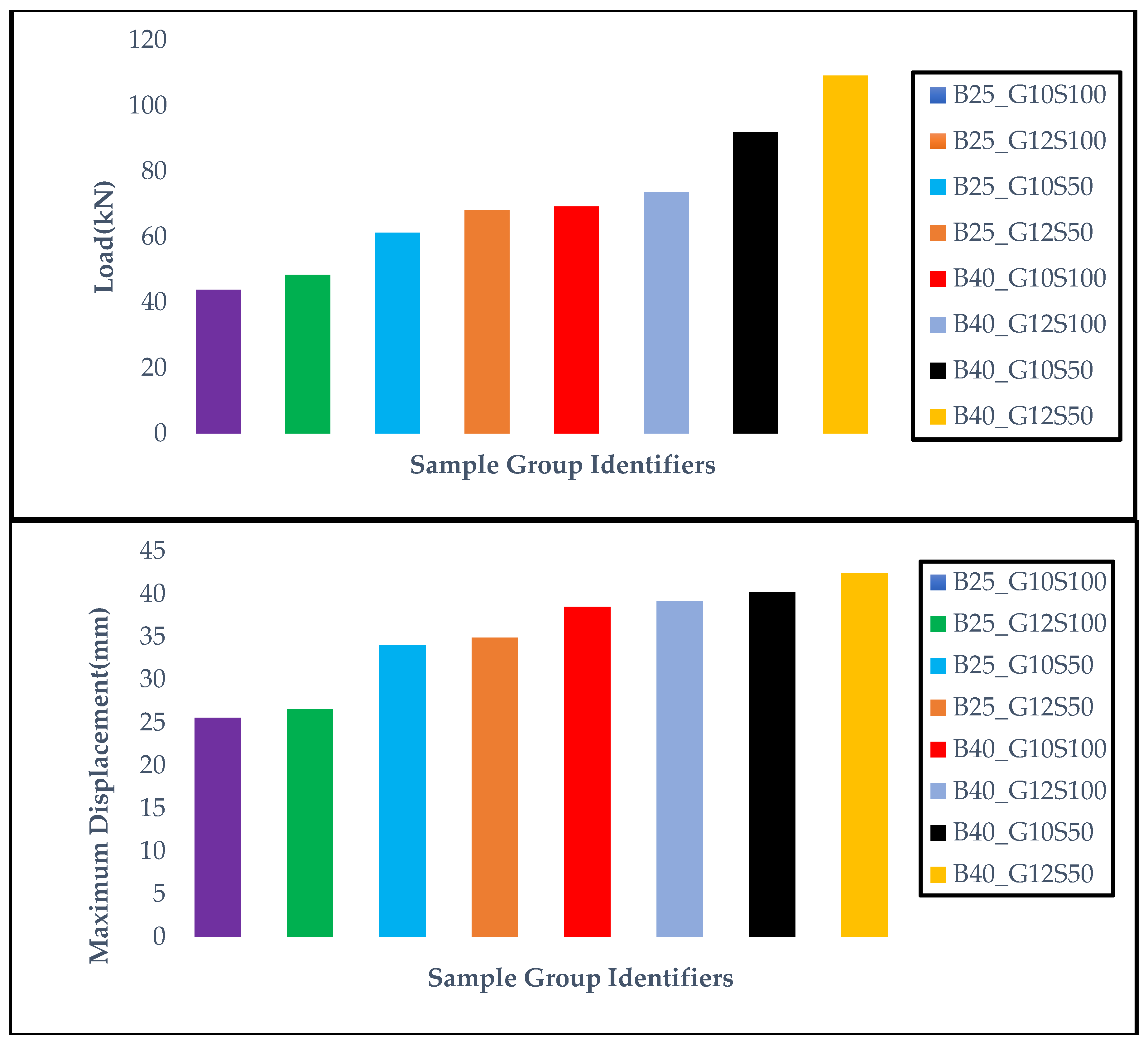
Figure 14 shows the effects of different concrete strength classes (B25 and B40) and GFRP reinforcement diameters (Φ10 and Φ12) on the load–displacement behavior of beams with a 50 mm stirrup spacing. The results obtained show that both the increase in concrete strength and the increase in reinforcement diameter significantly improve the load-carrying capacity and displacement performance. In particular, the B40_G12S50 specimen achieved the highest maximum load (109.2 kN) and the largest displacement (42.4 mm) values, clearly demonstrating the effect of the parameters on structural performance.
In
Figure 15, the effect of different concrete strength classes (25 MPa and 40 MPa) and GFRP reinforcement diameters (Ø10 mm and Ø12 mm) on load–displacement behavior is evaluated in detail. In beams with a fixed stirrup spacing of 100 mm, it was observed that both the maximum load-carrying capacity and the displacement amount increased significantly as the concrete strength and reinforcement diameter increased. For example, the B25_G10S100 specimen reached a maximum load of 43.83 kN and a maximum displacement of 25.59 mm, while the B25_G12S100 specimen, which used Ø12 mm reinforcement, reached values of 48.42 kN and 26.51 mm, respectively. Similarly, the B40_G12S100 specimen with a concrete strength of 40 MPa demonstrated the highest performance with a maximum load of 73.56 kN and a displacement value of 39.13 mm. These findings reveal that both concrete strength and GFRP reinforcement diameter have significant effects on the bending behavior of beams, demonstrating that GFRP reinforcements can provide high load-carrying capacity and ductility when configured appropriately.
When
Figure 14 and
Figure 15 are evaluated together, it is clear that stirrup spacing and concrete strength are the determining structural parameters in the bending behavior of GFRP-reinforced concrete beams. In
Figure 2, which shows beams with a stirrup spacing of 100 mm, an increase in load-carrying capacity and displacement performance was observed as the reinforcement diameter and concrete strength increased; however, this increase remained limited. For example, the B25_G10S100 specimen with 25 MPa concrete class and Ø10 mm reinforcement reached a maximum load-carrying capacity of 43.83 kN, while the B25_G12S100 specimen with Ø12 mm reinforcement reached 48.42 kN. Similarly, the B40_G12S100 specimen demonstrated the best performance with a load-carrying capacity of 73.56 kN and a displacement of 39.13 mm. However, in
Figure 1, where the stirrup spacing was reduced to 50 mm, both the load-carrying capacity and ductility performance increased significantly. In particular, the B40_G12S50 specimen exhibited the highest bending performance with a maximum load of 109.2 kN and a displacement of 42.4 mm. These findings indicate that reducing the stirrup spacing significantly enhances the energy dissipation capacity of the structural system by improving shear strength and crack control. In addition, increasing concrete strength contributes to structural rigidity by limiting the deformation tendencies caused by the low elasticity modulus of GFRP reinforcements. As a result, narrow stirrup spacings and the use of high-strength concrete are critical in optimizing the bending performance of GFRP-reinforced beams.
The structural performance of reinforced concrete beams strengthened with GFRP bars was assessed by considering key design parameters, including concrete compressive strength, longitudinal reinforcement diameter, and stirrup spacing. Among these, stirrup spacing was found to have a particularly pronounced influence on load-bearing behavior. Specifically, reducing the stirrup spacing from 100 mm to 50 mm contributed to a substantial increase in load-carrying capacity—approximately 40% in beams with C25 concrete (from 43.83 kN to 61.3 kN) and 32.7% in those with C40 concrete (from 69.25 kN to 91.9 kN). These findings highlight the critical role of transverse reinforcement in enhancing shear confinement and delaying crack propagation, thereby improving both strength and deformation capacity of GFRP-reinforced beams. Similarly, replacing Φ10 GFRP bars with Φ12 led to an increase in load capacity of approximately 11.1% (from 61.3 kN to 68.15 kN) for C25 concrete and 18.8% (from 91.9 kN to 109.2 kN) for C40 concrete. Considering the rigid nature of GFRP, these results indicate that its structural performance is significantly enhanced when used in combination with closely spaced stirrups and high-strength concrete. In particular, the combination of C40 concrete, Φ12 GFRP bars, and 50 mm stirrup spacing yielded the highest performance in terms of both load-bearing and deformation capacity.
In this context, using GFRP reinforcement in conjunction with optimized surrounding parameters offers significant advantages in terms of both load capacity and ductility. When
Table 7 and
Figure 16 are evaluated together, it is clearly seen that the maximum load-bearing and displacement performance of the beams reinforced with GFRP bars vary significantly depending on parameters such as concrete strength, bar diameter, and stirrup spacing. The graphs show that the specimen produced with C40 grade concrete, Φ12 diameter reinforcement, and 50 mm stirrup spacing has the highest load-carrying and displacement values among all groups. This indicates that the mechanical performance of GFRP reinforcement becomes more effective when considered not only as a material property but also in combination with surrounding structural parameters. The findings reveal that increasing concrete strength and applying tight stirrup spacing are critically important for achieving optimum performance in GFRP-reinforced concrete beams. Therefore, it is recommended that these parameters be optimized together in the design of GFRP-reinforced systems.
10. Conclusions
The use of GFRP reinforcement in the tension zone has significantly improved both the load-bearing capacity and ductility performance of reinforced concrete beams. Specimens reinforced with larger-diameter GFRP bars (12 mm) reached higher ultimate load values and larger displacements, thereby consuming more energy.
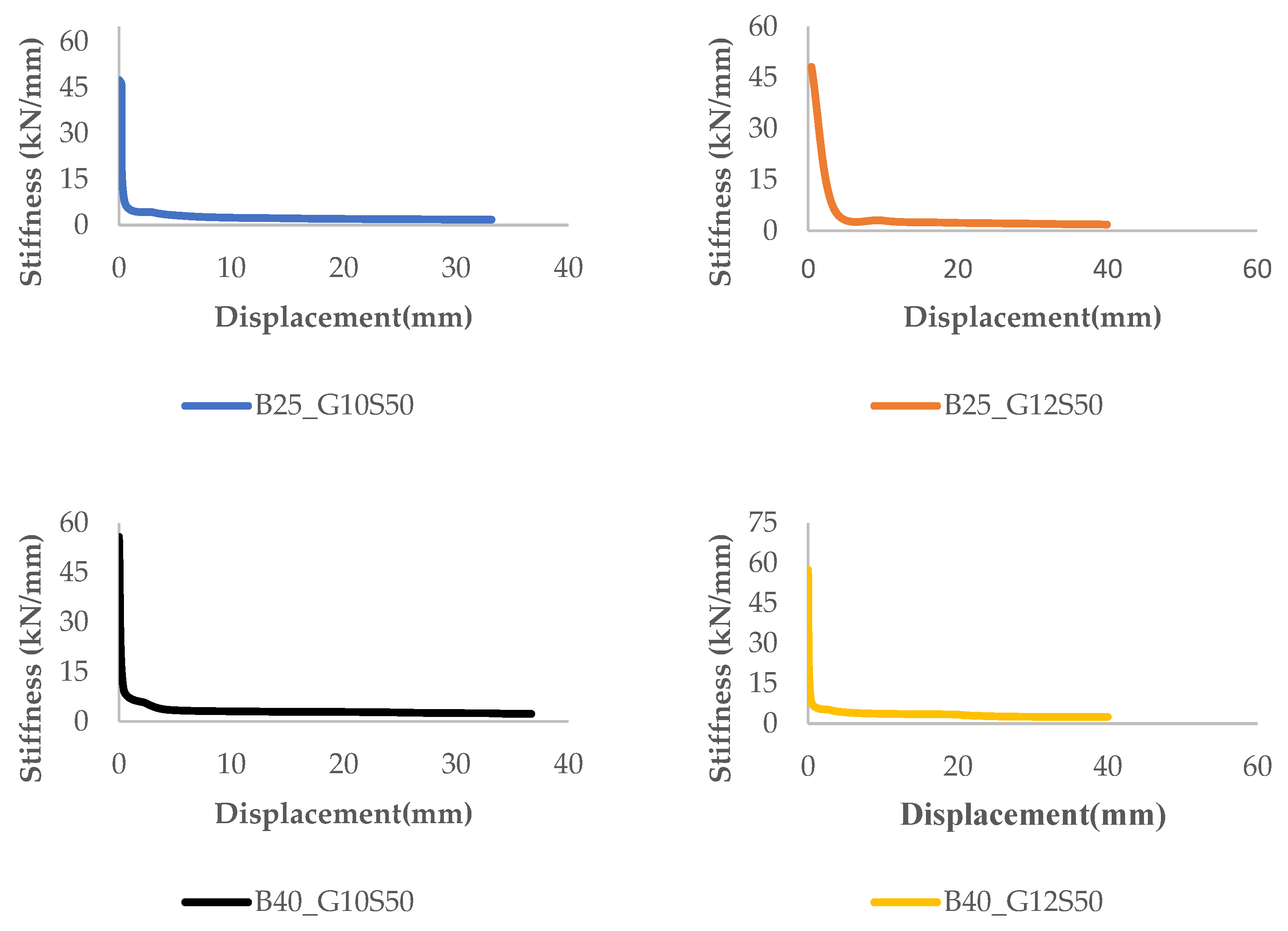
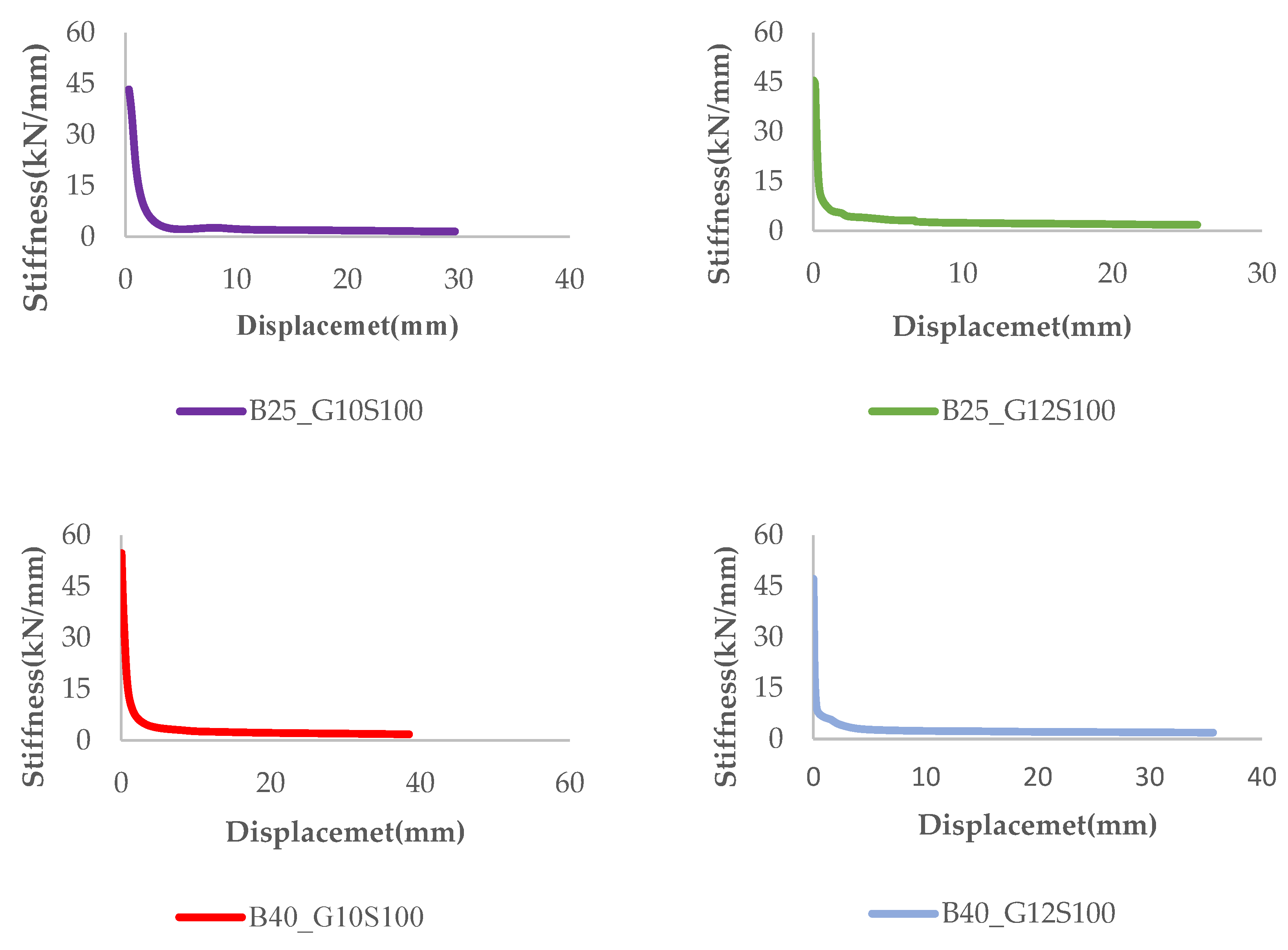
Increasing the reinforcement diameter (from 10 mm to 12 mm) enabled GFRP bars to resist tensile forces more effectively, despite their low modulus of elasticity, and resulted in a more stable reduction trend in the stiffness–displacement curves. This indicates that increasing the cross-sectional area of GFRP reinforcement leads to a notable improvement in structural performance. High concrete strength (C40), when used in combination with GFRP reinforcement, had a positive effect on the initial stiffness of the system and extended the elastic behavior region. Considering the brittle nature of GFRP, this combination was observed to enhance the deformation capacity prior to failure.
Reducing the stirrup spacing (from 100 mm to 50 mm) delayed crack formation in GFRP-reinforced beams and helped maintain structural stiffness for a longer period. This finding suggests that the effectiveness of GFRP reinforcement is not limited to the tension zone alone, but becomes more prominent within a system supported by well-configured transverse reinforcement. The stiffness–displacement curves demonstrated that initial stiffness in GFRP-reinforced beams decreases rapidly after loading begins; however, this decline can be controlled through appropriate reinforcement configuration and sufficient concrete strength.
In conclusion, the main contribution of GFRP reinforcement in reinforced concrete beams is to increase the load-bearing capacity and deformation capacity thanks to its high tensile strength. Although GFRP bars have a low elastic modulus and exhibit brittle fracture behavior, these drawbacks can be significantly mitigated through appropriate reinforcement layout, sufficient reinforcement cross-sectional area, and especially the use of high-strength concrete. Additionally, this study demonstrates that the simultaneous optimization of multiple key parameters—such as stirrup spacing, concrete strength, and reinforcement diameter—plays a decisive role in structural performance, rather than just the type of material. In particular, high-strength concrete, when used in conjunction with GFRP reinforcement, increases the system’s initial stiffness, expands the elastic behavior limit, and provides greater deformation capacity before failure. The findings clearly demonstrate that when GFRP reinforcement is used in combination with high-strength concrete and a dense stirrup arrangement, both the strength and ductility of the structural system are significantly improved, and this combination offers a safe and predictable structural design.
