Highlights
What are the main findings?
- A new approach for strengthening RC slabs was developed, employing an exterior UHPFRC jacket with a mechanical anchorage system (MAS).
What is the implication of the main finding?
- The suggested retrofitting system improved resistance to initial cracks of the slabs.
- The addition of mechanical anchorage system enhanced the bond between UHPFRC and NSC.
- The proposed strengthening technique effectively prevented early debonding.
- The finite element (FE) and analytical model outcomes exhibited a high degree of alignment with the experimental findings.
Abstract
The aim of this experimental study was to develop and evaluate the effectiveness of a new strengthening system for reinforced concrete slabs employing external jackets consisting of ultra-high-performance fiber-reinforced-concrete (UHPFRC) and mechanical anchor systems. The issue of debonding between old and fresh concrete layers, as well as the efficiency of utilizing CFRP rods, is the primary challenge of applying the UHPFRC jackets with embedded CFRP rods. In this study, we propose a novel retrofitting technique for implementing a mechanical anchor system to improve the binding of fresh UHPFRC jackets with old RC slabs. An experimental test was conducted by subjecting three slabs to cyclic loads by utilizing a dynamic actuator: a reference slab, a retrofitted slab with an external UHPFRC layer, and a retrofitted slab with an external UHPFRC layer incorporating CFRP bars. Furthermore, finite element models (FEMs) were utilized to investigate the responses of the retrofitted slabs and compare the novel method with traditional strengthening techniques, including near-surface-mounted (NSM) CFRP rods, externally bonded CFRP strips, and epoxy-bonded UHPFRC jackets, as well as two models that were the same as the experimental strengthened slab specimens except for the fact that they did not have a mechanical anchor system. Additionally, analytical mechanistic models were employed to determine the flexural moment capacity of the RC slabs. The experimental findings demonstrated that the proposed strengthening strategy considerably prevented premature debonding and enhanced the maximum load of retrofitted RC slabs by over 82%. Also, the FEM and analytical results are significantly consistent with the experimental outcomes. In conclusion, the newly suggested strengthening technique is a reliable system for enhancing the efficacy of slabs, effectively preventing early debonding between existing and new components.
1. Introduction
As a result of increased loads and environmental deterioration, the bearing capacity of reinforced concrete structures has reduced and may no longer meet service demands. Retrofitting is a commonly employed strategy for improving the structural resistance of RC elements [1]. The methods used to strengthen RC members typically involve a process of repairing and reinforcing existing structures to enhance their strength and durability and extend their service lives [2]. One often-used method of enhancing structural strength is to apply a layer of fresh reinforced or non-reinforced concrete in areas where the highest levels of stress occur. Nevertheless, the strength of structures fortified with normal-strength concrete (NSC) reduces over time [3]. This issue has provoked investigations into the use of advanced cementitious compounds to enhance structural concrete components. Ultra-high-performance fiber-reinforced concrete (UHPFRC) is a recently developed construction material that possesses exceptional compressive and tensile strength along with remarkable durability. This makes it highly desirable for many strengthening purposes [3,4,5,6,7,8,9,10]. The limited quantity of coarse aggregates, combined with a significant proportion of fibers (often 2 or 3% by volume), results in enhanced stiffness, strength, and flexibility [11]. In addition, UHPFRC has compressive and tensile strengths above 150 MPa and 7 MPa, respectively, surpassing those of normal strength concrete (NSC) [12]. Over the past few decades, there has been a great deal of research undertaken to examine the responses of RC elements that have been strengthened using UHPFRC, either through experimental work or numerical simulation studies [12,13,14,15,16,17]. Nevertheless, in most of these investigations, UHPFRC was utilized as a means of reinforcing existing RC structures. This was achieved either by pouring fresh UHPFRC layers or by attaching precast UHPFRC layers using epoxy glue [18,19,20,21]. Ahmed et al. [22] studied the flexural responses of reinforced concrete beams reinforced in the tension zone with a fresh UHPFRC jacket. Additionally, the researchers constructed a 3D model using finite element simulation. Before the pouring of the fresh UHPFRC layer, the bottom sides of the beams were roughened to a depth of around 2.5–5.0 mm. The FE model employed the surface-to-surface contact technique to facilitate interaction between the beam and UHPFRC layer. The outcomes demonstrated that the strengthened beams showed notable enhancements in stiffness, maximum load, and energy absorption. Yang et al. [23] investigated the use of a steel-reinforced UHPFRC jacket, a GFRP-reinforced UHPFRC layer, and a CFRP mesh to enhance the strength of pre-damaged full-scale hollow RC slab beams. The findings were derived by using a numerical analysis employing an implicit solution. A concrete-damaged-plasticity model (CDPM) was employed for simulating the UHPFRC. The tie approach was employed to depict the interaction between the CFRP mesh and the preexisting concrete. It was found that the finite element model neglected to account for the bond-slip that occurred between the individual components. The findings indicated a significant improvement in the maximum flexural capacity of the hollow slab beam when reinforced with a GFRP-reinforced UHPFRC layer and CFRP mesh, with increases of 47.1% and 41.2%, respectively. Zhang et al. [24] used a UHPC jacket to strengthen damaged RC beams. After subjection to preـdamage, the bottom faces of RC beams were cut to expose the coarse aggregate, which was then drilled to a 12 mm diameter and a 90 mm depth. High-strength bolts were then installed, and the holes were cleaned and filled with epoxy adhesive. The results showed the reinforced beam substantially increased crack resistance and maximum bearing capacity. Yoo et al. [25] examined the impact ratio of reinforced steel and steel fibers with respect to UHPC beams, indicating that rebar steel and steel fibers effectively enhanced crack-widening resistance and ductility. Based on the results obtained by Lampropoulos et al. [26], strengthening RC beams by placing UHPFRC layers at different places significantly improves both the ultimate moment capacity and yielding force for each of the reinforced beams. The corresponding investigations revealed that UHPC jacket thickness and the kind of retrofitting method employed have a substantial influence on stiffness, failure mode, ductility, and beam capacity [27]. RC slabs were strengthened with UHPFRC layers and reinforcing steel embedded within the UHPFRC. Testing was conducted, employing three-point loading. The findings indicated the generation of diagonal cracks in the RC slabs, observed as de-bonding in the interface contact between the UHPFRC and NSC layers, as documented by Yin et al. [28]. According to the conclusions of one study [20], slipping in the interaction between UHPFRC and NSC layers appeared during the loading process. Paschalis and Lampropoulos [29] used dowel connectors between the NSC and UHPFRC to prevent early debonding. Their study evaluated the effectiveness of employing a UHPFRC jacket on three sides. They found that employing UHPC jackets without the connectors (dowels) was efficient up to the limit of serviceability, at which point excessive slip values resulted in debonding and reduced beam capacity. Applying dowels increased the bond between the two concrete layers. Additionally, dowels inhibited the expansion of cracks in the tension zone of the beams. Said et al. [30] studied the impact of the strengthening technique, the ratio of fiber, and the thickness of the jacket on the strength shear of RC beams strengthened with a UHPFRC jacket. Direct pouring of UHPFRC (cast in situ) on the beam substrate enhanced the beam’s ductility, load capacity, and toughness to a greater extent than the anchoring approach. It increased the thickness of the strengthening layer of UHPFRC and the steel fiber ratio and enhanced beam ductility and strength. Qsymah et al. [31] examined two-way RC slabs strengthened with FRP subjected to flexural loading using FE analysis. The outcomes demonstrated that CFRP provided the greatest strength improvement in the maximum load, with 34.5%. Nevertheless, the different methods of reinforcement are even subject to challenges associated with the debonding of the existing components and the attached reinforcement system [26,27,28]. Premature debonding between the components of strengthening systems and existing RC members poses a significant hazard to their effectiveness, particularly when subjected to periodic loads and vibrations. In addition, as mentioned in the above literature, there is a great deal of research on the rehabilitation of reinforced concrete members using various strengthening techniques, but there is a lack of research comparing various traditional and recent techniques. The newly proposed strengthening method is designed to efficiently and permanently overcome the challenges and constraints affecting earlier strengthening methods, especially the problem of premature debonding. This study proposes a novel retrofitting technique for implementing a mechanical anchor system to improve the binding of fresh UHPFRC jackets with old RC slabs. The objectives of this study were to assess the structural performance of slabs strengthened with the newly proposed system and evaluate the influence of CFRP rods on the behavior of the strengthening slab when the proposed system is under cyclic load. The strengthening system consists of CFRP rods, a UHPFRC layer, and mechanical anchor systems. The system’s effectiveness was assessed using experimental testing under half-cyclic load conditions. The proposed strengthening technique was compared with different traditional reinforced techniques through developing finite element models (FEMs), namely, near-surface-mounted (NSM) CFRP rebars, externally attached CFRP strips, and UHPFRC jacket bonding with epoxy adhesive, as well as two models that were the same as the experimental strengthened slab specimens except for the fact that they did not have a mechanical anchor in order to evaluate the influence of a mechanical anchor system on the behavior of the strengthening slabs. Additionally, analytical models were designed to demonstrate the behavior of the slabs and then compared with the results from experimental and finite element (FE) studies.
2. Developing a New Strengthening Technique for Slabs
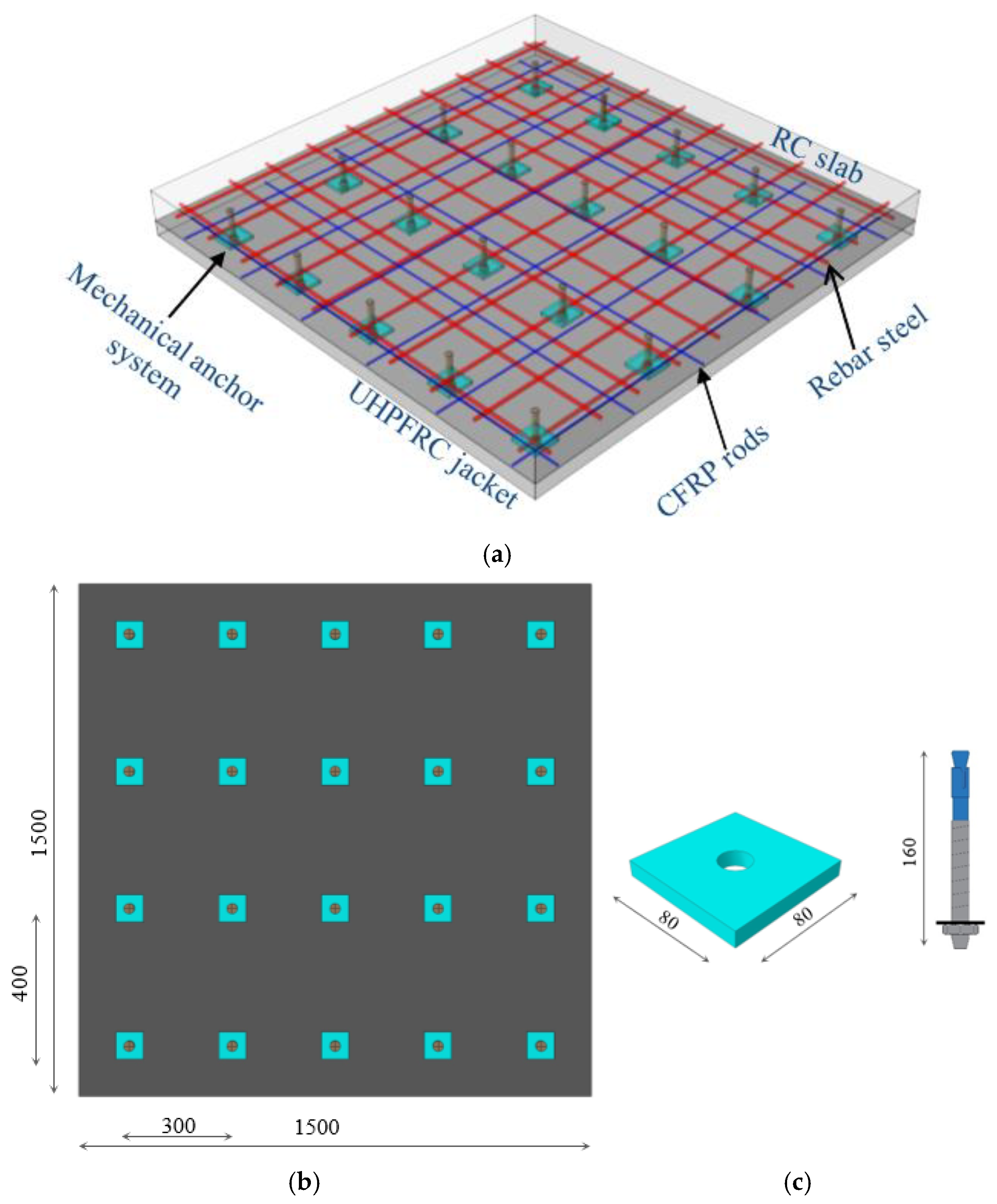
The proposed retrofitting approach relies primarily on three components: CFRP rods for augmenting the flexural capacity; UHPFRC jacketing for establishing a robust connection with the RC slabs, minimizing the risk of delamination or early debonding due to its superior bonding characteristics and protecting the CFRP bars from external adverse effects; and a mechanical anchor system for attaching the fresh UHPFRC jacket to the RC slab. Figure 1 illustrates all the details and components of the suggested strengthening system.
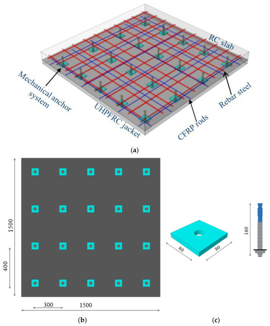
Figure 1.
Details of the strengthening method (dimensions are given in mm): (a) components of the proposed retrofitting system; (b) bottom view of slab; and (c) mechanical anchorage system components.
CFRP rods were used in this study due to their higher elasticity modulus, which allows them to generate fewer distortions under cyclic loading than steel bars. In this study, the UHPFRC jacket was reinforced with CFRP bars to increase the slab’s flexural capacity. Furthermore, CFRP rods’ lightness, strength, and corrosion resistance make them an adaptable and useful option for enhancing the efficiency and durability of RC elements. The CFRP bars measured 1440 mm in length and 8 mm in diameter. They extended roughly 30 mm from the edge of the mold in each direction, as depicted in Figure 1. The positioning of the CFRP bars was meticulously coordinated to avoid any interference with the arrangement of the bolts. Steel nails were employed to affix the CFRP rods to the underside of the slab.
Ultra-high-performance fiber-reinforced concrete (UHPFRC) is a highly advanced cement-based material that was developed to improve the strength of flexural RC structures. The basic materials used in UHPFRC include cement, quartz powder, silica fume, quartz sand, steel fibers, and superplasticizers.
Figure 2 shows the proposed steel fiber used in the experimental work. Due to their high compressive and tensile strengths, in the currently proposed system, the external UHPFRC jackets are utilized to transfer stress (load) from the NSC layer to the CFRP rods, with a reduced environmental impact on the CFRP rods. Choosing and applying the appropriate thickness of UHPFRC are important factors pertaining to the proposed system. Increasing the thickness of the UHPFRC jacket in the strengthening system enhances the system’s ability to resist punching shear [32] and reduces shear stress in critical areas of the RC slab. Figure 3 demonstrates the main specifications of geometric slabs.
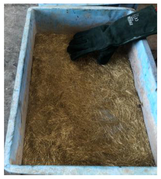
Figure 2.
Steel fiber used in this study.

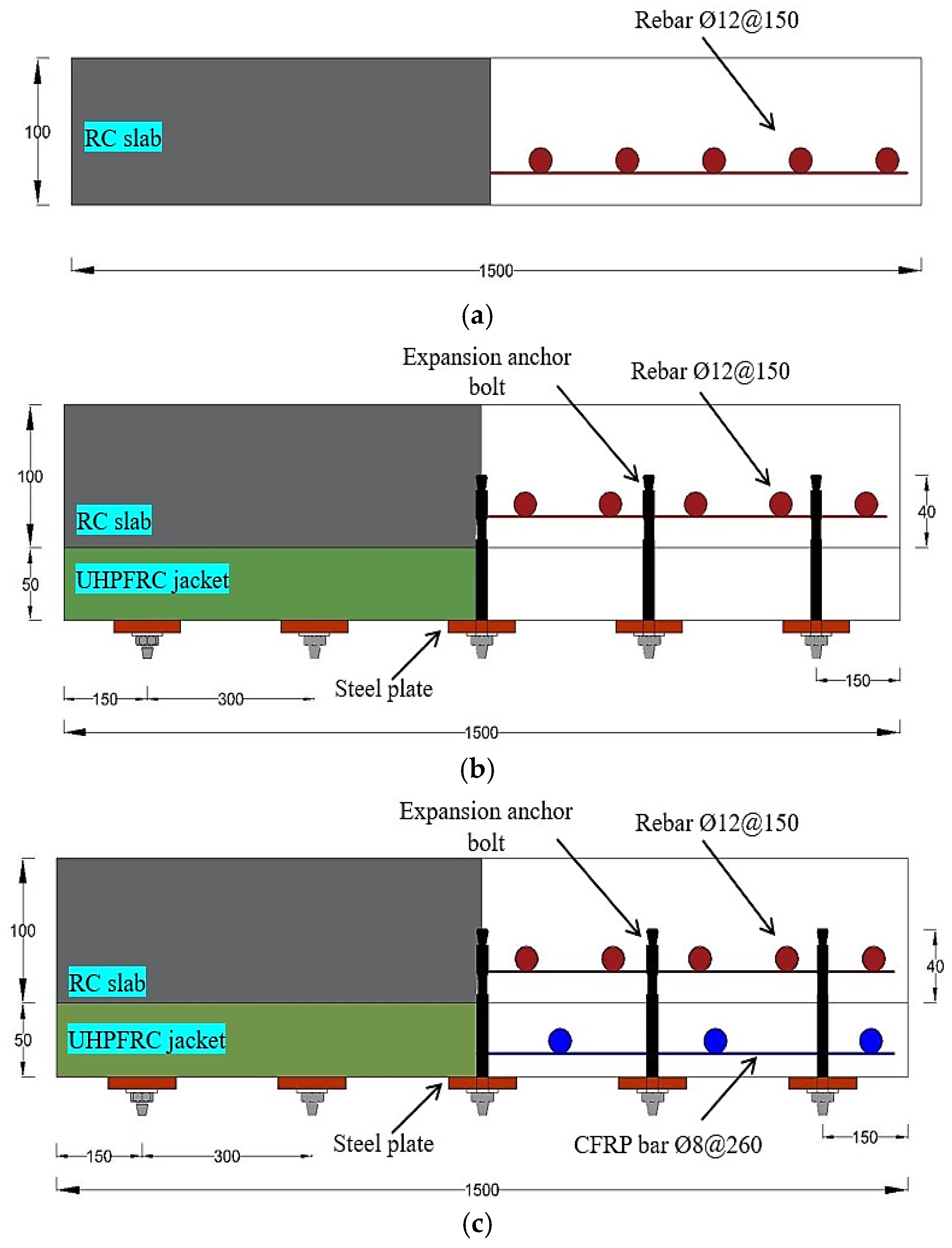
Figure 3.
Main details of slab specimens (dimensions are given in mm): (a) control slab (SB1); (b) strengthened slab (SB2); and (c) strengthened slab (SB3).
Therefore, the suggested jacket thickness for UHPFRC is 50 mm, which effectively enhances the load-bearing capacity and performance of the RC slab. Additionally, this thickness ensures there is enough protection for the CFRP mesh, as depicted in Figure 3.
The mechanical anchor systems in this study have two main components: expansion anchorage bolts and a high-steel plate. The interface contact that occurs between the slabs and the UHPFRC jackets depends on the anchor system and the distance between the slabs and jackets, so these factors should be selected appropriately. Therefore, to ensure secure binding and fulfil the necessary resistance requirements, we used a 160 mm long mechanical expansion anchor bolt that was 12 mm in diameter, with a distance from the mechanical anchorage system of 400 × 300 mm in the two opposite directions, as demonstrated in Figure 1. Twenty 40 mm deep expansion bolts were implanted into the undersurface of each specimen. Furthermore, the presence of a high-steel plate in the mechanical anchor system allowed for an even distribution of applied forces across the RC slab surface and prevents localizing stress concentrations, reducing the possibility of early failure and deformation of the slab. The steel plates were designed according to ASTM A29 [33]. The steel plates had dimensions of 80 × 80 mm and were 10 mm thick, with a 12 mm circular hole in the center. Figure 4 provides a workflow of the steps of the newly proposed strengthening technique.
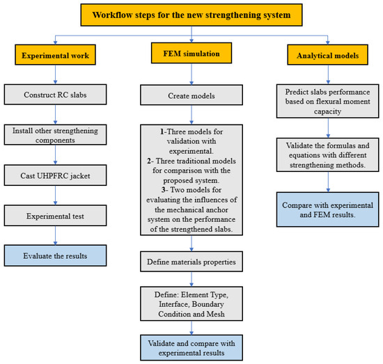
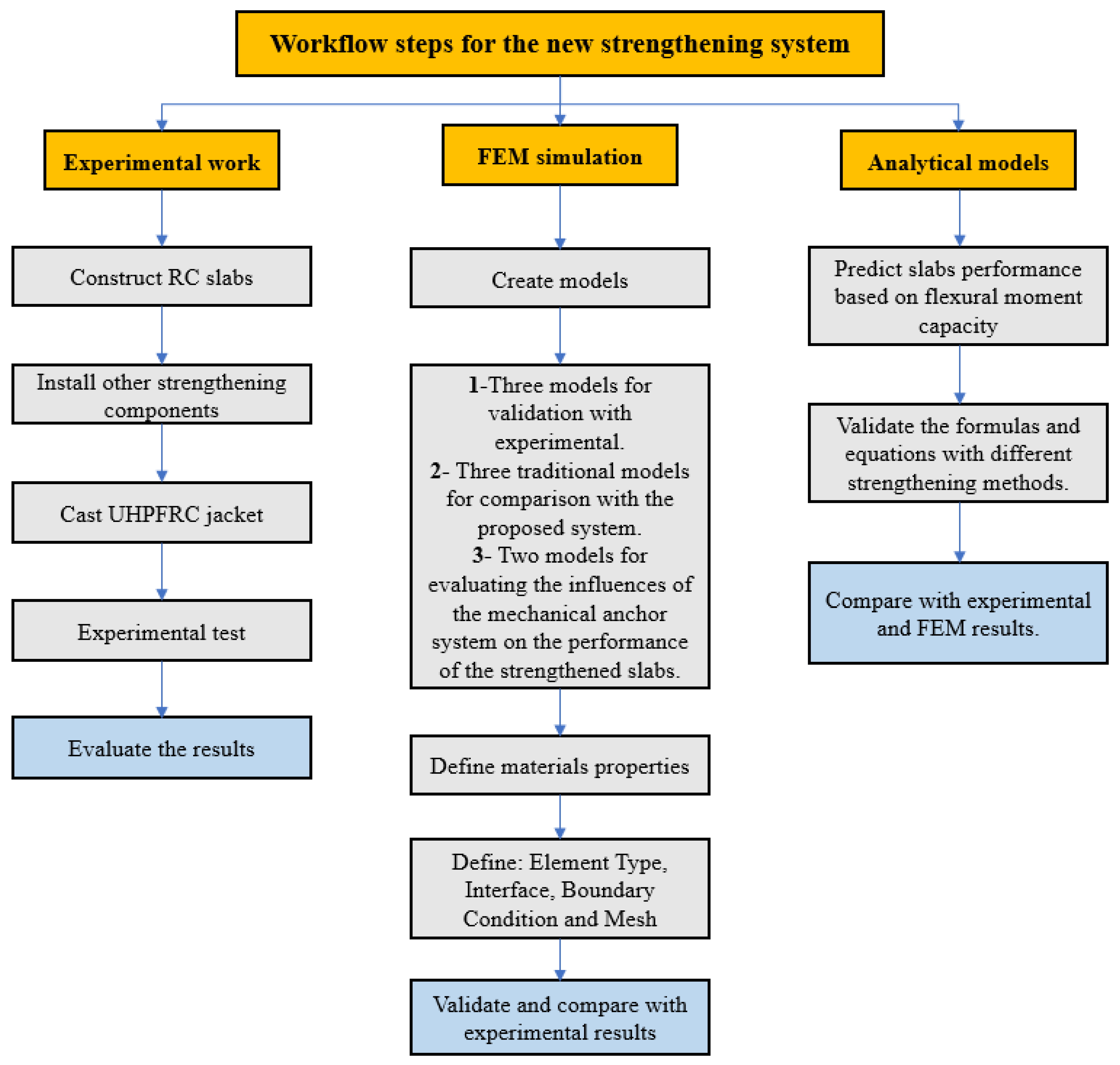
Figure 4.
Main processes involved in the new strengthening technique.
3. Experimental Program
3.1. Slab Specimen Design
The experimental research included one control slab (SB1) and two RC slabs (SB2 and SB3) strengthened by the UHPFRC layer in the tension zone. The external UHPFRC jacket of the strengthened SB3 slab was reinforced using CFRP rods. As plotted in Figure 3, the dimensions of the slabs were 1500 × 1500 × 100 mm, with an effective length of 1300 mm. The reinforced concrete slabs are designed according to EC2 and ACI-318-08. SB2 and SB3 were jacketed with a 50 mm thick exterior UHPFRC layer. A 12 mm monolithic steel reinforcing mesh was used, with an effective depth of 75 mm. The effective depth of the expandable anchor bolts was 90 mm, with 40 mm implanted inside the NSC layer and 50 mm in the UHPFRC jacket, as shown in Figure 3. The mechanical anchorage system was placed a distance of 400 × 300 mm away in the two opposite directions. The slabs were built and subjected to incremental periodic (half-cycle) loads.
3.2. Properties of Materials
A local manufacturer provided us with single-patch ready-mix concrete (C30/37) for casting all the pre-existing slabs in this investigation. The maximum aggregate diameter was 14 mm, with a w/c ratio of 0.44. The RC slabs were reinforced with 12 mm diameter steel bars (B500B) that had a 600 MPa yield strength and a 210 GPa elastic modulus. We employed steel fibers of 20 mm in length that possessed a tensile strength above 2500 MPa, as seen in Figure 2. A fully automatic mixer with a compressive strength of 144 MPa under ACI 239R-18 was used to manufacture the UHPFRC. Table 1 displays the mixing proportion of Dura UHPFRC. Furthermore, 8 mm diameter CFRP bars (Carbo Dur ® BC8) were employed in the jacket of the SB3 slab. They had a 2500 MPa tensile strength, 153 GPa Young’s modulus, and a 0.2 Poisson’s ratio [34]. The CFRP bars (CarboDur® BC8) consist of a carbon-fiber-reinforced polymer (CFRP) with a high-performance epoxy matrix, while the mechanical anchor system was assembled from a steel plate produced in a local workshop using S50C steel and HAS-BW M12 expansion anchoring bolts [35]. Table 2 illustrates all the properties of the materials used in this study.

Table 1.
Mixing proportions of UHPFRC.
3.3. Slabs Casting
The RC slab specimens were fabricated in the Material and Structural Laboratory of the Engineering Faculty of the University of Putra Malaysia. After the reinforcing rods were placed in the mold and the strain gauges were attached to the middle of the steel reinforcement, the specimens were prepared for pouring. Figure 5 shows the entire process of pouring the RC slab specimens. A 5 mm strain gauge was utilized for the reinforcing steel and CFRP bars. To safeguard the strain-gauge from damage during the casting operation, an extra coating of silicone material was used as a protective layer. The expansion anchor bolts were employed with the determined size to provide suitable bonding strength. Once the concrete slabs’ cure time had elapsed (after 28 days), the expansion anchor bolts were securely attached at a depth of 40 mm to the underside of the slabs by drilling holes and then embedding the bolts using a hammer [36], as shown in Figure 5. The casting of the UHPFRC jackets was performed manually using a fully automatic mixer, following the attachment of the expansion bolt on the underside of the RC slabs. Once the UHPFRC had hardened (after 28 days), the square steel plates were attached to the underside of the UHPFRC layer, as illustrated in Figure 5.
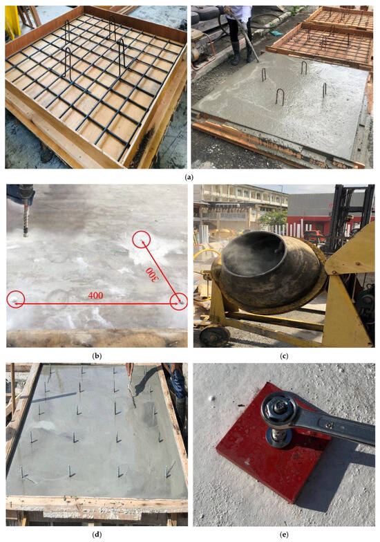
Figure 5.
Process of casting the slabs: (a) preparing the specimens and casting; (b) drilling the holes for expansion anchor bolts; (c) mixing the UHPFRC; (d) casting the UHPFRC; and (e) attaching the steel plate.
Table 2.
Properties of materials used in this study.
Table 2.
Properties of materials used in this study.
| Item | Characteristics | |
|---|---|---|
| NSC | Mean compression strength (MPa) | 34.8 |
| UHPFRC | Mean compression strength (MPa) | 144.2 |
| Reinforcing steel | Yield strength (MPa) | 600 |
| Elasticity modulus (GPa) | 210 | |
| Poisson’s ratio | 0.25 | |
| Density (kg/m3) | 7850 | |
| CFRP [34] | Fiber content (%) | >68% |
| Tensile strength (MPa) | 2500 | |
| Elasticity modulus (GPa) | 153 | |
| Poison’s ratio | 0.2 | |
| Expansion bolt [35] | Tensile strength (MPa) | 700 |
| Yield strength (MPa) | 560 | |
| Elasticity modulus (GPa) | 206 | |
| Poison’s ratio | 0.28 | |
| Steel plate | Yield strength (MPa) | 425 |
| Elasticity modulus (GPa) | 207 | |
| Poisson’s ratio | 0.29 | |
| Density (kg/m3) | 7860 | |
| Adhesive mortar [37] | Compressive strength (MPa) | 63 |
| Tensile strength (MPa) | 39 | |
| Elasticity modulus (GPa) | 4.48 | |
| Poisson’s Ratio | 0.37 |
3.4. Experimental Testing
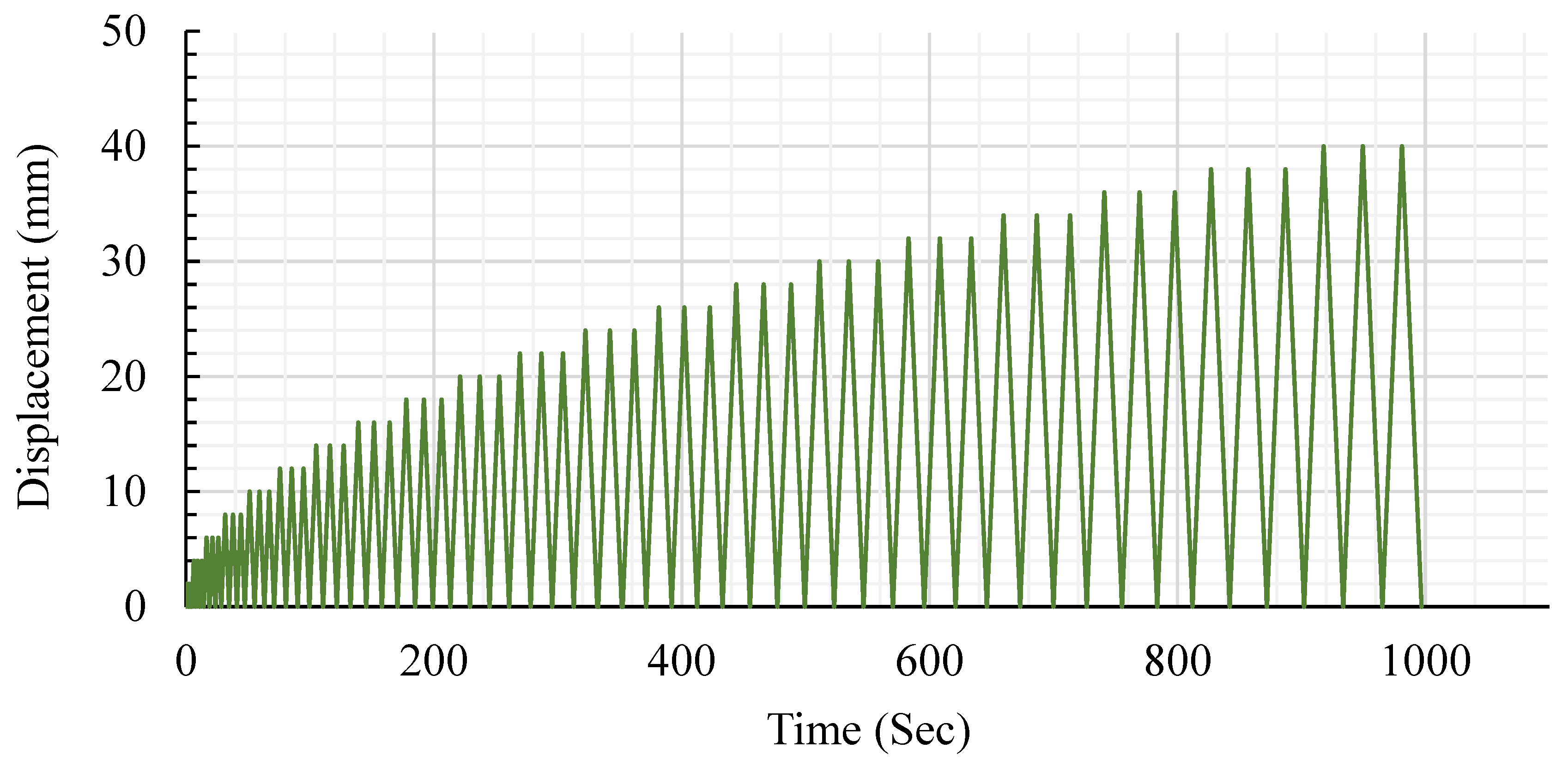
Figure 5 depicts the setup and instruments pertaining to the testing specimens. As shown in Figure 6, we used three electronic linear variable differential transducers (LVDTs) at the center to estimate the deflections of the slab at each quarter. The slabs were supported by square steel plates measuring 200 × 200 mm on all four edges. The distance between each support was 1300 mm, measured from center to center. A hydraulic actuator jack (MTS) equipped with a valve servo capable of withstanding loads exceeding 1000 KN was utilized to apply a periodic load (half-cyclic load). The actuator jack was actuated using a Shimadzu-4830 servo smart controller. Furthermore, cyclic loads were applied on a square steel plate in the upper middle of the RC slabs, as depicted in Figure 6. The load was generated through the application of pushing and releasing phases, enabling the loading cell to revert back to its original position at an equivalent loading rate. The loading methodology for the slab was determined based on the guidelines set by the ACI Committee 374.1-05 (ATC-1996). To achieve a consistent response, the displacement was iteratively repeated three times, and a loading rate of 2 mm/s was applied. Figure 7 illustrates the half-cyclic loading protocol.
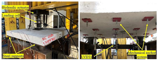
Figure 6.
Test setup and instruments applied to specimens.

Figure 7.
Half-cyclic loading protocols.
4. Finite Element Modeling Program
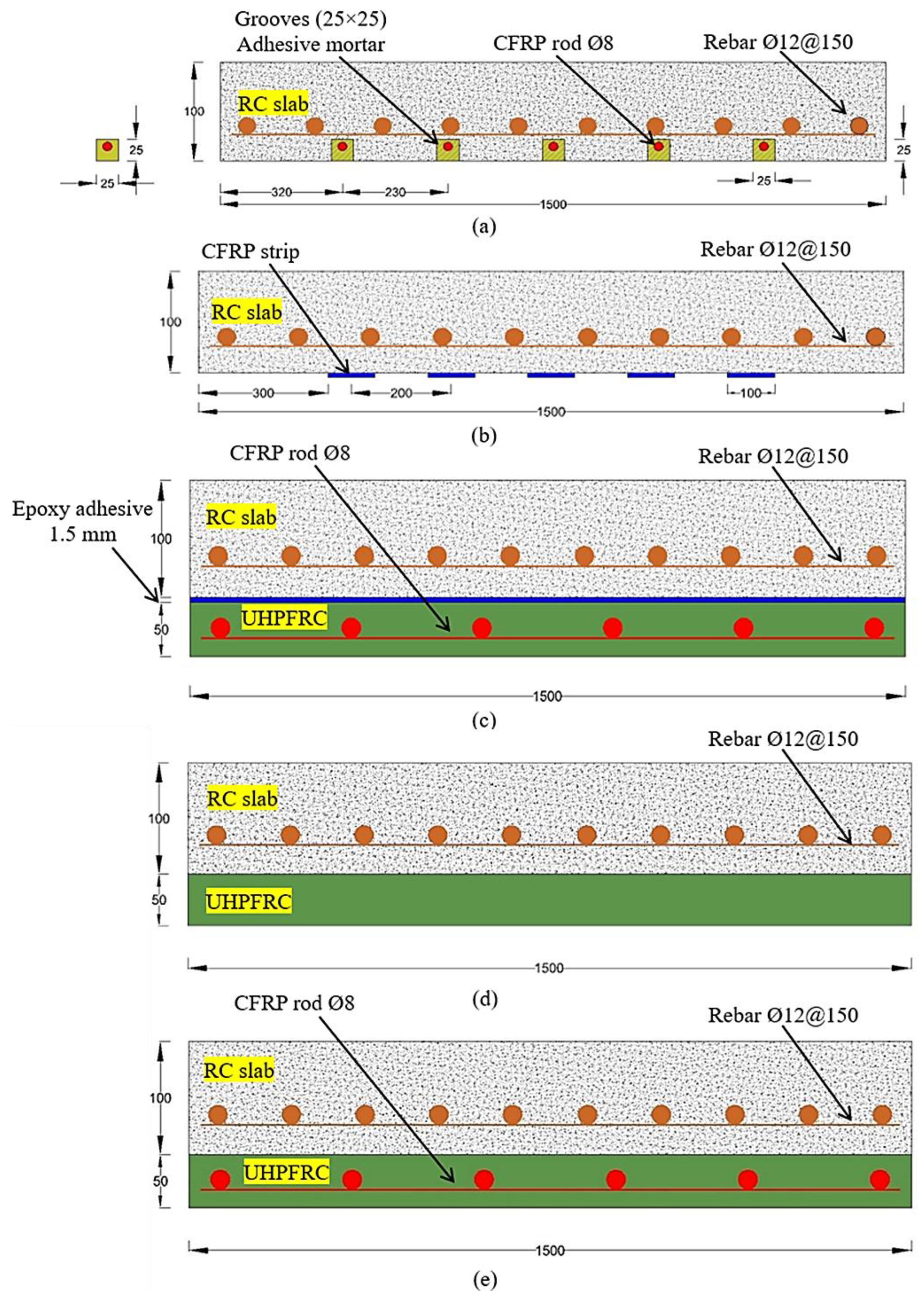
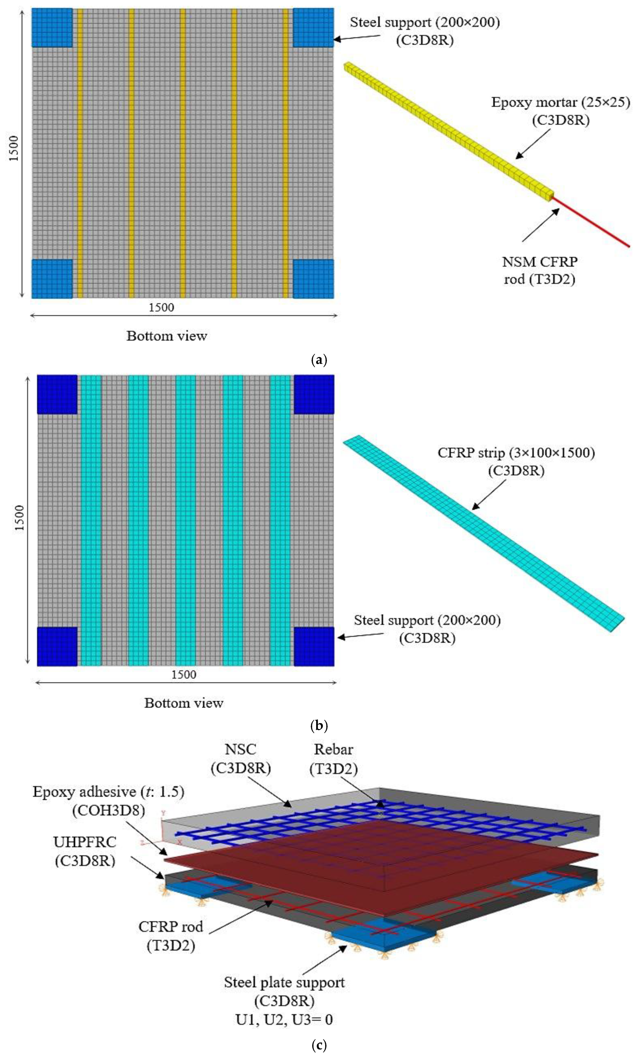
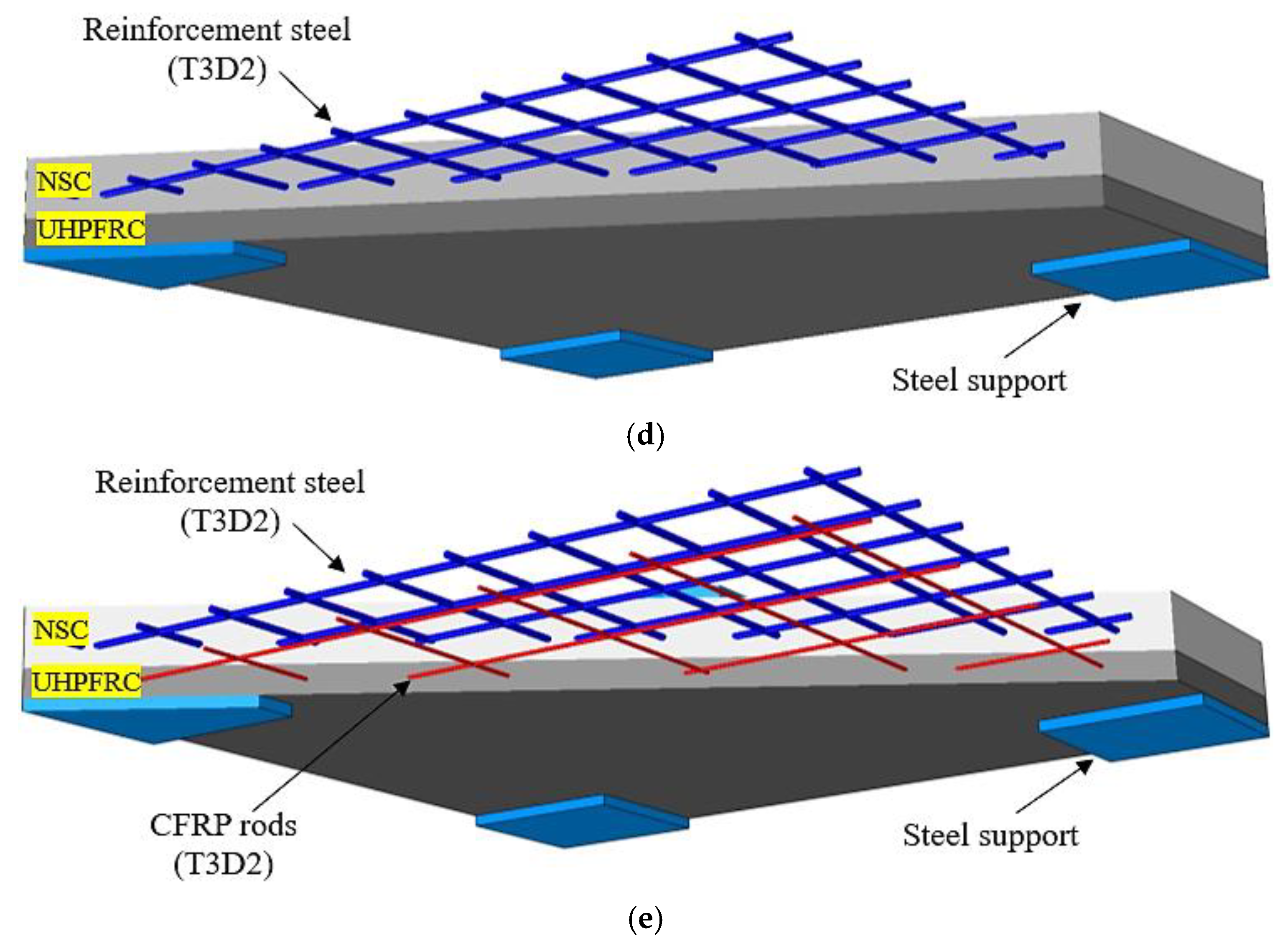
Abaqus software [38] was employed to create 3D finite element models capable of simulating the cyclic responses of the strengthened concrete slabs, employing the exterior UHPFRC layer and mechanical anchor systems. We also investigated the effectiveness of the suggested strengthening strategy versus the traditional strengthening techniques under cyclic loading conditions. The application of non-conventional transverse reinforcement, such as fiber-reinforced polymer (FRP) sheets, strips, bars, and ropes, to enhance the structural performance of reinforced concrete (RC) slabs and shear-critical components has been prevalent in recent decades [39,40,41,42]. Techniques for strengthening RC members by using FRP sheets or strips have been extensively utilized for the flexural and shear strengthening of reinforced concrete elements (slabs, beams, and columns), significantly improving load-bearing capacity and ductility [43,44]. In addition, FRP ropes made from twisted or braided fibers have attracted interest lately for their capacity to offer enhanced anchoring and confinement, making them especially beneficial in retrofitting applications [45,46]. Therefore, different strengthening technique models were developed using finite element (FE) models. The proposed strengthening technique was compared to the near-surface-mounted (NSM) CFRP rebar method, the externally attached CFRP strip technique, the use of a UHPFRC jacket with CFRP rod bonding using an epoxy adhesive, and external jacketing of the UHPFRC without a mechanical anchor system. The strengthened slabs modified using these different strengthening techniques were designed based on the experimental study in terms of the geometric details and the materials’ mechanical properties. A nonlinear analysis of materials was employed in this study [38]. The details of the strengthening techniques are displayed in Figure 8. The NSM method involved the placement of 5Ø8 mm NSM CFRP rebars in grooves within the slab, which were then filled with adhesive mortar according to ACI 440.2R-17 [47]. The adhesive mortar filling serves as the conduit for transmitting stress (loads) between the CFRP rod and the NSC layer. The grooves in the concrete cover of the slab had dimensions of 25 × 25 mm [37]. For the approach involving externally attached CFRP strips, five CFRP strips measuring 100 mm and 3 mm in width and thickness, respectively, were utilized [34]. The strips were affixed to the tension zone of the RC slab, with 200 mm of space between the two strips. The third strengthening strategy involved the utilization of CFRP rods embedded within the UHPFRC jacket using epoxy adhesive bonding. The jacket had a thickness of 50 mm, and the thickness of the epoxy adhesive was assumed to be 1.5 mm. Lastly, two models that were the same as the SB2 and SB3 experimental slab specimens except for the fact that they did not have a mechanical anchor system were developed to assess the impact of the mechanical anchor on the performance of the strengthened slabs. In addition, the adhesive mortar properties used in the FEMs for specimens SB-N and SB-E are shown in Table 2. Table 2 shows the mechanical characteristics of all the materials employed in the numerical investigation, and Table 3 provides the main details of the strengthened slabs.

Figure 8.
Details of strengthening slab techniques (note: all dimensions are in mm): (a) near-surface-mounted (NSM) CFRP rods; (b) attached CFRP strips; (c) externally jacketed UHPFRC using epoxy adhesive bonding, and (d,e) externally jacketed UHPFRC without a mechanical anchor.
Table 3.
Details of slab specimens.
4.1. Concrete Constitutive Model
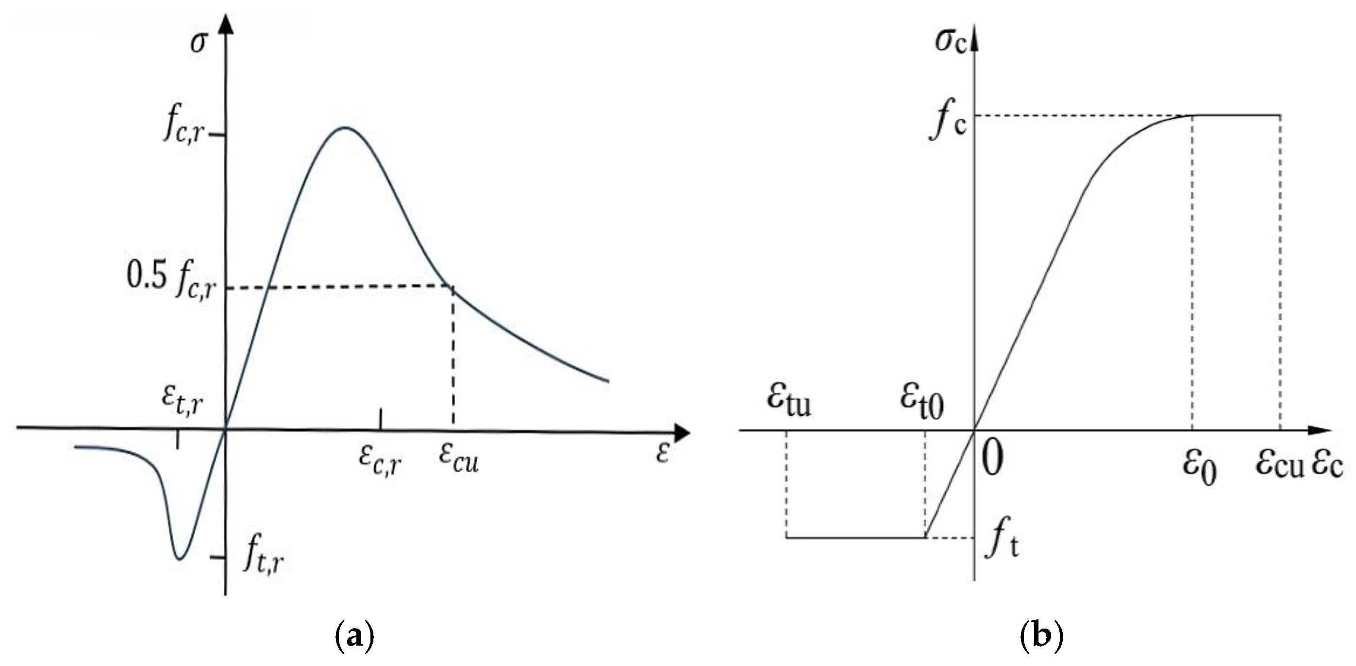
In this research, we utilized the concrete damage plasticity model (CDPM) to assess the non-linear characteristics of NSC and UHPFRC under both tension and compression. Figure 9 illustrates the relationship between the stress and strain of the NSC-UHPFRC materials when subjected to compression and tension. The elasticity modulus and tensile strength for the NSC and UHPFRC were determined according to ACI 318-19 [48], employing Equations (1) and (2). Based on the Design Concrete Structures Code (GB 50010-2010) [49], the constitutive stress–strain relationships of NSC under uniaxial tension and compression were calculated using Equations (3)–(6). Furthermore, the approach used by Jia et al. [50] was employed to calculate the compression and tensile stress–strain of the UHPFRC using Equations (7) and (8). Based on the ABAQUS user manual [38], NSC and UHPFRC stress–strain relationships should be converted to stress–inelastic strain using Equations (9) and (10) in order to determine the inelastic strain. Equations (11) and (12) were utilized to calculate the damage parameters of concrete in terms of the compressive and tensile strengths for the NSC and UHPFRC [51]. Table 4 demonstrates the mechanical characteristics of the NC and UHPFRC that were used in this study. In addition, in the concrete-damaged plasticity models for the NC and UHPFRC layers, the following parameters were assumed: the viscosity value is 0.0001, the dilation degree is 36°, the possibility of flow eccentricities is 0.1, the ratio of the stress of the integral on the tension to the compressive diagonal is 0.667, and the force-at-yield proportion with a similar axial compressive force to the initial yield force under unilateral compression is 1.16 [22,51].
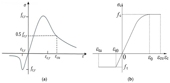
Figure 9.
Stress–strain curves for compression–tension properties of (a) UHPFRC and (b) NSC.
Table 4.
Mechanical characteristics of NSC and UHPFRC.
The elasticity modulus and tensile strength for the NSC and UHPFRC can be determined using the following equations [48]:
Accordingly, the constitutive stress–strain properties of NSC under uniaxial tension and compression can be obtained through the following equations [49]:
The compression and tensile stress–strain properties of UHPFRC can be calculated using the equations below [50]:
Consequently, the stress–inelastic strain relationship can be determined using the following equations [38]:
Lastly, the damage parameters of concrete under compressive and tensile force can be calculated using the equations provided below [51]:
and denote the tensile and compressive strength of NC; indicates the NC tensile strain corresponding to ; denotes the NC compressive strain at ; indicates the elastic modulus; and indicate the tensile and compressive factors of NC; and denote the strength of UHPFRC (compressive and tensile); denotes the equal secant modulus in the maximum state; and denote the ultimate compressive and tensile strain of UHPFRC; and denote the peak compression tension and strain; and indicate the NC parameters of damage under tension and compression, respectively; and indicate the stress under compression and tension; and denote the plastic strain linked with the tensile and compressive stress, respectively; and are invariant with ranges (
4.2. Steel, CFRP, and Epoxy Adhesive Mortar Models
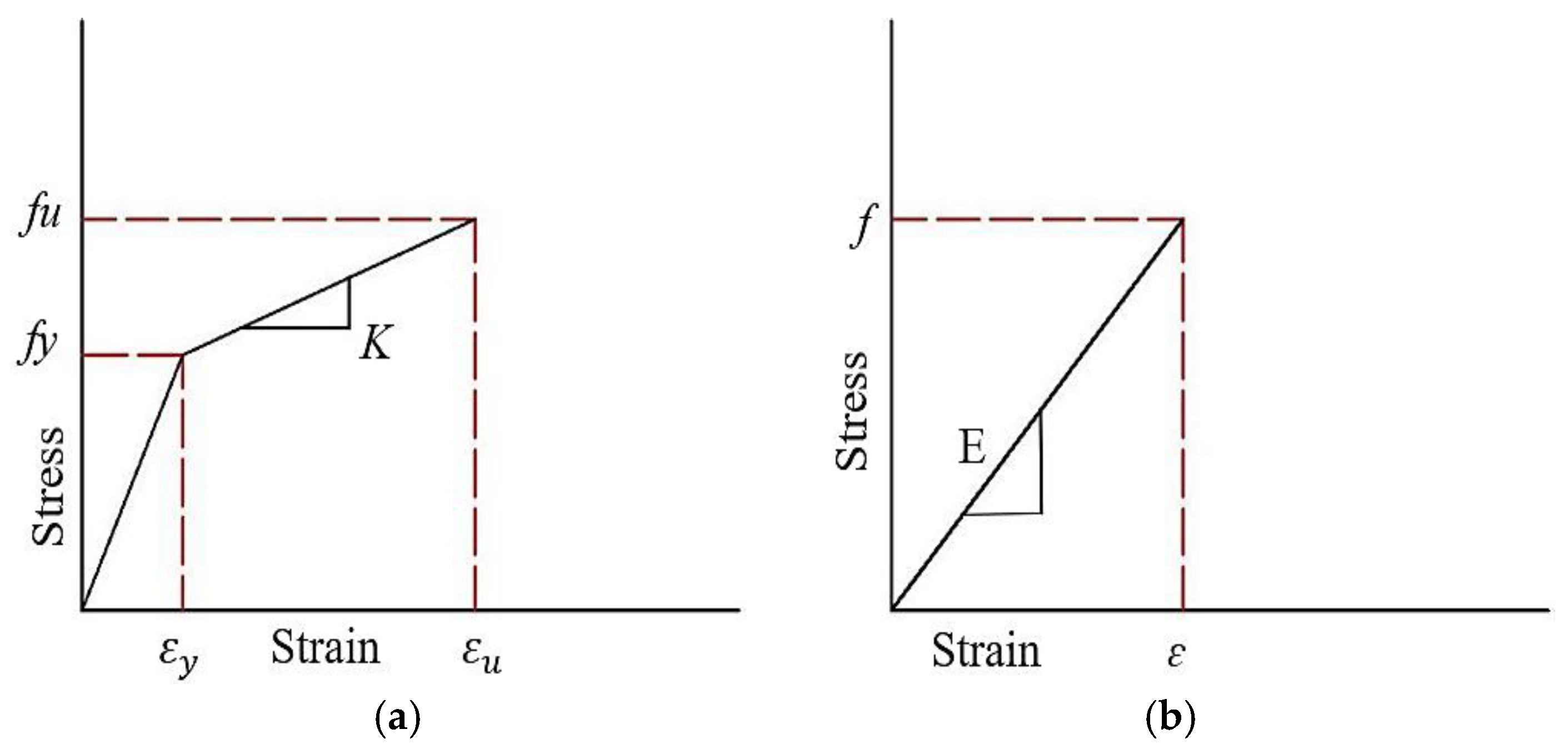
Figure 10 displays the stress–strain relationship regarding the reinforcing steel and CFRP (bars and strips). In this investigation, the reinforcing steel bars, steel plate loading, and steel supports were modelled using linear–elastic–plastic models and strain hardening. However, the CFRP (rods and strips) material was simulated utilizing an isotropic linear–elastic model [52]. The compressive strength of CFRP was not taken into account in the modelling. The epoxy adhesive model was designed with a bilinear traction separation law for cohesive behavior and a specific interface element thickness to depict the transitional region between NSC and UHPFRC layers. Figure 11 illustrates the traction separation constitutive properties, and Table 5 shows the cohesive interface element properties for the epoxy layer utilized in the SB-E specimen. The parameters of the cohesive interface (K n, K s, and K t) are the standard and tangential stiffness elements that relate to shear detachment across the interaction face before the beginning of damage. tn, ts, and tt illustrate the maximum traction peak stresses in the normal shear and tangential orientations. Table 2 depicts the mechanical characteristics of the rebar steel, adhesive mortar, and CFRP that were used in the FE models.

Figure 10.
Relationships pertaining to the stress–strain curve: (a) rebar steel and (b) CFRP [53].
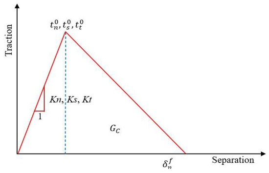
Figure 11.
Traction separation constitutive relationship.
Table 5.
Mechanical properties of cohesive interface element for epoxy layer in SB-E specimen [54].
4.3. Element Type, Interface, Boundary Condition, and Mesh
The RC slab (NSC), UHPFRC, CFRP strips, mechanical anchor system parts, steel plate support, and repair adhesive mortar were simulated using a 3D homogeneous stress eightـnode linear brick element (C3D8R) and reduced integration. In contrast, a two-node linear 3D truss solid element (T3D2) was employed to represent the reinforcing steel and CFRP rods [38]. To accurately represent the behavior of the epoxy adhesive layer with the NSC layer and UHPFRC jacket, a cohesive element (COH3D8) including the traction separation law was used. The initiation of damage to the epoxy adhesive was determined using a maximum insignificant stress standard reported by Smith et al. [55]. Figure 12 shows the layout and details of all the strengthening technique models. Various kinds of interaction in the FE study were identified, confirming that the responses of those components in the FE model accurately mirror the actual responses seen in the experimental investigation. Surface to surface interaction contact and hard-contact responses in the normal direction with a defined friction coefficient in the tangential orientation were used between the NC layer and UHPFRC jacket, expansion bolts and NC, expansion bolts and UHPFRC jacket, and anchor bolt and high-steel plate [22]. On the other hand, the interaction contact models between each of the (a) NSM adhesive mortar and NC layer, (b) steel plates and bottom face of the UHPFRC, and (c) CFRP strips and NC layer were assumed to be subject to a “tie constraint” [56]. The perfect bonding “embedded region” contact procedure represented the interface contact between the reinforcing steel and NC layer, CFRP bars and UHPFRC jacket, and CFRP rods and adhesive mortar. The friction coefficients between the NSC and UHPFRC layers and the mechanical expansion anchor bolt and NC-UHPFRC layers were determined to be 0.6 and 0.7, respectively [21,57]. In terms of boundary conditions, the support steel plates were modelled as a separate rigid/deformable element with restricted rotations and translations in three directions on the underside only in order to avoid convergence during the analysis. In addition, the top face of the support steel plate was modeled as being subject to surface-to-surface contact with NSC, as shown in Figure 12. The half-cyclic loads were evenly distributed across the entire upper face of the square steel plate. We used the dynamic explicit solver to analyze the cyclic loading. The half-cyclic loads were established using the amplitude cyclic frequency, as displayed in Figure 7. Three different FEM mesh sizes (20, 25, and 30) mm were analyzed for the RC slab elements to evaluate the accuracy of the numerical results. Comparisons were made between the findings for each FEM mesh size and the practical data, emphasizing the load–displacement curves. Based on these comparisons, a 20 mm mesh size was selected to provide a balance of accuracy in outcomes and computational competence. Therefore, all elements were specified as having a 20 mm sensitivity analysis mesh size for all strengthening techniques, as illustrated in Figure 12.

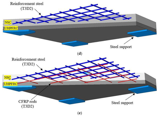
Figure 12.
Layout and details of all the strengthening technique models (dimensions are given in mm): (a) near-surface-mounted (NSM) CFRP rebars; (b) externally attached CFRP strips; (c) UHPFRC jacket with CFRP rods bonded via epoxy adhesive; and (d,e) externally attached jacket of UHPFRC without a mechanical anchor.
5. Discussion of Results
5.1. Experimental Slabs
Table 6 summarizes the outcomes for the tested slabs. It is worth noting here that the ductility indexes are based on the displacement values at the yielding and ultimate points and were calculated using Equation (13) [58]. Also, the energy absorption (E) ability of the slabs was calculated by specifying the deflection zone areas of the ultimate loads. Figure 13 shows the hysteretic half-cyclic load–deflection plots for the test slab specimens. Likewise, the crack patterns and failure behaviors observed in the slab specimens are shown in Figure 14.
μΔu = Δu/Δy
Table 6.
Summary results for tested slabs.
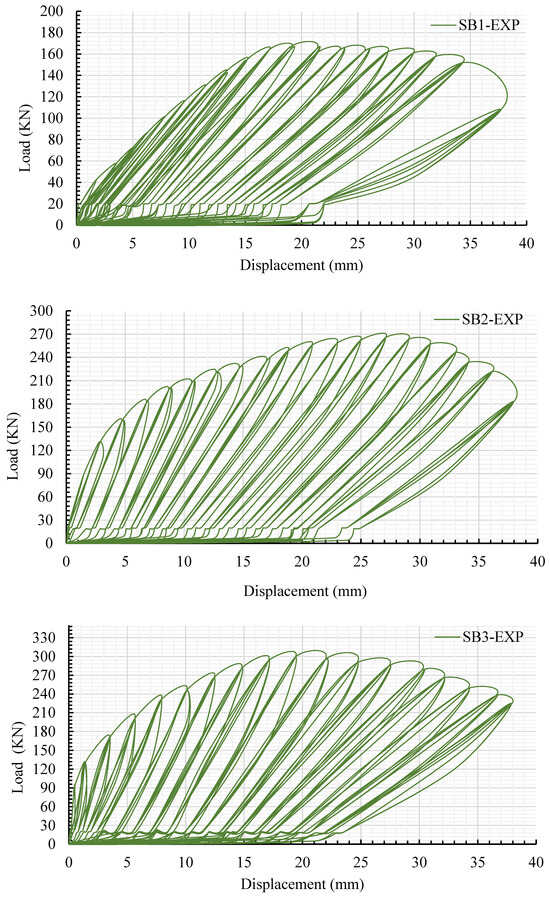
Figure 13.
Hysteretic half-cyclic load versus deflection of tested specimen slabs.
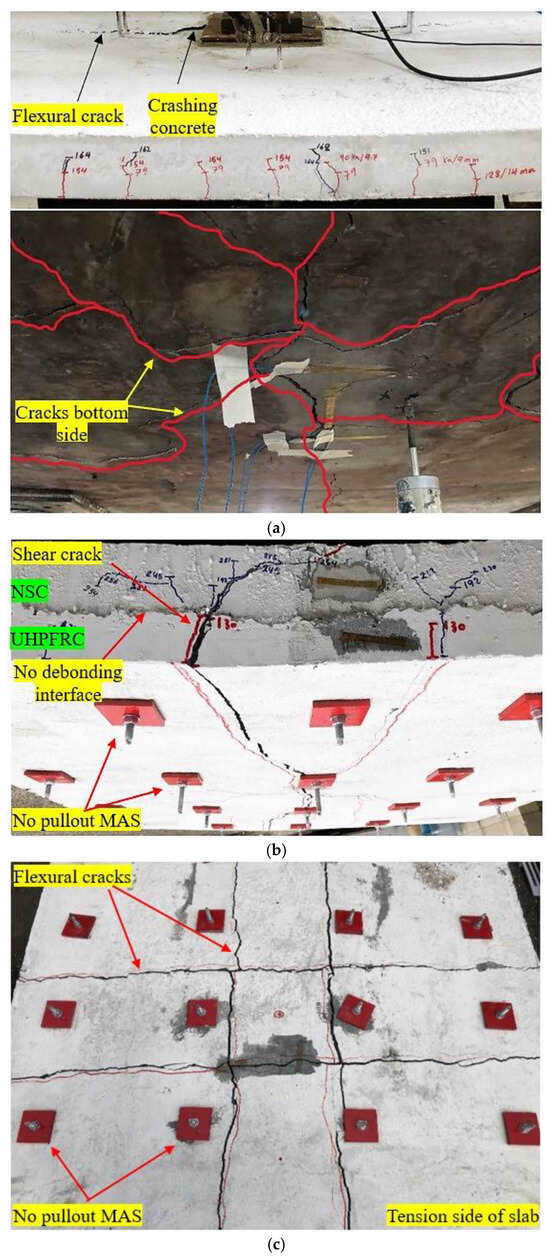
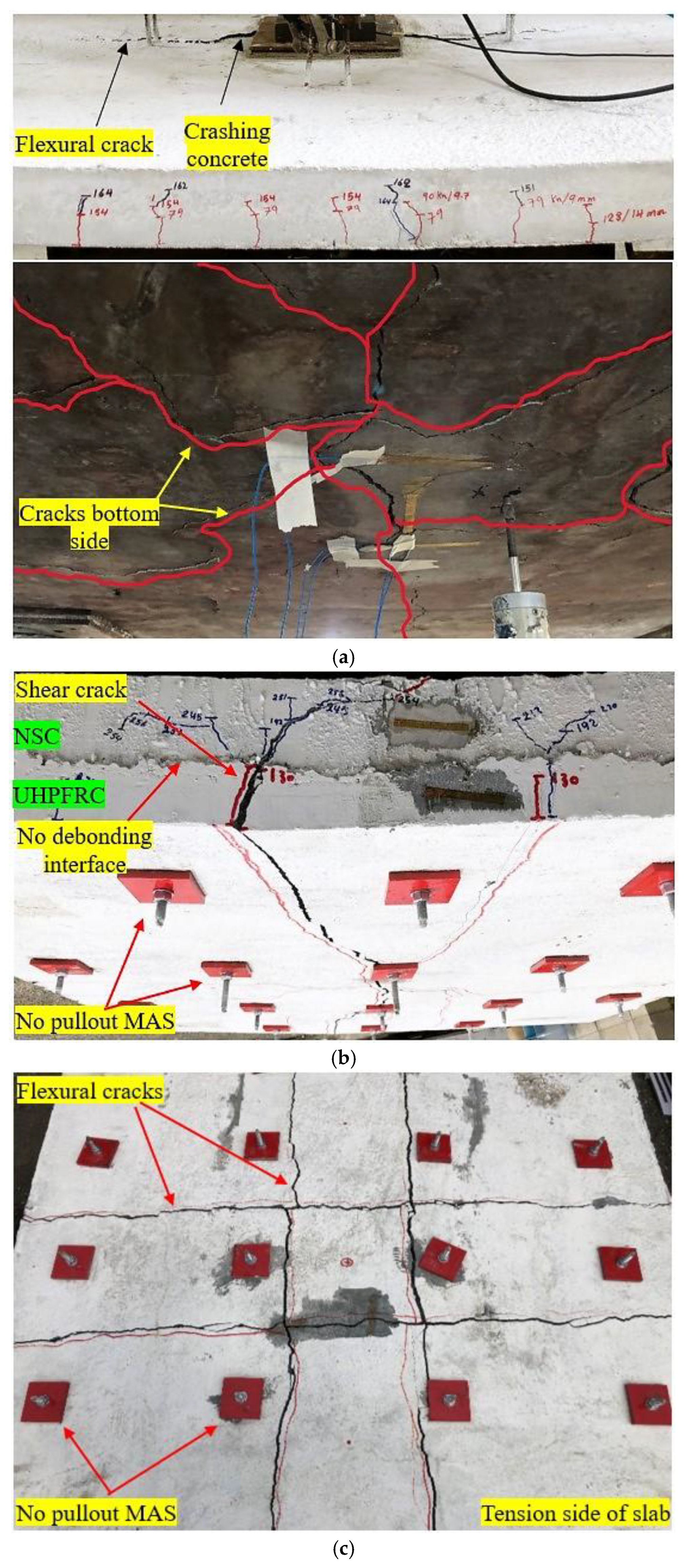
Figure 14.
Failure modes and crack patterns for tested slabs: (a) SB1; (b) SB2; and (c) SB3.
The control slab (SB1) had a flexural failure at an ultimate load of 164 kN, distinguished by the development of extensive vertical cracks at the midـspan point, followed by crushed concrete on the upper side, especially in the load area, as indicated in Figure 14. Remarkably, the cover of concrete exhibited spalling on the underside of the slab (the tension side). As shown in Figure 13 and Table 6, the load on SB1 increased linearly, and the first cracks occurred when the load reached 79 kN.
Significant macro-cracks on the undersurface of SB1 developed, and the rebar steel yielded due to the crushing of concrete at the loading area. On the other hand, Table 6 displays that the SB1 slab had a lower deflection ductility index and stiffness due to the crushing of concrete in the loading area and cracks propagating on all sides (Figure 14), unlike the strengthened slabs.
For the strengthened slab (SB2), shear failure was observed (Figure 14), in addition to crushing in the compression face of the slab, particularly in the load zone. This failure occurred when two shear cracks in opposite directions were generated in the middle of the span with a fracture of the UHPFRC jacket, as shown in Figure 14, and one crack reached the upper side of the NSC. The resistance to cracking was enhanced in the specimen that was reinforced with the newly suggested strengthening technique (SB2), resulting in an expansion in the linear stiffness range. As the load increased, SB2 demonstrated more stiffness until cracking occurred at 130 kN, as depicted in Table 6. The flexure stiffness and the load–deflection slope of SB2 were consistently greater than those of the un-strengthened slab (SB1) from the start to the end of testing. Therefore, the yielding strength and peak load of the refortified slab (SB2) improved from 152 kN and 164 kN to 244 kN and 264 kN, respectively, compared with SB1, as displayed in Table 6. Besides that, the stiffness and deflection ductility index of the refortified slab (SB2) were enhanced by 7% and 64%, respectively, compared to the SB1 specimen. These improvements are attributable to the UHPFRC’s high tensile characteristics, which improve crack control, reducing the width and propagation of cracks and permitting the slab to resist higher loads with more deflection before failure.
On the other hand, the SB3-strengthened slab demonstrated a diagonal flexural failure mechanism without signs of crushing or cracks observed in the upper face of the slab. Four regular cracks formed in opposite directions in the tension zone of the specimen slab and adjacent to the mechanical anchor systems, as shown in Figure 14. As shown in Table 6, SB3 demonstrated superior performance by resisting the increasing initial cracking load by almost twofold (156 kN) the value of the reference slab (SB1), which confirms the effectiveness of the newly suggested strengthening approach. In addition, as illustrated in Figure 14, incorporating CFRP bars inside the UHPFRC layer of the reinforced slab (SB3) led to a decrease in the number of cracks, with delayed crack initiation. The utilization and uniform distribution of mechanical anchor systems resulted in higher yielding and ultimate loads. The yielding load of the strengthened slab SB3 increased from 152 kN to 244 kN, constituting an increase of over 60%, as depicted in Table 6. In comparison with SB2, specimen SB3 demonstrated improved stiffness in all loading phases, and involving a CFRP mesh improved its load-bearing capacity by 13%. These results demonstrate the efficacy of CFRP rods in reducing deformation and improving the durability of slabs. Otherwise, the maximum loads of both retrofitted slabs SB3 and SB2 were higher than that of the SB1 slab. Table 6 demonstrates that SB2 increased the capacity of the slab by 61%, while SB3 enhanced the ultimate capacity by 82%. Besides that, the ductility and stiffness of SB3 improved by 85% and 46%, respectively, compared to the control slab. Table 6 shows that the strengthened slab (SB3) showed the most increased absorption capacity, namely, 8428 kN.mm, with the highest flexural value. Contrarily, SB2 demonstrated a reduction in the capacity of absorption by 436 kN.mm in comparison with the SB3 specimen. The substantial enhancement in the energy-absorbing capacity of SB3 reveals that embedding CFRP bars inside the UHPFRC layer enhanced energy excess performance. Compared to the control slab SB1, the fortified SB2 and SB3 displayed an average improvement in their capacity for energy absorption of 85% and 95%, respectively. Crucially, in the reinforced (SB2 and SB3) slabs, none of the mechanical anchor systems underwent any instances of being pulled out. Throughout the test stages, there was no debonding seen between the NSC and UHPFRC layers in both slabs SB2 and SB3, as displayed in Figure 14. Generally, the newly suggested method for strengthening the slabs demonstrated its considerable contributions to increasing cracking loads, ultimate loads, ductility, stiffness, and energy absorption and preventing premature debonding. This proves the reliability and effectiveness of the suggested strengthening method.
5.2. Verification of FE Models Using Experimental Results
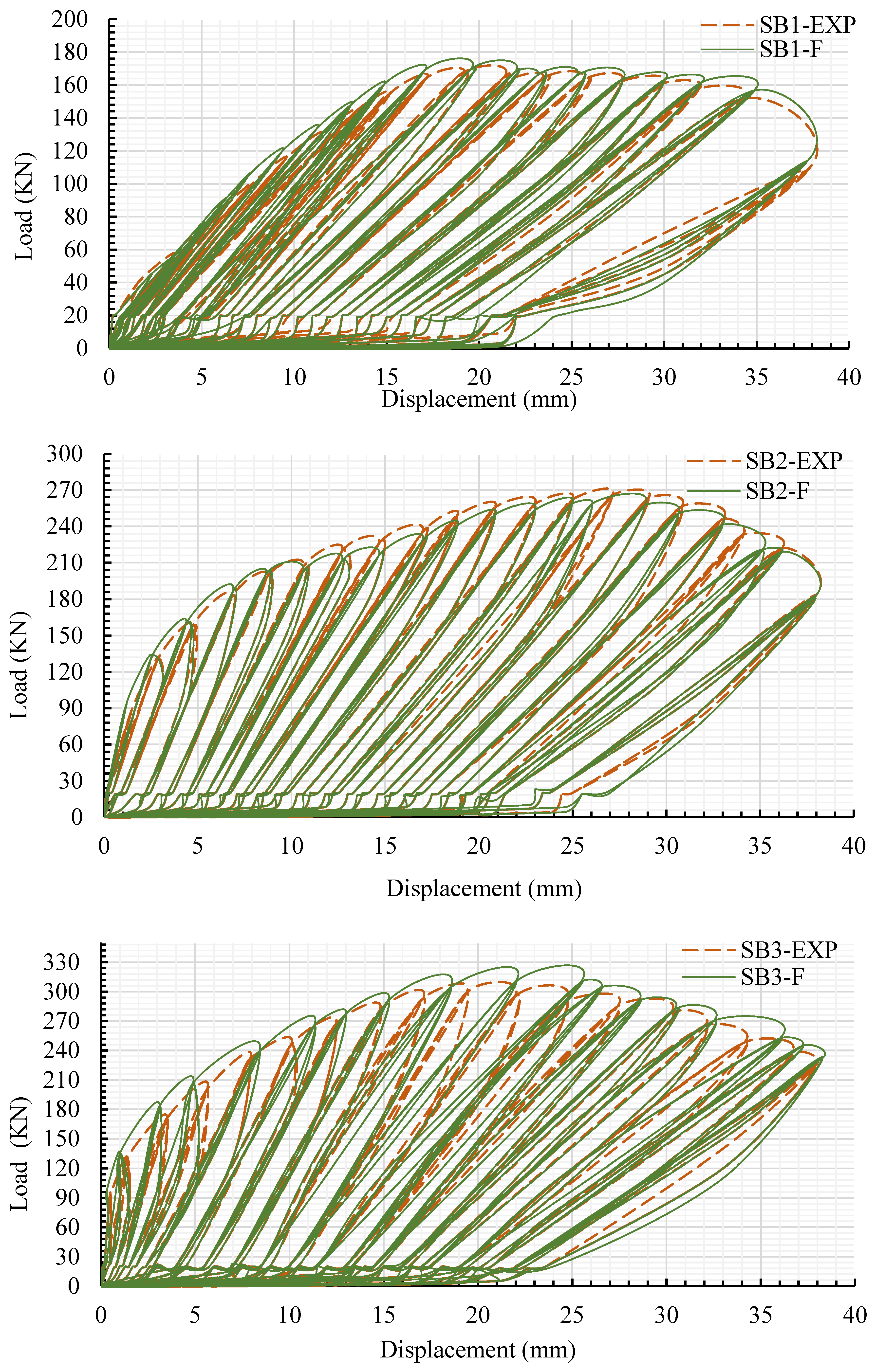
The FE specimens were developed based on the same geometric details and properties as the experimental slabs using the Abaqus software. Table 7 provides an overview and validates the FEM outcomes and the experimental study. Figure 15 illustrates the halfـcyclic load versus mid-span deflection in the experimental and FEM studies. Figure 15 and Table 7 display reasonable agreement between the FEM and experimental outcomes, demonstrating excellent accuracy. SB1-F demonstrated ductile behavior that nearly replicated the experimental findings, reaching an ultimate load of 169 kN, which closely matched the ultimate load observed in the experiment, as depicted in Table 7. Maximum load and displacement (deflection) improved by 3% and 8%, respectively, compared with those for SB1. These variations in outcomes can be ascribed to differences between the simulation boundary conditions and the real conditions. In contrast, the load–deflection slope for SB2-F displayed a slight increase compared to the slope for SB2 till the rebar steels started to yield, which happened at a load of approximately 200 kN, as depicted in Figure 15. Following the yielding of the reinforcing steel, the SB2-F slope decreased till the failure phase was reached. However, the SB2-F model demonstrated a loadـbearing capability of 260 kN and a deflection of 26 mm, as shown in Table 7. For the SB3-F model, the load–deflection slope slightly increased during all stages of simulation analysis compared to the slope for SB2, as displayed in Figure 15. Nevertheless, SB3-F indicated a maximum load of 312 kN and a corresponding deflection of 22 mm, as displayed in Table 7. The variations between SB3-F and SB3 (experimental slab) in terms of peak load and deflection were 3% and 4%, respectively. Figure 15 demonstrates that the stiffness of the SB3-F model is greater than that of SB3 (experimental slab). This difference may be due to the fact that the characteristics of the material used in the modelling do not accurately capture the realistic response of the composite slab.
Table 7.
Validation and comparison of the results from the FEM models with experimental outcomes.
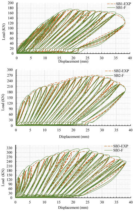
Figure 15.
Validation of FE half cyclic load versus deflection via experimental slabs.
Figure 16 validates the failure and crack patterns in the FEM and experimental specimens. The FEM simulation exhibited a significant level of concurrence with the experimental investigation concerning damage patterns and crack propagation, as demonstrated in Figure 16. In the case of the SB1-F control model, failure occurred when cracks emerged on the tension zone of the slab, followed by crashing of the concrete in the loading area, as shown in Figure 16. The undersurface of models SB2-F and SB3-F exhibited significant similarity with the experimental slabs in terms of the development of familiar cracks in opposite orientations in the center, as depicted in Figure 16.
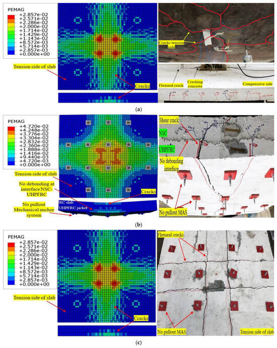
Figure 16.
Validation of FE failure mechanisms and crack patterns via experimental slabs: (a) control slab SB1; (b) strengthened slab SB2; and (c) strengthened slab SB3.
Furthermore, the plastic strain was more noticeable on the SB2-F and SB3-F models’ bottom middle surfaces, especially in the UHPFRC jacket, than at the corners. This indicates a greater tensile strain emerging in the middle areas of the models, as depicted in Figure 16. Notably, in the SB2F and SB3-F models, there was no occurrence of early debonding between the NC and UHPFRC layers, as observed for the experimental slabs. In addition, the mechanical anchor systems stayed securely in place without any pulling out, as shown in Figure 16. This indicates the outstanding effectiveness of the mechanical anchor systems and the interface contact strategy regarding the newly proposed strengthening system. Overall, the coefficients of variation (COV1) between the practical slabs and FEM models for ultimate load and mid-span deflection were 3.4% and 5.29%, respectively, as indicated in Table 7.
The validation procedure focused on numerous key aspects, including load–displacement response, failure modes, and crack patterns. To ensure the high reliability of the finite element model, the experimental outcomes were also used to validate the selected material constitutive laws and simulation input parameters. Based on the FEM outcomes in terms of initial elastic response, yield point, and peak behavior, the chosen material constitutive law models accurately captured the structural response. Numerical crack propagation and failure response were assessed using the principal strain contours and compared with experimental slabs. The closely resemblant types of failure and the propagation of cracks between the FEM and experimental models confirm the validity of the interaction models between all materials of the model and the bond behavior between them. In addition, with the application of a cyclic loading protocol and boundary conditions used in the experimental work, the FEM models effectively captured the hysteresis behavior, reflecting the practical trends. Generally, these verified outcomes confirm that the chosen material constitutive laws, conditions, and simulation parameters provide a precise explanation of the structural behavior of retrofitted RC slabs containing UHPFRC.
5.3. Results of the Comparison of Various Strengthening Methods
This section focusses on comparing the finite element (FE) models of different strengthening methods to evaluate the efficacy of the new strengthening system. This work involved using the near-surface-mounted (NSM) CFRP rebar method, the externally attached CFRP strips approach, and the epoxy adhesive method to bind the UHPFRC jacket reinforced with CFRP rods, as well as two models that are the same as the SB2 and SB3 experimental strengthened slab specimens except for the fact they do not have a mechanical anchor system. Details of the strengthening techniques are displayed in Figure 8. All strengthening techniques were modeled based on the experimental study in terms of geometric details and the properties of the materials. The outcomes for all the strengthening methods were compared with the SB2 and SB3 experimental slab findings.
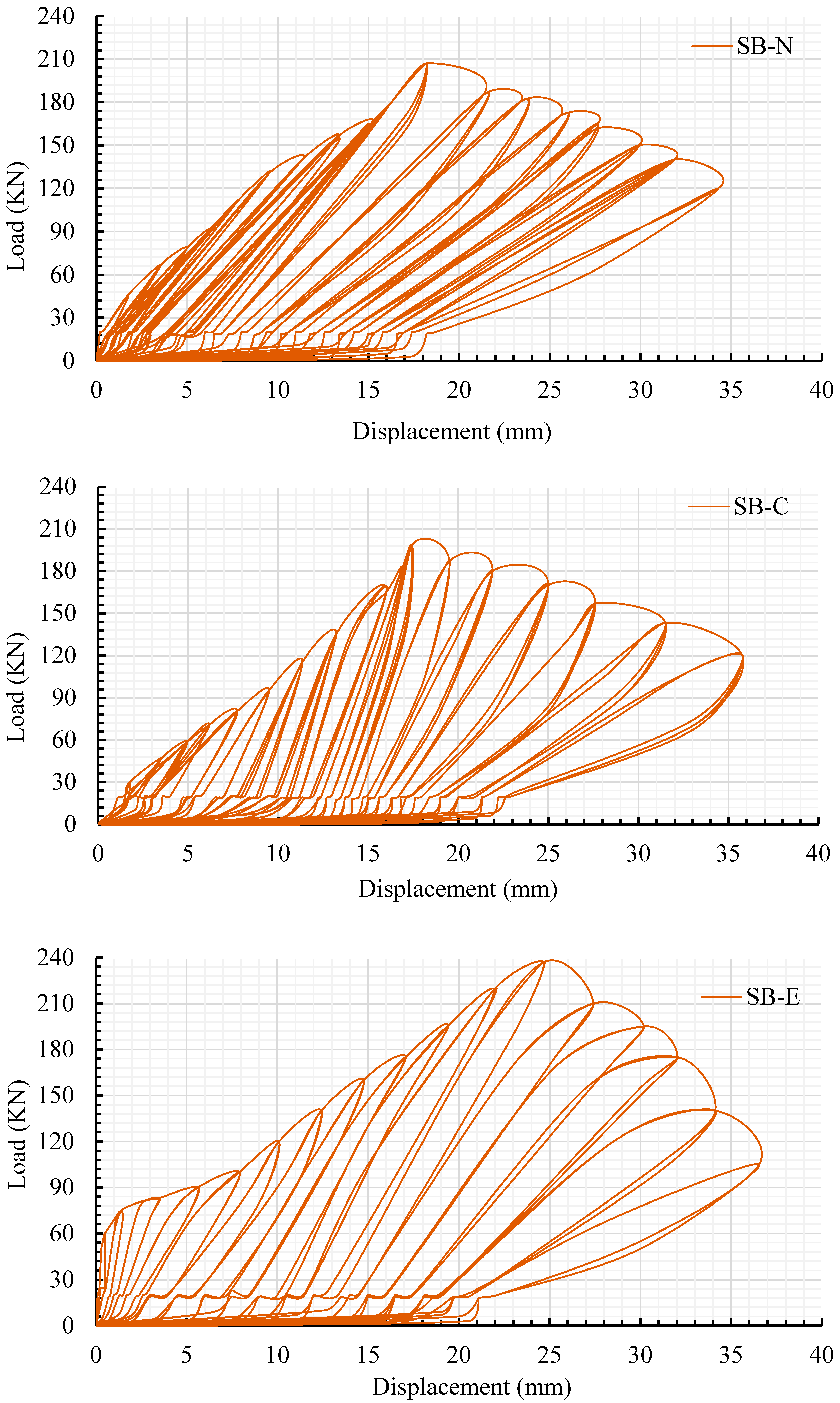
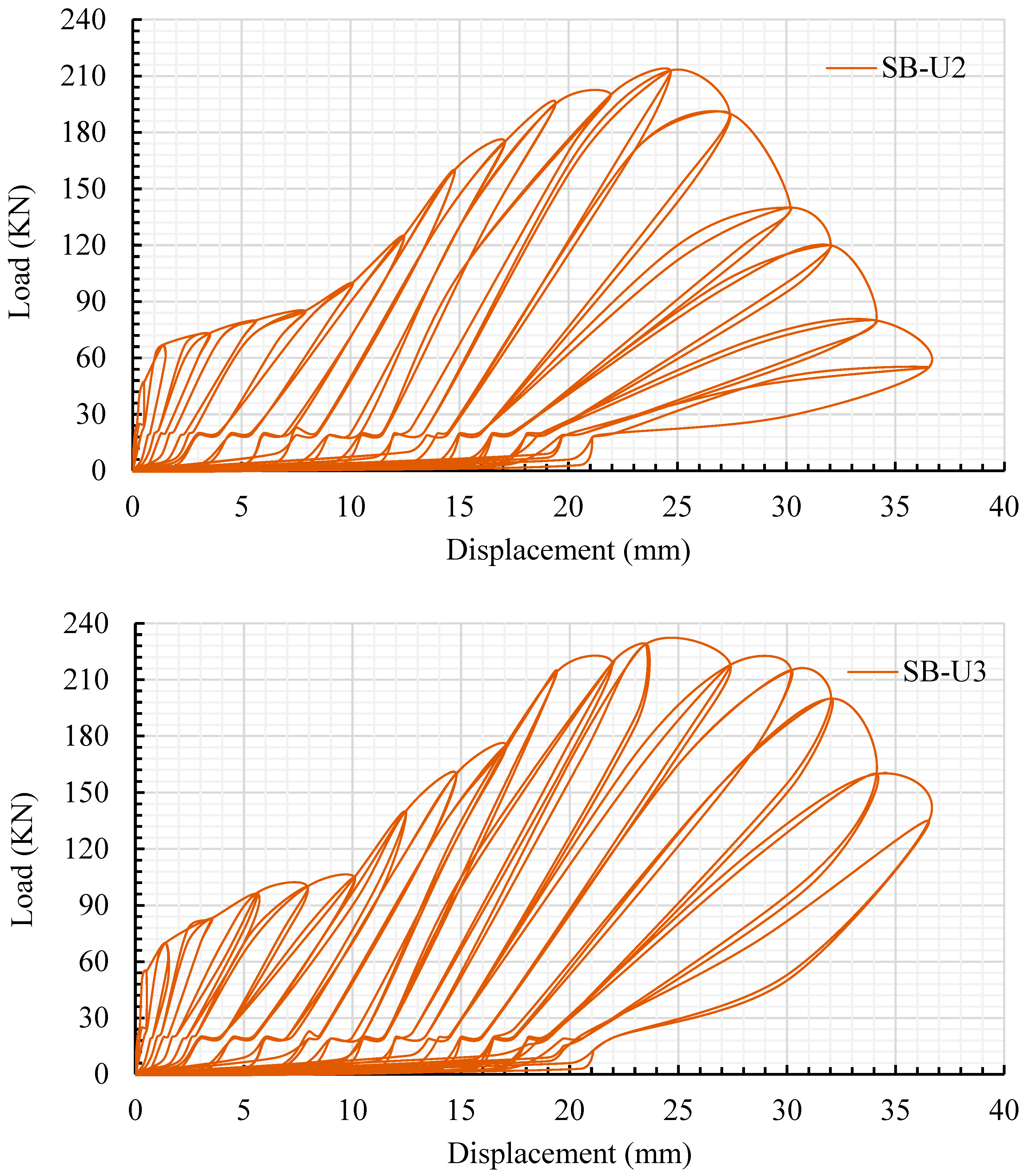
Table 7 compares the results of the strengthening techniques, as mentioned above, with the new system using the experimental results. Figure 17 illustrates the half-cyclic-load-versus-deflection curve, and Figure 18 exhibits the behavior of the failure and cracking patterns of the slabs modified using the traditional strengthening techniques.
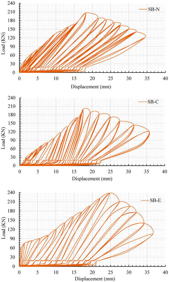
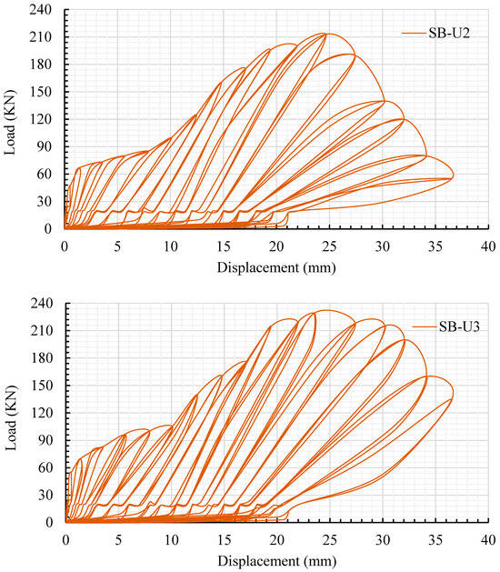
Figure 17.
Hysteretic halfـcyclic load versus deflection for slabs modified using the traditional strengthening techniques.

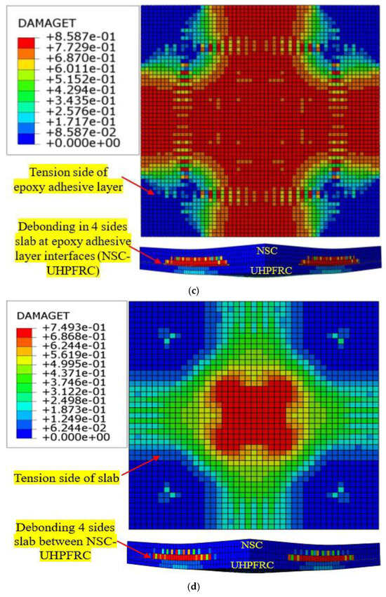
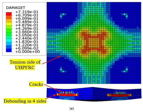
Figure 18.
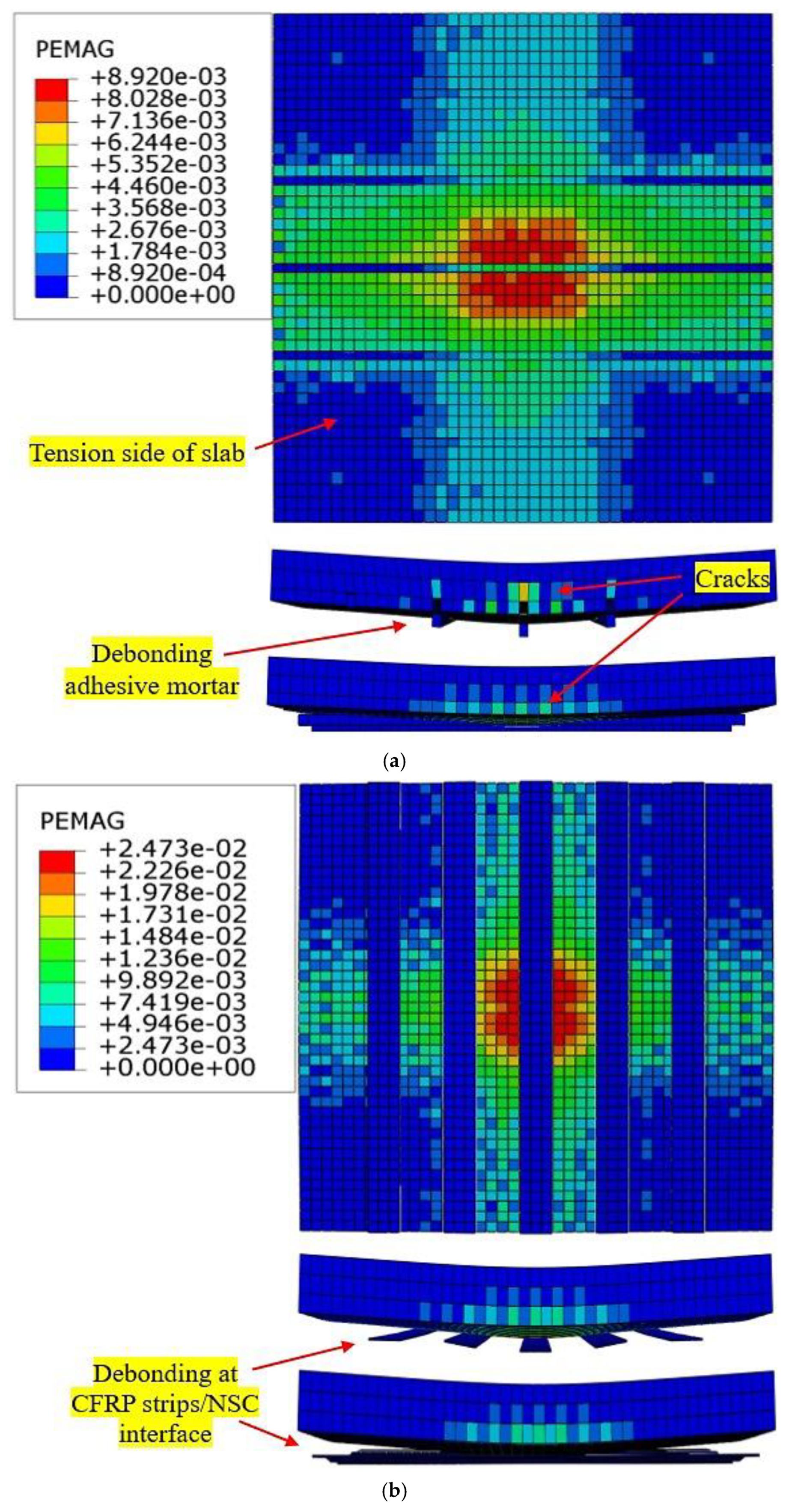
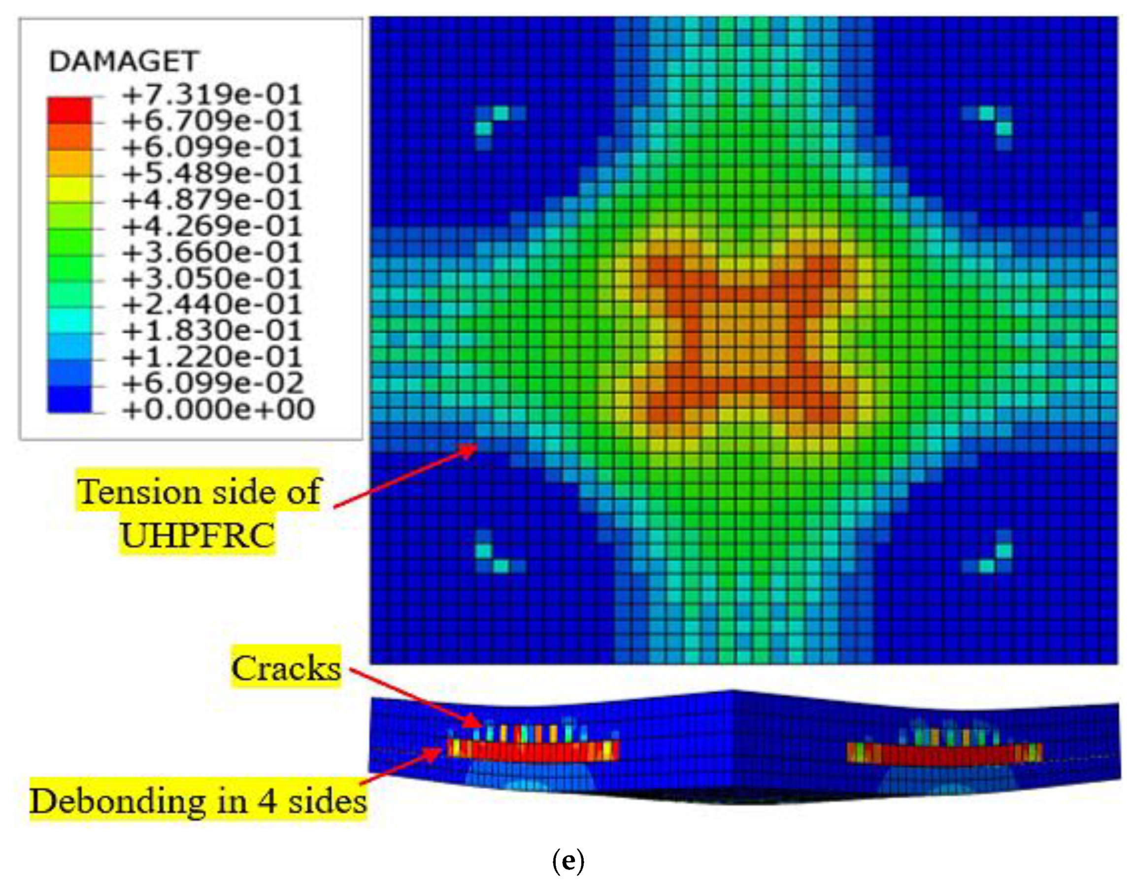
Cracks and failure patterns of slabs modified using the traditional strengthening techniques: (a) SB-N slab (NSM CFRP rod technique); (b) SB-C slab (externally attached CFRP strips technique); (c) SB-E slab (UHPFRC-jacket-with-CFRP-rods-and-epoxy-adhesive technique); (d) SB-U2 slab (UHPFRC jacket without a mechanical anchorage system); and (e) SB-U3 slab (UHPFRC jacket and CFRP rods without a mechanical anchorage system).
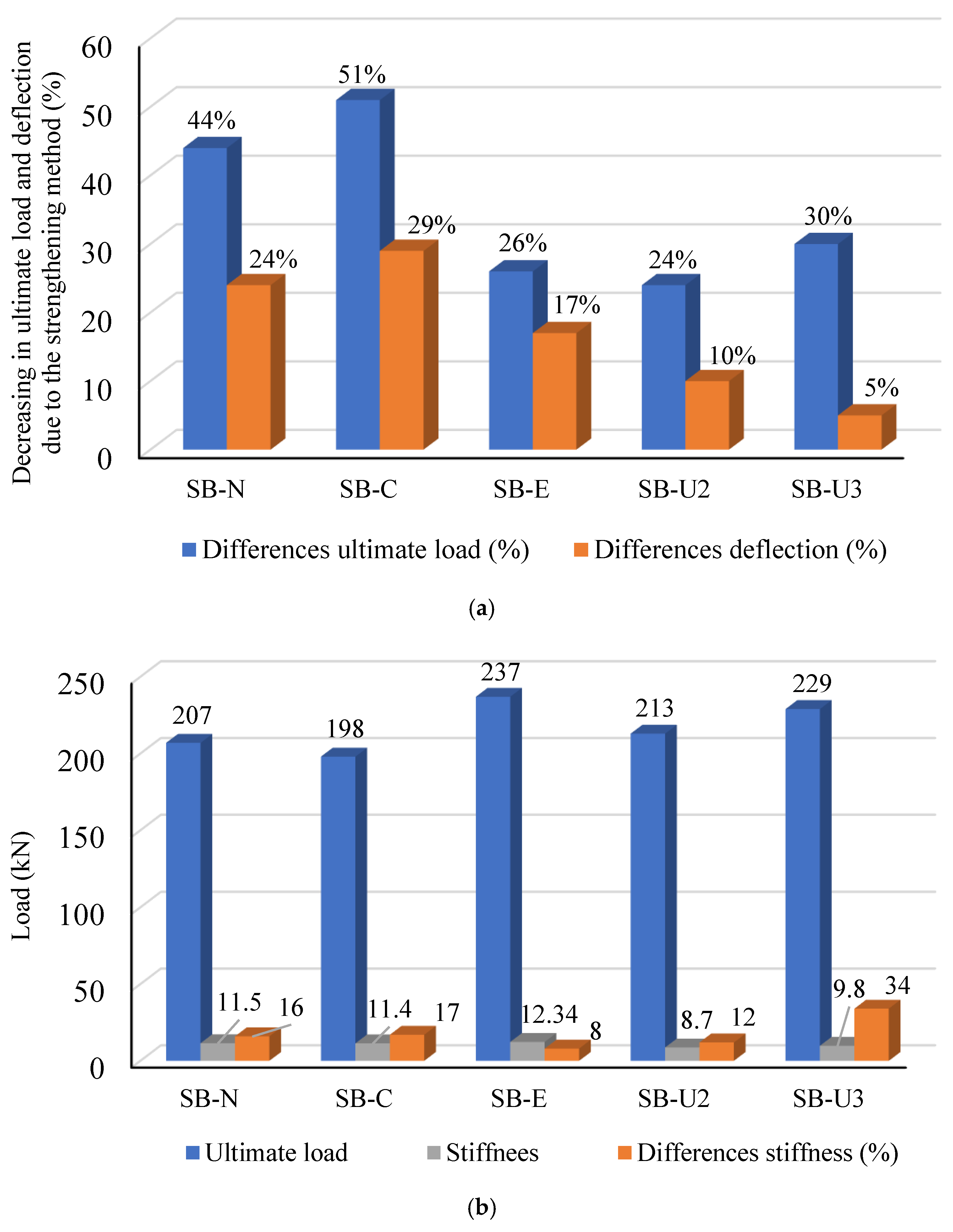
The SB-N, SB-C, and SB-E strengthened slabs exhibited a combination of flexural and premature debonding due to increased compressive stress at the interface contact surface between NSC and epoxy adhesive, as shown in Figure 18. For SB-N, premature debonding between the adhesive mortar and RC slab occurred in the center of the slab when the cyclic loads reached 0.75 times the ultimate load. Flexural cracks were observed on all sides of the slabs, as indicated in Figure 18. Compared to experimental slab SB3, the peak load of strengthened slabs SB-N, SB-C, and SB-E decreased by 91 kN, 100 kN, and 61 kN, respectively. Otherwise, the deflection at maximum load of the SB-N, SB-C, and SB-E strengthened slabs resulted in a decrement of 24%, 29%, and 17%, respectively, as shown in Figure 19. Additionally, the stiffness of the strengthened slabs modified using the near-surface-mounted (NSM) CFRP rebar approach, the externally attached CFRP strips approach, and the approach involving the use of the epoxy adhesive method to bond the UHPFRC jacket reinforced with CFRP rods decreased by 16%, 17%, and 8%, respectively, compared to that for experimental slab SB3 that was modified using the newly proposed strengthening system, as depicted in Figure 19.
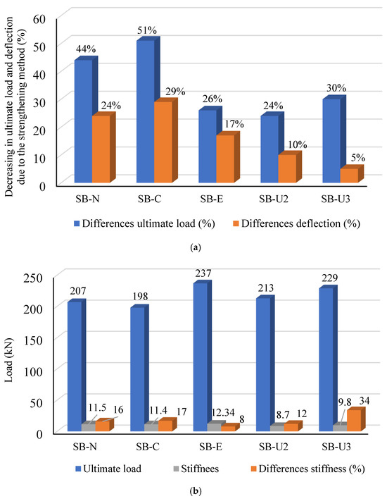
Figure 19.
Comparison of strengthening methods based on experimental slabs SB2 and SB3: (a) differences in ultimate load and deflection of slabs retrofitted with various techniques and (b) ultimate load and stiffness of slabs strengthened with various techniques.
In addition, two slab models, namely, SB-U2 and SB-U3, were developed to evaluate the influences of the mechanical anchor system on the performance of the retrofitted slabs. These models were designed in the same manner as the strengthened experimental slabs (SB2 and SB3) except for the fact that they did not have a mechanical bonding system. The impact of the mechanical anchor approach was assessed through three concepts: the increase in loads, stiffness, and the interaction contact surface between the NSC and UHPFRC layers. In comparison to experimental slabs SB2 and SB3, the peak loads of the SB-U2 and SB-U3 models decreased by 24% and 30%, respectively, as shown in Figure 19. Meanwhile, the stiffnesses of the SB-U2 and SB-U3 models were 8.7 kN/mm and 9.8 kN/mm, reflecting a reduction in the stiffness of the models by 12% and 34%, respectively, in comparison with the experimental retrofitted slabs. Furthermore, the coefficients of variation between the practical and SB-U2 and SB-U3 models’ outcomes in terms of the ultimate load were 11.4% and 15.8%, respectively, as demonstrated in Table 7. Figure 18d,e, reveal that the two slab models strengthened without a mechanical system displayed notable high-strain behavior concentrated in the center of the slabs and the interface between NSC-UHPFRC layers. Besides that, the SB-U2 and SB-U3 models experienced failure due to debonding between the NSC-UHPFRC layers on all four sides of the specimens, as depicted in Figure 18d,e. Therefore, it can be concluded that the impact of the absence of a mechanical anchor system in these two models reduced the peak loads and the rigidity of the slabs and increased the probability of occurrence of debonding failure. According to the results discussed above, the newly proposed strengthening method is more effective and efficient than the other strengthening systems examined in this study.
6. Analytical Model of Slabs
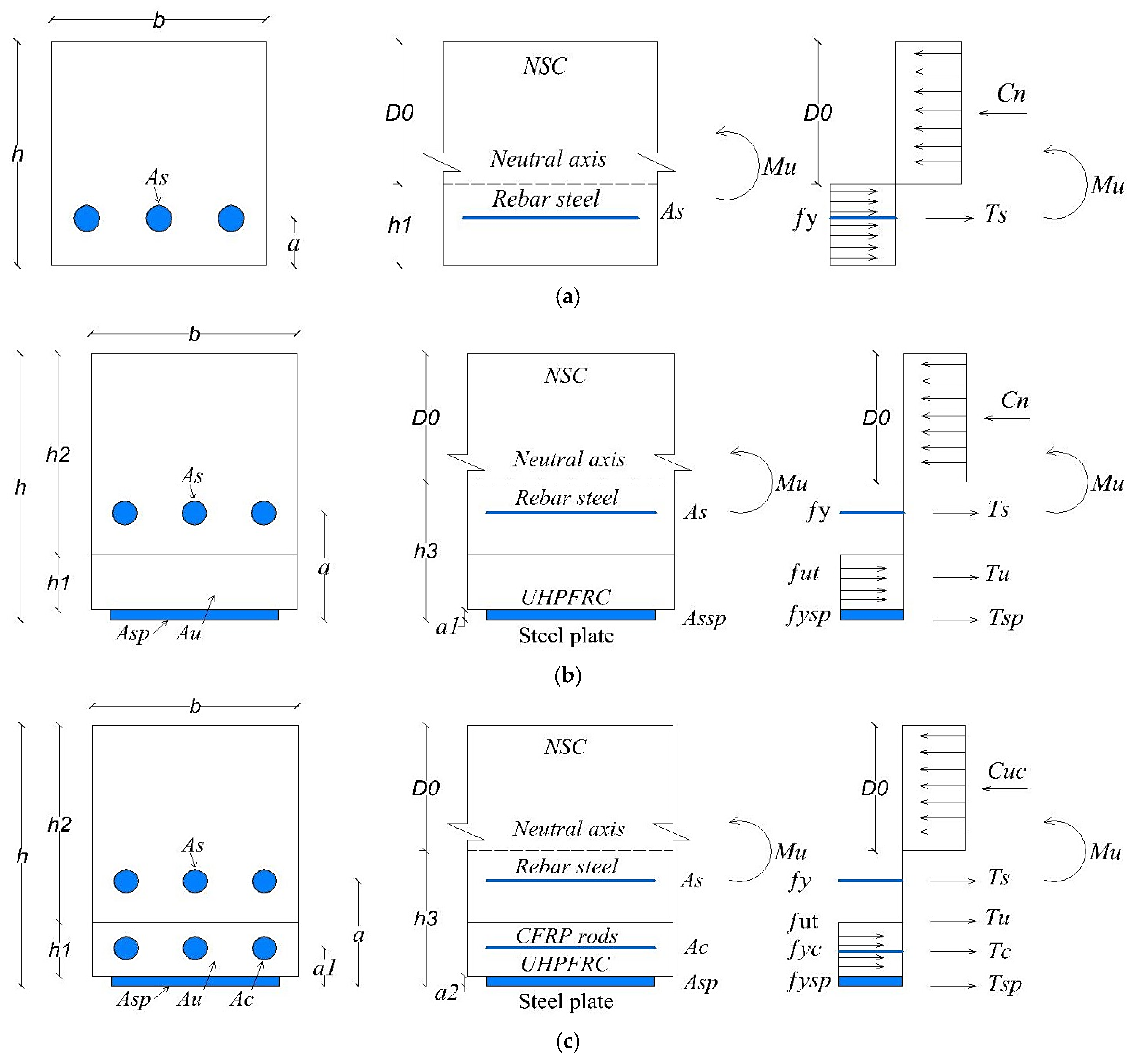
Analytical mechanistic models were employed to determine the flexural moment capacity of the RC slabs that were strengthened using various techniques. In this investigation, we utilized internal stresses derived from the basic plastic theory for composite materials to estimate internal forces. Flexural moments were calculated through the analysis of internal forces within the RC slabs at a certain cross-section in an equilibrium condition. Figure 20 depicts the schemes of all the analytical models of the RC slabs. According to the schemes of the analytical models, the reinforcing steel, CFRP bars, CFRP strips, and steel plates were supposed to be under tension, as depicted in Figure 20. Besides that, the epoxy adhesive mortar was neglected in the analysis. A Whitney stress block, which is a rectangular distribution of stress with comparable properties, was utilized to model the compressive behavior of NC in accordance with the specifications outlined in Section 10.2.7 of the ACI Code [59]. The value of [], representing the height of the NC at the compression region, is calculated based on equilibrium axial force [59], as described in Equations (14)–(19). The ultimate moment capacities of the slabs were calculated by analyzing the interior forces acting on the neutral axis. Therefore, the flexural moment capability [Mu] for all methods of strengthening a slab can be expressed using Equations (20)–(25).
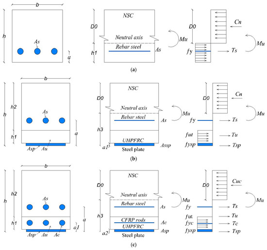
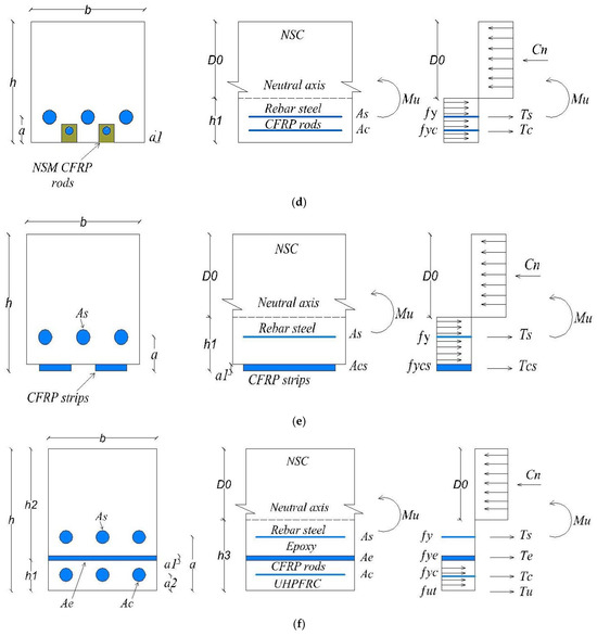
Figure 20.
Scheme of analytical models for RC slabs: (a) control slab SB1; (b) strengthened slab SB2; (c) strengthened slab SB3; (d) strengthened slab SB-N; (e) strengthened slab SB-C; and (f) strengthened slab SB-E.
The height of the NC at the compression region for all models can be obtained through the following equations [59]:
Therefore, the flexural moment capability [Mu] values can be derived from the subsequent equations [59]:
fc and fut represent the compressive strength of NSC and UHPFRC, respectively; fy, fyc, fysp, and fye represent the yield strengths of reinforcing steel, CFRP rods, steel plates, and epoxy adhesive, respectively; As and Ac represent the cross-section areas of the rebar steel bars and CFRP bars, respectively; Ts, Tu, Tc, Te, Tcs, and Tsp (in Figure 20) represent tensile resultant forces in reinforcing steel, UHPFRC, CFRP rods, adhesive mortar, CFRP strips, and steel plates, respectively; Cn (in Figure 20) represents the compressive resultant forces on NSC.
Validation of Results for the Analytical Models
The findings obtained from the analytical model strategy were compared to the practical and FEM results, as depicted in Table 8. Analytical design equations from other work [26,56] from the existing literature were applied to validate the ability of these formulas to determine the maximum moment capacity (Mu) of RC members, as shown in Table 8. The findings of the analytical design models demonstrated a reasonable agreement corresponding to the experimental and finite element (FEM) results. However, as revealed in Table 6, the variations (COV) between the practical-analytical and finite element analytical models were 4.3% and 6%, respectively. These outcomes demonstrate that the analytical study approach can be utilized to forecast the flexure moment capability of RC members refortified by employing different techniques.
Table 8.
Validation of the analytical models.
7. Conclusions
In this research, we examined the experimental, numerical, and analytical aspects of improving RC slabs by mechanically anchoring an external UHPFRC jacket system to the tension faces of the slabs. Therefore, an experimental test was performed on the slabs by applying incremental repeating loads (half-cyclic loads), and FEM and analytical outcomes were validated using the experimental outcomes. In addition, a comprehensive comparison was made between the three different strengthening techniques and the newly proposed strengthening system, and the following conclusions can be drawn:
- The suggested retrofitting system substantially improved resistance to initial cracks and delayed the development of flexural cracks in the slabs.
- The retrofitted reinforced concrete slabs exhibited an 82% higher initial cracking load compared to the reference slab.
- The maximum load capacity of the retrofitted RC slabs increased by 61% and 82%, respectively, and the stiffness also improved by 7% and 46%.
- The proposed strengthening technique effectively prevented early debonding, as no debonding occurred between the NSC and UHPFRC layers throughout all the phases of testing.
- The mechanical anchor systems stayed firmly intact within the slabs up to the failure phase, indicating the effectiveness and reliability of the proposed retrofitting approach.
- The finite element (FE) outcomes for both the unstrengthened and strengthened slabs exhibited a high degree of alignment with the experimental findings.
- The newly proposed strengthening method proved to be more efficient and effective in improving slab performance compared to traditional techniques.
- The stiffness of the strengthened slabs that were modified using traditional methods (near-surface-mounted (NSM) CFRP rebar approach, externally attached CFRP strips approach, and the use of an epoxy adhesive method to bond the UHPFRC jacket) decreased by 16%, 17%, and 8%, respectively, compared to the SB3 experimental slab.
- The analytical model approach yielded good estimates for forecasting the maximum moment capacity of RC -members reinforced by employing different techniques.
- It is recommended to carry out further studies on the application of the newly proposed technique to other reinforced concrete members, such as columns or beams, because it significantly enhanced the strength of the RC slabs and prevented premature debonding.
Author Contributions
Conceptualization, F.H.S. and F.H.; methodology, F.H.S. and F.H.; software, F.H.S.; formal analysis, F.H.S.; investigation, F.H.S.; resources, F.H.; data curation, F.H.S.; writing—original draft, F.H.S.; writing—review and editing, F.H.; visualization, F.H.S.; supervision, F.H.; project administration, F.H.; funding acquisition, F.H. All authors have read and agreed to the published version of the manuscript.
Funding
This research received no external funding.
Institutional Review Board Statement
Not applicable.
Informed Consent Statement
Not applicable.
Data Availability Statement
All data generated or analyzed during this study are included in this published article.
Conflicts of Interest
The authors declare no conflicts of interest.
References
- Prem, P.R.; Murthy, A.R. Acoustic emission and flexural behaviour of RC beams strengthened with UHPC overlay. Constr. Build. Mater. 2016, 123, 481–492. [Google Scholar] [CrossRef]
- Hassan, F.; Hejazi, F.; Saifulnaz, R.; Rashid, M. Strengthening of reinforced concrete slabs using carbon fiber reinforced polymers rods and concrete jacket with a mechanical anchorage system. Constr. Build. Mater. 2024, 440, 137464. [Google Scholar] [CrossRef]
- Brühwiler, E. Rehabilitation of concrete bridges using Ultra-High Performance Fibre Reinforced Concrete (UHPFRC). In Proceedings of the 3rd International Symposium on Life-Cycle Civil Engineering, Vienna, Austria, 3–6 October 2012; Volume 1, pp. 1934–1941. Available online: https://infoscience.epfl.ch/handle/20.500.14299/86194 (accessed on 12 February 2022).
- Le Hoang, A.; Fehling, E. Influence of steel fiber content and aspect ratio on the uniaxial tensile and compressive behavior of ultra high performance concrete. Constr. Build. Mater. 2017, 153, 790–806. [Google Scholar] [CrossRef]
- Tayeh, B.A.; Bakar, B.H.A.; Johari, M.A.M.; Voo, Y.L. Mechanical and permeability properties of the interface between normal concrete substrate and ultra high performance fiber concrete overlay. Constr. Build. Mater. 2012, 36, 538–548. [Google Scholar] [CrossRef]
- Brühwiler, E.; Denarié, E. Rehabilitation and Strengthening of Concrete Structures Using Ultra-High Performance Fibre Reinforced Concrete. Struct. Eng. Int. 2013, 23, 450–457. [Google Scholar] [CrossRef]
- Wu, Z.; Shi, C.; Khayat, K.H. Investigation of mechanical properties and shrinkage of ultra-high performance concrete: Influence of steel fiber content and shape. Compos. Part B Eng. 2019, 174, 107021. [Google Scholar] [CrossRef]
- Noshiravani, T.; Brühwiler, E. Rotation capacity and stress redistribution ability of R-UHPFRC-RC composite continuous beams: An experimental investigation. Mater. Struct. Constr. 2013, 46, 2013–2028. [Google Scholar] [CrossRef]
- Habel, K.; Gauvreau, P. Response of ultra-high performance fiber reinforced concrete (UHPFRC) to impact and static loading. Cem. Concr. Compos. 2008, 30, 938–946. [Google Scholar] [CrossRef]
- Chun, B.; Yoo, D.Y. Hybrid effect of macro and micro steel fibers on the pullout and tensile behaviors of ultra-high-performance concrete. Compos. Part B Eng. 2019, 162, 344–360. [Google Scholar] [CrossRef]
- Liu, J.; Han, F.; Cui, G.; Zhang, Q.; Lv, J.; Zhang, L.; Yang, Z. Combined effect of coarse aggregate and fiber on tensile behavior of ultra-high performance concrete. Constr. Build. Mater. 2016, 121, 310–318. [Google Scholar] [CrossRef]
- Banerji, S.; Kodur, V.; Solhmirzaei, R. Experimental behavior of ultra high performance fiber reinforced concrete beams under fire conditions. Eng. Struct. 2020, 208, 110316. [Google Scholar] [CrossRef]
- Murthy, A.R.; Karihaloo, B.L.; Rani, P.V.; Priya, D.S. Fatigue behaviour of damaged RC beams strengthened with ultra high performance fibre reinforced concrete. Int. J. Fatigue 2018, 116, 659–668. [Google Scholar] [CrossRef]
- El-Mandouh, M.A.; Elsamak, G.; Rageh, B.O.; Hamoda, A.; Abdelazeem, F. Experimental and numerical investigation of one-way reinforced concrete slabs using various strengthening systems. Case Stud. Constr. Mater. 2023, 18, e01691. [Google Scholar] [CrossRef]
- Nadir, W.; Kadhimi, M.M.A.; Jawdhari, A.; Fam, A.; Majdi, A. RC beams strengthened in shear with FRP-Reinforced UHPC overlay: An experimental and numerical study. Structures 2023, 53, 693–715. [Google Scholar] [CrossRef]
- Wang, H.; Zhou, Z.; Zhang, Z.; Zou, Y.; Jiang, J.; Zeng, X. Experimental and numerical studies on shear behavior of prefabricated bridge deck slabs with compact UHPC wet joint. Case Stud. Constr. Mater. 2023, 19, e02362. [Google Scholar] [CrossRef]
- Su, Y.L.; Wu, C.; Shang, J.Q.; Zhang, P.; Sheikh, S.A. Experimental and numerical simulation research on the flexural performance of beams reinforced with GFRP bars and three-sides UHPC layer. Structures 2024, 59, 105746. [Google Scholar] [CrossRef]
- Shan, Y.; Gong, Y.; Wang, Y.; Zhou, Q.; Li, X.; Ding, F.; Kuang, Y. Flexural behavior of ultra-high performance concrete (UHPC) shaped thin-plate ribbed staircases: An experimental and numerical study. Mater. Struct. Constr. 2024, 57, 18. [Google Scholar] [CrossRef]
- Safdar, M.; Matsumoto, T.; Kakuma, K. Flexural behavior of reinforced concrete beams repaired with ultra-high performance fiber reinforced concrete (UHPFRC). Compos. Struct. 2016, 157, 448–460. [Google Scholar] [CrossRef]
- Paschalis, S.A.; Lampropoulos, A.P.; Tsioulou, O. Experimental and numerical study of the performance of ultra high performance fiber reinforced concrete for the flexural strengthening of full scale reinforced concrete members. Constr. Build. Mater. 2018, 186, 351–366. [Google Scholar] [CrossRef]
- Murthy, A.R.; Karihaloo, B.L.; Priya, D.S. Flexural behavior of RC beams retrofitted with ultra-high strength concrete. Constr. Build. Mater. 2018, 175, 815–824. [Google Scholar] [CrossRef]
- Ahmed, S.; Mohamed, E.Y.; Mohamed, H.A.; Emara, M. Experimental and numerical investigation of flexural behavior of RC beams retrofitted with reinforced UHPFRC layer in tension surface. Structures 2023, 49, 106–123. [Google Scholar] [CrossRef]
- Yang, J.; Yu, J.; Zhang, Z.; Zou, Y.; Chen, R.; Zhou, J.; Li, B. Flexural behavior of 15-year-old full-scale hollow slab beams strengthened with fiber-reinforced composites. Case Stud. Constr. Mater. 2023, 19, e02545. [Google Scholar] [CrossRef]
- Zhang, Y.; Wang, H.; Qin, Y.; Huang, S.; Fan, W. Experimental and analytical studies on the flexural behavior of steel plate-UHPC composite strengthened RC beams. Eng. Struct. 2023, 283, 115834. [Google Scholar] [CrossRef]
- Yoo, D.Y.; Banthia, N.; Kim, S.W.; Yoon, Y.S. Response of ultra-high-performance fiber-reinforced concrete beams with continuous steel reinforcement subjected to low-velocity impact loading. Compos. Struct. 2015, 126, 233–245. [Google Scholar] [CrossRef]
- Lampropoulos, A.P.; Paschalis, S.A.; Tsioulou, O.T.; Dritsos, S.E. Strengthening of reinforced concrete beams using ultra high performance fibre reinforced concrete (UHPFRC). Eng. Struct. 2016, 106, 370–384. [Google Scholar] [CrossRef]
- Hong, S.G.; Lim, W.Y. Strengthening of shear-dominant reinforced concrete beams with ultra-high-performance concrete jacketing. Constr. Build. Mater. 2023, 365, 130043. [Google Scholar] [CrossRef]
- Yin, H.; Teo, W.; Shirai, K. Experimental investigation on the behaviour of reinforced concrete slabs strengthened with ultra-high performance concrete. Constr. Build. Mater. 2017, 155, 463–474. [Google Scholar] [CrossRef]
- Paschalis, S.A.; Lampropoulos, A.P. Developments in the use of Ultra High Performance Fiber Reinforced Concrete as strengthening material. Eng. Struct. 2021, 233, 111914. [Google Scholar] [CrossRef]
- Said, A.; Elsayed, M.; El-Azim, A.A.; Althoey, F.; Tayeh, B.A. Using ultra-high performance fiber reinforced concrete in improvement shear strength of reinforced concrete beams. Case Stud. Constr. Mater. 2022, 16, e01009. [Google Scholar] [CrossRef]
- Qsymah, A.; Ayasrah, M. Finite Element Analysis of Two-Way Reinforced Concrete Slabs Strengthened with FRP Under Flexural Loading. Buildings 2024, 14, 3389. [Google Scholar] [CrossRef]
- Pedram, Z.; Xiong, Y.; Xin, J.; Amir, M. Punching Shear Enhancement of Flat Slabs with Partial Use of Ultrahigh-Performance Concrete. J. Mater. Civ. Eng. 2015, 27, 4014255. [Google Scholar] [CrossRef]
- ASTM Standard A29/A29M −12; Standard Specification for General Requirements for Steel Bars, Carbon and Alloy, Hot-Wrought. ASTM International: West Conshohocken, PA, USA, 2013; Volume 1, pp. 1–16.
- PRODUCT DATA SHEET. Sika ® CarboDur ® BC 8. BUILDING TRUST. 2023. Available online: https://gbr.sika.com/dam/dms/gb01/j/sika-carbodur-bc8.pdf (accessed on 11 March 2023).
- Datasheet, T. Hilti HST3 Expansion Anchor. Hilti. Available online: https://www.hilti.com (accessed on 11 March 2023).
- Pan, B.; Liu, F.; Zhuge, Y.; Zeng, J.J.; Liao, J.J. ECCs/UHPFRCCs with and without FRP reinforcement for structural strengthening/repairing: A state-of-the-art review. Constr. Build. Mater. 2022, 316, 125824. [Google Scholar] [CrossRef]
- PRODUCT DATA SHEET. Sikadur®-732. BUILDING TRUST. 2020. Available online: https://sgp.sika.com/dam/dms/sg01/d/sikadur_-732.pdf (accessed on 11 March 2023).
- Abaqus theory manual. Abaqus 6.13 Documents; no. Dassault Systemes Simulia Corp.: Providence, RI, USA, 2014. [Google Scholar]
- Khalaf, M.R.; Al-Ahmed, A.H.A.; Allawi, A.A.; El-Zohairy, A. Strengthening of continuous reinforced concrete deep beams with large openings using cfrp strips. Materials 2021, 14, 3119. [Google Scholar] [CrossRef]
- Al-Rousan, R.Z. Integration of CFRP strips as an internal shear reinforcement in reinforced concrete beams exposed to elevated temperature. Case Stud. Constr. Mater. 2021, 14, e00508. [Google Scholar] [CrossRef]
- Su, M.; Gong, S.; Liu, Y.; Peng, H. Flexural behavior of RC beams strengthened with fully or partially prestressed near-surface mounted FRP strips: An experimental investigation. Eng. Struct. 2022, 262, 114345. [Google Scholar] [CrossRef]
- Hosen, M.A.; Jumaat, M.Z.; Alengaram, U.J.; Sulong, N.H.R. CFRP strips for enhancing flexural performance of RC beams by SNSM strengthening technique. Constr. Build. Mater. 2018, 165, 28–44. [Google Scholar] [CrossRef]
- Aules, W.; Saeed, Y.M.; Rad, F.N. A novel anchorage system for strengthening slender RC columns with externally bonded CFRP composite sheets. Constr. Build. Mater. 2020, 245, 118423. [Google Scholar] [CrossRef]
- Barris, C.; Sala, P.; Gómez, J.; Torres, L. Flexural behaviour of FRP reinforced concrete beams strengthened with NSM CFRP strips. Compos. Struct. 2020, 241, 112059. [Google Scholar] [CrossRef]
- Karayannis, C.; Golias, E. An Innovative Technique for the Strengthening of RC Columns and Their Connections with Beams Using C-FRP ROPES. Appl. Sci. 2024, 14, 8395. [Google Scholar] [CrossRef]
- Saeed, Y.M.; Aules, W.A.; Rad, F.N.; Raad, A.M. Tensile behavior of FRP anchors made from CFRP ropes epoxy-bonded to uncracked concrete for flexural strengthening of RC columns. Case Stud. Constr. Mater. 2020, 13, e00435. [Google Scholar] [CrossRef]
- 440.2R-17; Guide for the Design and Construction of Externally Bonded FRP Systems for Strengthening Concrete Structures. ACI: Farmington Hills, MI, USA, 2017.
- ACI 318-19; Building Code Requirements for Structural Concrete (Reapproved 2022). ACI: Farmington Hills, MI, USA, 2019.
- GB 50010; National Standard of the People’s Republic of China—Code for Design of Concrete Structures. Construction: Beijing, China, 2002; pp. 64–73.
- Jia, L.; Fang, Z.; Huang, Z.; Pilakoutas, K.; Wang, Q.; Tan, X. Flexural behavior of uhpc beams prestressed with external cfrp tendons. Appl. Sci. 2021, 11, 9189. [Google Scholar] [CrossRef]
- Birtel, V.; Mark, P. Parameterised Finite Element Modelling of RC Beam Shear Failure. In Proceedings of the ABAQUS Users’ Conference, Cambridge, MA, USA, 23–25 May 2006; pp. 95–108. [Google Scholar]
- Obaidat, Y.T.; Heyden, S.; Dahlblom, O. The effect of CFRP and CFRP/concrete interface models when modelling retrofitted RC beams with FEM. Compos. Struct. 2010, 92, 1391–1398. [Google Scholar] [CrossRef]
- Zidani, M.B.; Belakhdar, K.; Tounsi, A.; Bedia, E.A.A. Finite element analysis of initially damaged beams repaired with FRP plates. Compos. Struct. 2015, 134, 429–439. [Google Scholar] [CrossRef]
- Walsh, H.H.H.K.; Sargand, S.M.; Al Rikabi, F.T.; Steinberg, E.P. Modeling the Shear Connection in Adjacent Box-Beam Bridges with Ultrahigh-Performance Concrete Joints. I: Model Calibration and Validation. J. Bridg. Eng. 2017, 22, 4017043. [Google Scholar] [CrossRef]
- Smith, S.T.; Hu, S.; Kim, S.J.; Seracino, R. FRP-strengthened RC slabs anchored with FRP anchors. Eng. Struct. 2011, 33, 1075–1087. [Google Scholar] [CrossRef]
- Elsanadedy, H.M.; Abbas, H.; Almusallam, T.H.; Al-Salloum, Y.A. Hybrid UHPC/NSM CFRP strips vs. traditional systems for flexural upgrading of RC beams—Experimental and FE study. Compos. Struct. 2021, 261, 113291. [Google Scholar] [CrossRef]
- Santos, L.R.D.; de Sousa Cardoso, H.; Caldas, R.B.; Grilo, L.F. Finite element model for bolted shear connectors in concrete-filled steel tubular columns. Eng. Struct. 2020, 203, 109863. [Google Scholar] [CrossRef]
- Hawileh, R.A.; Rasheed, H.A.; Abdalla, J.A.; Al-Tamimi, A.K. Behavior of reinforced concrete beams strengthened with externally bonded hybrid fiber reinforced polymer systems. Mater. Des. 2014, 53, 972–982. [Google Scholar] [CrossRef]
- ACI 318-11; Building Code Requirements for Structural Concrete. ACI: Farmington Hills, MI, USA, 2011.


Disclaimer/Publisher’s Note: The statements, opinions and data contained in all publications are solely those of the individual author(s) and contributor(s) and not of MDPI and/or the editor(s). MDPI and/or the editor(s) disclaim responsibility for any injury to people or property resulting from any ideas, methods, instructions or products referred to in the content. |
© 2025 by the authors. Licensee MDPI, Basel, Switzerland. This article is an open access article distributed under the terms and conditions of the Creative Commons Attribution (CC BY) license (https://creativecommons.org/licenses/by/4.0/).