1. Introduction
Texturing is one of the most important processes in the textile industry. Spun thermoplastic continuous filament yarns are given a greater elasticity, higher volume, better moisture absorption, and improved comfort by the texturing process. For these reasons, it is hard to imagine everyday life without textured yarns. Depending on the manufacturing process, there are different techniques for texturing. These include Air Jet Texturing, Knit-de-Knit texturing, Stuffer-box texturing, Edge Crimping, or false-twist texturing (FTT). Most of these techniques are already obsolete and have not undergone any changes in recent years [
1].
In
Figure 1, the growth and importance of man-made fibres can be seen. A clear increase in the share of man-made fibres is apparent, while the fraction of natural fibres is growing very slowly. In the future, it can be assumed that man-made fibre production will continue to grow.
FTT accounts for an estimated 76–90% of the global synthetic textured fibre market and is, therefore, of significant importance to the textile industry [
3,
4,
5]. Since partially oriented yarn (POY), which is the feed yarn for false-twist texturing, accounts for about 60% of the melt-spun filament yarn produced worldwide, the false-twist texturing process is the most important texturing process in the textile industry [
6]. In order to further increase the process’ economic feasibility, achieve higher process speeds, and increase yarn quality, it is constantly being improved. The long-term goal is to combine melt spinning with false-twist texturing [
1].
FTT is the predominant process for texturing thermoplastic yarns such as nylon and polyester. It represents an important step in the man-made fibre production chain. The process aims to give man-made fibres the properties of their naturally occurring counterparts, such as cotton and wool. Subsequently, they can be used for apparel like outerwear, sportswear, activewear, lingerie, hosiery, and stockings, home textiles such as carpets, upholstery, curtains, drapes, and beddings, technical textiles like seats and headliners for automotive applications, and also for decorative applications. This is achieved by crimping the individual filaments of the POY, thus giving the yarn more volume and elasticity (
Figure 2) while maintaining properties like durability, strength, quick drying, and moisture management in the resulting yarns and fabrics. Furthermore, the textured yarns can be blended with other yarns like wool or cotton to combine the advantages of various materials [
7,
8,
9,
10].
False-twist texturing, sometimes also called false-twist draw-texturing, is based on a technique patented by Finlayson and Happey in the early 1930s [
12]. It is a continuous process that utilises the thermoplastic properties of yarn. The passing yarn is [
1,
13]:
stretched (“drawn”) to achieve molecular orientation and crystallinity,
highly twisted to deform each individual filament,
heated to break secondary bonds (hydrogen bonds for polyamides or phenolic interactions for polyesters),
cooled to fix the twisted shape by re-forming secondary bonds,
untwisted, post-treated, and wound.
The resulting yarn is also called draw-textured yarn (DTY) [
10,
14]. The process is shown schematically in
Figure 3.
The twisting and subsequent untwisting of the yarn is the false twist principle that gives the process its name. Nowadays, steps 1 to 3 happen simultaneously, which is why this process is also called single-step false-twist texturing. The degree of the stretching of the yarn in the process is determined solely by the speeds of the two feeding (conveying) units. After leaving the first conveyor unit, the yarn is twisted by the twisting unit. After about a third of the heater length, necking in the yarn occurs while it is heated above the glass transition temperature. After leaving the heater, the yarn is cooled to maintain the twisting unit at a temperature below the glass transition temperature. For polyester yarn (polyethylene terephthalate), for example, the yarn is cooled below 90 °C. Immediately after leaving the twisting unit, the yarn is twisted back until it shows no twist after passing the last conveyor unit. The speed of the final conveyor unit serves as a reference for determining the process speed. The resulting yarn is highly elastic (HE yarn) with a high resilience, which is preferred for only some downstream processes like knitting [
1]. To decrease the elasticity and crimp of the yarn, another heater (set heater) can be applied to produce so-called SET yarn, which is favoured for weaving (
Figure 4). The secondary heater strongly influences the amorphous regions of semi-crystalline polymer yarns [
1,
16]. Optionally, additional conveying units, lubricant applicators, interlacing nozzles, and winders can be applied in the process [
1].
Single-stage false-twist texturing has been the standard since the introduction of POY spinning in 1970. For the sake of completeness, two-stage false-twist texturing should also be mentioned here, although this is only used in very small batches for texturing low-oriented yarns (LOY) or special yarns. The difference lies in a pre-stretching of the yarn upstream of the process shown here [
1].
The production speed of false-twist texturing, as well as that of all draw texturing processes, is limited by a phenomenon called “tension surging” or simply “surging”. At a certain speed, sudden and high tension levels periodically occur in the yarn due to the twist in the yarn slipping through the twist unit, which causes prominent process instabilities and results in negative DTY properties, as well as an impairment of the dyeability in downstream processes. Depending on the machine and process parameters, surging usually occurs at about 1000 m/min. As it is desirable to increase false-twist texturing process speeds so that the process can be linked with the melt spinning process, the process speed of FTT has increased by four or five times in the last decades. However, due to the limitations imposed by surging, this is still not possible [
1,
4,
13,
17,
18].
Different machine configurations with up to 576 texturing positions in 12 sections are advantageous for the texturing of different yarn fineness and types, as well as available installation space. Machines usually comprise two sides which can be operated with different yarns. The V-type with a rather tall machine height is used for fine yarns due to the straight yarn path. The M-type set-up is used for medium to coarse yarns, as the yarn is guided along an angle, resulting in the shape of an M with a considerably lower height than the V-type (
Figure 5). There are other special configurations which are not mentioned here [
11,
19].
In order to gain an overview on the topic for further research possibilities, an extensive literature and patent review was conducted in this study to collect information on the global state of the art and research in the field of false-twist texturing [
20]. Based on this, the main components of primary heater, cooler, and twist application, as well as methods for process optimisation and their impact on selected yarn characteristics, are presented in the following. New approaches like innovative materials for DTY production and new yarn types are discussed, followed by a conclusion and an outlook for future research and innovation.
2. Primary Heater
In this chapter, the importance of heating elements in the false-twist texturing process is discussed, highlighting their role in achieving the desired yarn properties while maintaining energy efficiency. This chapter covers the evolution of heating technologies, from traditional electric heaters to more recent innovations like vapour-phase and high-temperature heaters. Additionally, recent advancements in heater design, including self-tuning PID controllers and novel heating methods such as superheated steam, aimed at improving process stability and energy consumption in the textile industry, are explored.
The structure and design of heating elements have been the subject of scientific research for many years. The main function of the heating elements is to heat the yarn to the desired temperature. They should also ensure that a constant temperature level is maintained over a longer period of time. This is necessary so that the reorganisation of intermolecular bonds can take place beyond the glass transition temperature T
g of the polymer, while it is important to stay below the melting point T
m so that the yarn does not break. Typically, polyester and polyamide yarns are, nowadays, heated to temperatures > 190 °C measured at the exit of the primary heater [
1,
17]. Heat is transferred in the heating element via heat radiation and conduction, but mainly via convection [
21]. The heat supplied not only makes the yarn easier to mould, but also has a direct influence on the dyeability, the filament breakage rate, and the crimp, which makes it an essential setting in the FTTP. As the temperature rises, the degree of crimping and the number of filament breaks increase, while the fabric absorption deteriorates. The same applies to falling temperatures [
13]. The temperature must be distributed well along the cross-sectional area of the yarn after leaving the heater, because otherwise, inhomogeneous temperature distributions can lead to inhomogeneous crystallisation behaviour, which, in turn, leads to a worse dyeability in later processing steps. This is a crucial factor in textured yarns, as the human eye can easily spot inconsistencies in colour fastness in later-produced fabrics [
17,
22,
23,
24]. Furthermore, simple and effective temperature control systems, as well as reliable and economical operation, are necessary [
25].
2.1. State of the Art for Primary Heaters
In the (false-twist) texturing process, the properties of synthetic yarns like high tenacity and elongation, as well as yarn evenness, are combined with the properties of natural fibres. Due to its lower specific heat, the temperature of polyester is easier to increase than that of nylon. Originally, simple electric heaters with a length of only 1 m were used to heat yarns at then common process speeds of 200 m/min. The drawback, however, was that the necessary even temperature distribution in the yarn could not be maintained [
1,
17].
This problem was tackled by introducing vapour-phase heaters (Dowtherm—DT) in the 1970s. Using this concept, a medium is electrically heated, which then condenses onto the metallic contact rails in the heater, which are thus heated and transfer the heat into the yarn. This brought a significant improvement in said temperature evenness along the yarn length and the quality of the textured yarn. These DT heaters are convection-based heaters with a more stable heat transfer, because the rails in the heater prevent uncontrolled yarn ballooning (
Figure 6). DT heaters are flexible and are still the state of the art today. The drawback of DT heaters is that they need to be between 1.5 and 2 m in length (polyamide) or even up to 2.5 m (PET) to guarantee that a sufficient amount of heat is transferred into the yarn at higher production speeds. Adding the following cooling pipes or rails with a common length of about 1.5 m to ensure a sufficient temperature decrease in the yarns before reaching the twist applicator leads to a long texturing zone of up to 4 m. This, on the other hand, leads to higher costs for investment and process instabilities known as surging. Using metallic contact rails (heating tracks) over ceramic yarn guides in the heater is particularly advantageous when polyamide is processed, as residue may collect at these guides, which may decrease the overall process stability. This causes more frequent cleaning (every 4–6 weeks) in order to maintain the same yarn quality and, thus, up to 2% higher losses due to the cleaning breaks [
1,
17,
26].
In order to counteract the increased length of DT heaters and shorten the texturing zone, high-temperature (HT) heaters have been developed and used since 2009 with a decreased length of, again, only approx. 1 m (
Figure 7). These HT heaters can reach temperatures of up to 600 °C, which allows for a similar heat transfer to that seen in DT heaters, despite the shorter length and yarn residence time in HT heaters (between 0.12 and 0.072 s, depending on the heater length and texturing speed) [
1,
17,
25]. The main heat transfer principle is, again, convection, with a ratio of 90:10 for convection from surrounding air and infrared radiation from the hot surfaces of the heater, respectively [
17,
21]. The temperature profile along the HT heater length is parabolic, with the peak temperature at the middle of the heater [
17,
28]. Inside the yarn, heat conduction takes place, which guides the heat from the outer surface of the yarn compound into the middle. If the yarn comes into contact with the hot HT heater surfaces, the resulting DTY can exhibit different appearances in comparison to yarns produced with DT heaters, as filaments can melt, stick together, and change the way the later-produced textile looks and behaves. The aforementioned ceramic yarn guides, also used in HT heaters, decrease process stability due to residue by causing more filament breakages when polyamide is processed by a factor of four, when compared to the processing of PET or using DT heaters with heating tracks. However, HT heaters are “self-cleaning” when temperatures of about 600 °C are chosen, decomposing most of the residue inside the heater and leaving little manual cleaning for the operator [
1,
17,
29].
Recently, heaters with a medium length have been used. They are resistance-based electrical heaters with medium temperatures (MT heaters). The yarn is in full contact with the heating track, which is advantageous for polyamide yarns. For PET yarns with 167 dtex at a 1000 m/min production speed, production temperatures are approx. 280 °C. For polyamide yarns with 78 dtex at 900 m/min, 230 °C is used [
1].
2.2. State of Research for Primary Heaters
In the global textile industry, energy is one of the main cost factors experienced by the mostly small and medium enterprises operating within it—especially in times of high energy prices like today. The share of total manufacturing energy varies from country to country, e.g., 4% for China, but less than 2% for the USA [
30]. In Germany, 21.4% of the total 2581 PJ of energy needed in 2016 by industrial processes was used for process heat [
31]. In a similar manner, in false-twist texturing all around the world, one of the main energy-consuming machine components is the primary heater, which makes up 37–39% of the texturing machine, using between 140 and 333 W per yarn—depending on the manufacturer [
6,
32]. Accordingly, along with the necessary developments for faster texturing speeds, another motivation to develop new heating systems is to save energy in order to increase profits. This has been investigated since the 1990s, where early research on short high-temperature heaters began [
15,
29]. Yet, only in 2009 were the first HT heaters used commercially, which shows how challenging these developments are [
1].
An older yet promising approach patented by Murata Kikai Kabushiki Kaisha Minami-ku (Murata), Kyoto, Japan, to increase heater efficiency is to form the heater as a taper shape, narrowing toward the yarn insertion opening (
Figure 8). Furthermore, two yarns are inserted into one heating space, which makes the machine more compact and efficient [
33].
Another more recent approach to realise a more efficient heater is to minimise the heat lost to the environment. This is realised in a patent by Suzhou Weiyou Intellectual Property Operation Co., Ltd., China, using reflective foil installed close to the door of the heater, which needs to be opened to access the inside of it (
Figure 9). Due to the foil, more than 93% of the heat radiation is reflected, resulting in the heat hitting the heating rails and keeping the heat in the heater box [
34].
Another older patented approach by Murata to increase productivity by decreasing machine downtime due to cleaning is to insert compressed air into the primary heater in the direction in which the yarn is separated from the yarn guides when the yarn breaks. This is performed to prevent broken yarns from staying in the heater and melting there, which leaves residue and requires cleaning soon thereafter, as the process stability is decreased [
35].
Research on the mathematical modelling of heat transfer using high-temperature heaters in false-twist texturing shows the temperature distribution in the yarn cross-sectional area, as well as along the length of the heater. Polyester yarns (63, 90, and 167 dtex) were empirically investigated on a machine using a 1200 mm Oerlikon Barmag HT heater with up to 1100 °C using a temperature control, an 80 cm cooling plate, and processing speeds of 600 to 1400 m/min. The generated data can be used to validate the numerical model created for nylon and polyester, with only 5% of deviation in comparison to temperature measurements. The model predicts that the estimated only 10% relative contribution fraction of heat radiation in the heater rises to a 60% contribution with an increasing yarn temperature and diameter [
17].
More recent research shows that the control of the heater is essential for a stable and energy-efficient process. Self-tuning PID controllers prove to be well-suited to ensure a stable and consistent temperature in the heater. In the design process, parameter identification is a crucial step that can be assisted by Artificial Neural Networks. The findings can be used for other industries like metallurgy automatic control, mechatronic system monitoring, and pressure vessel maintenance. Further research using Computational Fluid Dynamics to simulate the heat transfer for real-time parallel control methods is yet to be conducted. The steps taken for the current findings are: [
23]
Create a discrete mathematical model for a simulation of the process.
Design a self-tuning PID controller for the heater using parameter identification and a Pole-Point Assignment Method.
Create an Artificial Neural Network (Forgetting Factor Searching) to increase the calculation efficiency for parameter identification.
Build the ST-PID control unit and test it under industrial conditions in a DTY machine to validate the simulation.
At the world’s leading textile machinery exhibition ITMA 2023 in Milano, Italy, Bhagat Engineering (Bhagat Group), India, presented their newly developed Yoga Heater for false-twist texturing. It only uses 0.22 kW of energy, making it competitive against heaters used by other companies. The yarn is led through the heater twice using a redirection system, which cuts the necessary heater length in half [
36].
With the same idea of reducing the heater length, superheated steam can be used as a means of heating the yarn. A high-pressure pump supplies the water jet with pressurised water of up to 80 bar using a pressure control unit to regulate the water pressure. Furthermore, the hot steam jet can be exploited to also introduce twist into the yarn, making the standard twist unit obsolete and removing mechanically moving parts. As another benefit, the wetted yarn is cooled naturally due to the evaporation chill, combining heating, twisting, and cooling into one compact unit (
Figure 10). This reduces the total length from the heater through the cooler up to the twist unit to only 1 m. Steam temperatures ranging from 220 to 340 °C are necessary for the sufficient heating of the yarn at the corresponding texturing speeds. The process stability with regard to filament breaks appears to be better than that with a standard process using friction discs. Crimp or bulk levels of about 50% can be achieved at up to 1500 m/min. The system is patented. It can be further improved using more precise manufacturing methods for even more efficient water jets [
25,
37].
4. Twist Application
In the following chapter, twist application methods in false-twist texturing, detailing various twist units such as magnetic spindles, Nip Twisters, and friction disc units, are shown. Friction disc units are the predominant method today, offering efficient twist insertion, and recent innovations include VariDrall twist units with individually controllable disc speeds. Additionally, the D/Y ratio’s impact on crimp contraction and stability is discussed, highlighting the need for specific D/Y ratios to minimise yarn breakage and achieve the desired yarn properties.
In order to twist the yarn using a body rotating at high speeds, there are different types of twist units that can be used. At the beginning, yarns were twisted using magnetic spindles, which use the principle of form fit to twist the yarn around its axis (
Figure 12a) [
4,
5,
13].
This method is limited by the density of the twist and, thus, only up to 400 m/min can be achieved. The Nip Twister (
Figure 12b), twisting the yarn using two crossing belts, allows for faster production speeds than the magnetic spindle. However, the predominant method nowadays is using twist units with friction discs (
Figure 12c) [
4,
5,
13]. Here, overlapping discs are placed on usually three rotating shafts, which twist the yarn via a friction-dependent slip of up to 50 5 and guide it through the twist unit in a helical path [
11,
13].
The main task of the twisting unit is to transfer torque to the yarn, which results in the twist that is essential for the false-twist texturing process. It is important to transfer a certain torque to achieve the desired properties in the product and to release it again and twist the yarn back.
Figure 13 shows twisted yarn on a friction disc. Ideally, this task is carried out consistently without damaging the yarn. The process should work for as many yarns as possible. False-twist texturing is commonly used for gauges from 8 dtex for nylon to up to 330 dtex for polyester. Fluctuations in the applied twist lead to inconsistent crimp and inconsistent colouring behaviour of the finished yarn [
1].
As mentioned above, the most common method of introducing twist today is the use of friction discs. With this method, the twist in the yarn is created by the contact of the yarn with the surface of the rotating friction discs. Pin texturing, the predominant method until around 1970, was replaced by friction disc texturing. Pin texturing is still occasionally used today for speciality yarns [
1,
18].
Process stability largely depends on the characteristics of the twist unit, primarily the number and configuration of disks [
44,
45]. As shown in
Figure 14a, a twisting unit consists of a total of three spindles, on each of which, for example, three friction discs are mounted. The exact number of friction discs can be varied depending on the required degree of twisting of the yarn. The axles are driven either individually or together via a belt drive. If the drive is individual, the spindles are still connected and synchronised via a toothed belt [
1,
44].
Due to this design, the yarn follows a helical path around the central axis through the twisting unit. The arrangement of the friction discs is designed in such a way that contact between the yarn and the disc exerts both a rotational and a translational force on the yarn. These forces are caused by the inclination angle of the yarn, i.e., the angle between the yarn path and the spindles. By making the simplified assumption that the yarn path runs along the arc triangle ABC (see
Figure 14b), the pitch angle can be approximately determined. This only requires knowledge of the disc diameter D, the distance between the axes L, and the distance between the discs S. In a 2003 publication from the Faculty of Engineering, Kanazawa University, Japan, it was reported that the pitch angle can be calculated much more accurately if the friction discs are considered as a torus and the yarn path as a geodesic. The deviation of the calculated yarn angle from the measured yarn angle θ is improved from 30% to 9% by using Formula (1) [
1,
44].
where R is the radius of the axis of rotation from the centre and r is the radius of the cross-sectional area. The entry contact point P of the yarn with the torus surface is specified by u
1 and v
1.
A recent and promising approach is to design a twist unit with discs that rotate at individual speeds. The reason for this is that not every friction disc contributes the same torque to the yarn, but rather there is a torque peak at the level of the second friction disc (in the direction of production). Therefore, force peaks occur in the process [
4]. This is particularly bad for the process stability of spun-dyed yarns, since the dye particles in the yarn represent weak points and, thus, a yarn break can more easily occur. The state of the art in FTT using friction discs is that all discs rotate at the same speed and share a single drive [
18]. This offers little flexibility in the variation in disc speeds to tackle these force peaks. A research project called
VariDrall funded by Zentrales Innovationsprogramm Mittelstand was conducted by the German partners evico GmbH (Dresden, Germany), ITA Institut für Textiltechnik of RWTH Aachen University (Aachen, Germany), Paul Rauschert GmbH & Co. KG (Scheßlitz, Germany) and Oerlikon Textile GmbH & Co. KG, (Remscheid, Germany) [
46,
47]. Together, they developed a novel innovative twist unit with individually controllable friction disc speeds.
The yarn values that can be achieved with the novel twist unit are shown in
Table 1. Commercial and industrial benchmark goals for the crimp values could be reached in a first set of trials. The tenacity and elongation of the polyester yarns still need improvement, which can be achieved with more trials.
When a standard reference process with friction discs rotating at the same speed (according to Olbrich [
4]) is compared to a VariDrall process with individually chosen rotational speeds, the following can be observed in
Table 2. Improvements can be achieved immediately between 2.28% and 11.8% in a very first trial. The yarn properties for PET can be altered by applying different rotational speeds to the discs along the direction of production. Further trials are yet to be conducted to find optimal processing speeds. Furthermore, the twist unit is not yet small enough to fit into industrial machines. This is one of the next prioritised goals so that standard friction discs can be used. The patent for the twist unit and the process is currently pending.
4.1. Friction Discs
Hard friction discs such as coated or ceramic discs transmit the torque via their surface roughness. Solid ceramic discs cause a higher load on the bearings of the axles than plasma-coated ones, but are less susceptible to damage to the surface. They can also be cleaned more easily by pyrolysis. Ceramic friction discs allow for a good twist insertion, low wear, and a long lifetime. These are particularly used for the texturing of polyamide yarn [
45].
Soft friction discs made of polyurethane (abbreviation PUR) transfer the torque through adhesion and deformation, which is why the hardness of PUR friction discs plays an important role: the softer the disc, the higher the contact friction and transport component. However, the service life of the disc also decreases. A hardness in the range of 80–95 Shore D is common. PUR discs are mainly used to texture polyester yarns because they show certain advantages when compared to ceramic discs. These advantages are: [
1]
Better thread tensile strength
Fewer filament breaks
Less filament abrasion (snow). Therefore, less cleaning required; cleaner environment; and better safety during air braiding
Higher achievable yarn crimp
Greater flexibility in process parameters
No vitrification (except for fine-filament PA66 & PA6 yarns)
Lower disc mass: longer service life of the spindle bearings and lower energy consumption
The disadvantages are: [
1]
Lower disc service life. Therefore, higher costs for regular disc replacement
More susceptible to damage by operators during maintenance
Compatible spinning additive required
However, these advantages and disadvantages are not set in stone. New generations of ceramic discs, such as the Rapaltex
® SG from Rauschert Heinersdorf-Pressig GmbH in Pressig, Germany, are able to achieve a similar yarn quality after optimising machine setting (PET 150 den f288 4.02 instead of 4.03 cN/tex, 3.5 instead of 3.45% crimp contraction; PET 75 den f72 even better values: 4.35 cN/tex instead of 3.84 cN/tex and 15.7% instead of 15.6% crimp contraction) at a higher process speed (PET150f288 700 m/min instead of 650 m/min) and longer service life with the same disc configuration [
36,
48].
Special forms of friction discs are also usually used for the input and output friction discs. These ensure a low torsional input and are primarily used to control and stabilise the input and output yarn path. The surfaces of these friction discs are polished so as not to damage the yarn. Input discs are either made of ceramic, hard chrome, or are plasma-coated. Output discs are also made of ceramic or hard chrome, but can also be made of stainless steel. A special form of output discs are so-called ceramic blade discs [
1].
Typical configurations for PET are, therefore, 1-5-1 for a 150 den f288 or 1-4-1 for a 75 den f72, where the ones stand for the input and output discs and the middle number for the working discs [
48].
Generally, an increase in production speed goes along with a decrease in the number of friction discs in the twist unit in order to stay in the desired stable processing window. Furthermore, the friction disc diameter has an effect on the yarn path and the stability of the yarn in FTT. Higher disc diameters (e.g., 53.5 mm instead of the standard 52 mm) prevent instabilities and increase the surging limit. To circumvent this, the draw ratio needs to be higher when the smaller (standard) 52 mm is used [
39].
In their 2001 publication, researchers from Moscow State Textile University, Moscow, Russia, looked at possible solutions to the problem of glazing friction discs. Glazing is a phenomenon where (usually after 8–10 years of use) the surface of the ceramic friction disk becomes smooth like glass, which leads to a less effective surface roughness and less friction that can be applied to the yarn. This is due to deposits of polymer and spin finish debris that accumulate in the pores of the ceramic [
1,
49]. They see the solution as either restoring the discs by plasma coating or disposing of the old and producing new ones. The biggest problem with restoration is applying a new surface without changing the actual shape of the pane. But producing the required surface roughness is also problematic. The roughness of the newly applied 50 µm thick ceramic layer depends on the existing surface and the quality of its preparation. After coating, a roughness of
≥ 3 µm is achieved, which does not fulfil the requirements. Further post-processing attempts change the disc shape, which is why attempts to restore friction discs have failed.
According to the researchers’ findings, the ideal friction disc is manufactured with a round, symmetrical basic shape made of aluminium D16. This is then plasma-coated with a ceramic layer of either aluminium oxide, tungsten carbide, or chromium carbide. This has the following advantages:
Low porosity is also desirable to ensure the easy cleaning of the disc. The researchers achieve this porosity by using a high-speed sprayer. This gives the disc a surface roughness
of less than 3 µm, which is improved to 0.63 ≤
≤ 1.25 µm through further mechanical post-processing [
49].
In the following, approaches for the improvement of state-of-the-art twist application are presented. Researchers from ITA Institut für Textiltechnik of RWTH Aachen University presented another special design in 2001. They combine the functions of cooling and twisting in a hybrid aggregate. The shape of this aggregate is designed in such a way that the introduced twist of the yarn slowly increases and the yarn rolls over the twist heat sink. The yarn is cooled both actively and passively. Actively, this is performed by sucking or blowing air through the swirl heat sink. Passively, this is by dissipating heat as it rolls over the surface. To avoid surging, there is a twist spiral with a spiral-shaped groove in the surface. The twist spiral is mounted between the hybrid aggregate cooling elements and is used to guide the yarn along a defined yarn path. The yarn is also cooled passively. The researchers envisage process speeds of up to 3000 m/min. Both the swirl cooling element and the twist spiral are patented [
38,
42].
In 2002, Murata Machinery Ltd. in Kyoto, Japan, registered a patent for a yarn-texturing device that combines a texturing unit and a winder with a tension sensor. This device allows for the control of the winding stop position based on the registered yarn quality, enabling visual identification of the yarn quality based on the position where the spooling stops: if the winding stops in the middle, the quality is good. The more it is positioned to the left or right, the worse the quality [
50].
In 2004, the company Drahtcord Saar GmbH & Co. KG, Merzig, Germany, reported a new, patented solution for texturing yarn. The biggest advantage is that the textured yarn can be wound directly from the twisting unit. This makes it possible to dispense with the outfeed conveyor unit and, thus, to have more compact FTT machines. The difference in this process is, among other things, that two yarns to be textured are brought together and plastically deformed together before they are wound up again individually [
51].
In 2010, at the Department of mechanical engineering, Fukui National College of Technology, Fukui, Japan, researchers correctly simulated the yarn path and tension in a two-axis twist unit [
52]. Another Japanese patent registered in 2020 by TMT Machinery Inc., Japan, describes a five-axis false twist unit. This new concept reduces the used space and increases the yarn processed per room used [
53].
Rieter Components Germany GmbH Temco, Hammelburg, Germany, presented their new PU GreenDisc at ITMA 2023, which is recyclable and, thus, more sustainable. The disc consists of a two-part dismountable disc carrier and an outer removable polyurethane ring (
Figure 15). The same yarn quality and texturing speeds can be achieved as with Temco standard discs, while ensuring a positive impact on the environment. The discs are returned from the customer to Temco in Germany, where the polyurethane ring is properly disposed of and the carrier parts are checked for their quality and refurbished. They are equipped with a new PU ring and can be shipped back to the customers, ready for use on texturing machines [
36].
In spring 2021, Foster, Wickramasinghe, and Gunasekara presented a compact unit that performs all texturing steps in one unit with a length of 1 m. This is shown in
Figure 16.
It consists of a water jet twister/cooler and a superheated steam heater. The friction discs and cooling unit of conventional machines are replaced by the water jet twister/cooler and the contact heater by the superheater. With no moving parts, this method enables frictionless twisting at high texturing speeds of up to 1500 m/min without filament breakage. A high-pressure water pump with a pressure regulator unit is used to supply pressurised water to the water jet twister/heater to regulate the water pressure. The task of the water jet is not only to cool, but also to twist and heat the yarn. Initial results show that an increase in volume of up to 50.5% is achieved at production speeds of 800 m/min for POY polyester yarn and a volume increase of 40% at 1500 m/min. In addition, the water jet twister/cooler unit enables the polyester yarn to be cooled to temperatures well below the glass transition temperature at speeds of up to 2000 m/min. This new system is currently patent protected. Studies on the influence of process parameters at high speeds do not yet exist. However, initial tests have already shown that the water jet turbulence and rapid cooling and heating of the yarn with superheated steam lead to higher volumes at high production speeds than with commercial false-twist texturing. However, direct comparisons with high-temperature heaters or contact heaters cannot be made, as they are very different from each other [
25,
37].
Similar to false-twist texturing is draw texturing. Draw texturing machines yarn is subjected to predetermined twisting by a nip twister. The nip twister is driven by a pair of brushless motors for each spindle and rotation, which is controlled by a single driver. Such individual-spindle-drive-type textile machines use a very large number of motors, which makes it difficult to control all drivers. The patented solution deals with this problem and it comprises an individual-spindle-drive-type textile machine, which includes a rotating element for each spindle for twisting yarn and a motor for the rotating element. For each spindle, there is a driver that controls the speed of the motor and an alarm device to inform the operating personnel about malfunctions in the driver [
54].
4.2. D/Y Ratio
The D/Y ratio is the ratio of the disc surface speed to the yarn surface speed [
1]. For PET yarns, the following can be observed when it is altered during false-twist texturing.
The crimp contraction (E-value from German “Einkräuselung”) is increased up to a D/Y ratio of 2.0 and then decreased after. The influence of the D/Y ratio on crimp stability is also a significant point. The crimp stability and D/Y ratio are inversely proportional, due to changes in orientation, torsional, and bending stresses. Higher tensions can inhibit the torsional and bending stresses, resulting in a decrease in the crimping of the yarn. In addition, an increased D/Y ratio leads to an increase in the degree of twist, and a high twist leads to distortion of the crystals. As a result, the setting performance and, consequently, the crimp stability may decrease [
55,
56].
An increase in the D/Y ratio and the input tension leads to an increase in the twist level in the material. Broken filaments generally occur towards the output side, where the material is in an open form. By achieving a low output tension, the probability of yarn breakage is minimised. Nonetheless, there are a few exceptions, and those clearly show that broken filaments are reduced as the D/Y ratio increases. It is critical to consider that large differences between input and output voltages in the twist unit lead to increased slip, again increasing the rate of broken filaments [
57]. Based on the results, especially in regard to broken filaments, it should be considered that the D/Y ratio must be chosen specifically.
In scientific studies regarding Polyamides, the focus of the results lies on the particular influence of yarn breaks. Therefore, this case shows that there are consistent results regarding the interaction between yarn breaks and the selected D/Y ratio. As the D/Y ratio increases, filament breaks decrease. However, there is a limit to this once a certain value of D/Y is reached due to slippage between the yarn and disc. In general, D/Y ratios from 1.4 to 3.0 are common in existing systems [
24]. In addition, more results are shown in
Section 5.2.
5. Process Optimisation in False-Twist Texturing
In this chapter, process optimisation in false-twist texturing is discussed, focusing on enhancing stability, increasing production speeds, and improving yarn properties. Research suggests reducing texturing zones and implementing innovative cooling and heating systems to achieve higher processing speeds. Additionally, advancements in control systems and sensors play a crucial role in improving machine operability. Efforts have been made to optimise process parameters like temperature and draw ratio, which significantly impact yarn properties such as strength and crimp. Various methods, including sensor technology and computer vision, are explored for online monitoring and quality assessment during the texturing process.
There are many different approaches to increasing process stability, texturing speed, and yarn properties, which, first and foremost, impact strongly on the quality of the POY used for the process [
11]. Research has found that texturing zones need to be reduced to avoid instability and surging, further increase production speeds, and improve machine set-up and operability. In order to prevent high-speed surging, researchers have made efforts to decrease the length of the cooling zone by creating a compact water cooler. By reducing the thread length and implementing a highly efficient water cooler designed for retrofitting conventional systems, they were able to achieve higher processing speeds. Additionally, research activities were conducted to minimise the length of the heating zone by introducing the use of super-heated steam jets [
25,
37].
TMT MACHINERY, Inc., Osaka, Japan, shortened the texturing zone by using a high-temperature heater (HTH) along with an active suction cooling plate (SCP) from 5.3 m to 2 m in their ATF-1500 machine [
19]. The newest developed machine, ATF-G1, presented virtually at ITMA 2023, comprises a five-deck take-up and auto doffing for 480 texturing positions—96 more than its predecessor, ATF-1500. It is mainly used for PET and only consumes 109 kW of energy, which is 20% less than the previous model. The new heater only needs 50% energy compared to the ATF-1500. The machine is quieter (no suction blow), which guarantees better operator working conditions [
36].
Furthermore, new advancements in control, sensors, and actuation systems are essential features of contemporary textile equipment. Within the FASTEX.edu initiative, a cutting-edge high-speed texturing station was showcased at ITMA 2003, incorporating specific innovative solutions in drive technology. Casting a vision well into the future, a goal was established to achieve a delivery velocity surpassing 2000 m per minute for the texturing operation. Given that the friction disc assemblies did not present a fundamental barrier to speed enhancement, it was resolved to adhere to this method of twisting. Nonetheless, it necessitated a complete redesign of the spindles, and for the heating, cooling, and friction mechanisms and yarn trajectory, an entirely novel approach was required. The arrangement of components in the system is designed to create a yarn path without any contact points. The yarn undergoes 90° changes in direction, facilitated by godets. The development of FASTEX.edu was a collaborative effort in machine and plant design, utilising concurrent engineering principles. To assess the feasibility of the core concept, a computer simulation of a complete texturing plant was conducted. This simulation explored various options for bobbin sizes and handling methods. Additionally, a safety analysis was performed to ensure compliance with the EC Safety of Machinery regulation. Currently, FASTEX.edu is transitioning into the phase of conducting quality tests on the texturing process. Notably, several innovative features were incorporated and are being patented [
58].
In addition, ETH Zurich relies on three ways to increase process speed [
59]:
High-speed unwinder (C. Spleiss). The installation of a Comoli RPC-HS high-speed winder on the machine has proven to be a more suitable and stable option compared to previous winders when operating at high speeds. In order to accommodate the new winder, certain devices were repositioned to align with the yarn path and the downward feeding direction of the new winder. This adjustment resulted in a clearer and shorter yarn path, reducing friction on the yarn. As a result, higher-quality output was achieved and the machine was able to operate at speeds ranging from 2000 to 2400 m/min.
Active cooling system (D. Maccabruni). The rationale behind the modifications made to the cooling system is that the cooling plate becomes less effective as the yarn speed increases. Each contact point in the texturing zone results in a loss of false-twist, and this effect becomes more pronounced at higher speeds. To address this issue, a no-touch solution was devised by replacing the cooling plate with a cooling fluid feeder. This substitution allows for improved cooling without direct contact, mitigating the negative impact on false-twist and enabling smoother operation at higher speeds.
New winder and tension control (A. Pologna). The updated closed-loop control system for winding tension relies on the winding speed as the control parameter. A sensor, positioned on the traversing triangle, detects the current winding tension. The control system then compares this measured value with the desired tension. If there is a significant difference, the control system adjusts the winding speed accordingly, ensuring that the winding tension reaches the desired level. This approach allows for precise control and adjustment of the winding tension to achieve optimal results.
Furthermore, there are efforts to find the optimal settings for the process parameters. Achieving optimal temperatures during texturing is particularly important. Due to the rapid and dynamic nature of draw-texturing-yarn (DTY) machines, achieving effective temperature control poses significant technical challenges and energy optimisation difficulties. To tackle this issue, a self-tuning proportional-integral-derivative (ST-PID) temperature control method is proposed. This method involves establishing a thermodynamic model based on the technical procedures of the DTY machine. A ST-PID minimum phase control system is then constructed using the pole-point placement method. To optimise the system’s parameter identification, an artificial-neural-network-based forgetting factor searching (ANN-FFS) algorithm is developed. Numerical cases demonstrate that the proposed ANN-FFS algorithm enhances the parameter identification process, increasing the average identifying efficiency by over 50% (with K > 15). Compared to a fuzzy PID controller, the proposed ST-PID method improves the control accuracy nearly threefold for static temperature increases. Experimental results confirm that the proposed ST-PID method excels in characteristics tracing and anti-interference capabilities, effectively mitigating temperature fluctuations caused by objective switching. The actual control accuracy of the proposed method is three times higher than that of the fuzzy PID method [
23].
In principle, there are two operational approaches to general quality assurance in false-twist texturing that complement each other: 1. laboratory testing of the yarn after the production process, and 2. online monitoring of the production process. These two approaches can be distinguished as follows: With laboratory testing, it is not possible to achieve 100% control of the textured yarn, since only the top layers of the yarn package can be examined. Satisfactory test results do not necessarily indicate that the production process has run smoothly throughout the entire journey of the yarn package, ensuring that the yarn quality meets the required standards along the entire length of the package. These tests are time-consuming, require significant manual effort, and can only be conducted after the completion of the yarn package journey. As a result, production defects are only detected very late, leading to high rejection rates in cases of machine failures during the ongoing process. In the case of online monitoring, a distinction must be made between machine monitoring and process monitoring. A combination of these approaches, with the appropriate selection and configuration of sensors, enables the reliable detection of deviations in quality characteristics of the yarn during the ongoing process. The existing systems in false-twist texturing allow for quick reactions, as errors are immediately detected. But both methods have the disadvantage that only a portion of the available yarn quantity can be inspected, and the classification of defects is performed visually, relying on the operator. Therefore, the objective is to provide a device or method that detects and objectively (i.e., automatically) evaluates mechanical yarn defects in the texturing process. As part of a public research project (AiF 12434) at the ITA Institut für Textiltechnik of RWTH Aachen University, the relationships between process stability, yarn oscillations, and the desired yarn quality at higher texturing speeds are currently being investigated. Preliminary experiments have shown that the Fraytec device from Enka Tecnica GmbH (Reifenhäuser Group), Kabelsketal, Germany, originally developed for primary spinning, is also suitable for the online detection of mechanical yarn defects in the false-twist texturing process. Filaments protruding from the yarn bundle are detected using a double light barrier. In addition, a camera triggered by an infrared flash captures an electronic image of the yarn damage and stores it as a digital image. This system is located on the ITA laboratory texturing machine between the last delivery unit and the winding unit. It enables the reliable detection of mechanical yarn defects, because the measurement principle (light bridge) is identical to the previously used method of laboratory measurement [
60].
Another approach to increasing process efficiency is to correctly train the operators and employees working with the false-twist texturing process. As simple as it sounds, it can increase efficiency from 80 to 85% and reduce the resulting waste from 3.4 kg to 2.6 kg per shift. The cause for this is that the machines are not properly cleaned, the parameters are set incorrectly, the rubber (PU) discs are in poor condition, or the yarn guides are set incorrectly. Synthetic aprons could be damaged without the operator noticing or the heater could be cleaned incorrectly. Untrained personnel take longer to doff and the chassis could be improperly cleaned before doffing the machine. All these factors influence process efficiency and can be corrected with these steps: the correct cleaning of the machine for a proper yarn path, the correct setting of machine parameters, repairing the discs and maintaining their correct setting, cleaning the heaters properly, doffing fast and efficiently after cleaning the chassis and, above all, using trained personnel [
61].
Along with public research, there are patents filed in the field of process optimisation in false-twist texturing. From the years 2000 to 2017, there were several developments in the design of texturing machines. One invention relates to a texturing machine from a Japanese patent specification. In said texturing machine, yarn threading (five-axis false-twist device) is performed by an operator in another working space. The claim of the development is to facilitate yarn threading in the false-twist texturing machine and save working space. The device allows five rotary shafts to be operated while twisting two yarns in parallel [
53].
Another approach is based on the task of compensating for the disadvantages, particularly when rewinding the yarn before dyeing it. When the yarn is wound onto the package, the effected yarn rests on a tubular bobbin case. The yarn is wound so tightly that it firmly encloses the bobbin case and produces high densities. This results in high yarn tensions during the manufacturing process. The disadvantage is that these packages are not directly suitable for use in dyeing, given that false-twist-textured yarns shrink during dyeing. This shrinkage is caused by the high temperatures used during the process. With rigid bobbin cases, the inner layers of the yarn package cannot shrink and are completely flat. This results in irregular dyeing. To solve the problem, the yarn packages are rewound onto less dense yarn packages. With the present invention, a dyeing bobbin with cross winding can be produced directly on a yarn-processing machine at high production speeds. Due to the low bobbin density, rewinding is not necessary [
62].
In order to increase productivity in texturing, an invention related to yarn processing machines, such as air-jet texturing machines and false-twist texturing machines, was patented. A yarn-processing machine was provided with a plurality of yarn paths, wherein a separate yarn feeding device was provided for each yarn path and wherein each of said yarn feeding devices were driven independently of each other [
63]. A similar invention relates to a false-twisting machine used for producing a false-twisted doubled yarn. The machine is equipped with a control device that cuts all the doubled yarns when one of the yarns is broken [
64].
For more flexibility, known texturing machines were further developed in such a way that, even after individual drives have been switched off, the process units of a functional group can continue to be operated without great control effort. For this purpose, the invention provides control of the individual drives by group converters, which are fed with a set frequency. The setpoint frequency forms the desired operating state. Exemplary designs of such texturing machines are part of the patent [
65].
To overcome the negative effects of static electricity in the production of the processing of synthetic fibre yarn, and, thus, to stabilise the yarn in the process, an invention was formulated as follows. Due to the friction between the yarns and the parts, static electricity is generated at parts of the machine with which the running yarns are in contact with. In general, static electricity does not have a significant influence on the process, however, the demands placed on machines in terms of processing quality and operability have increased. This requires that even minimal changes in the design of the machine must be considered. The static electricity possibly influences the running of the yarn and leads to increased yarn breakage. As a result, the patent offers an execution example to prevent the problem [
66].
In order to improve package handling, a package down device of a texturing machine configured to take down wound packages that are wound by a winding device was invented. With consideration of previous developments, the invention solves problems in the structure of the package down device and winding device. In the previous inventions, the operator has to walk up and down the working frame multiple times in order to collect the heavy wound packages, making the process inefficient and time-consuming. To solve the described problem, a package down device is operated semi-automatically. A lifting drive unit moves the packages to a collection position. When the operator operates the section, the wound packages are moved down from the bearings at high positions [
67]. A different approach for polyester-type fibres, particularly to a package of a false-twist yarn composed of PTT fibres (polytrimethylene terephthatate), is to overcome shrinkage phenomena in the package. Using the innovation, a wound package can retain a favourable package shape and low unwinding tension [
68].
With the continuous pursuit of improvements in machine construction, there have, consequently, been gradual improvements in process know-how. The insights into the process involve the consideration of process parameters, which influence both the mechanical and physical properties of the yarns and are essential for optimising the FTT process. Their design is crucial for the final state and, thus, the quality of the yarns. Depending on the intended application, the process parameters are linked to the final desired properties of the yarn. Capturing these influences and parameters and their correlations poses a challenge for manufacturers. In addition to mechanical and physical properties, dyeing properties also play a significant role in the textile industry. The application spectrum for textile fibres is very diverse and, therefore, requires knowledge of a variety of factors that influence the end product. Nevertheless, numerous studies have been published on the effects of the most important process parameters. To obtain a comprehensive overview of the current state of research and technology regarding FTT, key statements regarding process parameters and their influence on yarn properties are summarised and presented below.
The most influential parameters of false-twist texturing include temperature, draw ratio, D/Y ratio (ratio of disc surface speed to yarn surface speed), and texturing speed. These parameters affect the mechanical and physical properties of the yarn. Included in that are measurable properties such as strength values (elongation at break and tenacity), crystallinity, molecular orientation, and, as a result, crimp properties, which are responsible for the feel of the yarn [
9].
One focus of the problems in the texturing process is surging, which prevents the FTT process from reaching higher texturing speeds. Surging means fluctuation in yarn tension during texturing and is dependent on D/Y ratio and yarn tension [
69]. It causes visible defects in the resulting yarn and yarn breaks, so that the typical texturing speeds today are limited to 900 m/min for polyester (up to 1000 m/min for 78 dtex polyester) and 1100 m/min for nylon [
1,
70]. A possible explanation for the cause of surging in false-twist texturing, which was previously not understood, can be provided by a qualitative model based on the mechanics of twisting rods. When operating at low speeds, the process is stable and yields good yarn. However, previous research has shown that surging, which limits the processing speed, occurs when the system alternates between a stable pre-surging mode and a post-surging mode. At high speeds, the dynamics of rotating rods indicate that buckling occurs when a certain speed is reached, given specific torque and tension values. This buckling is believed to cause instabilities in the threadline, resulting in the formation of intermittent buckles that lead to fluctuations in tension and poor yarn quality. To fully comprehend the mechanics, further theoretical modelling is required, which can be validated through experimentation. The key questions that need to be answered for a fundamental understanding are what happens in the post-surging mode and what triggers the change in the mode of operation. From a practical standpoint, it is important to determine whether the mode can be suppressed or pushed to higher speeds. By gaining a better understanding of these factors, it may be possible to operate false-twist texturing at higher speeds [
71].
5.1. Sensors and Measurement in False-Twist Texturing
The constant quality of textured yarn over time and from position to position is of great importance. There are already several standard sensors being used in false-twist texturing like tension sensors or yarn breakage sensors that even trigger different reactions in the machine when a certain value is measured. However, online measurements of the yarn quality during false-twist texturing are not yet directly possible. The standard methods all use offline measurement equipment. There are several approaches for online measurements, for example, using optical measurements via light diffraction investigated by ITA Institut für Textiltechnik of RWTH Aachen University, Germany, and Textechno Herbert Stein GmbH & Co. KG, Mönchengladbach, Germany. In this approach, inspired by light diffraction already being used to measure the hairiness of staple fibre yarns, laser light is used to measure the texture of DTY or any other textured yarns (
Figure 17). The general idea was successful, but the costs per sensor were too high to be implemented into each texturing position in the industry. One sensor costs an estimated EUR 1300, whereas a complete texturing position in an industrial machine is about EUR 3200. This method could be investigated further in the future with a focus on cost-effective equipment [
72].
Another (offline) method to determine the crimp of textured yarns is to use computer vision. The results are shown to be faster and more accurate than when standard methods are used. It was found that the crimp and the orientation angle of the measurement method are linearly dependent [
73].
A method to determine imperfections categorised into three levels using computer vision is proposed in a research approach. The method is successful and can replace the labour-intensive manual methods currently conducted by human operators to identify imperfections in DTY and systematically determine the causes of these imperfections, like abnormalities in the POY, process parameters, or the machine [
74,
75]. According to the authors, the method can even be applied to the machine for online measurements [
74]. Also using computer vision, knots in intermingled yarns can be automatically recognised and evaluated without causing high computing costs. The method is suitable for both high and low process speeds and can be operated inline during false-twist texturing [
76].
5.2. Effect of Process Parameters on Selected Yarn Properties
In further research, the influence of temperature was observed for different types of yarn twisters. The experimental findings clearly demonstrate that the temperature of the first heater has a significant impact on various parameters of textured yarns. Increasing the temperature of the first heater leads to an increase in the crimp contraction, crimp modulus, and crimp stability values of textured yarns, while shrinkage values decrease. Generally, it is observed that the tenacity of the yarn increases with higher temperatures in the first heater. This is due to an increase in crystallites within the yarn, resulting in an improved orientation. However, elongation decreases as the temperature rises, as the polyester yarn becomes drier and loses its ability to elongate. Furthermore, increasing the temperature of the first heater results in higher crimp contraction, crimp module, and crimp stability values, while shrinkage values decrease in textured yarns. Belt-type nip twisters exhibit a higher tenacity and elongation compared to disk-type twisters. However, disk-type twister systems have higher values of crimp contraction, crimp module, crimp stability, and shrinkage compared to belt-type nip twister systems. Based on the test results, it can be concluded that Muratec (Belt-type nip twister) machines are advantageous and recommended when considering tenacity and elongation at break. On the other hand, Barmag Disk-type twisters are advantageous and recommended when considering crimp contraction, crimp module, crimp stability, and shrinkage values [
77].
5.2.1. PET
Crystallinity depends on the molecular structure of the polymers. Heating overcomes the binding forces of the molecules and they start to vibrate. Upon subsequent cooling, the motion is restricted again and the molecules arrange themselves in parallel at regular intervals. The formation of these ordered structures is called crystallisation. However, if the molecules are present in irregular patterns, the substances become amorphous. At least the influence of temperature changes the parameters of crystallinity (proportion of crystalline regions) and the strength values mentioned [
56,
78].
The crystallinity initially increases up to 200 °C and finally decreases. The crystallisation rate for PET yarns is very high, around 190 °C. This explains why the maximum crystallinity appears around 200 °C. The process of heating ultimately increases crystallinity up to a certain limit, starts to decline due to the higher number of immobile molecules, and shows less elongation, as shown in
Figure 18 [
56,
79].
In addition to the measurement of crystallinity or degree of crystallinity, the measurement of crystalline orientation is useful for evaluating strength values. Increased orientation values indicate an increase in strength. In the case of PET yarns, there is an increase in orientation with an increase in temperature. This shows the birefringence values increase with an increasing temperature. Birefringence is a measure of orientation and an increase in birefringence value shows that the orientation is also increasing [
55]. The tenacity values increase steadily for a PET-yarn with 150 den/90 f. A graphical representation is shown in
Figure 19 [
56].
With a yarn that has 130 den/36 f, the value drops after 200 °C. So, tenacity increases up to a certain limit—like crystallinity [
78,
79]. The crimp properties (EKB-values) considered here are crimp contraction (E-value, German “Einkräuselung”), crimp modulus (K-value, German “Kennkräuselung”), and crimp stability (B-value, German “Kräuselbeständigkeit”) [
80]. The crimp contraction (E-Value) is the reduction in the length of the textured filaments after the development of the crimp. This increases with an increasing temperature, keeping the other process parameters constant (D/Y ratio of 2, aspect ratio of 1.60, and texturing speed of 650 m/min). The crimp modulus (K-value), which characterises the elongation behaviour of the textured yarn, behaves in the same way. The crimp stability, which determines the remaining crimp level after loading, also initially increases with temperature. Similar to the values of crystallisation, however, a crimp stability maximum can be found at approx. 200 °C. The correlation is shown in
Figure 20 [
56].
Another study regarding the temperatures of the heaters produces the following results for a partially oriented polyester yarn of 126/34 denier. Based on the analysis provided, it can be inferred that changes in the temperature of the primary heater, secondary heater, and D/Y ratio have a notable impact on the linear density and crimp rigidity of textured yarns. However, the tensile strain is not significantly influenced by any of the selected process parameters. Furthermore, temperature variations in both the primary and secondary heaters affect the strength and bulkiness of textured yarns, while the D/Y ratio does not have an effect on these properties [
81].
5.2.2. Polyamide
Overall, it can be seen that, as the temperature of the yarn increases after heating, the strength and structural properties such as crystalline orientation function increase. For example, for a polyamide 6.6 POY yarn sample (linear density of 98 dtex/17f textured and linear density of 78 dtex/17f obtained), texturing at 200 °C gives the highest strength and crimp characteristics. The results are summarised in
Figure 21. These show that PA yarns behave similarly to PET yarns [
24].
If high-tenacity yarns are the goal, the temperature needs to be at the lowest for a PA 6.6 yarn (linear density of 22 dtex/7f textured). Furthermore, an increase in heater temperature and texturing speed leads to higher yarn shrinkage due to shorter relaxation times in the process. The worst shrinkage can be found at 220 °C and 850–900 m/min due to insufficient time for relaxation. The best settings for this specific yarn can be found at a heater temperature of up to 210 °C, texturing speed at 800 m/min, D/Y ratio of 1.9, and draw ratio in texturing zone of 1.305 and in winding zone of 0.954 [
45]. The heater temperature can shorten molecular chains above 220 °C. This increases the content of end groups in the polymer. This is important for the later dyeing of the yarn, as an increased content of end groups is important for yarn dyeing quality and levelling. All in all, the influence of temperature is higher than that of the texturing speed and the D/Y ratio, as expected [
82].
5.2.3. Texturing Speed and Draw Ratio for PET and Polyamide Yarns
Texturing speed has an influence on the following properties, which can be considered (crystalline orientation, crystal size, and birefringence). The texturing speed determines the dwell time of the yarn in the heater and, thus, also the cooling and stabilisation time. An increased speed causes the yarn to be in the heating zone for a shorter period of time. This leads to a decrease in crystal size and crystalline orientation function. This is due to the reduced thermofixation caused by the shorter dwell time of the yarn in the heater [
24,
55]. An increase in texturing speed also decreases the birefringence, but at texturing speeds over 1000 m/min, there is an increase in birefringence [
45].
The draw ratio is the ratio between the speed of the output roll and the speed of the input roll. The filament yarn runs through the heater, which is located between the rolls. Stretch ratios from 1.55 to 1.81 for both PET and PA yarns are considered below. Increasing the draw ratio (1.57, 1.63, and 1.81) increases the crystalline orientation function. Due to the improved orientation of the molecular chains and the drawing ratio, elongation of the yarn is ensured. As a result, the tensile strength increases accordingly [
24,
55].
The crimp contraction decreases when the draw ratio is increased. Higher draw ratios induce higher twists, and, as a consequence, the crimp contraction of the yarn decreases. For example, a 150 denier, 96 filaments, semi-matte, partially oriented PET (POY) yarn, in this sense, has the lowest crimp at 11.56% with a maximum draw ratio of 1.65 (1.55; 1.60; and 1.65) [
57]. In regard to the correlations between the draw ratio and the properties of polyamide yarns, no results have been recorded in the available studies. However, the studies found provide a lot of information on the other parameters (temperature, D/Y, and texturing speed). This may indicate that the draw ratio has less influence on the properties of the yarns in contradistinction to temperature, D/Y ratio, and texturing speed.
6. Further Research in the Field of False-Twist Texturing
A crimping analysis of textured polyester aimed to propose methods for analysing the characteristics of textured PES filament yarns by interpreting the force–elongation function flow. By analysing the F(e) function, the crimping limits of textured PES yarns were determined. This analysis of textured yarn characteristics can serve as a starting point for developing new methods to predict the characteristics of textured filament yarns based on their intended use. By analysing the flow of the force–elongation function, we can obtain significant data that reveal the properties of textured yarns and the impact of individual process parameters on these properties. Analysing the parameters of textured yarn in the zone of elastic deformations allows us to gather information about their voluminosity and elasticity, which is of special interest for the further processing of the yarn into final textile materials. This analysis is based on the observation that the monofilament or multifilament yarn begins to exhibit a more uniform resistance to stretching forces after the crimps formed during the texturing process are corrected. The given point on the force–elongation graph represents the boundary of the crimping and is defined by the minimum of the first derivative of the function [
83].
To contribute to the development of a method for predicting the behaviour of textured multifilament PES yarn in subsequent processing stages, an equation has been proposed. This equation accurately connects key points such as force–elongation at the elastic limit, creep limit, end of the creep zone, yield point, and yarn break during the stretching process until the yarn breaks. It is important to simultaneously consider the purpose of textured multifilament PES yarn and the tensile force of the yarn in the production processes of textile materials. By adjusting the technological parameters of yarn texturing accordingly, energy savings in the texturing process can be achieved. This optimisation can greatly benefit the production of textured multifilament PES yarn on machines equipped with high-temperature heaters [
84].
Another study investigated the macromolecular arrangements in fibres and proposed a new approach for analysing the morphology of partially oriented (POY) polyethylene terephthalate (PET) yarn. They conducted various tests such as a differential scanning calorimeter (DSC) analysis, Fourier transform infrared (FT-IR) analysis, boiling water shrinkage, and tensile tests. By utilising data from these tests, including DSC thermograms, FT-IR spectra, stress–strain curves, and boiling water shrinkage properties, as well as information from the existing literature, we developed a model to understand the morphology of POY PET fibres. To provide a comparison, the study also examined the morphology of textured PET yarn. The model explains phenomena such as neck formations during tensile tests, cold crystallisation observed in DSC thermograms, peak formations in FT-IR spectra of textured POY PET yarn, and shrinkage behaviour at specific temperatures. Finally, it is revealed that PET yarn consists of three distinct parts: an oriented amorphous region, a non-oriented amorphous region, and a crystalline phase. The morphology of POY PET yarn differs significantly from that of textured, cold-drawn, and heat-treated PET yarns in terms of crystalline size distribution, the ratio of oriented and non-oriented amorphous regions, and crystalline size. POY PET yarn contains a significant non-oriented amorphous phase, an oriented amorphous phase, and a minimal crystalline structure. In contrast, textured yarns primarily consist of an oriented amorphous phase and a crystalline phase, with negligible non-oriented amorphous regions [
85].
The effects of different cross-sectional shapes and linear density values on the characteristics of PES flat and textured yarn were investigated. After the texturing process, there was a tendency for the yarns to exhibit increased tenacity values and decreased breaking elongation values. The round cross-sectional shape had positive effects on high tenacity, high breaking elongation, high crimp value, and low shrinkage in textured yarn. Among the yarns with trilobal, round, tetra, and octolobal cross-sectional shapes, the round-shaped yarns in the first group had the highest tenacity and breaking elongation values. In the second group, the yarns with a hexsa cross-sectional shape had lower tenacity and breaking elongation values compared to other shapes. Yarns with channelled and lobed cross-sectional shapes also showed lower tenacity and breaking elongation values. Additionally, increasing the linear density value resulted in decreased tenacity and breaking elongation values. When examining the crimp contraction (CC%) of the yarns in both groups, the round cross-sectional shape had the highest crimp value, while the tetra and hexes shapes had the lowest crimp values. The shrinkage values of the yarns did not show a consistent increase or decrease when compared across different cross-sectional shapes. However, it was observed that increasing the linear density value led to higher shrinkage values, as expected [
86].
Another study aimed to elucidate the impact of denier per filament (DPF) on the low-stress mechanical properties and transmission behaviour of multifilament woven polyester fabrics. To precisely observe the effect of filament fineness, poly(ethylene terephthalate) filament yarns with DPF values of 0.6, 0.7, 0.9, 1.0, 1.1, 1.4, and 2.1, all from the same polymer batch, were produced. These filament yarns were then converted into fabrics with a constant areal density. The low-stress mechanical properties of the fabric samples were evaluated using the Kawabata evaluation system (KES-FB). Air transmission and moisture vapor transmission behaviour were measured using the air permeability tester FX 3300, TEXTEST AG, Schwerzenbach, Switzerland, and the moisture vapor permeability tester PERMETEST, Sensora Textile Measuring Instruments&Consulting s.r.o, Liberec, Czech Republic, respectively. The results showed that the air permeability of the fabric was positively correlated with DPF in both fully drawn yarn (FDY) and draw textured yarn (DTY) forms. However, the air permeability was significantly higher in the DTY yarn compared to the FDY yarn with the same DPF. The fineness of fibres plays a crucial role in influencing the bending stiffness of the fibre, yarn, and fabric, as well as the primary hand and Total Hand Value (THV). Textured yarns were found to enhance the THV. Microdenier-based fabric samples exhibited a remarkably reduced air permeability. Moisture vapor permeability increased as the fineness decreased in the microdenier range, but the trend was less clear for normal denier fabrics. Increasing the DPF led to an increased linearity of the fabric samples, indicating an increase in fabric stiffness. Mixed denier yarns had a different effect, resulting in a lower linearity compared to fabric samples made from nearly equivalent resultant filament yarns. Mixed denier yarns were an attempt to mimic the variability of cotton and wool, providing a soft and comfortable feel in fabric form. Fine denier fabrics exhibited a higher tensile energy compared to fabrics with usual and heavy denier yarns. The highest tensile energy was observed in fabric samples made from mixed denier yarns. Microdenier filament fabrics had a significantly lower tensile resilience compared to usual and heavy denier fabrics. Texturing reduced the tensile resilience of fabrics compared to their non-textured counterparts. Texturing also increased the friction and surface roughness in both fine and coarse denier filaments, while fine denier filaments produced fabrics with a higher surface smoothness. The THV of 0.6 DPF fabrics was the highest and decreased with an increase in DPF. However, textured and mixed denier filament fabrics exhibited an improved THV. Air permeability increased with an increasing DPF, which can be attributed to the close packing of fine denier fibres compared to coarse denier fibres in yarn and fabric [
87].
The number of filaments is an important factor that impacts yarn properties. Yarns produced with the same linear density and different filament numbers are expected to show different behaviours. Different numbers or types of texturing discs used in the false-twist texturing process also influence the DTY properties. There is no significant increase in yarn breaking strength and breaking elongation observed when yarns with an increased number of filaments in the yarn cross-section are textured (with the same linear yarn density but different filament fineness)—contrary to the expectations. In addition, the breaking elongation decreases as the filaments become finer. This is caused by an increased friction in between the increasing number of filaments in the yarn compound during texturing. Crimp contraction decreases as the filaments become finer. This is caused by a more compact yarn structure and lower breaking elongation. Thus, DTY with coarser filaments have a bulkier structure (i.e., higher crimp contraction). There is no significant difference in shrinkage between 3.12 and 2.08 DPF in yarns with the same yarn fineness, but higher shrinkage in 1.56 DPF yarns. When comparing PU and ceramic discs, the breaking strength, elongation at break, and crimping contraction are higher for PU discs. This is probably because the (harder) ceramic discs damage the yarns or filaments. DTY yarn samples made with PU disks are bulkier due to the disk type and higher elongation at break values. No significant difference in shrinkage was observed. PU disks are preferred for making carpet pile yarns (DTY), because yarns made with PU are bulkier [
88].
The following results are based on investigations of a polyester microfilament POY yarn with a fineness of 121 denier and 144 filaments. An important parameter that can be used for dyeing behaviour is the relative colour strength (K/S). It describes the ability of a colorant (pigment or dye) to colour a medium. The colour strength can only be determined relative to a reference. It is the present mass ratio of reference and test pigment after dyeing and is expressed in percentage. An increase in the draw ratio leads to a decrease in the K/S value. Other parameters for evaluating dyeing behaviour include colour reflectance (%R), amount of absorbed dye (qe), and absorption number (A). With an increase in the draw ratio, these values decrease. However, the influence on the characteristic values should be considered in relation to the other process parameters of FTT (temperature, D/Y, and texturing speed). They were analysed using the ANOVA method (Analysis of Variance) and showed a level of significance of 5%. It is observed that the interaction between the temperature of the first heater and the D/Y ratio, as well as the interaction between the draw ratio and the D/Y ratio, have the greatest influence on the colour strength and dyeing properties of polyester yarn [
89].
Another study investigated how different levels of intermingling pressure affect the properties of melange fabrics made from multifilament micro polyester yarns. The researchers measured the unit weight, thickness, moisture management, transfer, and surface properties of the fabrics, and analysed the fabric porosity using image analysis methods. They also used image analysis techniques to assess the visual properties of the melange fabrics. The results indicated that the intermingling pressure level had a statistically significant impact on the unit weight, fabric thickness, air permeability, fabric porosity, and visual properties. Specifically, fabrics produced from non-intermingled yarns had the highest unit weight and thickness values when considering physical properties [
90]. Along with this goes the innovation presented by Heberlein Technology AG, Switzerland, at ITMA 2023 in Milano, Italy. The new energy-efficient Advanced Performance e (APe) DTY interlacing jet insert for their SwissJet and SlideJet-FT15-2 housings (
Figure 22) comprises energy efficiency while maintaining the same yarn quality. It saves 15% air in comparison to its predecessor. Compatibility with currently used systems is ensured by keeping the housing the same (Plug & Play). Another newly presented jet insert, the Advanced Performance h (APh), promises even more durable interlacing knots than in previous models [
36,
91].
Another renowned Swiss textile company, Retech AG, developed the TEX2000-L, a highly successful machine used in technology and innovation centres, reputable universities, and master batch producers. It is capable of processing various materials such as polyamide, polyester, polypropylene, bicomponent yarns, and other specialty yarns, without requiring significant changes to its operating parameters. The TEX2000-L prioritises easy operation, allowing users to operate it from the front without the need for trolleys or stairs. This machine enables the development of new yarns, testing of additives, verification of their uniformity, and assurance in the production process. With its compact, sophisticated, and individually designed features, the multi-functional TEX2000-L offers exceptional innovation to specialised yarn producers and universities. Over the past few years, the TEX2000-L has gained recognition in the global market as a false-twist draw texturing machine, particularly in the polypropylene sector, for smaller-scale production [
92].
6.1. Modelling and Simulations Approaches in the False-Twist Texturing Process
Different approaches to numerically investigating the phenomena taking place during false-twist texturing were formulated in the history of the process. Measuring is usually challenging due to limited space and fast-moving yarns. In particular, the yarn path through the process, and especially in the twist unit and along the friction discs, is of great interest. Several approaches were undertaken to model this path and calculate the forces acting on the yarn and back onto the friction discs, as measuring the forces and torque in the real process is challenging. Veit developed a model created by Olbrich and simulated the helical yarn path through a friction disc twist unit (
Figure 23) [
4,
5].
This was picked up again in more recent research approaches and the model can be used to calculate the forces and torque once the numerical equations result in good-enough values (
Figure 24) [
93,
94,
95]. The model can then be used to determine the optimal process parameters, disc dimensions, and even material properties. Models like these could be combined with models simulating the twist in staple-fibre yarns and the single fibre-to-fibre friction to further improve the accuracy of models for the false-twist texturing process [
96]. Other researchers have also investigated the yarn path in twist units, for example, in a twist unit consisting of only two axes or shafts [
52].
The effects and phenomena taking place in the primary heater in false-twist texturing were also investigated. The findings have already been presented in the chapter Primary Heater [
17]. This topic is also currently being investigated at ITA Institut für Textiltechnik of RWTH Aachen University, Germany.
Empirical formulas, e.g., for the optimum level of false-twist in texturing, have been developed [
97]. Several statistical investigations were conducted in order to gain insight into the effects of process parameters on the resulting yarn properties. With this, a Partial Least Squares approach proves suitable. The model can be continuously fed with new data and, thus, constantly improve the process. A Genetic Algorithm can, furthermore, be used to predict the process characteristics and resulting yarn quality. This can minimise the time needed for empirical testing, and, eventually, reduce process costs [
98]. Another approach is to use Neural Networks and regression techniques. This was already performed by Veit, but is still a research topic. The main parameters of the FTT process directly and indirectly influence the yarn parameters, and Artificial Intelligence can be helpful to train models and use the results for process and product improvements [
5,
99].
6.2. Biopolymers in False-Twist Texturing
As the pressure rises to switch from petroleum-based to bio-based alternatives in the textile industry, several approaches have been formulated to incorporate biopolymers into false-twist texturing processes and investigate the polymer and process behaviour. A promising material is polylactide acid (PLA). The material shows potential for textile applications, but shows a low melting and softening point, which is challenging for end uses. Downstream processes like the dyeing, thermofixing, washing, or finishing of textiles influence yarn properties in a way that is not desired. Furthermore, yarn shrinkage is increased when PLA yarns are textured, which further impairs downstream processes. Colour fastness also seems lower than in standard yarns, especially for bright colours [
100,
101,
102]. Other research successfully created socks out of textured PLA yarns [
103], and PLA yarn dyed with bio-based turmeric (or curcuma) could even be processed into socks [
104]. However, as there are no commercially available apparel textiles made of PLA on the market, the challenges mentioned above still seem to outweigh the advantages of bio-based materials. For technical applications, PLA fibres can be enhanced with carbon nanotubes and textured to result in electrically conductive fibres [
105]. This might circumvent the strenuous downstream processes used for commodity textiles and could result in a good use for PLA DTY.
A promising approach for biopolymers in applications that use textured yarns is investigated in the publicly funded project BIOTEXFUTURE AlgaeTex by ITA Institut für Textiltechnik of RWTH Aachen University, Germany. Algae-based polymers (PA 6.9) have successfully been used to produce melt-spun yarns that can be false-twist textured, knitted, and used to create a finished sports shoe in cooperation with Adidas AG, Germany. (
Figure 25). The yarns are even suitable for technical applications like automotive products, as the polymer results in yarns with great characteristics and is well-processable [
106].
Recycled polyamide seems to find its way into textured yarns too, which is great progress [
107]. A rather common approach nowadays is to use recycled PET, usually made from bottle flakes, to spin and texture yarns for different applications. This is particularly mastered by Unifi, Inc., Greensboro, NC, USA [
108]. Even though there are some approaches to incorporating biopolymers into applications that use textured yarns, there is still much to achieve and many feedstocks to be explored in order to eventually replace petroleum-based polymers.
6.3. Specialty and Functionalised Yarns in False-Twist Texturing
Along with bio-based yarns, there are many approaches for creating special DTY with using unusual polymers or creating a multi-component core and sheath structure. These, for example, contain silver in the outer sheath, which serves as an effective antibacterial agent. The produced yarns are false-twist textured to increase the amount of silver in the outer surfaces of the threads and yarns. Before texturing, the yarn undergoes spinning and extrusion processes, which are described in the underlying patent [
109]. A different (patented) idea is to us multilobal cross-sections for DTY. The melt-spun yarns show low glitter and a subdued lustre. They can be textured to further improve their characteristics [
110].
Polypropylene (PP) only makes up a small fraction in false-twist texturing, as dyeing the resulting yarns is only possible using particles either during polymer production or in the melt spinning process (spun-dyed) [
1]. Yet, there are several approaches to using PP for DTY applications, e.g., particle-doped with metal oxides for a photocatalytic effect to add antimicrobial and self-cleaning properties to the yarns [
111]. Protective photoluminescent particles can also be added in the PP masterbatch and the yarns can still be textured [
112]. Other particles like Cloisite 15A can be added to PP to increase the thermal and mechanical properties of the DTY [
113].
Polybutylene terephthalate (PBT) can be processed in false-twist texturing between 160 and 200 °C, e.g., on a Barmag FK6V-1000 false-twist texturing machine at 550 m/min with a D/Y ratio of 1.59 or up to 1.9. A long primary heater (2100 mm), a cooling plate (1100 mm), and a secondary heater (1300 mm) have been proven to process the material well. PBT is a competitor of nylon, which is already widely used in socks and knitwear. It has good properties like a high instant elastic recovery, which is not affected by aging [
114].
Polytrimethylene terephthalate (PTT) can also be used to produce DTY [
115].
6.4. Summary
In this chapter, various studies and innovations in the field of false-twist texturing are covered. Different aspects are examined, including the properties of textile yarns, the effects of process parameters on yarn quality, the analysis of polymer morphologies, and the development of new technologies, better simulation tools, advances in the use of bio- and recycled polymers, and yarns with special properties. The greatest amount of literature was found in the field of modelling and simulations (
Figure 26).
Characterisation of textured yarns: A study examines the characteristics of textured polyester filament yarns and proposes methods for analysing yarn characteristics. By analysing the force–elongation function, important properties such as voluminosity and elasticity can be determined, which is of interest for further processing into textile materials.
Influence of process parameters: Studies show that various process parameters such as yarn fineness and texturing discs count can influence the properties of yarns. For example, the use of different discs leads to different yarn structures and mechanical properties.
Analysis of polymer morphologies: The macromolecular arrangements in fibres, especially of partially oriented polyethylene terephthalate (PET) yarns, are analysed. Various tests and modelling approaches are used to improve our understanding of the morphology of PET yarns.
Development of new technologies: New technologies such as improved interlacing nozzles and innovative FTT machines are presented. These innovations are aimed at improving energy efficiency and increasing the quality of the yarns produced.
Modelling and simulations in the false-twist texturing process: Several approaches have been developed for the numerical investigation of the processes during false-twist texturing. These models can be used to calculate the forces and torque in the process and to determine the optimal process parameters.
Biopolymers in false-twist texturing: The use of biopolymers such as polylactic acid (PLA) is being investigated to create a more sustainable alternative to conventional plastics. Although some progress has been made, challenges such as low melting points and colour fastness remain.
Special and functionalised yarns in false twist texturing: In addition to biopolymers, special yarns with antimicrobial properties or special structures are also being investigated. Polypropylene (PP), polybutylene terephthalate (PBT), and polytrimethylene terephthalate (PTT) are other materials that can be used in false-twist texturing.


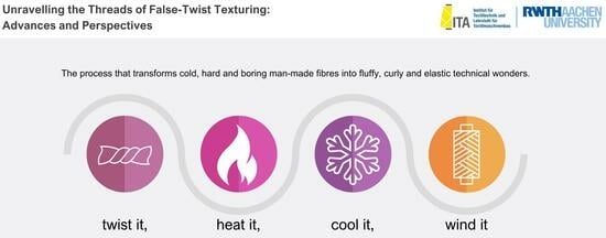


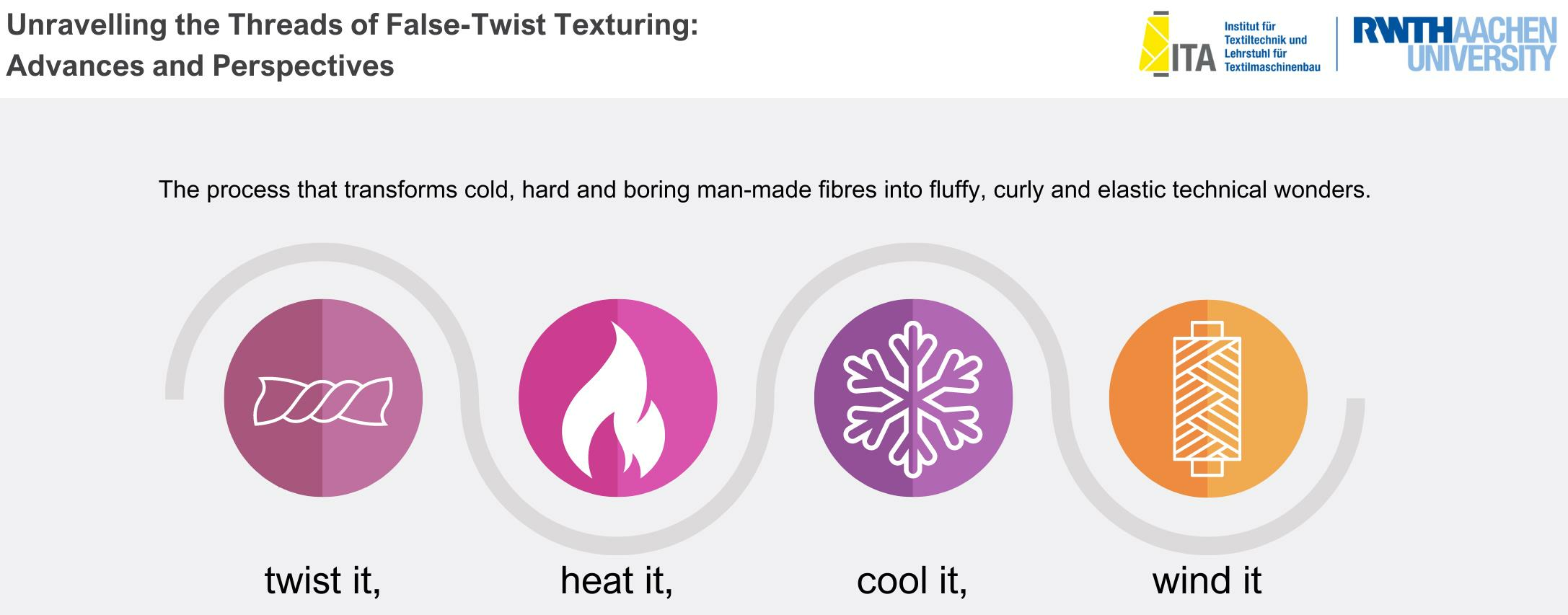
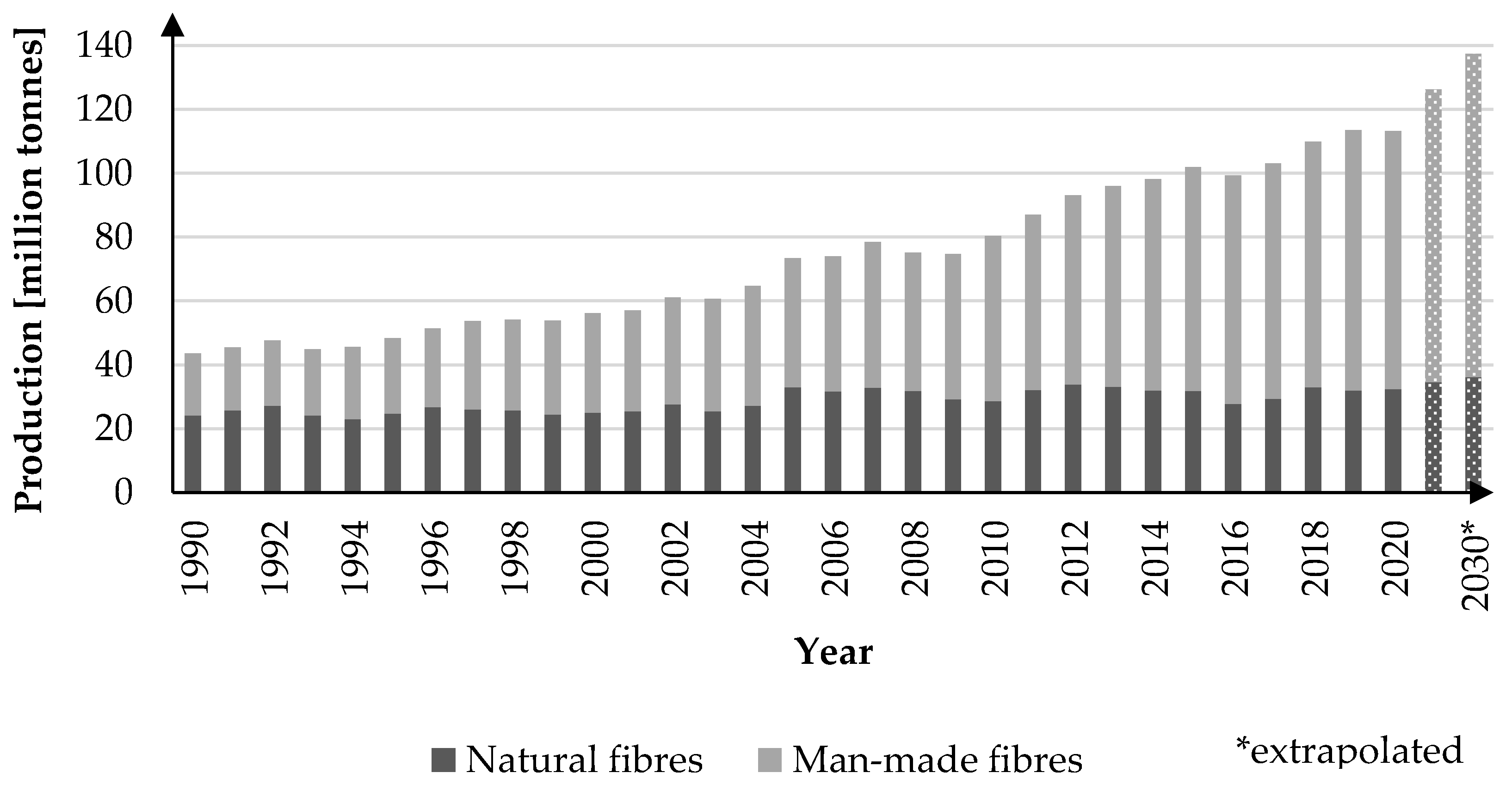
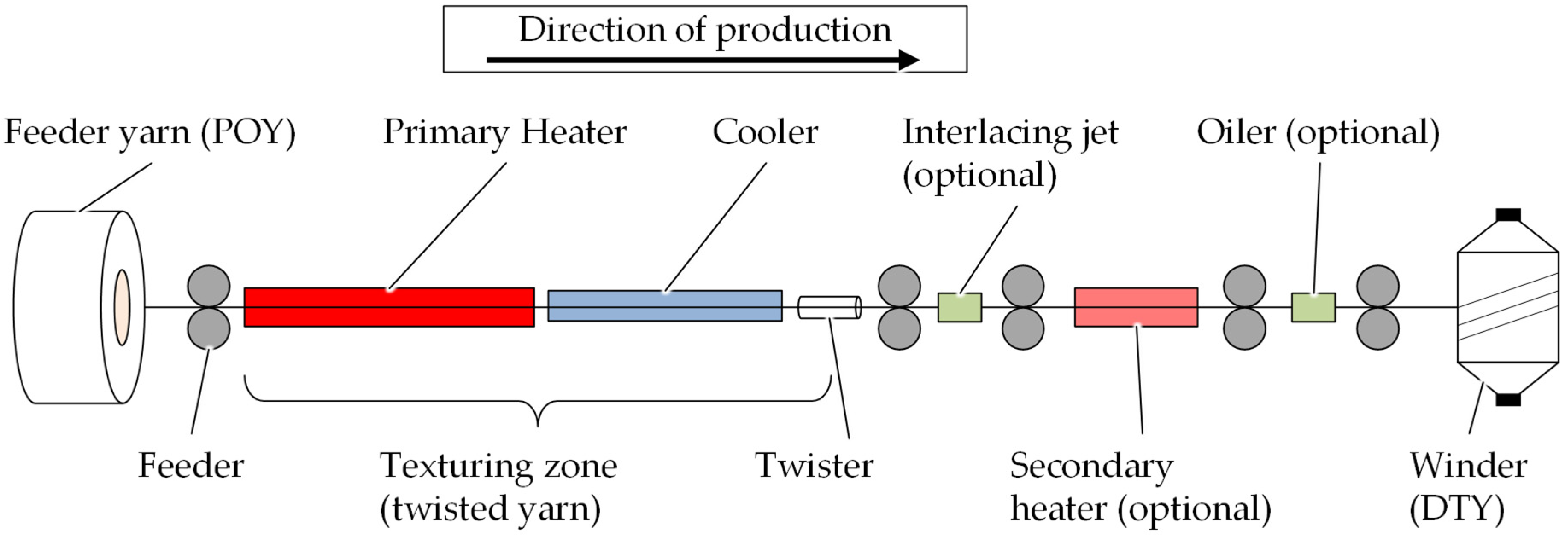
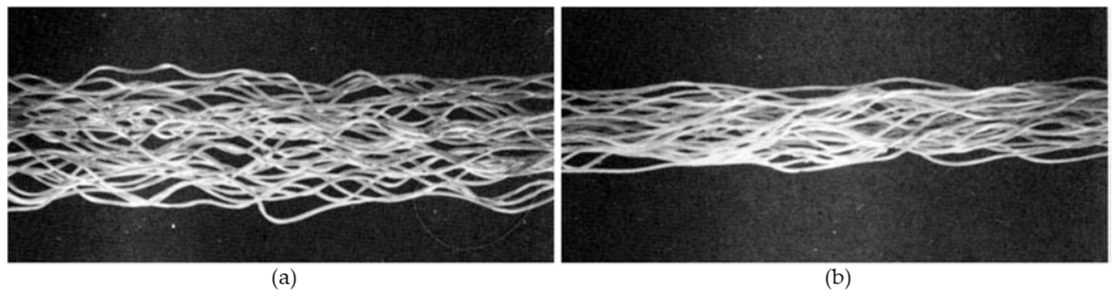
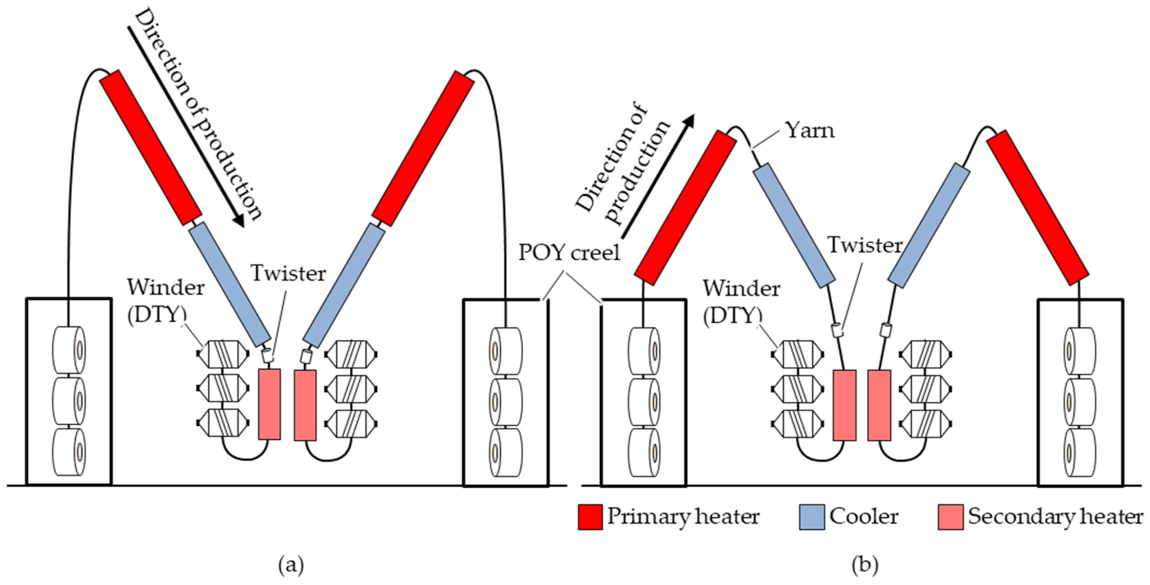
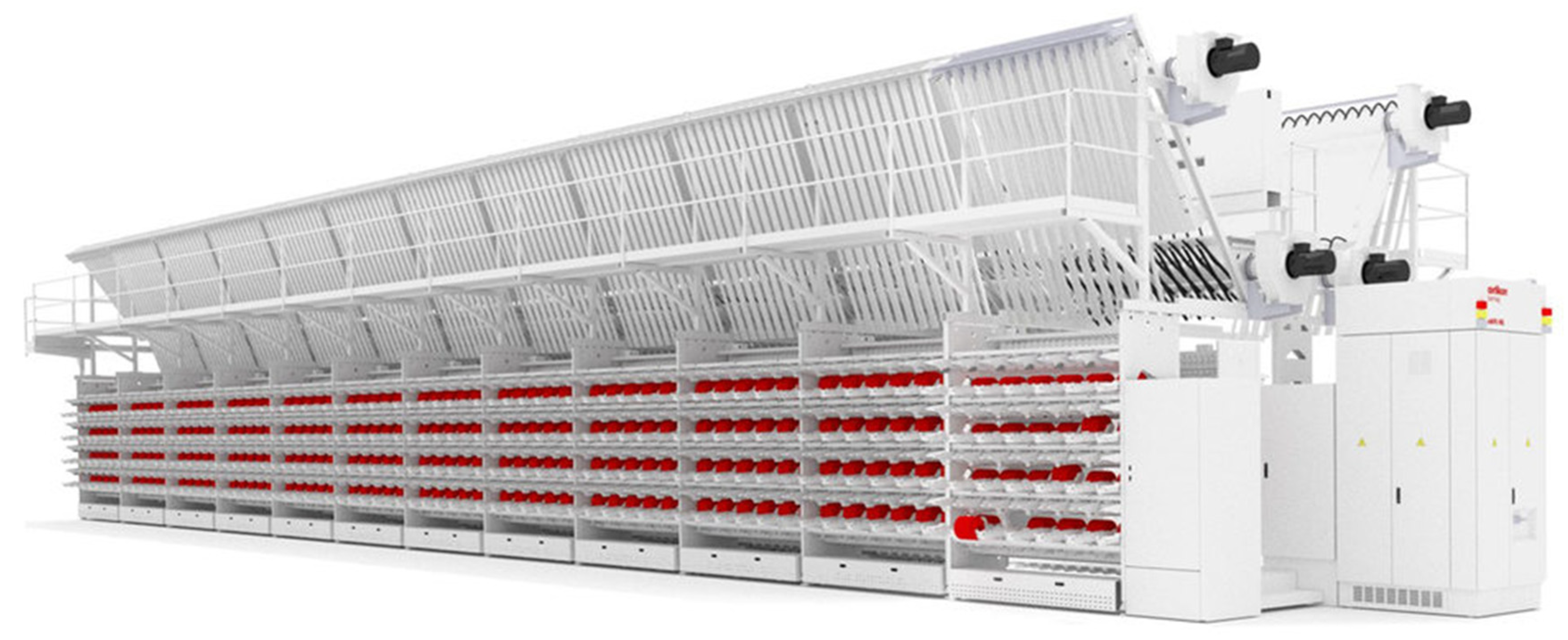
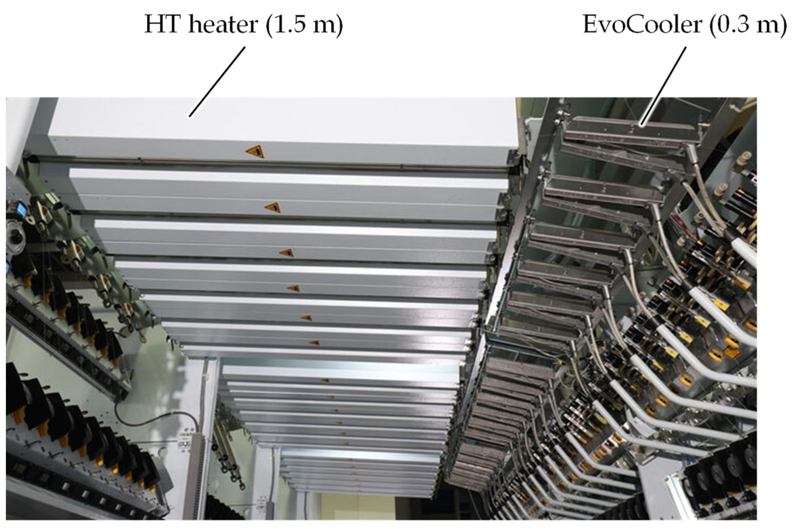
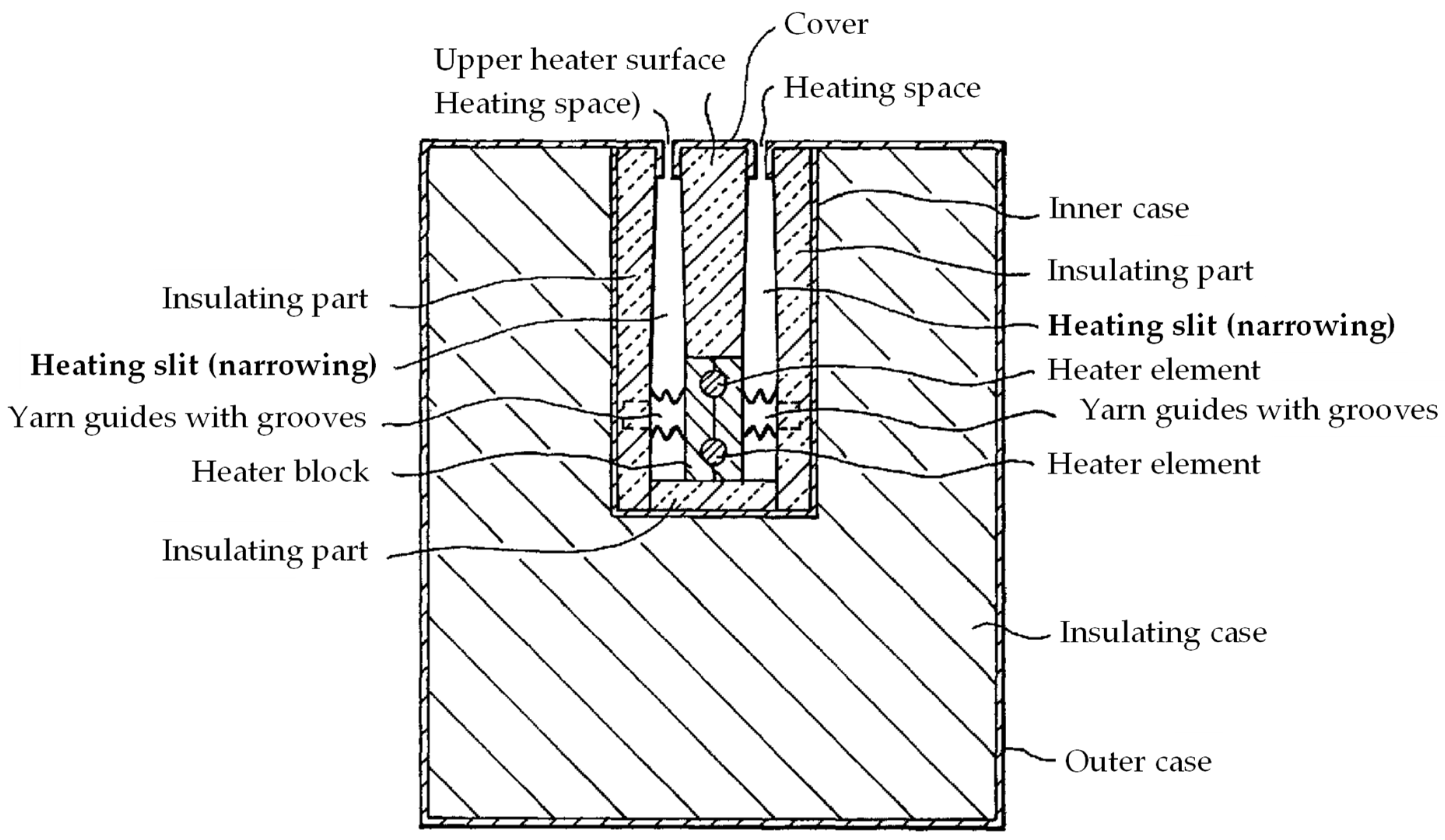
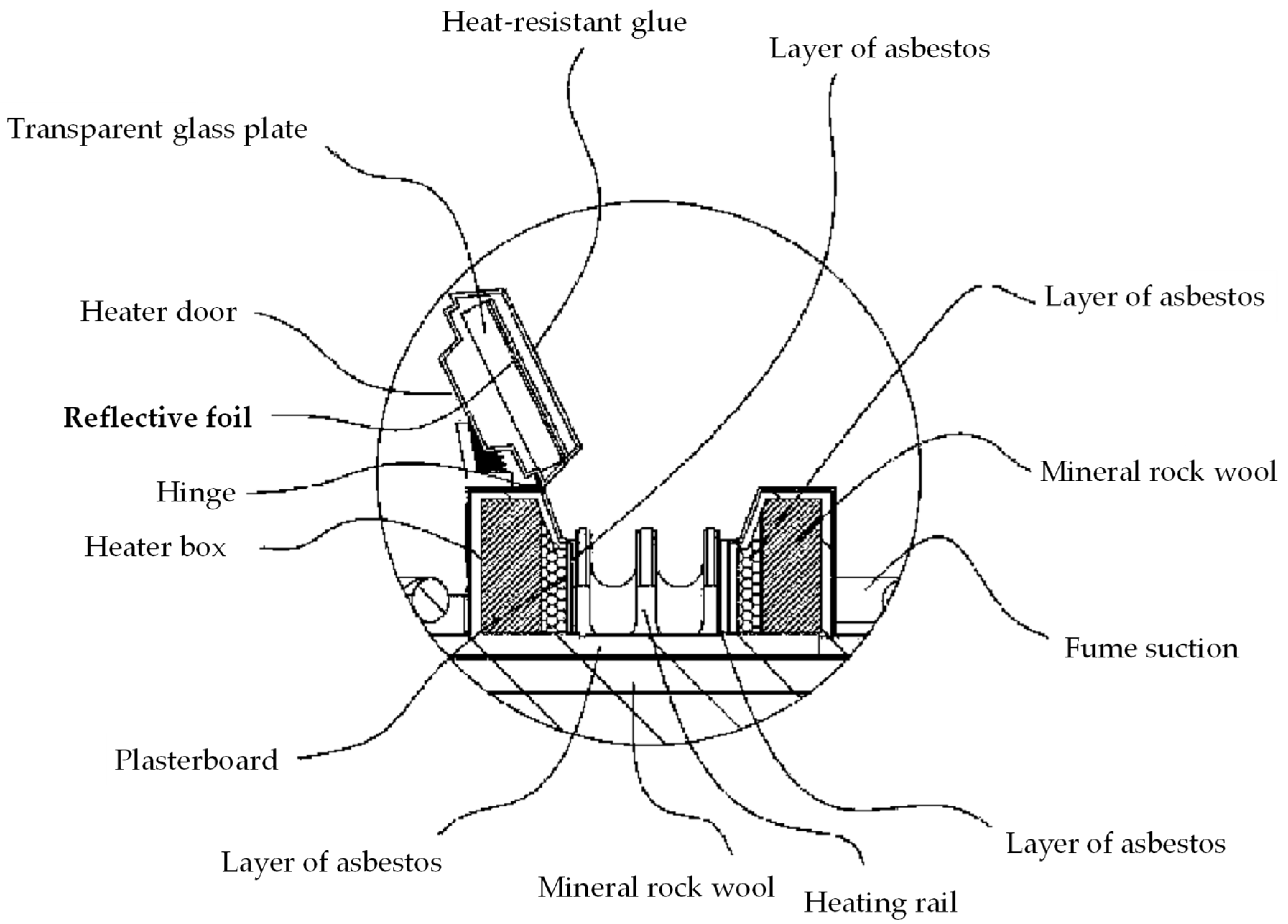
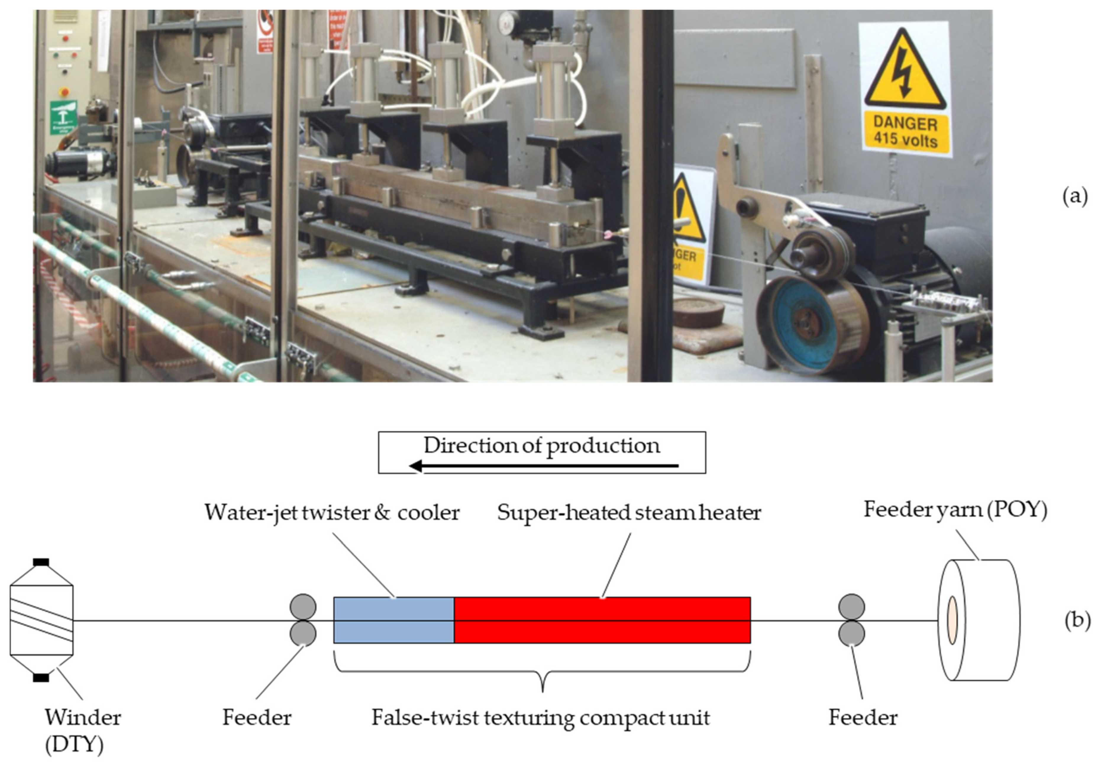
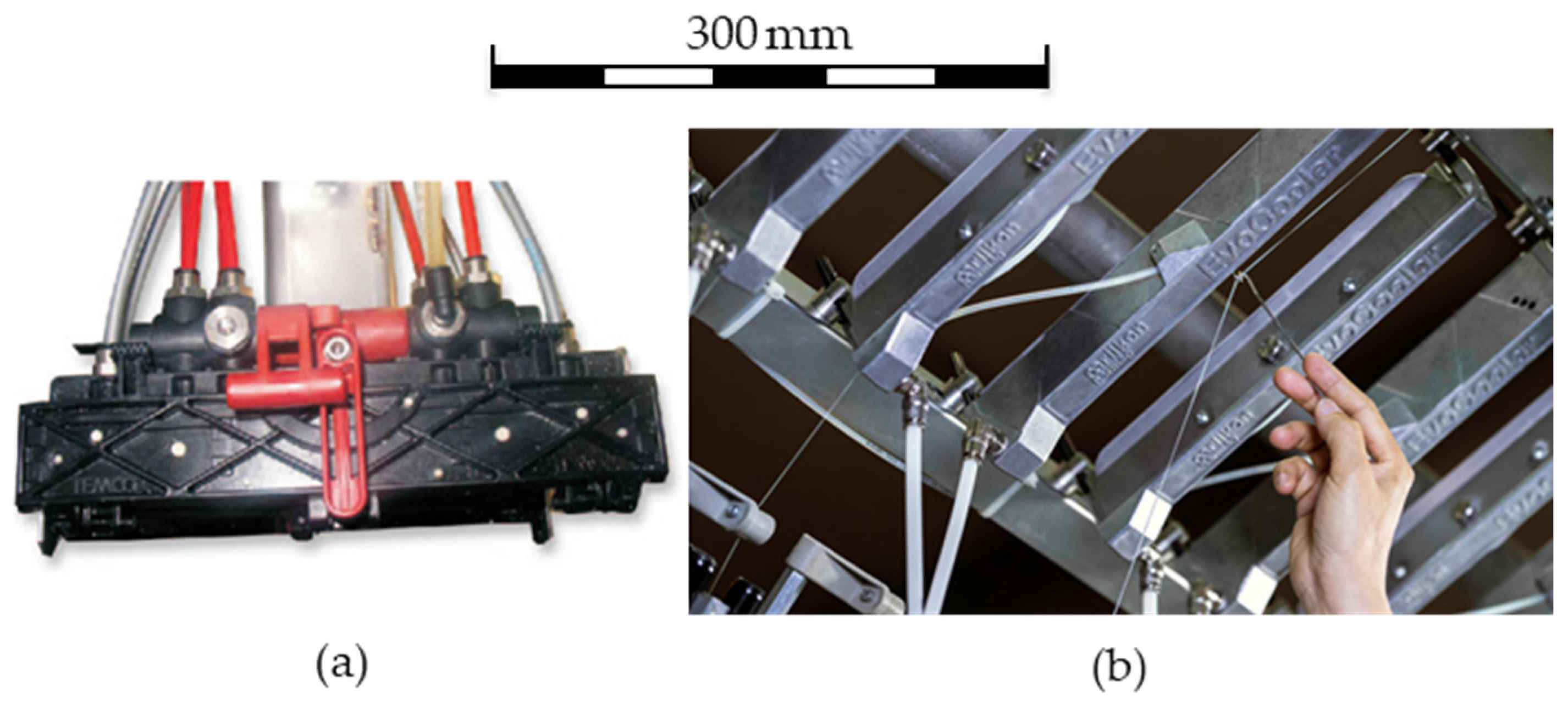
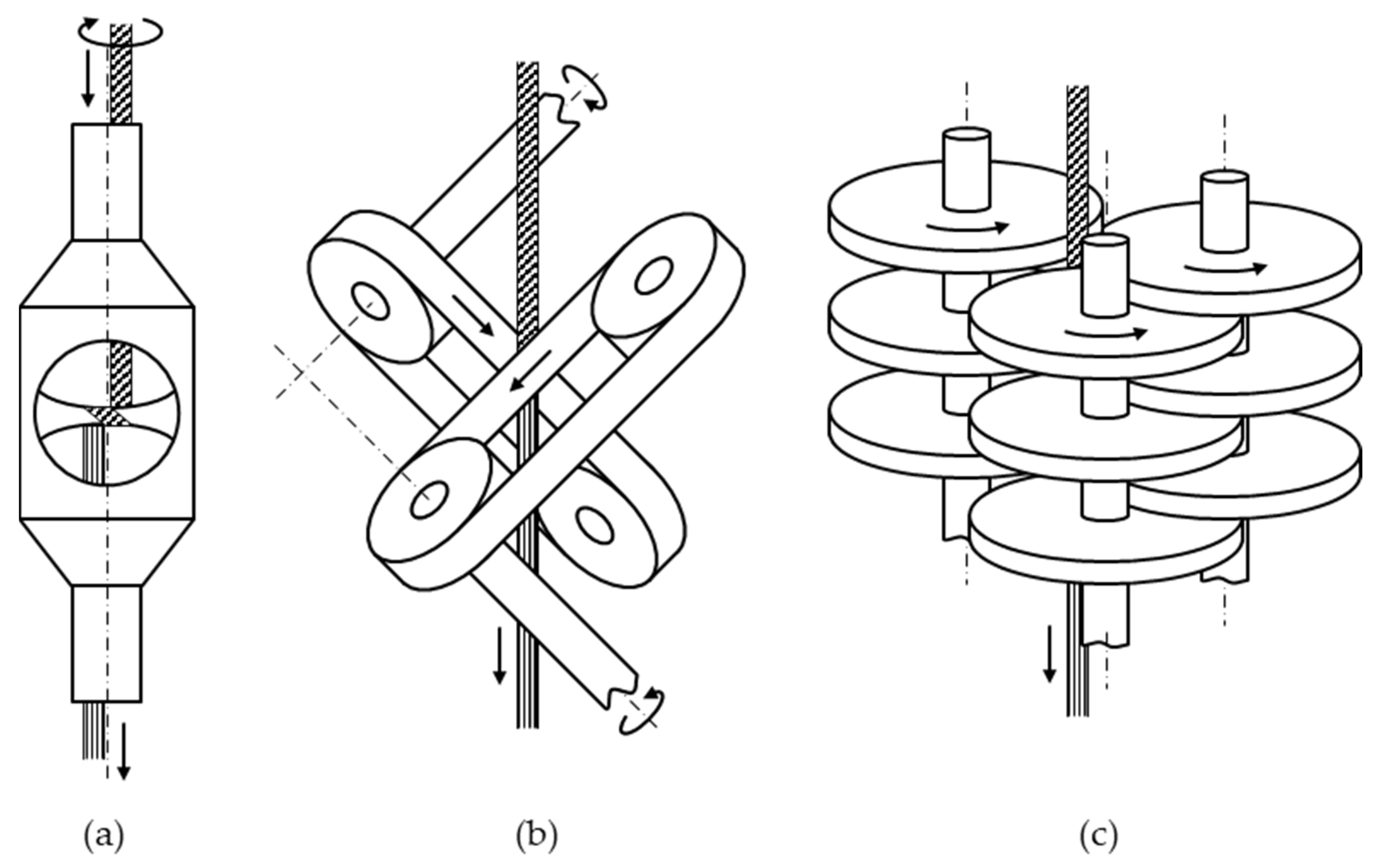
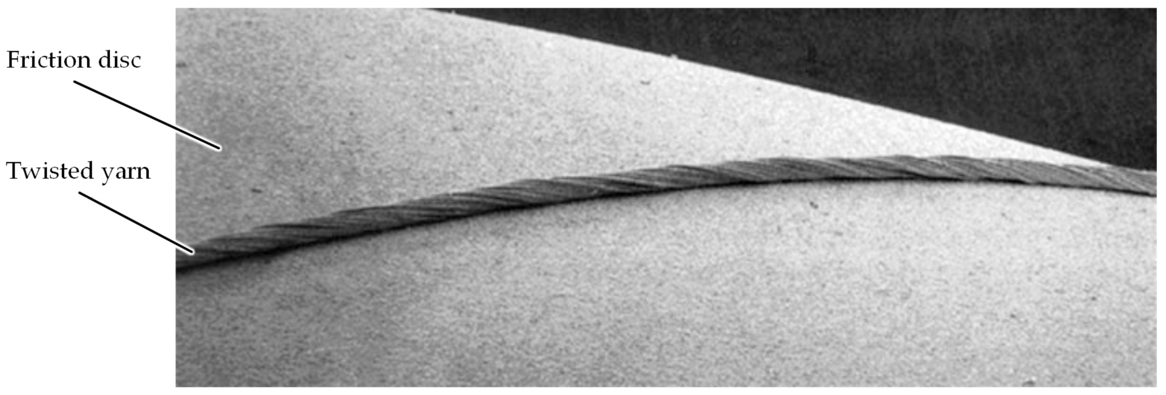
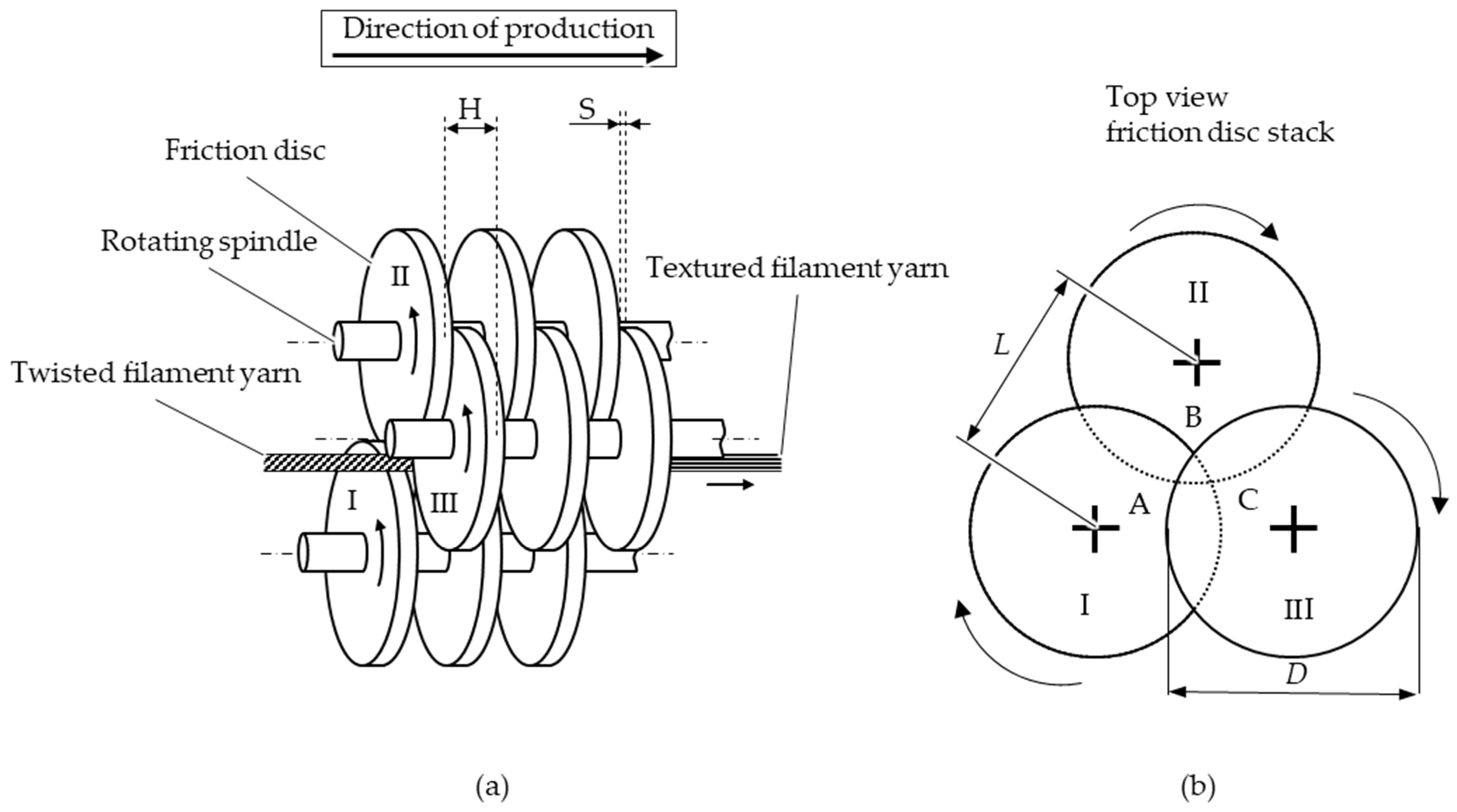
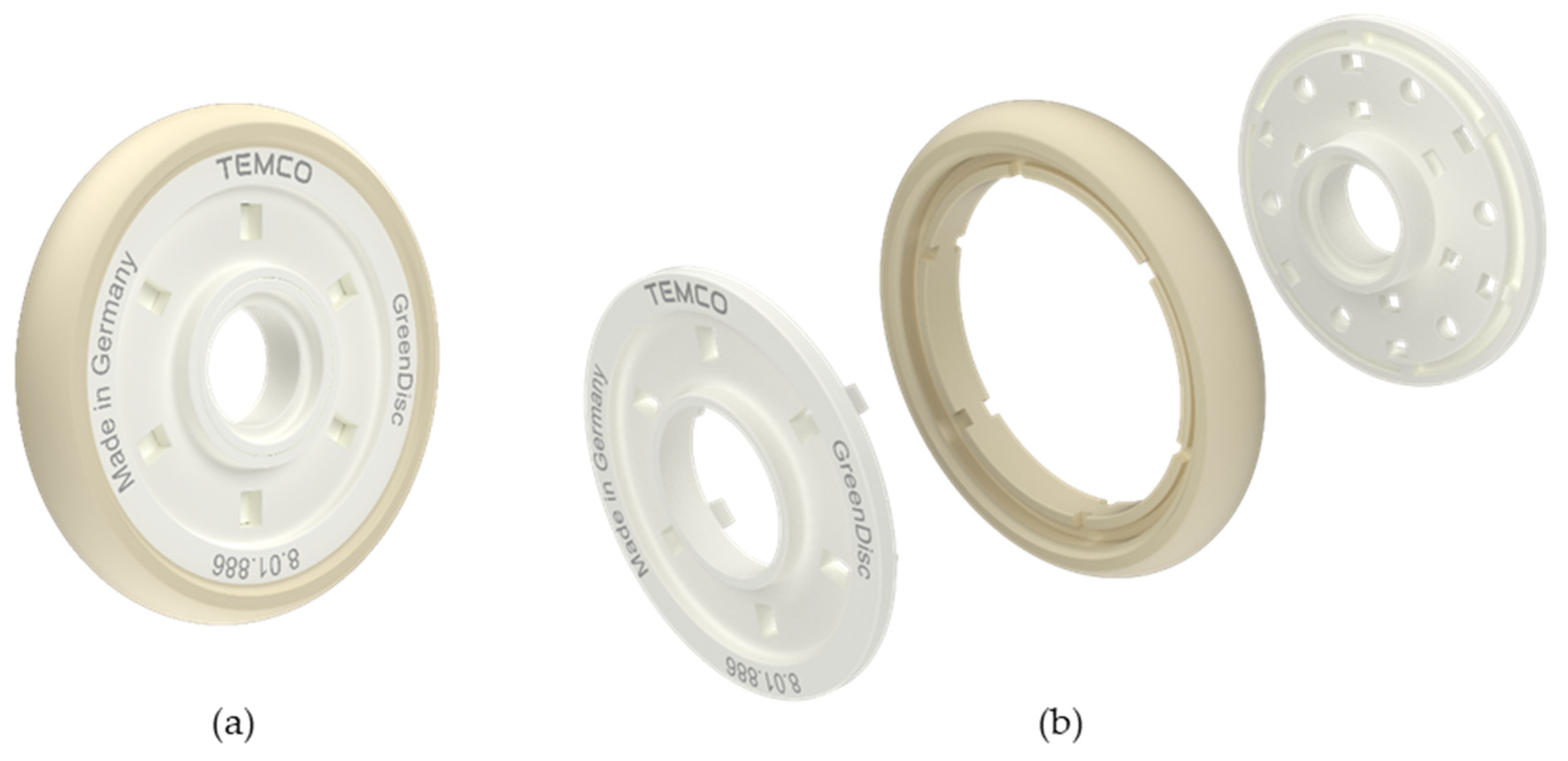
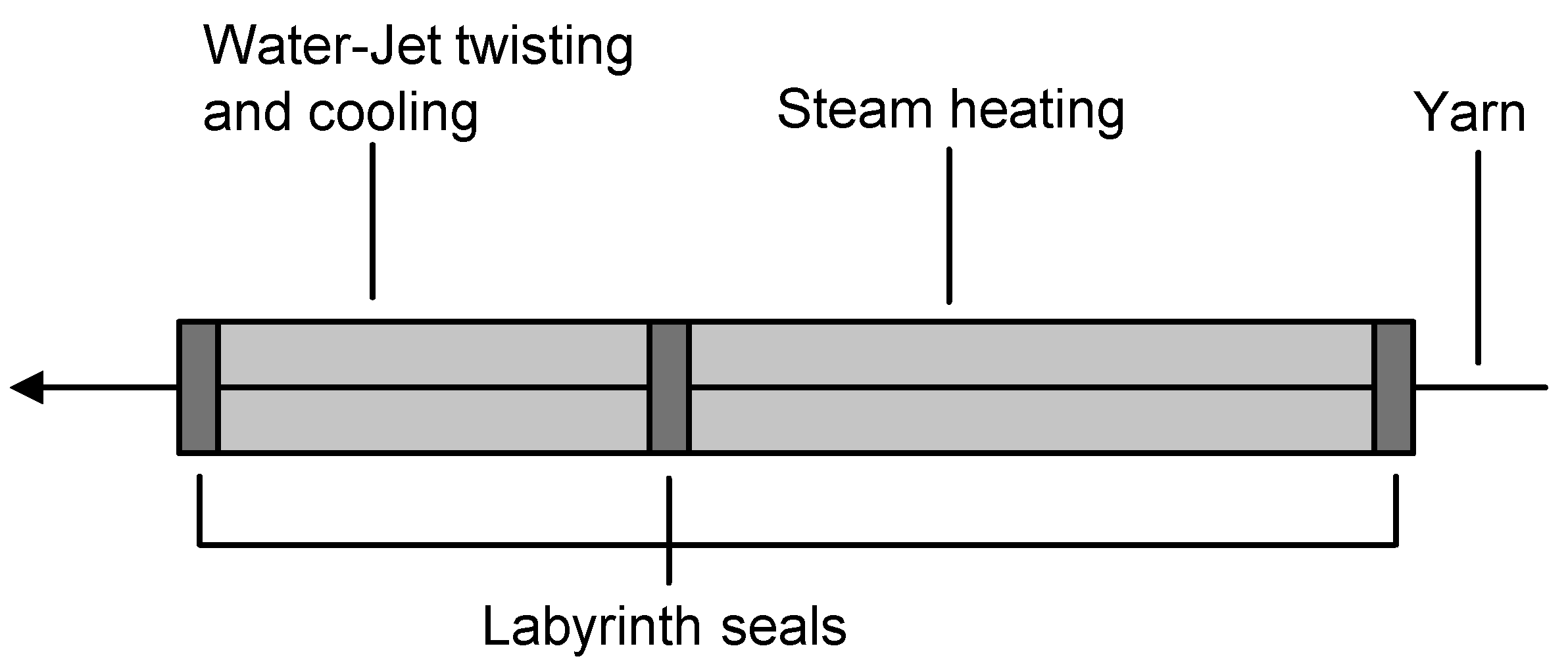
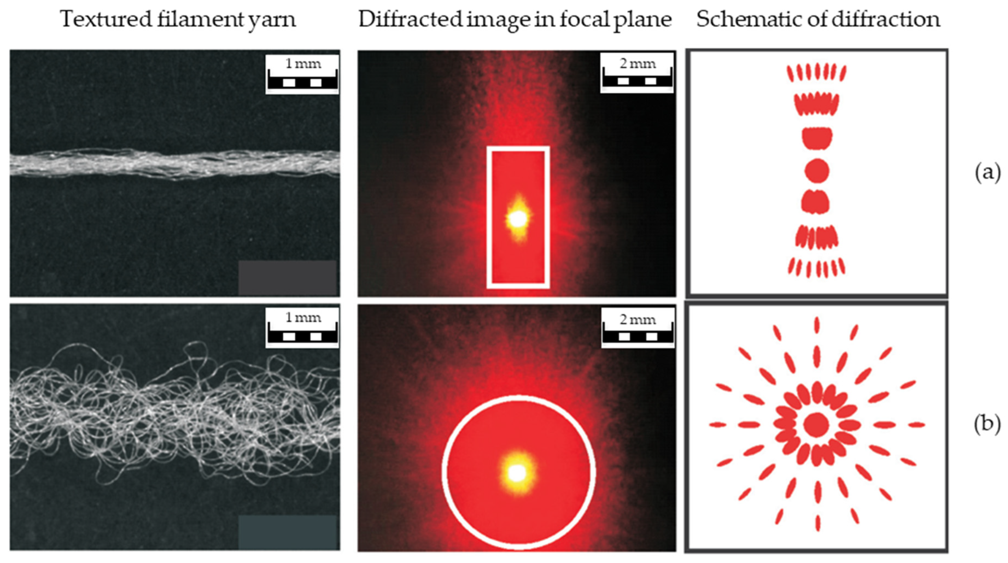
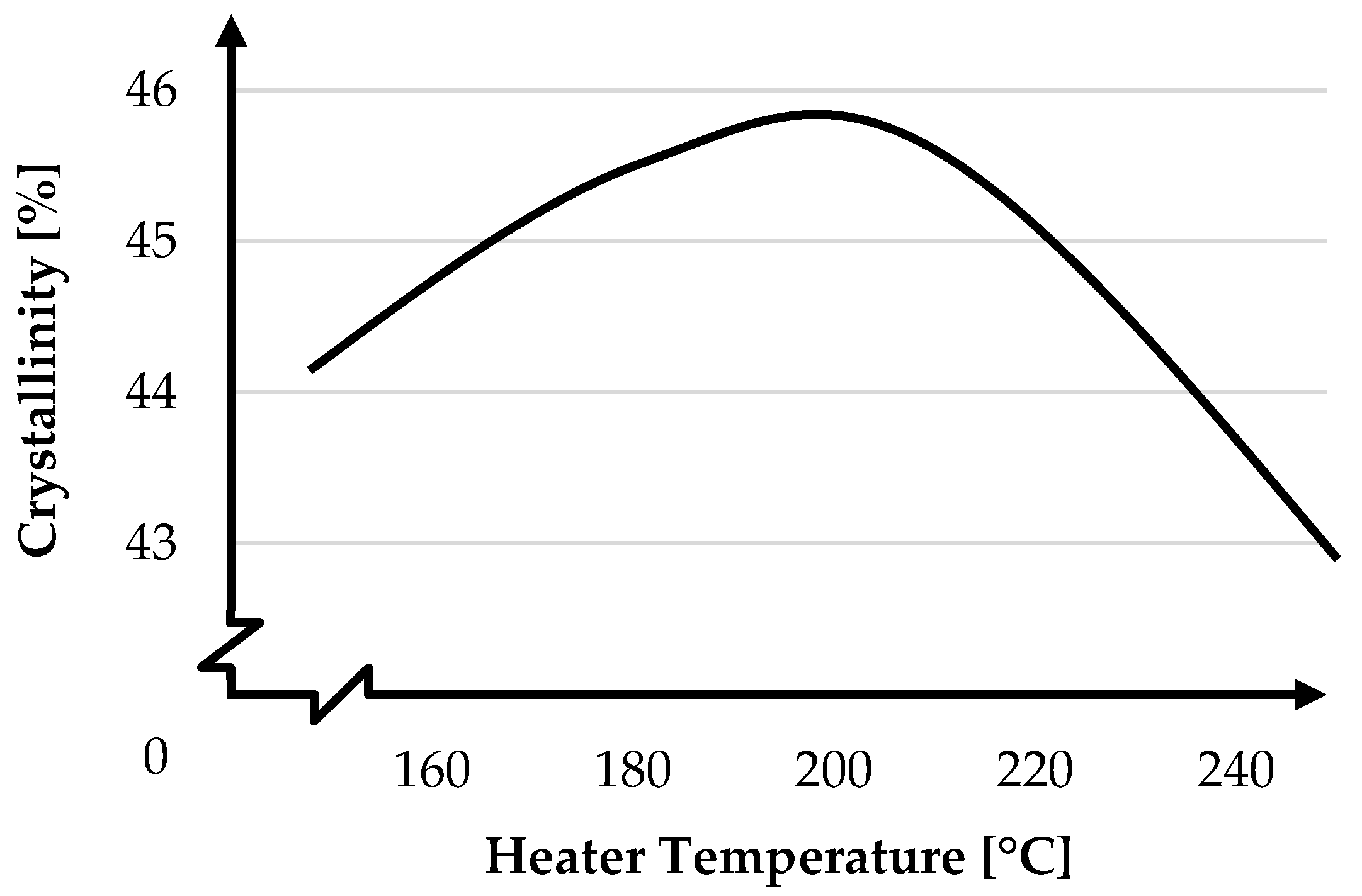
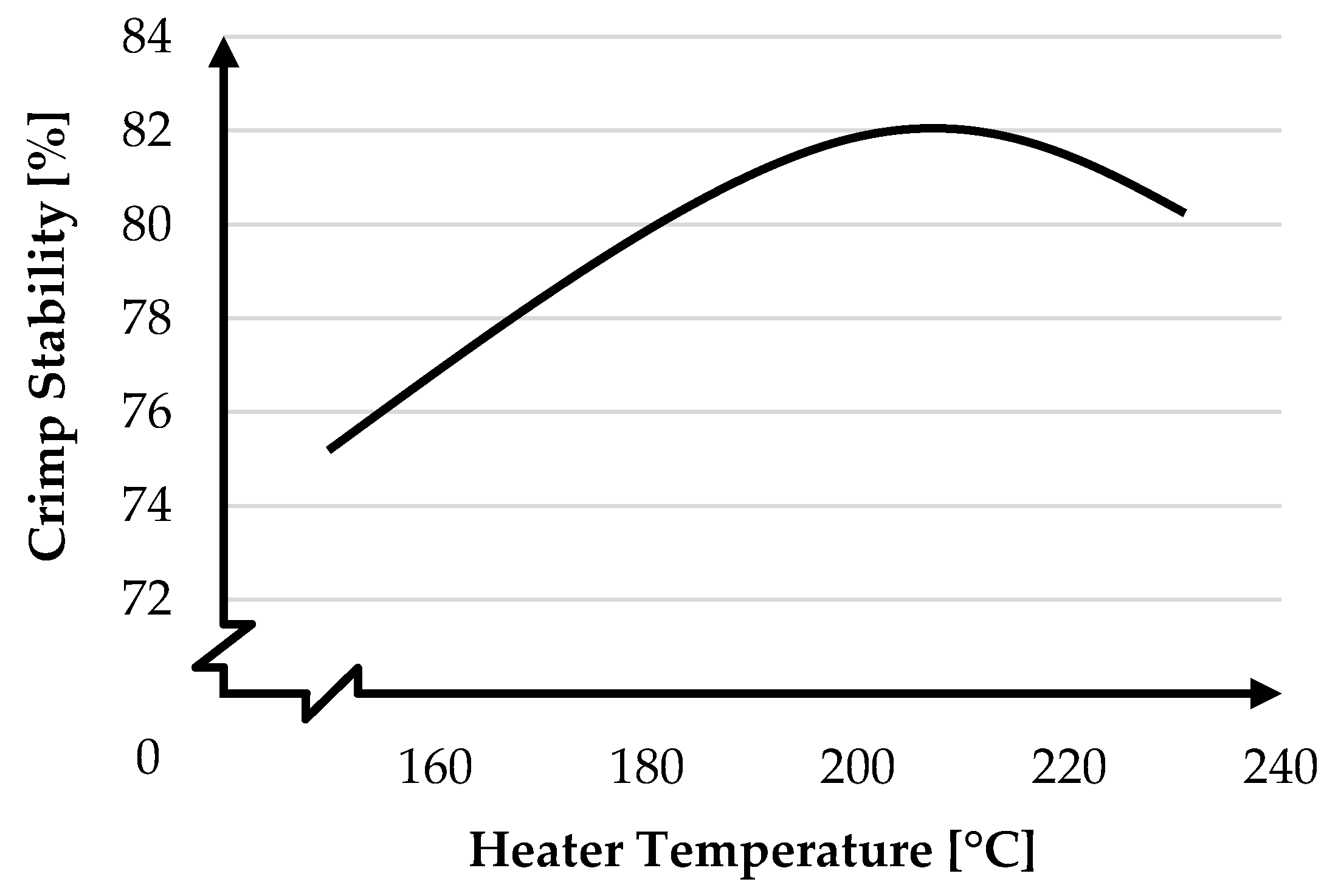
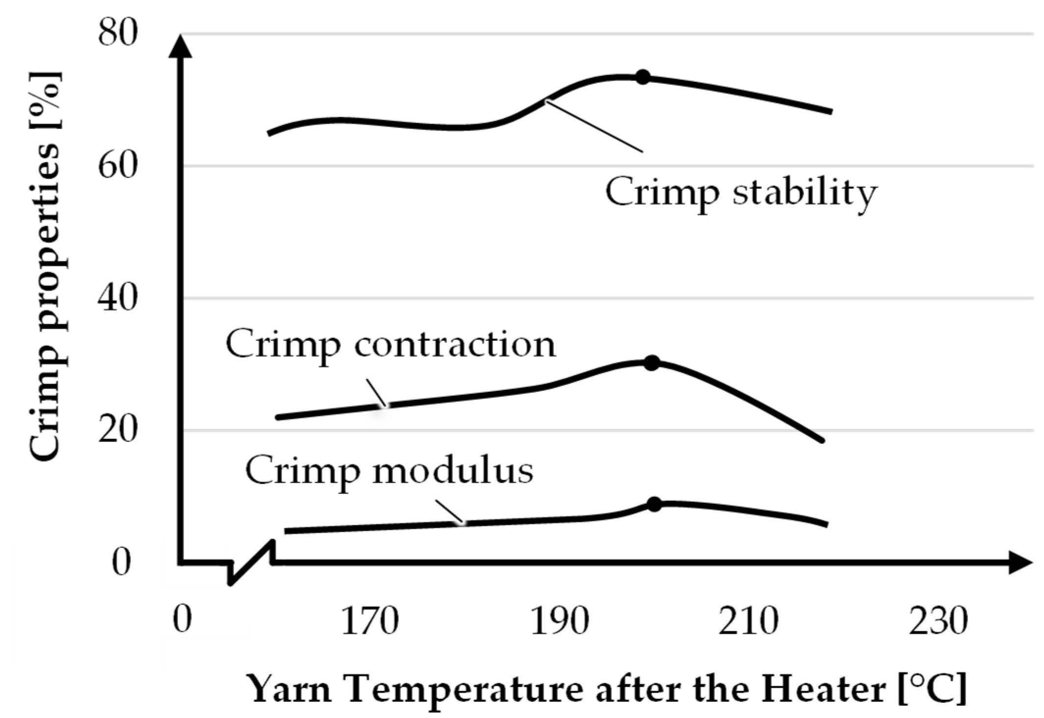
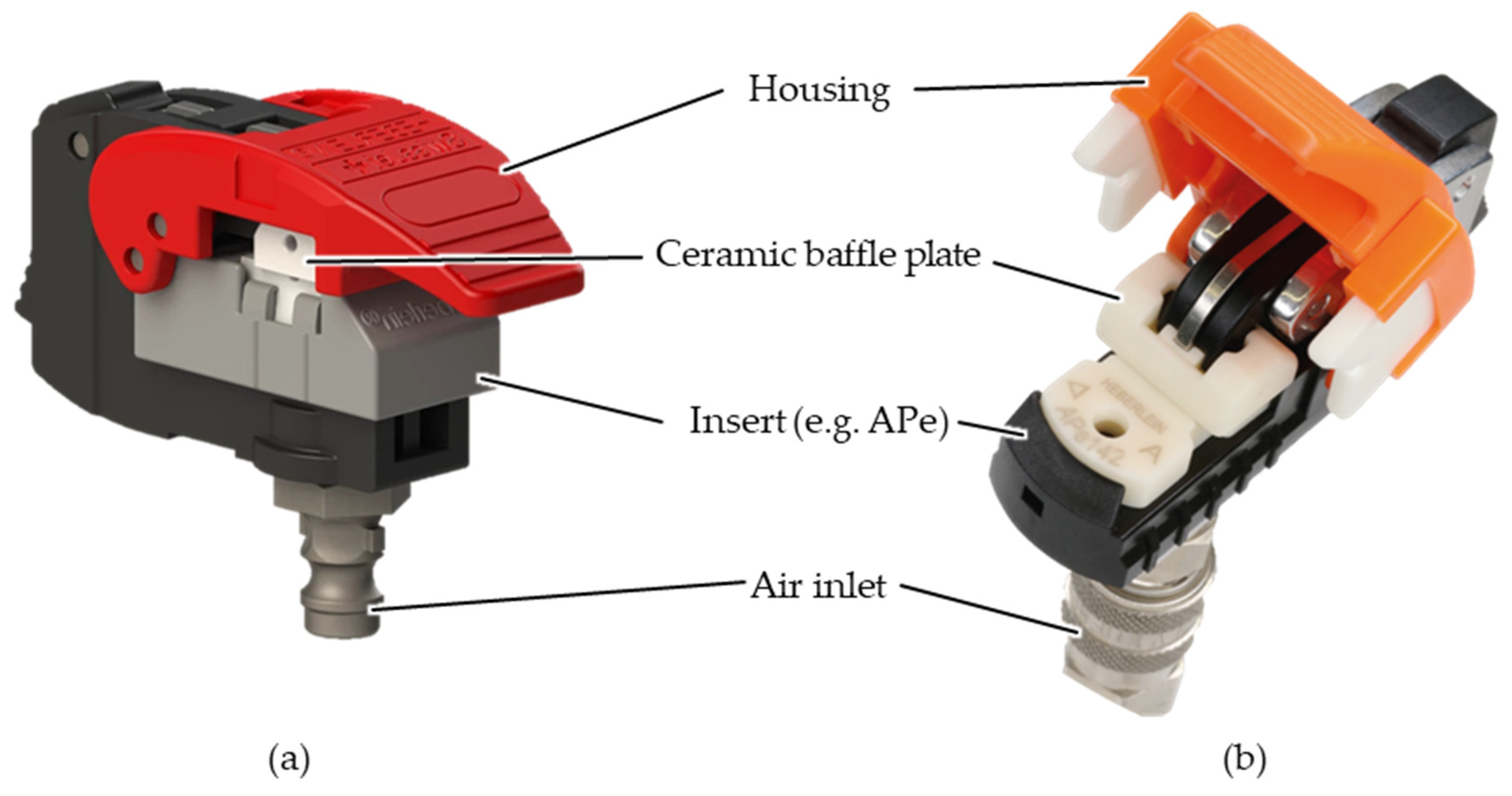
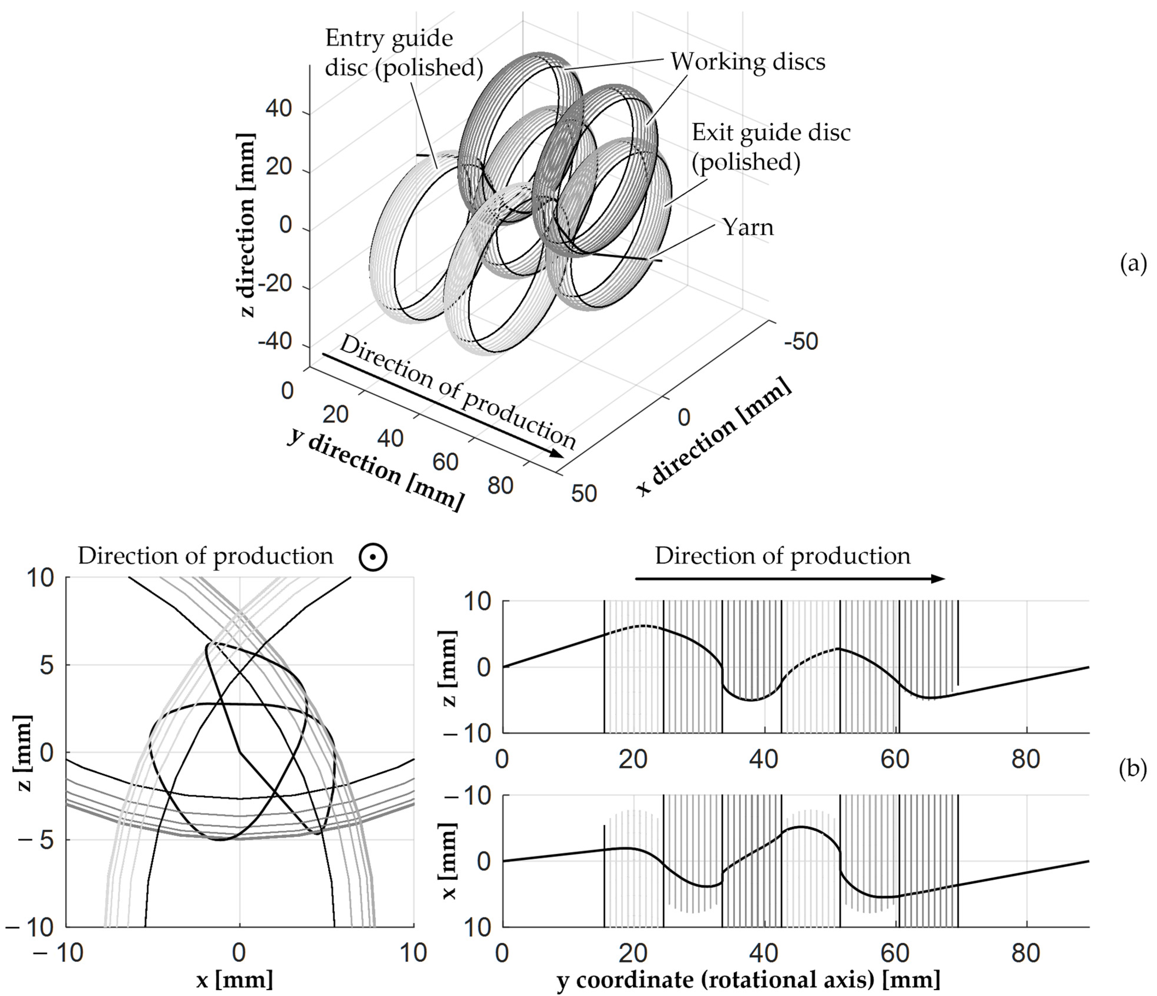
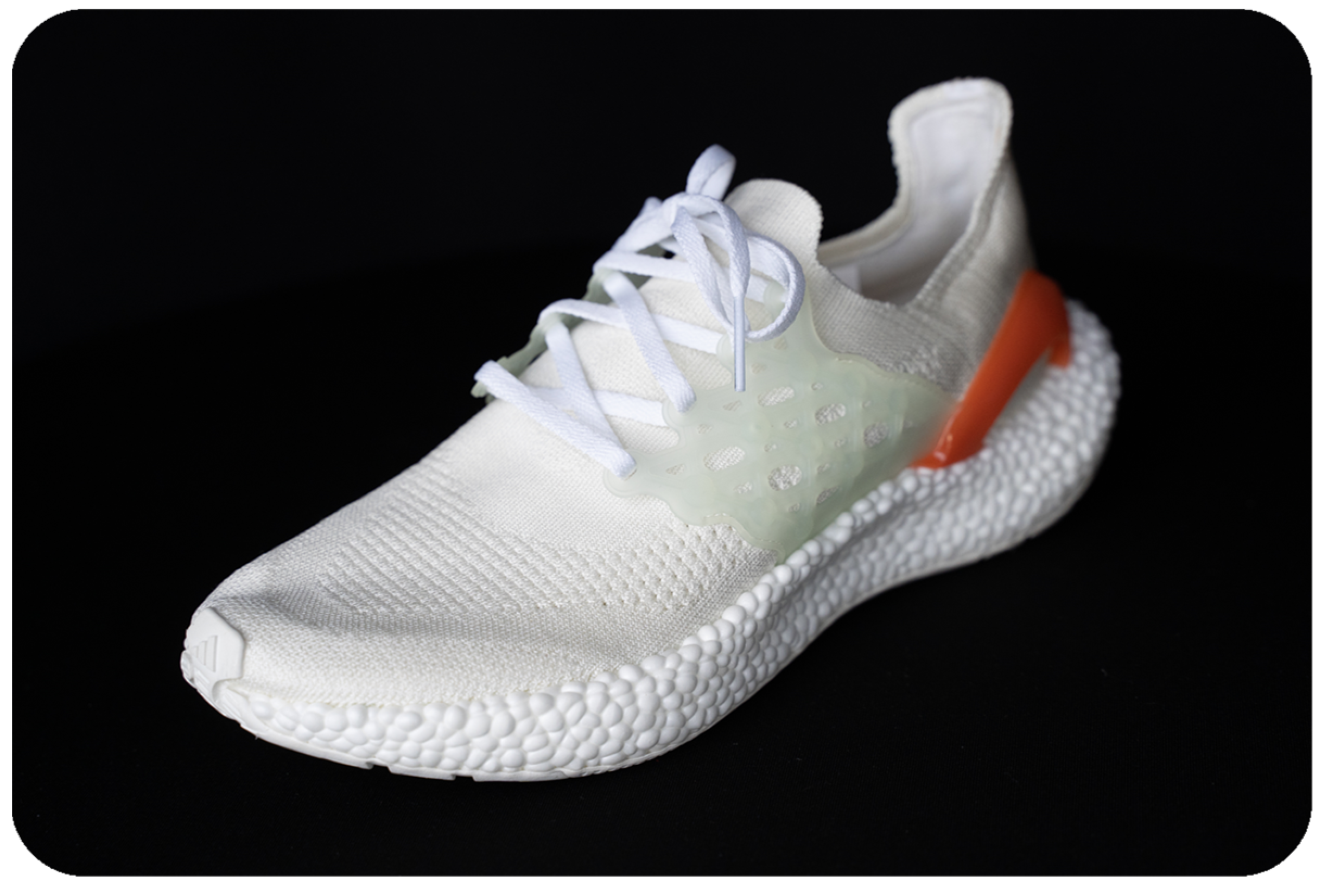
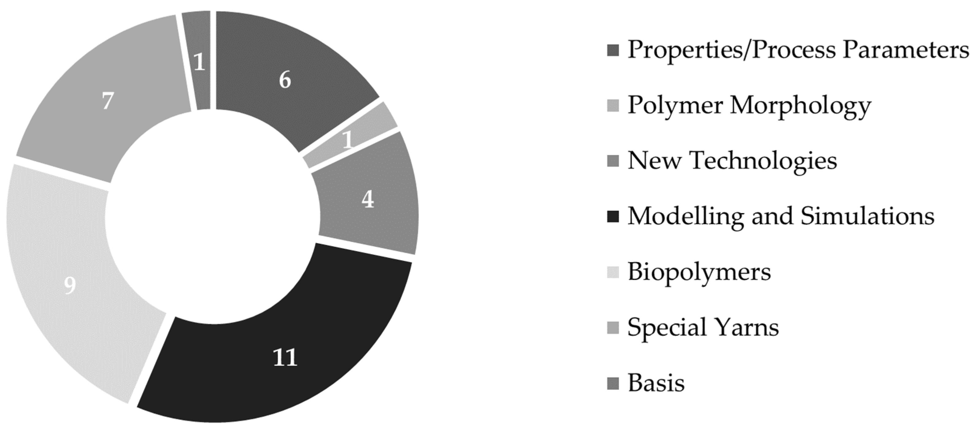