Article

On the Design of Permanent Rock Support Using Fibre-Reinforced Shotcrete

Division of Concrete Structures, KTH Royal Institute of Technology, 114 28 Stockholm, Sweden
*
Author to whom correspondence should be addressed.
Fibers 2023, 11(2), 20; https://doi.org/10.3390/fib11020020
Submission received: 7 December 2022 / Revised: 13 January 2023 / Accepted: 13 February 2023 / Published: 16 February 2023

Abstract

:
Fibre-reinforced shotcrete (sprayed concrete) is one of the major components in the support system for tunnels in hard rock. Several empirical design methodologies have been developed over the years due to the complexity and many uncertainties involved in rock support design. Therefore, this paper aims to highlight how the choice of design methodology and fibre type impacts the structural capacity of the lining and the emission of greenhouse gases (GHG). The paper starts with a review of different design methods. Then, an experimental campaign is presented in which the structural performance of shotcrete reinforced with various dosages of fibres made of steel, synthetic and basalt was compared. A case study is presented in which the permanent rock support is designed based on the presented design methods. Here, only the structural requirements were considered, and suitable dosages of fibres were selected based on the experimental results. The emission of GHG was calculated for all design options based on environmental product declarations for each fibre type. The result in this paper indicates that synthetic fibres have the greatest potential to lower the emissions of GHG in the design phase. Moreover, the choice of design method has a significant impact on the required dosage of fibres.

1. Introduction

The ongoing strive to reduce the construction industry’s climate impact has led to innovative solutions with respect to construction methods, new materials and more detailed and reliable inspection systems. The European Union (EU) has set an ambitious goal of being climate neutral by 2050. This means that our total emission of greenhouse gases (GHG) should be equal, or less, than the planet’s absorption capacity of GHG. At the same time, cities continue to expand, and the infrastructure network capacity must therefore increase. Thus, owners, engineers and contractors within the building industry face a complex challenge to reduce the environmental impact. Within this context, efforts are being made to reduce the high impact of shotcrete used to support tunnels and increase its durability. Moreover, Johansson et al. [1] investigated the feasibility of replacing the traditionally used rock bolts made of steel with glass-fibre bolts. Fixed markers could be applied to the shotcrete surface to achieve better control of the shotcrete (sprayed concrete) thickness. However, it was shown by Bjureland et al. [2] that the relative variation in thickness is considerable and that there is a tendency to use too much shotcrete. One way to improve control of the thickness and to reduce the use of the material was shown by Westlesen and Krutrök [3]. Here, a LiDAR sensor was mounted on the spray robot, which first scanned the rock surface and then the shotcrete surface directly after spraying. A map of the shotcrete thickness is presented to the operator for immediate control of thickness. Furthermore, the possibility of using ground-penetrating radar to determine the thickness of the concrete lining is summarized in, e.g., [4]. For inspections, the scientific community now focuses on using mobile mapping systems in combination with deep learning to increase the efficiency of inspections; see, e.g., [5,6].
For tunnels excavated in hard rock, fibre-reinforced shotcrete (FRS) in combination with rock bolts has been the dominating support method since the 1980s [7]. The main reason is the time saved in the production stage since using FRS removes the time-consuming work of placing traditional reinforcement. The structural behaviour of an excavated rock mass is difficult to predict due to the many uncertainties, such as the quality and orientation of the joints in the rock mass. Therefore, designing a suitable rock support is a complicated task. For these reasons, the design is often based on a combination of empirical methods and numerical analysis, and many countries have also developed individual strategies and empirical knowledge for the structural design of rock support. This also includes the type of fibre that can be used as reinforcement in the shotcrete. In Norway, synthetic and steel fibres were previously allowed for tunnels on land, while synthetic fibres were the only fibre for subsea tunnels due to durability aspects. However, after incidents where fibres floated to the surface and polluted the ocean, synthetic fibres were banned as of November 2015 [8]. The problem was initiated due to the combination of two factors: on the one hand, allowing tunnel mock, including shotcrete and fibres to be used as filling material in the sea, and on the other hand, the low density of those synthetic fibres allowed them to float to the surface.
In Sweden, even though it is not explicitly stated in the design rules, steel fibres are currently the only type of fibre that is commonly accepted as reinforcement in shotcrete used as tunnel support. The main reason for this is the great theoretical and empirical knowledge regarding the structural behaviour and durability of steel fibres built up since the 1980s [7,9,10,11,12,13]. In Australia, synthetic and steel fibres are used, and according to Bernard [14], the lack of familiarity with the material is one possible reason for the strict difference between using or not using synthetic fibres. Besides steel and synthetics, fibres made of basalt came into use for civil engineering applications in the 1990s [15]. Since basalt fibres are non-corrosive and are produced from basalt rock, they have been considered an environmentally friendly fibre. Research on structural behaviour, durability and environmental impact of basalt fibres are presented by, e.g., Mohaghegh [16], Afroz et al. [17] and Fiore et al. [18]. In the design of a tunnel, the choice of fibre can potentially reduce the environmental impact from the construction of tunnels and perhaps during the entire tunnel lifecycle. However, even though the tunnel’s environmental impact is important, one must also ensure that the alternative fibres fulfil the requirements put on the tunnel lining in terms of structural capacity, deformation and durability. These questions are investigated in an ongoing research project at KTH Royal Institute of Technology with support from the Swedish Transport Administration (Trafikverket). The project aims to investigate which fibre types are suitable for use in a road- and railway tunnel in hard rock.
This paper focuses on the design of fibre-reinforced shotcrete with respect to the structural capacity and the environmental impact of different types of fibres, i.e., steel, basalt and synthetic. Therefore, a review of different design methods is presented in Section 2, which includes an investigation and discussion on the correlation between the classification of the rock mass with the Q-system and rock mass rating (RMR) system and the required shotcrete thickness and fibre dosage. Some national empirical guidelines and analytical equations are also presented. An experimental campaign investigated the residual strength and energy absorption capacity of steel, basalt and synthetic fibres with various dosages. The content of the experimental campaign is presented in Section 3. To highlight how the choice of fibre and design philosophy of the rock support affects the required dosage of fibres and environmental impact, a case study is presented in Section 4. With the help of environmental product declarations (EPD), the global warming potential (GWP) for each design method and fibre type was calculated, which links the design method, fibre type and environmental impact for the construction of a tunnel. The results from the experimental campaign and the case study are presented in Section 5, which is followed by conclusions.

2. Design of Shotcrete as Permanent Rock Support

As mentioned above, tunnels in hard rock are commonly supported with a combination of rock bolts and fibre-reinforced shotcrete. For the design of shotcrete, the necessary thickness and ductility, often specified as energy absorption or residual flexural strength, must be decided. This is by no means a trivial task since the load acting on the shotcrete depends on the deformation of the rock mass and its interaction with the shotcrete. As mentioned above, rock support design is complex; therefore, the design codes used in Europe, i.e., Eurocode 7 [19], are open for various design methods such as empirical, analytical, and observational methods. The design methodology differs between projects and individual engineers. As with the choice of material for fibres, the choice of method will likely come down to the engineer’s familiarity and trust in different methods as well as the governing design rules. However, as discussed below, the choice of the design method will impact which mechanical properties the shotcrete must fulfil and, thereby, which test methods are suitable for quality control during construction. In, e.g., Sweden, shotcrete has traditionally been specified with a required residual flexural strength which prohibits a stringent use of an empirical design method such as the Q-method, while in other countries, e.g., Norway, empirical methods are commonly used in the design. Below, different design approaches are described, including the Q- and RMR method, national guidelines, and analytical equations.

2.1. Design with the Q-Method

Design of rock support with empirical methods is normally based on a rock mass classification system. Two widely used systems are the rock mass rating (RMR) system, developed by Bieniawski [20], and the Q-method, by Barton et al. [21]. In the Q-method, the rock mass quality Q is calculated based on the ratio between three sets of parameters. which represent the structure of the rock mass, the roughness and degree of alternation of the joints and active stresses [21].
Q = RQD J n × J r J a × J w SRF
The rock support is determined based on the Q-value and the equivalent dimension, which is the ratio between an effective length and the excavation support ratio (ESR). The effective length is determined for the roof and walls separately, and the ESR value reflects upon the tunnel’s purpose and degree of safety. In the original paper [21], the relevant values of and the equivalent dimension of the tunnel were studied together with the used rock support from more than 200 case records. Based on this, a design chart with 38 different support categories was presented. With the work by Terzaghi [22] and several case records as starting points, some theoretical reasoning is presented regarding the maximum support pressure that will develop. It is concluded that the support pressure will be independent of the dimension of the tunnel and hence only depend on the quality of the rock. Based on the fact that the support pressure P can be determined, the distance between systematically placed rock bolts a can be calculated based on the yield capacity of one bolt f bolt as:
a = f bolt P
However, determining the load acting on the shotcrete when combined with systematically placed rock bolts is far more complicated. The load distribution depends here on the interaction between shotcrete, rock bolts and the rock mass, and in the Q-system [21,23,24], the required thickness of the shotcrete is purely based on studied case records. Two significant updates of the Q-system have been performed and presented in [23,24]. In the first update [23], 1050 new cases were added, and fibre-reinforced shotcrete was included as one of the main components for rock support. The thickness is still based on empirical knowledge from case records, and no recommendations or requirements are given regarding the dosage of fibres. In the second update [24], 900 case records were added based on underground excavations in Norway, Switzerland and India [25]. Moreover, an energy absorption criterion for the shotcrete was introduced based on panel tests according to the EFNARC standard [26]; see Figure 1. Again, there is no thorough theoretical reasoning behind the correlation between Q-value, equivalent dimension and required energy absorption or regarding the borderlines between required energy absorption levels; see Figure 1. Furthermore, the Q-system gives a recommended length and spacing between bolts with and without fibre-reinforced shotcrete (denoted as Sfr in Figure 1).

2.2. Design with the RMR-Method

The rock mass rating (RMR) system was developed by Bieniawski [20] and has since then been updated several times; see, e.g., [27,28]. A more detailed historical review can be found in, e.g., [29,30]. The basic RMR value is based on the summation of six parameters representing the strength of intact rock, drill core rating (RQD), spacing of discontinuities, condition of discontinuities, groundwater and orientation of the discontinuities [31]. The basic RMR value is then adjusted based on blasting damage, in situ stress and major faults. The procedure is schematically shown in Figure 2. Unlike in the Q-method, the rating for each parameter used to calculate the RMR value is based on a specific range of values. For example, RQD and groundwater are within the range of 3–20 and 0–15, respectively. Based on the RMR value, the rock is divided into five different classes that range from very good to very poor rock, and a suggested rock support is assigned to each category; see Table 1. This gives the length and distance between the bolts as well as the thickness of the shotcrete. There are no requirements put on the energy absorption or residual strength of the shotcrete, and no theoretical reasoning is presented in connection to the suggested support system.

2.3. Design with the National Guidelines

In some countries, national recommendations have been developed based on practical experience from rock support design. During the same time that a second update of the Q-system was ongoing, a correlation between Q-value, rock class and toughness performance level (TPL) was proposed by Papworth [32] based on experience. Here, the definition of toughness performance level (TPL) [33] is used in which fibre-reinforced shotcrete is classified into levels I–V based on the residual flexural strength at fixed vertical displacements. The TPL is based on testing according to the now withdrawn standard ASTM C1018. Here, the free length of the specimen was 300 mm, and the residual strength was thereby determined between the vertical displacement δ 1 = 0.5 mm and δ 2 = 2.0 mm. The limits between TPLs are defined as a ratio of the flexural strength f re for the shotcrete. In Table 2, the ratios and the numerical values for a case with f re = 4.0 MPa are both presented [33]. In each TPL, the upper limit is the f re at δ 1 . In Sweden, a preliminary rock support design is often based on the Q-method. Then, numerical simulations or analytical equations are used to verify the structural capacity of the support. In such cases, the residual strength of the shotcrete is needed, and this is commonly set as f re SWE between 3.5 and 4.0 MPa at 2.0 mm deflection [34], based on the EN 14488-3 test standard [35]. In the Australian guidelines for the design of shotcrete [36], it is recommended to specify a required residual flexural strength when small deformations are expected or accepted and an energy absorption criterion otherwise. In the guideline, no limit is defined when displacements are considered to be small. Typical values from civil engineering projects are for small deformations f re AUS   = 3.0 MPa at 3 mm vertical deflection for the EN 14488-3 test [34] and for large deformations 400 J for the RDP test [7]. For the example in this paper, it has been assumed that a design based on small deformations is suitable for rock class A and B, while large deformations should be assumed for the design of the remaining rock classes; see Figure 1.
To summarize, a design based on the Q-method or the RMR system yields a required shotcrete thickness and a specific energy absorption if the Q-system is used. Quality control of shotcrete should therefore be based on testing of square panels [29] or round determinate panels (RDP) [37]. There is no thorough theoretical reasoning behind the required thickness or energy absorption in any of the systems. However, few cases of tunnel failure are reported in the literature, and for those Norwegian cases reported, e.g., Hannekleiv [38], the reason behind the collapses has been an overestimation of the rock quality. It can therefore be concluded that the empirical design methods yield a safe design in most situations. However, the design information gives no information regarding the level of safety of the structure.

2.4. Design with Analytical Equations

The primary support mechanism for shotcrete is that it should be able to carry the load from a small block, either through its bond to the rock surface or its flexural or shear capacity; see Figure 3. For a rock support with systematically placed rock bolts, the maximum size of the block could be determined based on the spacing between the bolts. For the design of shotcrete with analytical equations, many researchers, see, e.g., [7,39], refer to the work by Barrett and McCreath [40], where the potential failure modes for a bolt-anchored shotcrete lining subjected to a block-load are presented based on observation of experimental results from the literature [11,41,42]. Based on this, it was concluded that each failure mode could be treated individually, and analytical equations are presented for each failure mode. The independence of these modes was verified with numerical simulations by Sjölander et al. [43]. In this paper, only the design model for flexural failure will be discussed. The reason is that the other failure modes, i.e., shear and bond, are not directly affected by the fibre content in the design. Shear failures seldom occur when the thickness is greater than 40 to 50 mm [41,42]. Due to the high pressure used during application of shotcrete, coarse aggregate and fibres tend to rebound from the rock surface until a sufficient layer of cement paste has been built up. Thus, the bond strength is unaffected by the fibre content, and the rock surface’s characteristics and the shotcrete operator’s skill are the two most important parameters affecting bond strength.
In the rock support design phase, the shotcrete’s tensile strength is typically neglected, and the residual flexural strength is used instead. The reason is that fibre-reinforced shotcrete typically has strain-softening behaviour; thus, its load-capacity decreases after the first crack is formed. As a first step in the design, a mechanical model is applied. Since the fibres in the shotcrete are randomly distributed, it is assumed that the residual flexural strength of the shotcrete is the same in both in-plane directions. For this reason, designing the shotcrete based on a 2D model, which neglects the beneficial load distribution in two directions that occurs in a slab, is an assumption on the safe side. Thus, the design of the shotcrete is often based on a beam model, in which the block’s size and the beam’s length are determined based on the distance between the rock bolts. The moment capacity for the shotcrete is given by:
M Rd = W × f re
Here, W is the first moment of the area, and f re is the residual flexural strength which greatly depends on the fibre content. The design of the rock support then becomes a cost-optimization problem between rock bolts, shotcrete thickness and fibre content.
For a case when the design is based on analytical equations, in situ quality control must be performed based on beam tests to verify that the correct f re is achieved. According to EN 14487-1 [44], a minimum of three beams should be tested for every 500 to 2000 m2 of shotcrete sprayed. One of the drawbacks of this test method is that the scatter in the results is commonly high, which leads to conservative values for f re which, potentially, yields an uneconomical design together with an unnecessary high carbon footprint. Through numerical simulations, it was shown by Brodd and Östlund [45] that the fibre dosage could be reduced. Testing was performed using specimens with a larger fracture surface, e.g., by using slabs or panels instead of beams.

3. Experimental Campaign

In this section, an overview of the experimental campaign is presented, which includes the used standards, shotcrete mix and preparation of specimens.

3.1. Overview

An experimental campaign was performed to investigate how the residual flexural strength and energy absorption were affected by the dosage of steel, basalt and synthetic fibres; see Table 3. The testing was conducted at the laboratory of Vattenfall R&D in Älvkarleby, Sweden. The residual strength was tested through four-point bending according to EN 14488-3 [35], energy absorption tests were based on ASTM C1550 [37], while the compressive strength was tested according to EN 12390-3 [46]. The same basic concrete mix, as given in Table 4, was used for all these samples. The air content and slump were measured for every batch, and the range for each batch is presented in the table. The mechanical properties of the fibres are presented in Table 5, and the fibres are shown in Figure 4.

3.2. Preparation of Specimens

For quality control in the construction phase, sprayed specimens are tested. However, preparing samples by casting is quicker and more economical and is often used in research. Moreover, the potential quality variations that depend on the nozzlemen will also be eliminated by casting samples. To study possible differences in structural behaviour, the specimens in this experimental campaign were cast and not sprayed. In a future study, this study will be repeated with sprayed samples. All specimens were cast in a laboratory, and from each batch, three beams, round panels and cubes were cast. Steel moulds were used, and directly after casting, the specimens were covered with plastic foil. The cubes and panels were cast directly in steel moulds with standardized size, while the beam specimens were prepared according to EN-12390-1 [47], with slab specimens first cast. After 21 days of hardening, standard beams are sawn out from the slabs. The moulds were removed the day after casting, and the specimens were stored in an indoor climate for a minimum of 28 days before testing; see Figure 5.

4. Case Study of Tunnel Design

To illustrate how the choice of fibre will affect the environmental impact from the construction of the tunnel and how the design methodology and philosophy will impact the required dosage of fibres, an illustrative example is presented below. Here, a tunnel with a span of 15 m and an excavation support ratio (ESR) of 1.0 should be designed when the Q-value is 20 and 1.5, respectively. The structural requirement of the shotcrete is based on four different design methodologies listed below (1–4). For each design methodology, a required dosage and GWP are calculated (5–6).
  • Design with Q-method: The required energy absorption for the shotcrete was based on the geometry, ESR- and Q-value. First, the required energy absorption E SQU was taken from the Q-chart shown in Figure 1 and then converted according to E RDP = E SQU / 2.5 .
  • TPL design: Based on the Q-value, a rock class was determined based on the Q-chart. The correlation between rock class and toughness performance level (TPL) was used to determine a required residual strength f re TPL .
  • Australian design: Here, it was assumed that small deformations were expected for Q = 20 and large deformations when Q = 1.5. Hence, the design was based on a residual strength f re AUS for Q = 20 and an energy absorption E RDP for Q = 1.5 based on Australian standards (ACS2010).
  • Swedish design: The requirements of the shotcrete were based on a recommended residual strength based on Swedish guidelines f re SWE .
  • Dosage of fibres: Based on the results from the experimental campaign presented in Section 5, the minimum dosage of fibres that fulfilled the design criterion was selected for each design alternative.
  • Environmental impact: Based on environmental product declarations [48,49,50] for each tested fibre type, the global warming potential was calculated for each design alternative.
In order to fulfil the specific energy absorption E RDP , two out of three slabs must have a higher energy absorption than specified [44]. For f re , the mean value of a test series with three beams must fulfil the specified residual strength, and individual values cannot be lower than 90% of the specified f re [44].
The environmental impact was assessed with environmental product declarations (EPD), which is a standardized approach to calculating the environmental impact of different materials [51,52]. In this study, the system boundaries were limited to the product phase, which includes raw material extraction and processing, transportation of raw materials to the manufacturer and the manufacturing process. This is also referred to as a cradle-to-gate study. The environmental impact is stated for different indicators, e.g., global warming potential (GWP), depletion potential for the stratospheric ozone layer (DPSO), abiotic depletion potential for fossil resources (DPFR) and acidification potential (AP). Within the scope of this paper, only GWP is considered; see Table 6. The functional unit for all EPDs was 1 kg of fibre, i.e., each indicator is calculated based on the production of 1 kg of fibre.

5. Results and Discussion

Here, the results from the experimental campaign will first be presented and discussed. Thereafter, the results from the case study presented in Section 4 will be presented.

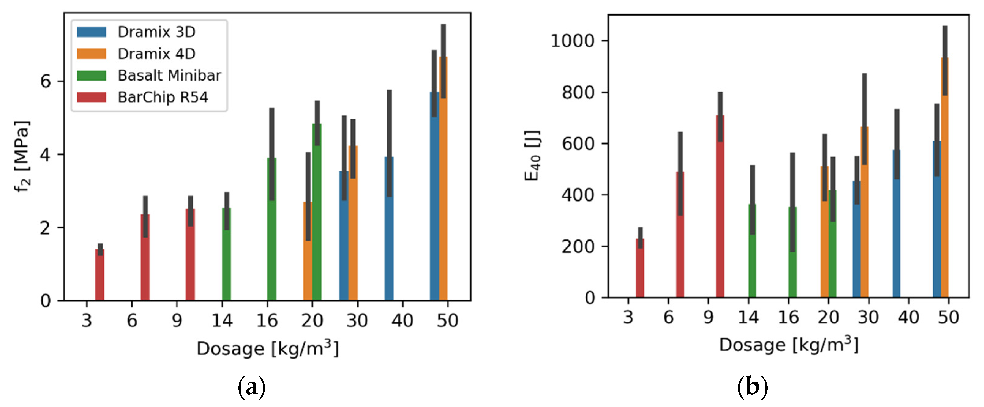
5.1. Experimental Results

In Table 7, selected results from the experimental campaign are presented. This includes compressive cube strength f c and residual strength at a maximum vertical deflection of 2.0 ( f r 2 ) and 3.0 ( f r 3 ) mm, respectively, for the individual samples as well as the mean value of the test series. The energy absorption for the panels at a vertical deflection of 40 mm ( E 40 ) is also presented. The complete results from the experimental campaign are reported by Sjölander et al. [53].
In Figure 6, the residual flexural strength at 2.0 mm f re , 2 and the energy absorption at 40 mm deflection E 40 are plotted for all fibre types and dosages. The black vertical line indicates the range of values for each test series. Here, it can be seen that synthetic fibres achieve the lowest f re , 2 regardless of dosage. However, for the energy absorption at large deformations, i.e., 40 mm, synthetic fibres with a dosage of 9 kg/m3 outperform almost all the other fibre types. This clearly indicates that the tested type of synthetic fibre is more efficient at larger displacements. For the basalt fibre, the opposite can be seen. It is efficient at small displacements, and while 14 and 16 kg/m3 of MiniBar are comparable to 30 and 40 kg/m3 of Dramix 3D with respect to f re , 2 , the Dramix 3D performs better at larger displacements, i.e., has a higher energy absorption at 40 mm deflection. Thus, for the tested fibres, synthetic fibres perform better at larger displacements, basalt at small displacements, and steel performs well at both small and large displacements. Despite this, this does not necessarily mean that fibres of a certain material are unsuitable for small or large displacements. The geometry of the fibre plays a crucial part in the post-cracking performance of fibre-reinforced shotcrete. The major energy consumption mechanism during failure is debonding of the fibre, followed by deformation and the resistance due to friction, while the fibre is being pulled-out from the concrete matrix, and thus, the shape and potential presence of end-hooks are crucial. How the efficiency of the end-hooks affects the results is seen by comparing the results from Dramix 3D and 4D. Theses fibres have similar mechanical properties, see Table 5, but the Dramix 4D fibre has a different design of the end-hook, as seen in Figure 4, which affects its pull-out capacity from the concrete matrix as can be seen in the results in Figure 6. Both basalt and synthetic fibres are available with different lengths and geometries, which could be more effective at smaller or larger displacement compared to the fibres tested here. Thus, the effectiveness of the fibre depends on the characteristics of the material but also on the geometry of the fibre, which must be considered when selecting a suitable fibre for the design situation.

5.2. Structural Performance

In Table 8, a suitable dosage and the calculated global warming potential (GWP) for each fibre type is presented for the design methods presented in Section 4. For the tested beams, the mean flexural strength was 7.3 MPa. This, in combination with the ratios in Table 1, was used to calculate the limits for the toughness performance level f re TPL . The results marked with an asterisk (*) in Table 8 indicate that the test results were more than 50% higher compared to the requirements. Thus, these dosages could be reduced significantly and still fulfil the required residual strength or energy absorption.
Starting with the results from the design case in good rock, i.e., for Q = 20, rock class B and TPL I, the limits of f re TPL are 1.8 and 0.7 MPa for vertical deflections of 0.5 and 2.0 mm, respectively. It can be noted that f re TPL is significantly lower compared to the required residual strength based on Australian f re AUS and Swedish guidelines f re SWE , which was 3.0 and 4.0 MPa, respectively. Naturally, this results in a lower required dosage of fibres. However, the required dosage of fibres to fulfil f re TPL is not clear from the results in Table 8 since the lowest tested dosages had a residual strength significantly higher than 1.8 MPa. Thus, the requirements of f re TPL can be fulfilled with significantly lower dosages than tested here. A similar scenario can be seen for the design based on the Q-method. Here, a round panel should be able to absorb 200 J at 40 mm vertical deformation. The result shows that a panel with 3 kg/m3 of BarChip 54, which had a mean energy absorption of 236 J, is sufficient to fulfil the requirements. However, the result for the other fibre types yields a mean energy absorption of around 500 J. This dosage could therefore be significantly reduced and still fulfil the requirements with respect to the design based on the Q-method.
From these results, it is clear that a large discrepancy exists between a design based on the Q- and TPL-method on one hand and the national guidelines from Sweden and Australia on the other hand. Naturally, this results in significantly lower dosages of fibres while designing the rock support based on the Q- and TPL-methods. How this effects the post-cracking performance is illustrated in Figure 7, in which the residual flexural strength at 2 mm deflection f re , 2 is plotted together with the energy absorption at 40 mm deflection E 40 for the dosages required to fulfill f re SWE and f re AUS . The horizontal line indicates the requirements for f re TPL and E RDP , respectively. As reported in [54], in situ measurements of stresses and failures of shotcrete linings are rare, and the load acting in the shotcrete is complex to analyze. To determine a suitable residual capacity for the shotcrete lining and to point out which of the presented design methodologies that is most suitable is therefore difficult. For a tunnel excavated in a rock mass of good quality, it could be argued that the tunnel should be stable and the loading on the rock support should therefore be low. Hence, a shotcrete lining with a low residual capacity could be used. On the other hand, load-independent stresses, caused by, e.g., drying shrinkage and thermal expansion, could lead to severe cracking already in the construction phase as shown by, e.g., Ansell [55] and Sjölander and Ansell [56]. Hence, adding more fibres to increase the ductility and, possibly, to reduce the crack widths could be preferable.
For the second design scenario, i.e., when Q = 1.5, which corresponds to when rock class is D and TPL III, the limits of f re TPL are 4.9 and 3.4 MPa for vertical deflections of 0.5 and 2.0 mm, respectively. Here, the required dosage of fibres to fulfil the requirements of f re TPL is among the highest between the four design methods. Hence, a design based on f re TPL yields a high a residual capacity for the shotcrete lining. The structural requirements for the shotcrete based on Australian standard are now based on energy absorption instead of residual flexural strength. For the studied case, this actually results in lower required dosages of fibre while using Dramix 4D and MiniBar. Moreover, 6 kg/m3 synthetic fibres was sufficient to fulfil the requirements in the case with lower quality rock, i.e., for rock class D but not for rock class B. One possible explanation to this is that the fibres could be used more efficiently when larger displacements are allowed. Still, the structural requirements based on the Q-method result in low dosages of fibres compared to the other methods. For the tested dosages of fibres presented in Table 8, the energy absorption of a round panel at 40 mm deflection is more than 50% higher compared to the requirements based on the Q-method. The recommended residual strength of the shotcrete, and thereby the dosage of fibres, according to the Swedish guidelines is unaffected by the rock class. This recommendation leads to the highest dosages of fibres for most of the cases. At the same time, all studied design cases are recommendations and not governing rules for the design.

5.3. Environmental Performance

Several interesting things can be noted regarding the fibres’ influences on the environmental impact. First, using a more efficient fibre will significantly reduce the climate impact from the construction. For a design based on Swedish guidelines, the amount of steel fibres could be reduced from 50 to 30 kg/m3 if a more efficient fibre was used, here exemplified by using Dramix 4D instead of Dramix 3D. This alone results in an approximate reduction of CO2 emissions from the fibres with 40%. Moreover, the CO2 emissions from basalt MiniBar and steel Dramix 3D are for the required dosages for most of the comparable design cases. However, the synthetic fibre BarChip shows the largest potential in lowering the CO2 emissions from production. As exemplified with the Australian design case for Q = 1.5, a total of 6 kg/m3 of BarChip 54 fibres was needed to fulfil the requirements. This resulted in a total of 12 kg of CO2 emissions. Compared to the second-best alternative with respect to GWP, Dramix 4D, CO2 emissions could be reduced with around 33% with the BarChip fibre. However, several other environmental indicators also exist and should be evaluated alongside the GWP. Moreover, it was shown by Anand [57] that a significant difference could exist between different fibre manufacturers of the same material, which should be accounted for when the most suitable fibres are determined. In Figure 8, the correlation between the mean energy absorption at 40 mm vertical deflection measured on a round determinate panel and the global warming potential (GWP) is plotted for all the tested fibre types and dosages. This shows some interesting trends. First, the steel fibres Dramix 3D and 4D show a more or less linear relationship between energy absorption and GWP for the tested dosages. For the BarChip fibres, there is a significantly larger improvement in energy absorption when the fibre dosage changes from 3 to 6 kg/m3 compared to the difference while changing from 6 to 9 kg/m3. There is only a small and almost negligible increase in energy absorption for basalt fibres when the dosage of fibres is increased from 14 to 20 kg/m3. This could indicate that fibres are less effective and will increase the energy absorption at a lower rate when the volume fraction of fibres in the shotcrete increases. The maximum dosage of steel fibres corresponds to a volume fraction of 0.6%, while the maximum dosages of synthetic and basalt fibres correspond to a volume fraction close to 1%.

6. Conclusions

The design of rock support is a complex task which involves many uncertainties. This has led to the development of different empirical approaches. In this paper, a review of the Q, TPL and RMR methods, with a particular focus on the requirements put on shotcrete thickness and structural capacity, has been presented. These methods were developed to assist the designer and to estimate preliminary support. The intention was not to create a design system. Nevertheless, due to the complexity involved in the design, these methods are sometimes used for the design. It has been clarified that the required shotcrete thickness, energy absorption and residual flexural strength are strictly based on empirical knowledge, and no theoretical background to these suggestions exists. In some countries, empirical recommendations and guidelines have been developed that set recommended requirements on the shotcrete regarding energy absorption or residual flexural strength. In this paper, recommendations from Sweden and Australia were presented. Results from an experimental campaign with different dosages of steel, basalt and synthetic fibres were presented. This campaign tested compressive strength, residual flexural strength and energy absorption according to standards [35,37,46].
The results from the experiments were put into context with a case study in which the required dosage of the different fibre types was selected based on four different design approaches. It should be clarified that the Q- and TPL-methods are intended to be used as tools for preliminary design, while national guidelines are recommendations and not a governing standard for the design. Still, such methods tend to form a foundation for the design process. The case study outcome highlighted significant differences between the required structural performance of shotcrete based on the Q and TPL methods and the Swedish and Australian guidelines. For rock support in a rock mass of good quality, here exemplified with Q = 20 and rock class B, it was shown that a stringent use of the Q and TPL design recommendations yields a low dosage of fibres. Compared to suggested fibre dosages based on Swedish or Australian guidelines, this results in a shotcrete lining with much lower ductility. On the one hand, it could be argued that the deformation of a rock mass of good quality should be low, resulting in low stresses on the shotcrete lining. Therefore, shotcrete with high ductility is not needed, and a design bases on the Q or TPL may be sufficient. On the other hand, load-independent stresses could lead to severe cracking of the shotcrete before the tunnel is in service. Hence, a shotcrete lining with low dosages of fibres, as recommended by the Q- and TPL-method, will result in a significant theoretical reduction in structural capacity. Thus, such a design may yield a rock support with low, or even insufficient, structural capacity in the cracked state. Determining the optimal structural requirements for fibre-reinforced shotcrete is a complex task. One way forward is through numerical simulations, e.g., the finite element method. However, measurements of in situ stresses in the shotcrete lining are rare. Thus, the combined complexity of determining the load and load distribution between rock and shotcrete makes it difficult to assess the quality of such numerical models. Moreover, results from numerical simulations of in situ stress states should be interpreted carefully since many of the necessary input variables include uncertainties.
A lining with a low dosage of fibres is the best alternative from an environmental perspective, while a lining with a large dosage of fibres will have the largest margin of safety. However, the results in this paper have shown that it is quite likely that the design of the shotcrete lining could be optimized to reduce the use of materials and to lower the emissions of greenhouse gases. To reach this, the understanding of the interaction between the rock mass and the support system, and especially the loading on the shotcrete, must be increased. One way to reach this is to conduct more in situ measurements of the shotcrete to understand the stress distribution better.
The environmental impact of the tunnel’s construction was evaluated based on EPDs. Here, the global warming potential (GWP) for each design alternative was evaluated, and based on this, it was clear that using more efficient fibres of the same material could significantly decrease the GPW from the tunnel’s construction. Furthermore, the synthetic fibre BarChip showed the most considerable potential in lowering the GWP of fibre-reinforced shotcrete. Finally, the environmental impact study in this paper only considered the required dosage of fibres to achieve a specific structural capacity for the shotcrete. For the design of a tunnel, several other aspects must also be investigated. Tunnels are often designed for a technical lifespan of 100 years or more. Thus, fibres must be durable over a long period and not lose their structural capacity over time due to the effects of creep or relaxation. To achieve a sustainable design, owners and designers of tunnels must, therefore, carefully define the structural requirements the shotcrete must fulfil and then evaluate what type of fibre is most suitable with respect to the structural capacity, durability, maintenance and environmental impact. The potential practical impact of differences in the amount of fibre rebound from different types of fibres could also influence the GWP and should be investigated.

Author Contributions

Conceptualization, A.S., A.A. and E.N.; Methodology, A.S., A.A. and E.N.; Investigation, A.S.; Resources, E.N.; Data Curation, A.S.; Writing—Original Draft Preparation, A.S.; Writing—Review and Editing, A.A. and E.N.; Visualization, A.S.; Funding Acquisition, A.A. All authors have read and agreed to the published version of the manuscript.

Funding

This research was funded by the Swedish Transport Administration (Trafikverket).

Data Availability Statement

Complete results from experimental testing are provided: A. Sjölander, E. Nordström, A. Ansell. Data from structural testing of sprayed and cast shotcrete reinforced with fibres of steel, basalt and synthetic material. Mendeley Data, V1, https://data.mendeley.com/datasets/d7n5mvb2sg, accessed on 1 December 2022.

Acknowledgments

The authors would like to thank Mattias Roslin and Per Vedin for their support to the project. The authors would also like to thank the personnel at Vattenfall R&D for performing the testing.

Conflicts of Interest

The authors declare no conflict of interest.

References

  1. Johansson, F.; Roslin, M.; Josefosson, J. Evaluation of Glass-Fibre Bolt as Permanent Rock Support; Technical report; KTH Royal Institute of Technology: Stockholm, Sweden, 2020. (In Swedish) [Google Scholar]
  2. Bjureland, W.; Johansson, F.; Sjölander, A.; Spross, J.; Larsson, S. Probability distributions of shotcrete parameters for reliability-based analyses of rock tunnel support. Tunn. Undergr. Space Technol. 2019, 87, 15–26. [Google Scholar] [CrossRef]
  3. Wetlesen, T.; Krutrök, B. Measurment of shotcrete thickness in tunnel with Bever 3D laser scanner operated from robot. In Proceedings of the 7th International Symposium on Sprayed Concrete, Sandefjord, Norway, 16–19 June 2014. [Google Scholar]
  4. Solla, M.; Pérez-Gracia, V.; Fontul, S. A Review of GPR Application on Transport Infrastructures: Troubleshooting and Best Practices. Remote Sens. 2021, 13, 672. [Google Scholar] [CrossRef]
  5. Belloni, V.; Sjölander, A.; Ravanelli, R.; Crespi, M.; Nascetti, A. Tack project: Tunnel and bridge automatic crack monitoring using deep learning and photogrammetry. ISPRS—Int. Arch. Photogramm. Remote. Sens. Spat. Inf. Sci. 2020, XLIII-B4-2, 741–745. [Google Scholar] [CrossRef]
  6. Insa-Iglesias, M.; Jenkins, M.D.; Morison, G. 3D visual inspection system framework for structural condition monitoring and analysis. Autom. Constr. 2021, 128, 103755. [Google Scholar] [CrossRef]
  7. Sjölander, A. Structural Behaviour of Shotcrete in Hard Rock Tunnels. Ph.D. Thesis, KTH Royal Institute of Technology, Stockholm, Sweden, 2020. [Google Scholar]
  8. Myren, S.; Bjøntegard, Ø.; Hagelia, P. The ban of polymer fibre in FRS in Norwegian road tunnels. In Proceedings of the 8th International Symposium on Sprayed Concrete, Trondheim, Norway, 11–14 June 2018. [Google Scholar]
  9. Ansell, A. Dynamically Loaded Rock Reinforcement. Ph.D. Thesis, KTH Royal Institute of Technology, Stockholm, Sweden, 1999. [Google Scholar]
  10. Bryne, L.E. Time Dependent Material Properties of Shotcrete for Hard Rock Tunneling. Ph.D. Thesis, KTH Royal Institute of Technology, Stockholm, Sweden, 2014. [Google Scholar]
  11. Holmgren, J. Punch-Loaded Shotcrete Linings on Hard Rock; Technical report; Rock Engineering Research Foundation (BeFo): Stockholm, Sweden, 1979. [Google Scholar]
  12. Malmgren, L. Interaction between Shotcrete and Rock: Experimental and Numerical Study. Ph.D. Thesis, Luleå University of Technology, Luleå, Sweden, 2005. [Google Scholar]
  13. Nordström, E. Durability of sprayed concrete–Steel fibre corrosion in cracks. Ph.D. Thesis, Luleå University of Technology, Luleå, Sweden, 2005. [Google Scholar]
  14. Bernard, E. Design of fibre reinforced shotcrete linings with macro-synthetic fibres. In Proceedings of the 11th Shotcrete for Underground Support, Davos, Switzerland, 7–10 June 2009. [Google Scholar]
  15. Monaldo, E.; Nerilli, F.; Vairo, G. Basal-based fiber-reinforced materials and structural applications in civil engineering. Compos. Struct. 2019, 214, 246–263. [Google Scholar] [CrossRef]
  16. Mohaghegh, A. Structural Performance of High-Performance Macro Basalt Fibre Concrete: Flexural, shear, Punching Shear and Fire Spalling. Ph.D. Thesis, KTH Royal Institute of Technology, Stockholm, Sweden, 2018. [Google Scholar]
  17. Afroz, M.; Patnaikuni, I.; Venkatesan, S. Chemical durability and performance of modified basalt fiber in concrete medium. Constr. Build. Mater. 2017, 154, 191–203. [Google Scholar] [CrossRef]
  18. Fiore, V.; Scalici, T.; Di Bella, G.; Valenza, A. A review on basalt fibre and its composites. Compos. Part B Eng. 2015, 74, 74–94. [Google Scholar] [CrossRef]
  19. EN 1997-1; Eurocode 7: Geotechnical Design Part 1: General Rules. Technical standard. EU: Brussels, Belgium, 2004.
  20. Bieniawski, Z. Engineering classification of jointed rock masses. Civ. Eng. S. Afr. 1973, 15, 333–343. [Google Scholar]
  21. Barton, N.; Lien, R.; Lunde, J. Engineering classification of rock masses for the design of tunnel support. Rock Mech. Rock Eng. 1974, 6, 189–236. [Google Scholar] [CrossRef]
  22. Terzaghi, K. Rock defects and loads on tunnel supports. In Rock Tunneling with Steel Supports; Proctor, R., White, T., Eds.; Publication 418–Soil mechanics series 25; Harvard University: Boston, MA, USA, 1946. [Google Scholar]
  23. Grimstad, E.; Barton, N. Updating the Q-System for NMT; Norwegian Geotechnical Institute: Oslo, Norway, 1993. [Google Scholar]
  24. Grimstad, E.; Kankes, K.; Bhasin, R.; Magnussen, A.W.; Kaynia, A. Rock mass quality Q used in designing reinforced ribs of sprayed concrete and energy absorption. In Proceedings of the 4th International Symposium on Sprayed Concrete, Davos, Switzerland, 22–26 September 2002. [Google Scholar]
  25. NGI. Using the Q-System: Rock Mass Classification and Support Design; TDOK2016:0231; NGI: Oslo, Norway, 2016. [Google Scholar]
  26. EFNARC. European Specification for Sprayed Concrete; Technical report; EFNARC: Surrey, UK, 1996. [Google Scholar]
  27. Bieniawski, Z.T. Rock mass classification in rock engineering. In Proceedings of the Symposium on Exploration for Rock Engineering, Cape Town, South Africa, 1–5 November 1976. [Google Scholar]
  28. Bieniawski, Z.T. The geomechanics classification in rock engineering applications. In Proceedings of the 4th International Congress on Rock Mechanics, Rotterdam, The Netherlands, 1 January 1979; Volume 2, pp. 41–48. [Google Scholar]
  29. Aksoy, C.O. Review of rock mass rating classification: Historical developments, applications, and restrictions. J. Min. Sci. 2008, 44, 51–63. [Google Scholar] [CrossRef]
  30. Singh, B.; Goel, R.K. Engineering Rock Mass Classification: Tunneling, Foundations and Landslides; Butterworth-Heinemann: Amsterdam, The Netherlands, 2011; pp. 45–62. ISBN 9780123858788. [Google Scholar] [CrossRef]
  31. Hudson, J.A. Rock Testing and Site Characterization; Pergamon: Amsterdam, The Netherlands, 1995; ISBN 9780080420660. [Google Scholar] [CrossRef]
  32. Papworth, F. Design guidelines for the use of fibre-reinforced shotcrete in ground support. Shotcrete Mag. 2002, 1, 16–21. [Google Scholar]
  33. Heere, R.; Morgan, D.R. Specification of shotcrete toughness. Shotcrete Magazine, Fall. 2003; 14–16. [Google Scholar]
  34. Trafikverket. Projektering av Bergkonstruktioner; Planning of Structures in Rock, Trafikverket: Borlänge, Sweden, 2015. (In Swedish) [Google Scholar]
  35. EN 14488-3; Testing Sprayed Concrete Part 3: Flexural Strengths (First, Peak and Residual) of Fibre Reinforced Concrete Beam Specimens. Technical Standard. EU: Brussels, Belgium, 2006.
  36. AuSS. Recommended Practice Shotcreting in Australia; Technical Report; Concrete Institute of Australia: Rhodes, Australia, 2010. [Google Scholar]
  37. ASTM C1550-19; Standard Test Method for Flexural Toughness of Fibre-Reinforced Concrete. Technical Standard. ASTM: West Conshohocken, PA, USA, 2019.
  38. Mao, D.; Bjorn, N.; Lu, M. Numerical analysis of rock fall at Hanekleiv road tunnel. Bull. Eng. Geol. Environ. 2012, 71, 783–790. [Google Scholar] [CrossRef]
  39. Morton, E.; Thompson, A.G.; Villaecusa, E.; Howard, D. Static testing of shotcrete. In Proceedings of the 13th Australian Tunnel Conference, Melbourne, Australia, 4–7 May 2008. [Google Scholar]
  40. Barrett, S.; McCreath, D. Shortcrete support design in blocky ground: Towards a deterministic approach. Tunn. Undergr. Space Technol. 1995, 10, 79–89. [Google Scholar] [CrossRef]
  41. Fernandez-Delgado, G.; Cording, E.J.; Mahar, J.W. Shotcrete: Structural Testing of Thin Liners; Technical report; University of Illinois: Washington, DC, USA, 1975. [Google Scholar]
  42. Holmgren, J. Bolt-anchored, steel-fibre-reinforced shotcrete linings. Tunn. Undergr. Space Technol. 1987, 2, 319–333. [Google Scholar] [CrossRef]
  43. Sjölander, A.; Hellgren, R.; Malm, R.; Ansell, A. Verification of failure mechanisms and design philosophy for a bolt-anchored and fibre-reinforced shotcrete lining. Eng. Fail. Anal. 2020, 116, 104741. [Google Scholar] [CrossRef]
  44. EN 14487-1; Sprayed Concrete Part 1: Definitions, Specifications and Conformity. Technical Standard. EU: Brussels, Belgium, 2005.
  45. Brodd, E.; Östlund, L. Environmental and Technical Evaluation of Cement Reduction and Test Methods for Fibre Reinforced Shotcrete in Tunnels. Master’s Science Thesis, KTH Royal Institute of Technology, Stockholm, Sweden, 2022. [Google Scholar]
  46. EN 12390-3; Testing Hardened Concrete Part 3: Compressive Strength of Test Specimens. Technical Standard. EU: Brussels, Belgium, 2019.
  47. EN 12390-1; Testing Hardened Concrete Part 1: Shape, Dimensions and Other Requirements for Specimens and Moulds. Technical Standard. EU: Brussels, Belgium, 2019.
  48. EPD. BarChip 48, BarChip 54, and BarChip 60 Macro Synthetic Fibres; Environmental Product Declaration, 2020; Available online: https://www.environdec.com/library/epd2054 (accessed on 29 March 2022).
  49. EPD. Dramix Steel Fibres for Concrete Reinforcement; Environmental Product Declaration, 2021; Available online: www.itb.pl (accessed on 29 March 2022).
  50. EPD. Reforcetech Basalt MiniBar; Environmental Product Declaration, 2022; Available online: https://www.epd-norge.no/stal-armering-aluminiumskonstruksjoner/basalt-minibars-tm-article3823-323.htmlTM%281%29.pdf (accessed on 29 March 2022).
  51. EN 14025; Environmental Labels and Declarations–Type III Environmental Declarations–Principles and Procedures. Technical Standard. EU: Brussels, Belgium, 2010.
  52. EN 15804; Sustainability of Construction Works–Environmental Product Declarations–Core Rules for the Product Category of Construction Products. Technical Standard. EU: Brussels, Belgium, 2010.
  53. Sjölander, A.; Ansell, A.; Nordström, E. Data from Structural Testing of Sprayed and Cast Shotcrete Reinforced with Fibres of Steel, Basalt and Synthetic Material. Mendeley Data, V1. 2022. Available online: https://data.mendeley.com/datasets/d7n5mvb2sg (accessed on 1 December 2022).
  54. Sjölander, A. Analyses of Shotcrete Stress States due to Varying Lining Thickness and Irregular Rock Surfaces. Ph.D. Thesis, KTH Royal Institute of Technology, Stockholm, Sweden, 2017. [Google Scholar]
  55. Ansell, A. Investigation of shrinkage cracking in shotcrete on tunnel drains. Tunn. Undergr. Space Technol. 2010, 25, 607–613. [Google Scholar] [CrossRef]
  56. Sjölander, A.; Ansell, A. In-Situ and Laboratory Investigation on Leaching and Effects of Early Curing of Shotcrete. Nord. Concr. Res. 2019, 61, 23–37. [Google Scholar] [CrossRef] [Green Version]
  57. Anand, S. Evaluation of Environmental and Technical Performance of Alternate Fibres for Shotcrete in Tunnels. Master’s Thesis, KTH Royal Institute of Technology, Stockholm, Sweden, 2022. [Google Scholar]
Figure 1. The Q-system for design of rock support; from Grimstad et al. [24].
Fibers 11 00020 g001
Figure 2. Flow chart for calculation of RMR value; redrawn from [31].
Fibers 11 00020 g002
Figure 3. Examples of failure modes showing shear failure for a case with good bond strength (left) and flexural failure for a case with low bond strength (right).
Fibers 11 00020 g003
Figure 4. Fibres used in the experimental campaign, from left to right; Dramix 3D, Dramix 4D, BarChip 54, MiniBar. Metric scale in lower part of the picture.
Fibers 11 00020 g004
Figure 5. Preparation of panels for testing, casting (a), storages of specimen directly after casting (b), storage of specimens during hardening (c) and set-up for testing of round panel (d).
Fibers 11 00020 g005
Figure 6. Residual flexural strength at 2 mm vertical deflection (a) and energy absorption at 40 mm deflection (b) for different fibre types and dosages. Vertical lines indicate distribution in data.
Fibers 11 00020 g006
Figure 7. Residual flexural strength at 2 mm deflection for required dosages of fibres to fulfil f re SWE (a) and energy absorption at 40 mm deflection for required dosages to fulfil f re AUS (b) in rock with good quality, i.e., Q = 20. Horizontal line indicates the f re 2 limit for TPL design (a) and the E 40 limit for a design based on the Q-method (b).
Fibers 11 00020 g007
Figure 8. Correlation between the mean energy absorption at 40 mm vertical deflection for a round determinate panel and the global warming potential for all tested fibre types. Dosages are presented in kg/m3.
Fibers 11 00020 g008
Table 1. Correlation between rock mass rating and support; from [28].
RMRRock Support
81–100Occasional spot bolting.
61–80Local bolts in crown, c c = 2.5 m, h roof = 50 mm was needed
41–60Systematic bolts in crown and wall, c c = 1.5–2.0 m, h roof = 50–100 mm and h wall = 30 mm
21–40Systematic bolts in crown and wall, c c = 1.0–1.5 m, h roof = 100–150 mm and h wall = 100 mm
0–20Systematic bolts in crown and wall, c c = 1.0–1.5 m, h roof = 150–200 mm and h wall = 150 mm
c c = spacing between bolts; h roof = shotcrete thickness roof; h wall = shotcrete thickness wall.
Table 2. Correlation between rock class and energy absorption based on square (SQU) and round panels (RDP) as well as TPL and flexural residual strength; from [4,13,24].
Rock ClassTPL E SQU
(J)
E RDP
(J)
f re TPL  
(-)
f re TPL  
(MPa)
f re SWE  
(MPa)
f re AUS  
(MPa)
E RDP AUS  
(J)
A000003.5–4.03.0
B1>500>2000.1–0.250.4–1.03.5–4.03.0
C2>500>2000.25–0.471.0–1.93.5–4.0 400
D3>700>2800.47–0.671.9–2.73.5–4.0 400
E4>1000>4000.67–1.02.7–4.03.5–4.0 400
F4>1400>5600.67–1.0>4.03.5–4.0 400
Table 3. Overview of experimental campaign.
FibreMaterialDosage (kg/m3)Beams
(-)
Panels
(-)
Cubes
(-)
Dramix 3DSteel30/40/503/3/33/3/33/3/3
Dramix 4DSteel20/30/403/3/33/3/33/3/3
Basalt MinibarBasalt14/16/203/3/33/3/33/3/3
BarChip 54Synthetic3/6/93/3/33/3/33/3/3
Table 4. Shotcrete mix.
MaterialQuantityUnit
(-)
Cement500kg/m3
Water204kg/m3
w/c0.41-
Aggregate 0–2 mm489kg/m3
Aggregate 0–8 mm1141kg/m3
Release agent 1 1.6kg/m3
Plasticizer 2 5.0kg/m3
Air 34.5–5.1%
Slump 380–160mm
1 Sika Perfin 301. 2 Sika Visco-Crete 6730. 3 Given as a range for all samples.
Table 5. Mechanical properties and geometry of fibres.
FibreDensity
(kg/m3)
E
(GPa)
f u
(MPa)
l
(mm)
d
(mm)
l/d
(-)
Dramix 3D 78502001800350.565
Dramix 4D78502001600350.565
Basalt Minibar200042>1000430.761
BarChip 5490012640540.690
Table 6. Global warming potential to produce 1 kg of different fibres given as kg CO2 equivalent. Data from [48,49,50].
CO2 Eq. to Produce 1 kg of Fibre
IndicatorDramixBarChipMiniBar
Global Warming Potential (GWP)0.88 kg2.01 kg2.11 kg
Table 7. Compressive strength, residual strength and energy absorption for shotcrete with steel, synthetic and basalt fibres with various dosages.
CubesBeams EN 14488-3 (MPa)Panels (J)
FibreDosage
(kg/m3)
f c
(MPa)
f r 2 f r 2
Mean
f r 3 f r 3
Mean
E 40
Dramix 3D5057/63/645.1/5.2/6.85.74.9/5.1/6.45.5709/764/724
Dramix 3D4060/63/652.9/3.2/5.73.92.7/3.1/5.23.7592/597/792
Dramix 3D3056/61/632.8/2.8/5.03.52.4/2.7/4.53.2472/516/564
Dramix 4D5057/57/595.6/6.9/7.56.74.8/5.0/8.16.7737/957/979
Dramix 4D3058/59/623.4/4.4/4.94.23.5/4.4/4.54.2525 */825/927
Dramix 4D2059/61/611.7/2.4/4.02.71.7/2.3/3.72.7577/583/653
Basalt Minibar2058/62/644.3/4.8/5.44.84.0/4.9/5.34.7475/536/557
Basalt Minibar1663/63/642.8/3.7/5.23.92.9/4.0/5.84.2379/511/644
Basalt Minibar1463/63/642.0/2.7/2.92.51.9/2.7/3.12.6362/503/514
BarChip 54955/55/572.1/2.6/2.72.52.3/2.9/3.12.8703/736/806
BarChip 54655/61/641.8/2.5/2.82.42.1/2.9/3.22.7558/610/662
BarChip 54349/51/541.3/1.4/1.51.41.4/1.5/1.61.5202/233/272
* 40 mm deflection was not met. Energy level from 35 mm.
Table 8. Suitable dosage of fibres and GWP for required fibre dose for different design cases, Q-values and rock class (RC).
Dramix 3DDramix 4DMiniBarBarChip
DesignQ
(-)
RC
(-)
Dosage
(kg/m3)
GWP
(kg CO2)
Dosage
(kg/m3)
GWP
(kg CO2)
Dosage
(kg/m3)
GWP
(kg CO2)
Dosage
(kg/m3)
GWP
(kg CO2)
E RDP —200 J20B30 *2620 * 1814 * 303 6
f re TPL   —TPL I20B30 *2620 * 1814 * 306 *12
f re AUS —3.0 MPa20B302630 2616 34--
f re SWE —4.0 MPa20B504430 262042--
E RDP —280 J1.5D30 *2620 *1814 *306 *12
f re TPL   —TPL III1.5D50445044----
E RDP AUS —400 J1.5D302620 1814 30612
f re SWE —4.0 MPa1.5D504430 262042--
* Energy absorption or residual strength is 50% higher than requirement. - No test result met the requirements.
Disclaimer/Publisher’s Note: The statements, opinions and data contained in all publications are solely those of the individual author(s) and contributor(s) and not of MDPI and/or the editor(s). MDPI and/or the editor(s) disclaim responsibility for any injury to people or property resulting from any ideas, methods, instructions or products referred to in the content.

