Abstract
Electrospun fibrous scaffolds made from polymers such as polycaprolactone (PCL) have been used in drug delivery and tissue engineering for their viscoelasticity, biocompatibility, biodegradability, and tunability. Hydrophobicity and the prolonged degradation of PCL causes inhibition of the natural tissue-remodeling processes. Poliglecaprone (PGC), which consists of PCL and Poly (glycolic acid) (PGA), has better mechanical properties and a shorter degradation time compared to PCL. A blend between PCL and PGC called PPG can give enhanced shared properties for biomedical applications. In this study, we fabricated a blend of PCL and PGC nanofibrous scaffold (PPG) at different ratios of PGC utilizing electrospinning. We studied the physicochemical and biological properties, such as morphology, crystallinity, surface wettability, degradation, surface functionalization, and cellular compatibility. All PPG scaffolds exhibited good uniformity in fiber morphology and improved mechanical properties. The surface wettability and degradation studies confirmed that increasing PGC in the PPG composites increased hydrophilicity and scaffold degradation respectively. Cell viability and cytotoxicity results showed that the scaffold with PGC was more viable and less toxic than the PCL-only scaffolds. PPG fibers were successfully coated with polydopamine (PDA) and collagen to improve degradation, biocompatibility, and bioactivity. The nanofibrous scaffolds synthesized in this study can be utilized for tissue engineering applications such as for regeneration of human articular cartilage regeneration and soft bones.
1. Introduction
The selection of a polymer for biomedical applications such as tissue engineering and drug delivery is quintessential for mimicking normal biological processes [1]. In tissue engineering, the polymer used to develop scaffolds must meet biocompatibility, wettability, and biodegradability standards in order to stimulate cell growth and proliferation [2,3]. The chemical makeup of the polymer and how it is processed into its final structure influences properties such as strength, flexibility, porosity, and nontoxicity [4].
Biodegradable polymers have been excessively exploited because of their ability to function effectively for a specific time before degrading [5,6]. Understanding the degradation behavior of biomaterials is important especially in designing a scaffold since it may alter its physicochemical characteristics, functionality, and even biological response [7,8]. Fast-degrading materials are known to accelerate wound closure in acute wounds whereas slow-degrading materials accelerate healing in diabetic or infected wounds [9]. The design of biodegradable polymers must not cause a sustained inflammatory response, should possess a degradation rate consistent with its function, must have appropriate mechanical properties, must have low cytotoxicity, and must retain appropriate permeability [10].
Among the several well-known biocompatible and biodegradable polymers, such as Poly(L-lactide) acid (PLLA), Poly (lactic-co-glycolic acid) (PLGA), and Poly(glycolic acid) PGA, Polycaprolactone (PCL), which is recognized as a safe material by the Food and Drug Administration (FDA) [11], PCL is one of the most regularly used synthetic polymers for long-term implant devices and drug delivery applications [12]. The in vivo and in vitro kinetics of PCL show that it exhibits slow degradation rates when compared to other biodegradable polymers which makes it a suitable biomaterial for applications where slow degradation is preferred [13]. The excellent mechanical properties, degradation ability, copolymerization ability with inorganic and organic compounds, and cost-effectiveness make PCL an attractive material for biomedical applications [14,15]. Some limitations of PCL, however, are that it is hydrophobic, lacks bioactivity, and has a slow degradation rate [16]. Hydrophobicity restricts the binding affinity of cells or bioactive chemicals, which in effect restricts its potential in tissue engineering applications [17]. Slow degradation also inhibits tissue-remodeling processes in some wound-healing applications [18]. Surface functionalization is therefore essential in modifying the chemical characteristics of the hydrophobic nature of PCL to increase its surface activity and bioactivity [19,20].
Blending PCL with other hydrophilic and bioactive polymers like chitosan, collagen, and gelatin, among others, can change the chemical compositions, molecular weights, and crystallinity of the PCL for the desired outcome [21,22,23].
Poliglecaprone (PGC), a synthetic copolymer consisting of both soft (epsilon-caprolactone) and hard (glycolide) segments is used for sutures and general surgical implants [24,25,26], and also for subcutaneous and subdermal tissue closure because of its ability to elicit minimal inflammatory response [27,28]. PGC is durable and has a swift degradation rate and high initial tensile strength [29].
A combination of PCL and PGC will result in shared properties to improve PCL scaffold limitations such as modifying its degradation rate for wider application use [18,30,31,32].
Electrospinning is a technique used to produce nanofibrous scaffolds using high voltage. Electrospun scaffolds are used in the fields of agriculture, tissue engineering, drug delivery, the pharmaceutical industry, wound care, and diagnostics. Electrospun fibrous scaffolds have physical properties similar to the natural 3D macromolecular network of the ECM [33,34]. Nelson et al. utilized the ECM-mimicking structure of electrospun scaffolds to develop a novel gel-based delivery system to analyze MCF-7 and MDA-MB-231 metastasis [35].
Another study shows that the electrospun fibers of PCL with porous, wrinkled, and grooved morphology were excellent fiber topography for the proliferation and attachment of keratinocytes and dermal fibroblasts [36].
More studies show that the degradation of the electrospun scaffold material influences structural integrity and cell viability. For instance, Lam et al. investigated the in vitro degradation of PCL scaffolds and PCL-based composites in phosphate-buffered saline (PBS) and in vivo degradation of PCL scaffolds in a rabbit model for 6 months. All samples recorded molecular weight loss after 6 months, with the maximum loss being 7% from PCL composite scaffolds and the 1% minimum loss from PCL scaffolds. Histological examination in the study revealed good biocompatibility with both materials [37]. Another recent study synthesized a copolymer of PCL and PGC which showed accelerated degradation. They also noted that by blending PCL and PGC, the advantageous properties of the two materials were combined, resulting in a material with improved tensile strength, modulus, and hydrophilicity, as compared to PCL only [18].
A study done by Zhang et al., involving an electrospun bi-layer scaffold made of gelatin, elastin, PCL, and PGC, using human aortic endothelial cells (HAECs) showed that the regenerated endothelium possessed typical functions just as in native endothelium [30]. Furthermore, Patel et al. designed an electrospun polymer blend of PGC and PCL coated with HuBiogelTM and a combination of a collagenous matrix obtained from human placenta enhanced hydrophilicity and biocompatibility (cell viability and cell attachment) [38].
Despite the significant advantages that the blend of PCL and PGC offers in the biomedical field, more needs to be done to explore their degradability and further use in clinical settings.
The goal of this study was to use electrospinning to create nanofibrous PCL-PGC (PPG) composite scaffolds with varied compositions of PGC, as well as to coat PPG samples with polydopamine (PDA) and collagen to increase degradability and promote biocompatibility (cell viability and cell attachment). The fabricated nanofibrous scaffolds of PPG in this study can be utilized for tissue engineering applications such as the regeneration of cartilages and soft bones.
2. Materials and Methods
2.1. Materials
PCL polymer (Mn, 80 kDa), Amano lipase from pseudomonas fluorescence (≥20,000 U/g), and sodium azide were obtained from Sigma-Aldrich (Milwaukee, WI, USA). Poliglecaprone (Ethicon Monocryl™), a monofilament synthetic absorbable surgical suture, was obtained from e-sutures.com (product number Y267H). Hexafluoro-2-propanol (HFIP) was purchased from Alfa Aesar (Ward Hill, MA, USA). Dulbecco’s phosphate-buffered saline (DPBS) and Dulbecco’s modified Eagle’s medium (DMEM) were obtained from Life Technologies (Grand Island, NY, USA). Alamar Blue and Lactate Dehydrogenase (LDH) assay kits were purchased from Thermofisher-Scientific (Waltham, MA, USA).
2.2. PCL/PGC Solution Preparation
The PCL pellets and the PGC suture were dissolved in HFIP to form a PPG solution with “P” representing PCL and “PG” representing PGC. PPG solutions were made using different amounts of the PGC (0, 20, 35, and 50) in percent while maintaining the PCL. So, a PPG-20 labeled sample means 20% of PGC with the PCL. Parafilm was placed on the mixing container to prevent evaporation of the solution. All solutions were magnetically stirred for several hours until completely homogenous solutions were obtained.
2.3. Electrospinning of PPG Nanofibers
The electrospinning setup utilized a high-voltage power supply (Model CZE100PN30, Spellman High Voltage Electronics Corporation, Hauppauge, NY, USA), a drum collector, and a syringe pump (Model 78-01001, Fisher Scientific, Pittsburgh, PA, USA) which holds the syringe containing the solution. The setup and procedure were adopted from an earlier experiment in our lab [39]. In brief, the aluminum foil utilized as the conducting surface for the collection of the nanofibrous scaffold was placed onto the rotating collector and secured down the collector with tape. A 10 mL syringe was filled with 6 mL of polymeric solution and connected with an 18-gauge-diameter hypodermic needle. A syringe pump set at a flow rate of 1 mL/h was used to feed the designated solution through the syringe tip placed 10 cm from the grounded rotating collector. A wire from a high-voltage source was then clipped to the tip of the syringe needle tip. The high-voltage power source was maintained at a voltage of 15 kV. The solution was spun in the direction of the grounded, revolving drum.
After all solutions were electrospun, the fibrous scaffolds produced were dried and later detached from the aluminum foil for further characterization. Sample composition details are shown in (Table 1) below.

Table 1.
PPG sample designation and concentration.
2.4. Surface Morphology Analysis
The surface morphology of the fiber samples was examined using Scanning Electron Microscopy (SEM) specifically, the Field Emission Scanning Microscope (Hitachi SU8000, Tokyo, Japan). Prior to imaging, lyophilized fiber samples were placed on carbon tape and then gold coated using a Cressington Sputter Coater for 45 s to create a surface that is electrically conductive. Once coated, they were then placed into the chamber of the Field Emission Scanning Microscope (Hitachi SU8000, Japan).
The fiber diameter and frequency distribution were determined using Image J from the SEM images captured. A total of 100 different fiber diameters were obtained from each image for the diameter estimation. The scaled measurement was made equivalent in image J to that on the SEM image. The diameter measurements were made by drawing a straight line across the diameter of the fiber. The fiber diameters were then graphed and averaged to accurately represent the overall fiber diameter for each fiber composition.
2.5. X-ray Diffraction Analysis
For this test, a glass slide was utilized for each sample of PPG. First, the slide was covered with scotch tape with a tiny rectangular section left uncovered in the center. In the center, the fiber was gently placed and cut to cover the entire area. Next, 2 drops of polyvinyl alcohol (PVA) were dropped over each of the PPG fibers and dried for 24 h. After the specified period, the slides were placed on the stage of the X-ray diffractometer (Bruker D8, Billerica, MA, USA). The position-sensitive detector was then used for the examination of crystallography. All experiments were performed at room temperature.
2.6. Contact Angle Measurement
The sessile drop contact angle measurement of the PPG fibers was carried out using a KRUSS drop shape analyzer from Germany. A needle was attached to the syringe containing deionized (DI) water and secured in the vertical syringe holder. A “make drop” command from the software of the connected computer was issued to release a drop of DI water to the surface of the nanofiber. A picture of the drop with fiber sample was taken at two different time points (10, and 20 s). Three (3) samples for each fiber group were measured and averages were estimated to represent the water contact angle.
2.7. Mechanical Testing
Mechanical properties of the scaffolds were assessed using an Instron 5542 (North America Analytical and Measuring Instruments AGS-X series, Columbia, MD, USA) with a 500 N load set at a displacement rate of 2 mm/min. Prior to testing, rectangular tensile specimens with dimensions of 3 × 1 cm were prepared. The mechanical properties of the fibrous scaffolds were obtained and analyzed to determine Young’s Modulus (modulus of elasticity), and the ultimate tensile strength from the stress–strain curves produced from the data generated from the test. The slope of the linear portion of the stress–strain graph provided Young’s Modulus, which was determined using Hooke’s law. The ultimate tensile strength was obtained by determining the highest stress point the fibrous scaffold could bear without breaking.
2.8. In Vitro Degradation
For the in vitro degradation experiment, the fibers were cut into 3 cm × 1 cm rectangular sections and their respective weight measurements were taken before each fiber sample was placed inside a labeled conical tube. The conical tube was then filled with 10 mL of the Amano lipase degradation buffer which was prepared with 3 g of Amano lipase dissolved in 1000 mL of (1×) phosphate buffer solution (PBS) (pH 7.3). Next, 0.000048 g of sodium azide was added to the solution under a fume hood. The solution was shaken thoroughly for 1 min to ensure the mixture was homogenous. The specimens (n = 4) were each wrapped with parafilm to ensure the protection of the fibers as well as eliminate any possible evaporation or exposure of the solution to the conditions in which the tubes were placed. The nanofibrous scaffolds were exposed to the phosphate buffer solution for up to 4 weeks. The samples were kept in a water bath shaker maintained at a constant temperature of 37 °C. After each specified time interval, samples were removed from the degradation medium and washed thoroughly with DI water. The specimens were left at room temperature and weighed prior to being analyzed for mass loss percent, surface characterization, crystallography, and mechanical tensile testing. Samples were collected initially after an interval of 24 h; however, the remaining samples were collected once a week.
2.9. Surface Modification
For surface modification of the PPG samples, each fiber was cut into 1 cm × 1 cm dimensions. There was a total of 16 test samples, with 4 samples cut for each test day. Each sample was measured on a scale, sterilized with ethanol, and placed into a well plate labeled based on the fiber composition. To ensure attachment with collagen, the scaffold was immersed in a dopamine tris-HCL buffer solution (2 mg/mL, 10 mM Tris buffer at pH 8.5) prior to adding the collagen. Tris buffer was dissolved in 300 mL of distilled water. Hydrochloric acid was added to the Tris solution to adjust the pH level to 8.5. Once the pH level was reached, more distilled water was added to make 500 mL. Dopamine (1 g) was added to the 500 mL of the Tris solution to make the polydopamine (PDA) solution.
Prior to preparing the collagen solution, 1.8 mL of 2% acetic acid was first diluted in 100 mL of distilled water to form the acetic acid solution. Type I collagen was then dissolved in 1 mL of the acetic solution to form the collagen solution. The prepared collagen solution was diluted in PBS (10×) buffer 6 times, and the pH was adjusted using 0.1 mmol/L NaOH on ice. After all solutions were made, the scaffolds were immersed in the dopamine solution and then the collagen solution was added for 30 min at 37 °C. The fibrous scaffolds were then rinsed with deionized water twice and left to dry for 24 h. SEM imaging was used to confirm the presence of PDA and collagen on the fibrous scaffolds.
2.10. Cell Attachment, Viability, and Toxicity Analysis
NIH-3T3 mouse fibroblast cell lines were obtained from the American Tissue Type Culture Collection (ATCC 1658, Manassas, VA, USA), and the cells were cultured in a 75 cm2 culture flask and maintained in a tissue culture incubator at 37 °C and 5% CO2 atmosphere. After reaching about 80% confluency, the cells were detached and seeded to the PPG meshes. Before seeding the cells, the nanofiber sample pieces (n = 3), were circularly cut, and attached to a 24-well plate with Kwik-SilTM Surgical Silicone Adhesive (World Precision Instruments LLC, Sarasota, FL, USA). Each sample was sterilized using ethanol under UV. A 100 µL aliquot of medium mix containing about 50,000 cells was seeded on the different samples and grown in a humidified incubator (37 °C, 5% CO2) for days 1, 2, and 3.
For the cell toxicity testing, media was collected at each time point and stored. Stored media was used for the Lactate Dehydrogenase (LDH) assay following the protocol used in our previous papers [40,41]. The absorbance of the samples was measured at 490 nm and 680 nm by a microplate reader (CLARIOstar Plus, BMG LABTECH Inc., Cary, NC, USA). Cell cytotoxicity was further calculated using:
The cell viability of 3T3 cells was also examined using an Alamar Blue (AB) colorimetric assay. Prior to the examination, excess media on the fiber was removed and the well plate was washed twice with PBS. A 10% (v/v) AB reagent in the respective culture medium is added to the well plate and incubated for 4 h. Assay solutions were transferred after the 4 h to fresh well plates to measure fluorescence (530 nm excitation and 590 nm emission). Cell viability was calculated using the following equation:
3. Results and Discussion
3.1. Morphological Analysis of PPG Nanofibers
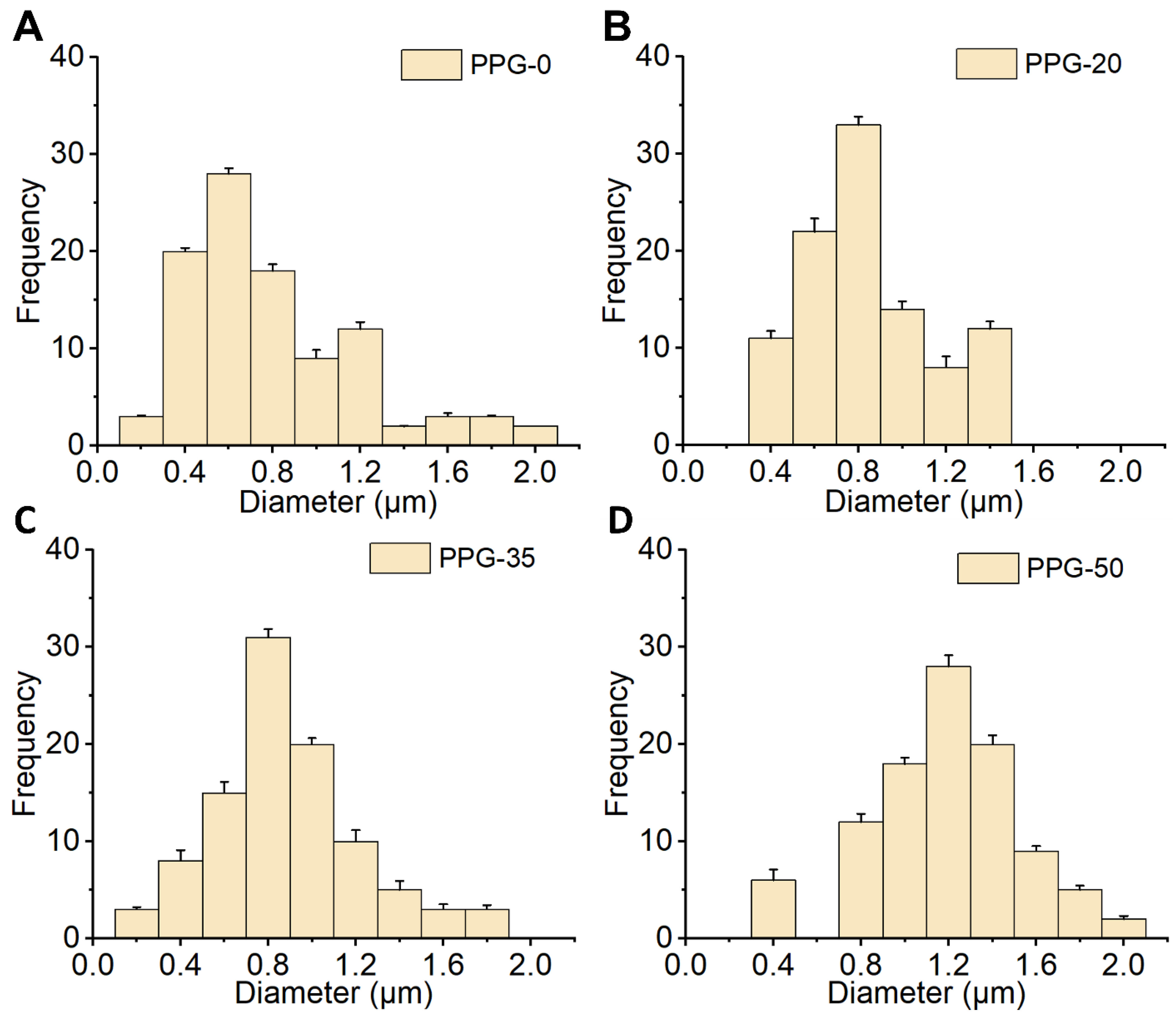
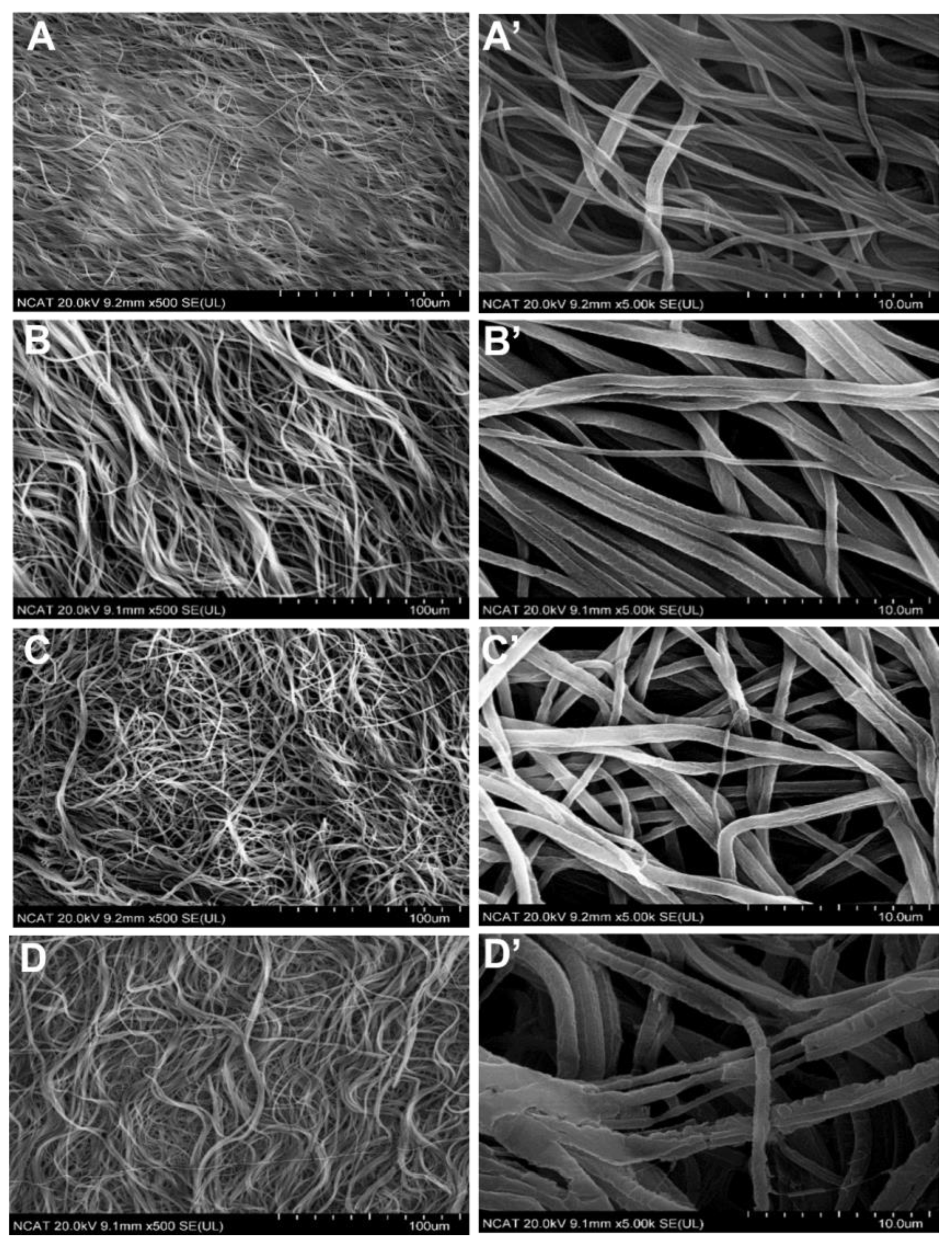
The composite scaffold was successfully prepared using electrospinning. The SEM micrograph of PPG at different concentrations is shown in Figure 1 and revealed randomly distributed fibers like the electrospun PGC and PCL blend fibers designed by Hao Yin et al. [42]. These relatively smooth fibers also had a linear cylindrical shape. This is necessary especially for fibroblast cells to take up this shape while proliferating. Some fibers showed an entanglement which is possible due to the interaction between the PCL-PGC molecules. With the increasing composition of PGC, there is a noticeable decrease in entanglements as observed in the SEM images. The average diameter of each fiber composition was estimated using Image J and was converted to pixels utilizing a scale bar. Figure 2 represents the average diameter range for each fiber group.
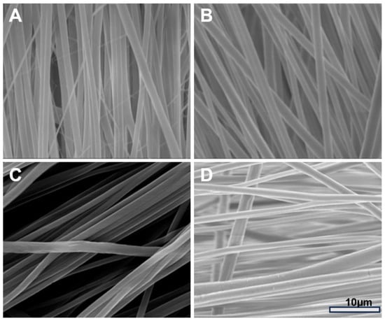
Figure 1.
Surface morphology of the PPG fibrous scaffold. (A–D) represent SEM images of as prepared electrospun fibers of PPG-0, PPG-20, PPG-35, and PPG-50, respectively.
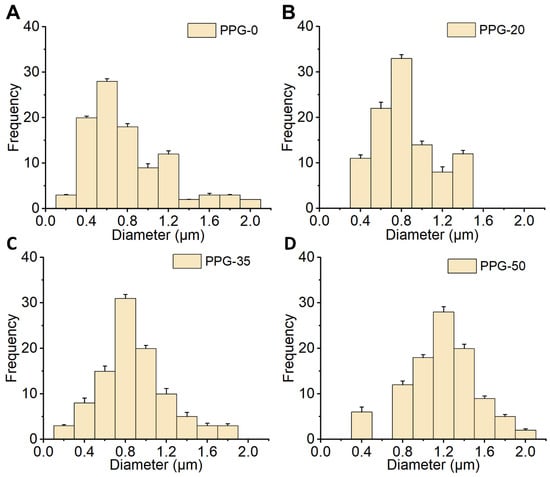
Figure 2.
Size distribution of PPG fibrous scaffold. Histograms, (A–D) represent the distribution of fiber diameters of the as-prepared PPG-0, 20, 35, and 50 samples, respectively.
The respective average diameter sizes of PPG-0, PPG-20, PPG-35, and PPG-50 fiber samples were 0.76 ± 0.2 µm, 0.81 ± 0.1 µm, 0.87 ± 0.4 µm, and 1.22 ± 0.2 µm. These results show that as the fiber increases in PGC content, diameter increases leading to thinner fibers with the thinnest being PPG-50 which is the fiber with 50% of PGC.
These diameters readings are like the respective non-woven fiber diameters reported by Zhang et al. [31].
3.2. X-ray Diffraction
The intensity and position of these peaks can be used to determine the degree of crystallinity in the sample. The XRD pattern for the PGC nanofiber scaffold showed two major peaks, 2θ = 21.7° and 2θ = 23.9°, which correspond to the (110) and (200) crystal planes of PCL, respectively (Figure 3). This indicates that there is no significant change in the chemical structure of PPG fiber even with the addition of PGC. Both PCL and PGC polymers are physically mixed in the fibers. However, the PCL peaks seem enhanced in the PPG-35 samples after its degradation. This indicates the degradation might have happened in the PGC potion and left the PCL crystalline phase enhanced.
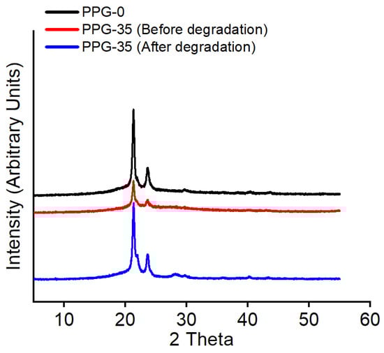
Figure 3.
Analysis of crystalline phases of PPG nanofiber scaffolds by comparing the XRD patterns of prepared fibers versus after degradation.
3.3. Contact Angle Analysis
The significance of the surface wettability was to estimate the hydrophilicity of the material, an important property of fibrous materials. An increase in hydrophilicity of fiber is decent for good cell proliferation. From the estimated contact angle measurements in Table 2 below, the average contact angles recorded were 137 ± 10.4, 54 ± 3.5, 47 ± 4.4, and 45 ± 6.1 representing PPG-0, PPG-20, PPG-35, and PPG-50, respectively. The increase in the contact angle of PPG-0 clearly indicates the hydrophobicity of the PCL-only nanofiber (PPG-0). The result also indicates that the steady increase in PGC with the PCL improves hydrophilicity since the angles are less than 90 °C [43]. In conclusion, all PPG samples are hydrophilic except the PGC-free nanofiber samples.
Table 2.
Summary of the contact angle measurements of the PPG nanofibers.
3.4. Mechanical Testing
Tensile strength is important for materials that are stretched or under tension to determine their mechanical performance. Fibers for tissue engineering utilization need good tensile strength to withstand various conditions. The tensile strength of PPG nanofibers was measured using Instron 5542. The nanofibers were loaded onto the machine and subjected to increasing tensile forces until they broke. The maximum force required to break the fibers was recorded as the ultimate tensile strength. Details of this estimation and other test run results are summarized in Table 3. The estimated tensile strength value for PPG-0, 20, 35, and 50 in order was 3.64 ± 0.07, 4.12 ± 0.05, 4.88 ± 0.05, and 6.11 ± 0.04 MPa; and Young’s modulus values were 14.6 ± 5.34, 23.9 ± 3.32, 28.4 ± 4.91, and 36.3 ± 9.76 MPa. The fiber with the greatest ultimate tensile strength was the fiber composed of an equal ratio of PCL and PGC (PPG-50). There was a drastic increase in the mechanical property of the nanofibers with the incremental addition of PGC although still elastic. PGC increased the mechanical integrity of the PCL fiber overall. A fiber consisting of PPG-50 would provide the ideal mechanical property necessary for a scaffold; thus, it has promising potential for further applications. It is worth noting that the tensile strength of nanofibers can vary depending on several factors, including the manufacturing process, the fiber diameter, and the testing conditions. Therefore, the specific tensile strength values obtained for PCL and PGC nanofibers may not be directly comparable to other studies or applications. Knowing the tensile capacity or the overall strength of the fiber prior to introducing it into the physiological environment prevents its easy damage. Materials stiffness or modulus is significantly considered for applications in tissue regeneration. It is predominantly preferred to have the material’s modulus near to that of the target tissue to circumvent potential stress-shielding effects and maintain sufficient mechanical support during in vitro and/or in vivo cell growth and tissue-remodeling processes [44]. The values generated from the mechanical testing as shown in Table 3, are assumed appropriate for structural applications like bone regeneration. These mechanical properties are comparable with other types of electrospun fibrous scaffolds utilized for the repair of rat calvarial defects, human articular cartilage, and bovine articular cartilage, as reported in the literature [14,18,44,45,46]. The Young’s modulus value for instance shows an extensive increase in hardness as PGC increases with the PCL. The ultimate tensile strength value also indicates that the highest PGC representing fiber has the maximum strength prior to breakage.
Table 3.
Mechanical properties of PPG meshes.
3.5. In Vitro Degradation
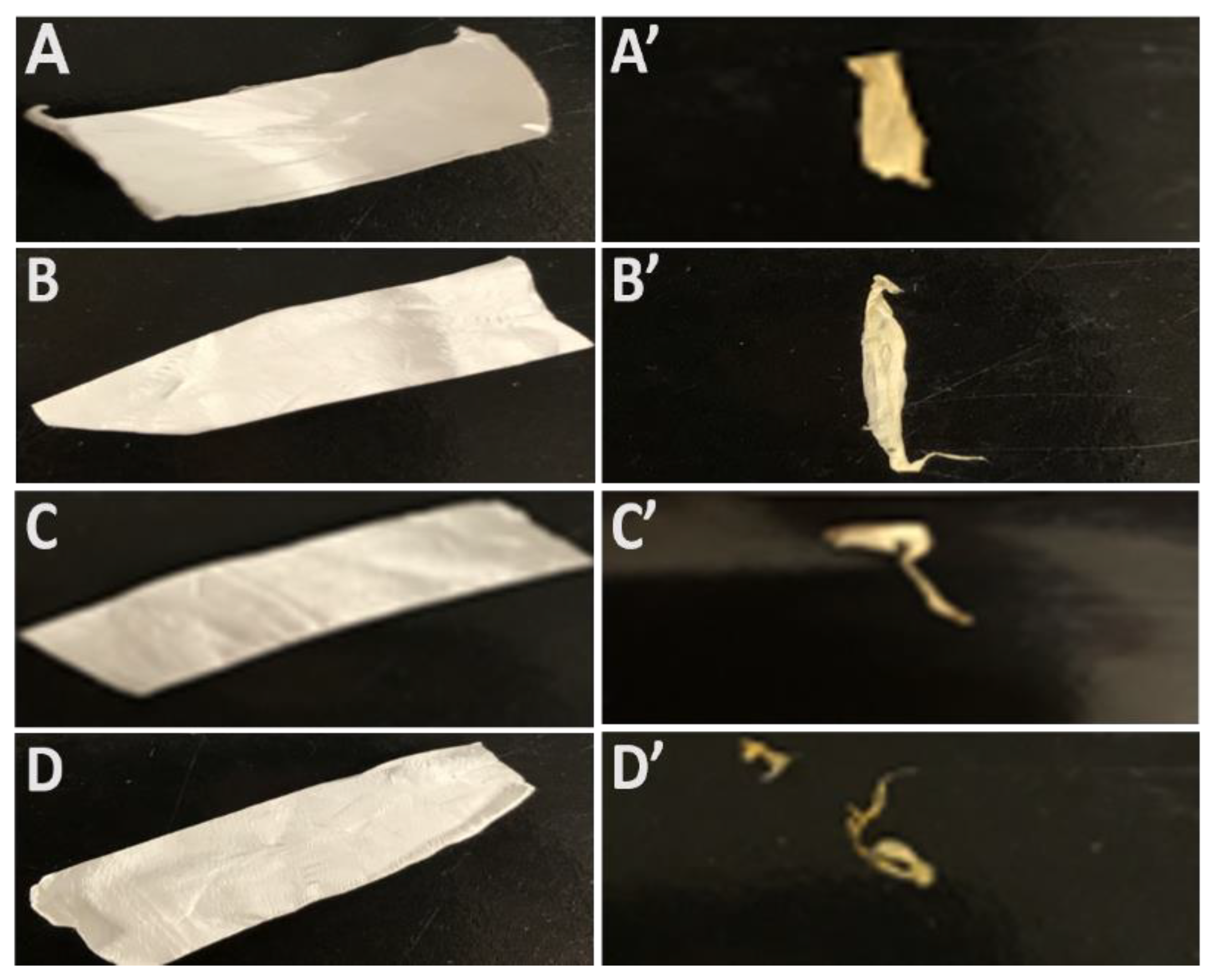
Figure 4 shows camera images of fibers before and after in vitro degradation analysis. The SEM images show that the fiber underwent degradation, resulting in a decreased fiber diameter and a change in fibrous structure due to the enzymatic degradation process. The surface morphology of the degraded fibers (Figure 5) showed fibers looking swollen compared to the as prepared in Figure 1. This change in morphology is due to the relaxation of the polymer after incubation with the medium.
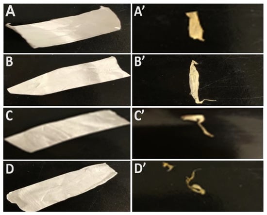
Figure 4.
Gross appearance of PPG nanofiber scaffolds in vitro degradation. Camera images of the scaffolds PPG-0 to PPG-50 before degradation (A–D) and after four weeks degradation (A’–D’).

Figure 5.
Surface morphology of the PPG scaffolds after in vitro degradation. SEM images of PPG-0 to PPG-50, at lower magnification (A–D), and higher magnification (A’–D’) after four weeks of degradation.
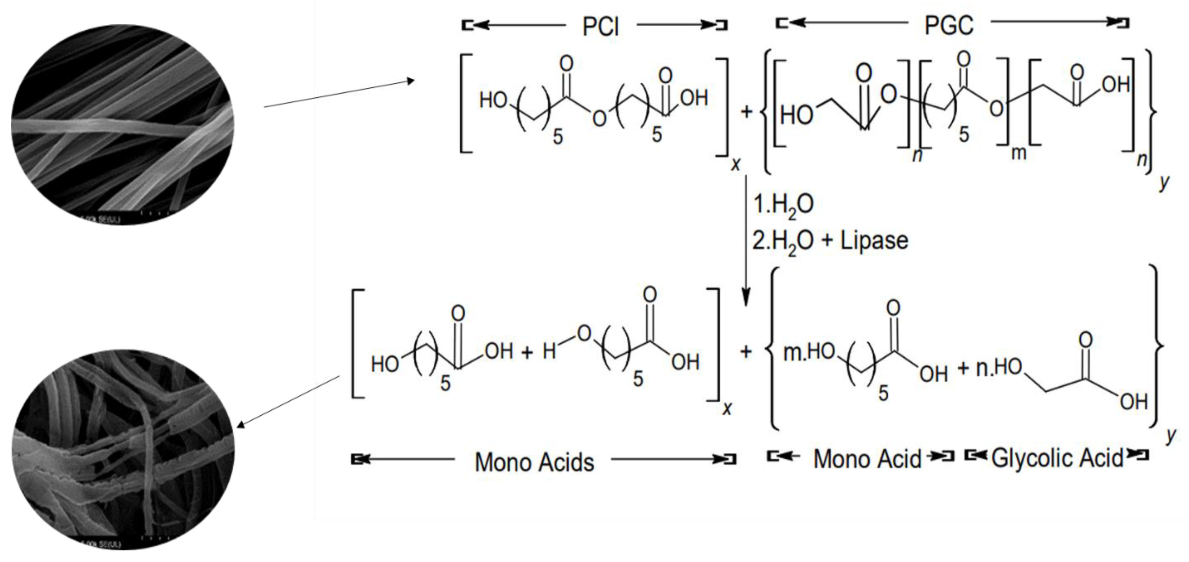
After one month, the fiber containing an equal composition of both polymers was almost completely degraded in the Amano lipase solution. Though PCL is known to degrade slowly, the initial degradation of PCL started out quickly in Amano lipase. The degradation mechanism of the combined PCL and PGC through hydrolysis is attributed to the cleavage of ester bonds, as illustrated in Figure 6. Additionally, the lipase enzyme, represented in the same figure, acts as a catalyzing enzyme to fragment the long polymer chain into smaller polymer fragments that are water soluble [47]. Overall, the degradation time can help to determine the suitable area of application.
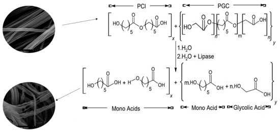
Figure 6.
The degradation mechanism of the PPG fibers. Top: chemical structures of as-prepared blend nanofibers of PCL and PGC (i.e., PPG fibers). Bottom: chemical structures of the possible molecular fragments after aqueous and enzymatic (i.e., lipase) hydrolysis.
3.6. Surface Modification
Dopamine-Collagen Coating of PPG Fiber
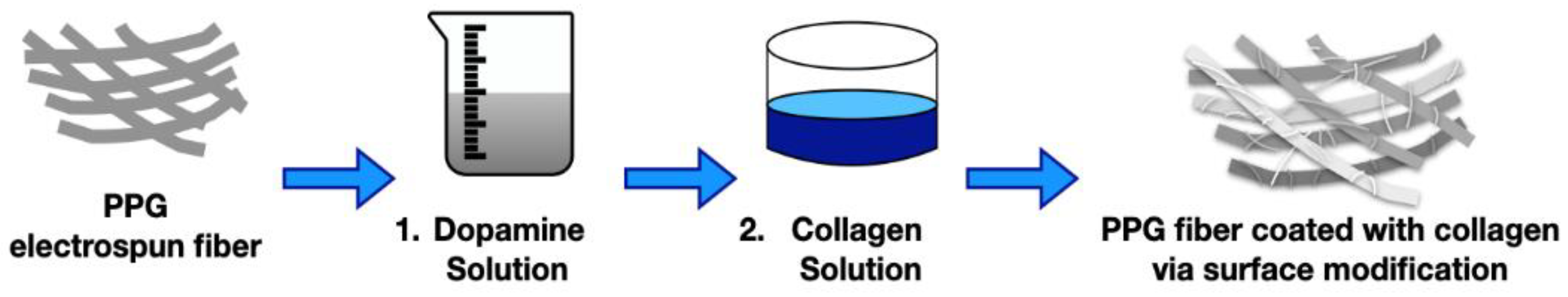
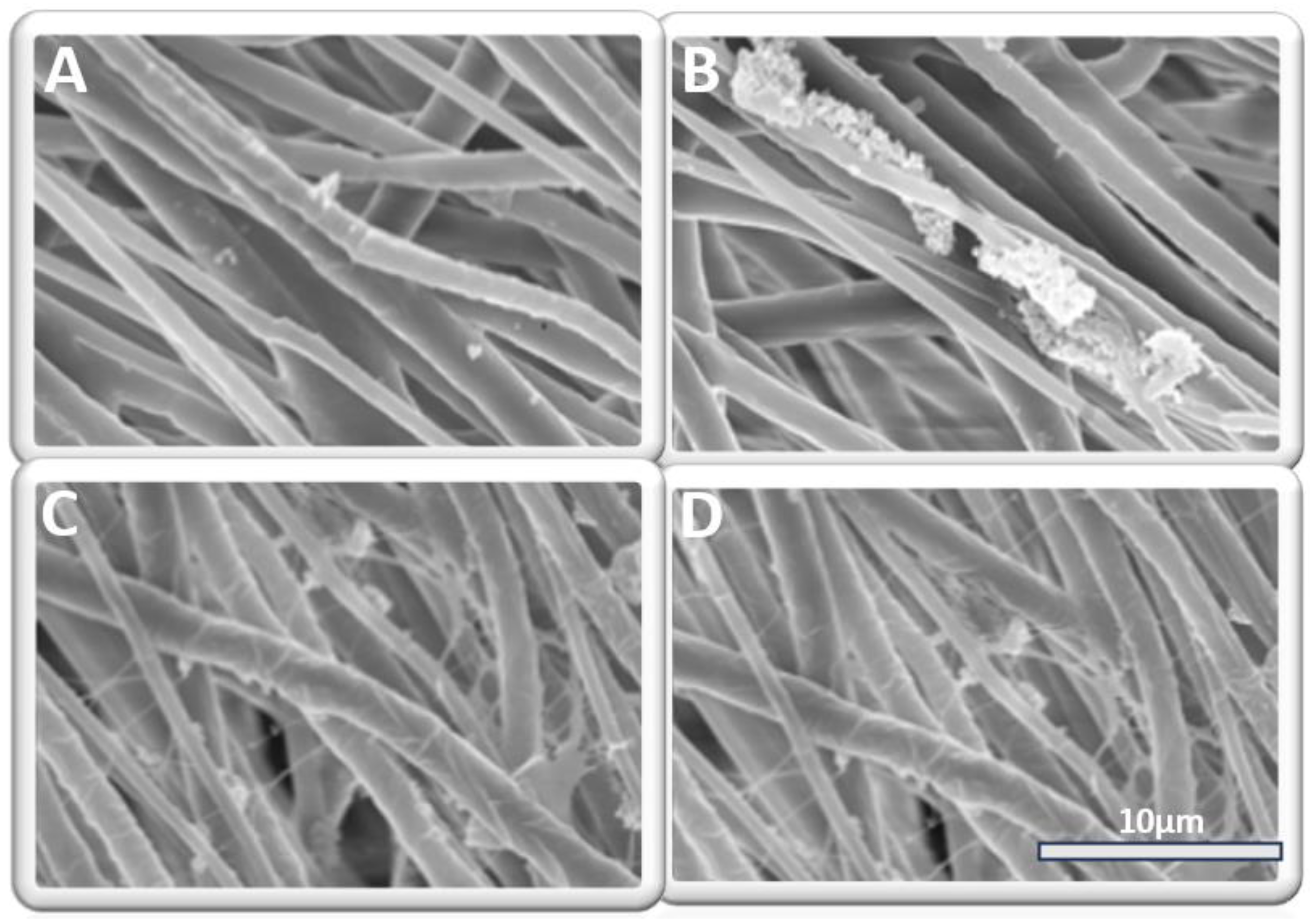
The schematic in Figure 7 highlights the dual process involved with the coating of polydopamine and collagen onto the PPG fiber. The successful coating of the fiber was confirmed via SEM imaging (Figure 8) in which the deposits and webbing on the fiber are prominent with the collagen. The fibers were prepared for morphological testing at two different phases.
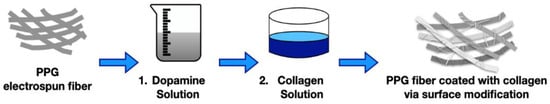
Figure 7.
Schematic of the surface modification process in the coating of PPG with collagen.

Figure 8.
Surface modification of PPG fibers. (A,B) represents SEM images of PDA-coated PPG fibers. (C,D) represents the SEM images of PDA–collagen-coated PPG fibers.
Due to the presence of catechol and amine groups in dopamine, polydopamine (PDA) is known to improve adhesion to a variety of materials and also enable secondary reactions with biomolecules and thiolate compounds [48].
After dopamine coating, the average diameter of the nanofibers did not change significantly since the polydopamine layer was very thin, which is similar to the work done by Ku et al. [49].
3.7. Cytotoxicity Study
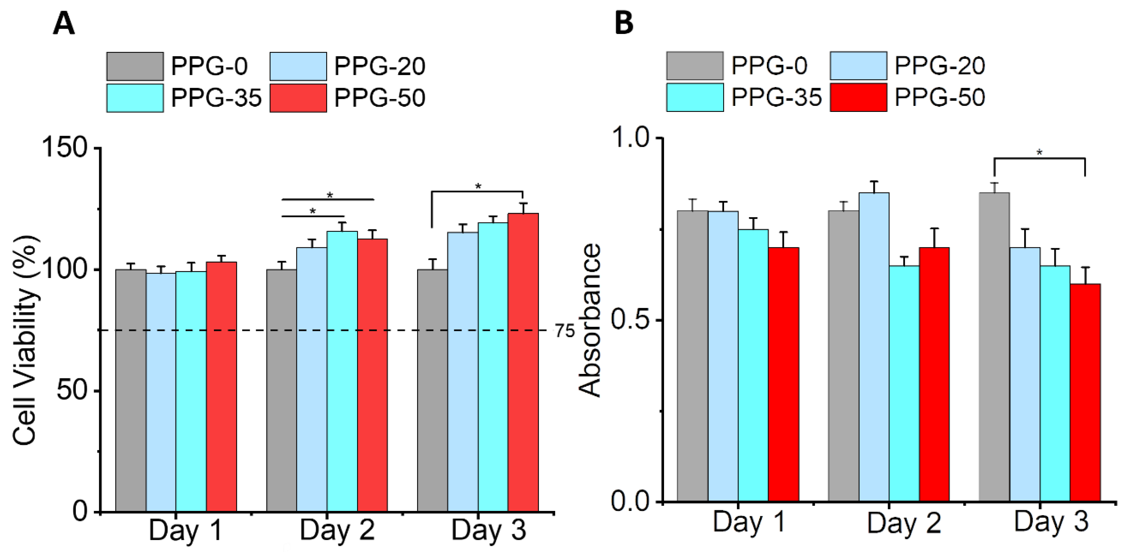
Alamar Blue can be used to access cell proliferation and cellular metabolic activity [50]. Therefore, we used Alamar Blue to compare the effects of different nanofiber membranes on the proliferation of 3T3 fibroblast cells. To assess the cytotoxicity of the fibers, we used an LDH assay which serves as a marker for cell death in vitro. The estimated cell viability and toxicity were graphed as shown in Figure 9A and B, respectively. All samples showed accelerated cell viability, especially the PPG-35 and PPG-50 fibers. PPG-35 and PPG-50 fibers had the lowest release of lactate dehydrogenase and were therefore the least toxic fibers which correspond to their increase in cell viability. These results indicate that the PPG nanofibers have good biocompatibility and low cytotoxicity, and can promote the proliferation of 3T3 fibroblasts.

Figure 9.
Cell viability (A) and LDH cytotoxicity (B) of 3T3 fibroblasts cultured indirectly on PPG fiber mesh for days 1, 2, and 3.
4. Conclusions
This study began the framework for a scaffold that has promising features as a more cost-effective route for tissue regeneration. The SEM images revealed that the morphology and distribution of the fibers support the proliferation of 3T3 fibroblast cells. Also, degradation studies confirm that the addition of PGC to PCL increases the nanofiber degradation rate. Our results suggest that the composite scaffold supports cell proliferation and metabolism as exhibited in the Alamar Blue experiments. The fibers also limit cytotoxicity effects as shown in the lactate dehydrogenase (LDH) assay results. At the endpoint of the study, which was day 3, PPG-50 fibers were superior for cell culture experiments. The mechanical testing outcome also indicates the possibility of increasing loads of fiber while increasing PGC. Considering the overall results of the degradability in vitro, mechanical integrity, biocompatibility, ease of production, and extracellular matrix mimicking properties, PPG-30 and PPG-50 fibrous scaffolds for tissue regeneration seem promising. The PPG scaffold with PDA and collagen coating has great potential in its entirety. These composite scaffolds can be used as an advantageous biomaterial for tissue engineering applications such as for regeneration of human articular cartilage regeneration and soft bones.
Author Contributions
Conceptualization—N.B., F.T., A.M. and J.S.-D.; Methodology—F.T., A.M. and J.S.-D.; Software–F.T. and J.S.-D.; Validation–N.B. and F.T.; Formal Analysis—N.B.; Investigations—N.B., FT., A.M. and J.S.-D.; Resources and Funding Acquisition—N.B.; Data Curation—F.T., A.M. and J.S.-D.; Writing—Original Draft Preparation—F.T., N.B. and A.M.; Writing—Review and Editing—N.B., F.T., A.M. and J.S.-D.; Visualization—F.T.; Supervision and Project Administration—N.B. All authors have read and agreed to the published version of the manuscript.
Funding
This research was funded by the National Science Foundation-Excellence in Research (NSF-EiR, 2100861). Part of this research work was also supported by NSF-Engineering Research Centers, ERC-HAMMER (EEC-2133630) and ERC-RMB (EEC-0812348).
Data Availability Statement
Data are contained within the article.
Acknowledgments
We thank Udhab Adhikari, Shalil Khanal, and Elizabeth Martu for their technical assistance in this research.
Conflicts of Interest
The authors declare no conflict of interest.
References
- Green, J.J.; Elisseeff, J.H. Mimicking biological functionality with polymers for biomedical applications. Nature 2016, 540, 386–394. [Google Scholar] [CrossRef] [PubMed]
- Terzopoulou, Z.; Zamboulis, A.; Koumentakou, I.; Michailidou, G.; Noordam, M.J.; Bikiaris, D.N. Biocompatible synthetic polymers for tissue engineering purposes. Biomacromolecules 2022, 23, 1841–1863. [Google Scholar] [CrossRef] [PubMed]
- Kalirajan, C.; Dukle, A.; Nathanael, A.J.; Oh, T.-H.; Manivasagam, G. A Critical Review on Polymeric Biomaterials for Biomedical Applications. Polymers 2021, 13, 3015. [Google Scholar] [CrossRef]
- Habibzadeh, F.; Sadraei, S.M.; Mansoori, R.; Chauhan, N.P.S.; Sargazi, G. Nanomaterials supported by polymers for tissue engineering applications: A review. Heliyon 2022, 8, e12193. [Google Scholar] [CrossRef]
- Samir, A.; Ashour, F.H.; Hakim, A.A.A.; Bassyouni, M. Recent advances in biodegradable polymers for sustainable applications. npj Mater. Degrad. 2022, 6, 68. [Google Scholar] [CrossRef]
- Socci, M.C.; Rodríguez, G.; Oliva, E.; Fushimi, S.; Takabatake, K.; Nagatsuka, H.; Felice, C.J.; Rodríguez, A.P. Polymeric Materials, Advances and Applications in Tissue Engineering: A Review. Bioengineering 2023, 10, 218. [Google Scholar] [CrossRef] [PubMed]
- Silva, M.; Ferreira, F.N.; Alves, N.M.; Paiva, M.C. Biodegradable polymer nanocomposites for ligament/tendon tissue engineering. J. Nanobiotechnol. 2020, 18, 23. [Google Scholar] [CrossRef]
- Mandal, A.K.; Katuwal, S.; Tettey, F.; Gupta, A.; Bhattarai, S.; Jaisi, S.; Bhandari, D.P.; Shah, A.K.; Bhattarai, N.; Parajuli, N. Current Research on Zinc Oxide Nanoparticles: Synthesis, Characterization, and Biomedical Applications. Nanomaterials 2022, 12, 3066. [Google Scholar] [CrossRef]
- Xu, Q.; Guo, L.; Sigen, A.; Gao, Y.; Zhou, D.; Greiser, U.; Creagh-Flynn, J.; Zhang, H.; Dong, Y.; Cutlar, L. Injectable hyperbranched poly (β-amino ester) hydrogels with on-demand degradation profiles to match wound healing processes. Chem. Sci. 2018, 9, 2179–2187. [Google Scholar] [CrossRef]
- Ulery, B.D.; Nair, L.S.; Laurencin, C.T. Biomedical applications of biodegradable polymers. J. Polym. Sci. Part B Polym. Phys. 2011, 49, 832–864. [Google Scholar] [CrossRef]
- Arrieta, M.P.; Leonés Gil, A.; Yusef, M.; Kenny, J.M.; Peponi, L. Electrospinning of PCL-based blends: Processing optimization for their scalable production. Materials 2020, 13, 3853. [Google Scholar] [CrossRef] [PubMed]
- Mochane, M.J.; Motsoeneng, T.S.; Sadiku, E.R.; Mokhena, T.C.; Sefadi, J.S. Morphology and properties of electrospun PCL and its composites for medical applications: A mini review. Appl. Sci. 2019, 9, 2205. [Google Scholar] [CrossRef]
- Joseph, B.; Augustine, R.; Kalarikkal, N.; Thomas, S.; Seantier, B.; Grohens, Y. Recent advances in electrospun polycaprolactone based scaffolds for wound healing and skin bioengineering applications. Mater. Today Commun. 2019, 19, 319–335. [Google Scholar] [CrossRef]
- Schindler, C.; Williams, B.L.; Patel, H.N.; Thomas, V.; Dean, D.R. Electrospun polycaprolactone/polyglyconate blends: Miscibility, mechanical behavior, and degradation. Polymer 2013, 54, 6824–6833. [Google Scholar] [CrossRef]
- Dhanasekaran, N.P.D.; Muthuvelu, K.S.; Arumugasamy, S.K. Recent Advancement in Biomedical Applications of Polycaprolactone and Polycaprolactone-Based Materials. In Encyclopedia of Materials; Plastics and Polymers; Elsevier: Amsterdam, The Netherlands, 2022; pp. 795–809. [Google Scholar]
- Shahverdi, M.; Seifi, S.; Akbari, A.; Mohammadi, K.; Shamloo, A.; Movahhedy, M.R. Melt Electrowriting of PLA, PCL, and Composite PLA/PCL Scaffolds for Tissue Engineering Application. Sci. Rep. 2022, 12, 19935. [Google Scholar] [CrossRef] [PubMed]
- Sowmya, B.; Hemavathi, A.B.; Panda, P.K. Poly (ε-Caprolactone)-Based Electrospun Nano-Featured Substrate for Tissue Engineering Applications: A Review. Prog. Biomater. 2021, 10, 91–117. [Google Scholar] [CrossRef]
- Patel, H.N.; Garcia, R.; Schindler, C.; Dean, D.; Pogwizd, S.M.; Singh, R.; Vohra, Y.K.; Thomas, V. Fibro-porous poliglecaprone/polycaprolactone conduits: Synergistic effect of composition and in vitro degradation on mechanical properties. Polym. Int. 2015, 64, 547–555. [Google Scholar] [CrossRef]
- Yaseri, R.; Fadaie, M.; Mirzaei, E.; Samadian, H.; Ebrahiminezhad, A. Surface Modification of Polycaprolactone Nanofibers through Hydrolysis and Aminolysis: A Comparative Study on Structural Characteristics, Mechanical Properties, and Cellular Performance. Sci. Rep. 2023, 13, 9434. [Google Scholar] [CrossRef]
- Vilar, G.; Tulla-Puche, J.; Albericio, F. Polymers and Drug Delivery Systems. Curr. Drug Deliv. 2012, 9, 367–394. [Google Scholar] [CrossRef]
- Zhou, Y.; Li, Y.; Li, D.; Yin, Y.; Zhou, F. Electrospun PHB/Chitosan Composite Fibrous Membrane and Its Degradation Behaviours in Different pH Conditions. J. Funct. Biomater. 2022, 13, 58. [Google Scholar] [CrossRef]
- Gautam, S.; Dinda, A.K.; Mishra, N.C. Fabrication and Characterization of PCL/Gelatin Composite Nanofibrous Scaffold for Tissue Engineering Applications by Electrospinning Method. Mater. Sci. Eng. C 2013, 33, 1228–1235. [Google Scholar] [CrossRef] [PubMed]
- Kang, J.; Yun, S. Il Chitosan-reinforced PHB hydrogel and aerogel monoliths fabricated by phase separation with the solvent-exchange method. Carbohydr. Polym. 2022, 284, 119184. [Google Scholar] [CrossRef] [PubMed]
- Molea, G.; Schonauer, F.; Bifulco, G.; D’angelo, D. Comparative Study on Biocompatibility and Absorption Times of Three Absorbable Monofilament Suture Materials (Polydioxanone, Poliglecaprone 25, Glycomer 631). Br. J. Plast. Surg. 2000, 53, 137–141. [Google Scholar] [CrossRef] [PubMed]
- Langley-Hobbs, S.J. Sutures and general surgical implants. In Feline Soft Tissue and General Surgery; Elsevier Ltd.: New York, NY, USA, 2014; pp. 105–116. [Google Scholar]
- Manivasagam, G.; Reddy, A.; Sen, D.; Nayak, S.; Mathew, M.T.; Rajamanikam, A. Dentistry: Restorative and Regenerative Approaches; Narayan, R.B.T.-E., Ed.; Elsevier: Oxford, UK, 2019; pp. 332–347. [Google Scholar]
- Niles, J.; Williams, J. Suture Materials and Patterns. In Pract. 1999, 21, 308–320. [Google Scholar] [CrossRef]
- Trott, A.T. Chapter 8—Instruments, Suture Materials, and Closure Choices. In Wounds Lacerations, 4th ed.; Trott, A.T., Ed.; WB Saunders: Philadelphia, PA, USA, 2012; pp. 82–94. [Google Scholar]
- Khiste, S.V.; Ranganath, V.; Nichani, A.S. Evaluation of Tensile Strength of Surgical Synthetic Absorbable Suture Materials: An in Vitro Study. J. Periodontal Implant. Sci. 2013, 43, 130–135. [Google Scholar] [CrossRef]
- Zhang, X.; Thomas, V.; Xu, Y.; Bellis, S.L.; Vohra, Y.K. An in vitro regenerated functional human endothelium on a nanofibrous electrospun scaffold. Biomaterials 2010, 31, 4376–4381. [Google Scholar] [CrossRef]
- Zhang, X.; Thomas, V.; Vohra, Y.K. Two ply tubular scaffolds comprised of proteins/poliglecaprone/polycaprolactone fibers. J. Mater. Sci. Mater. Med. 2010, 21, 541–549. [Google Scholar] [CrossRef]
- Li, L.; Liu, W.; Zhao, Y.; Ma, P.; Zha, S.; Chen, P.; Lu, H.; Jiang, X.; Wan, S.; Luo, J. Dual-peptide-functionalized nanofibrous scaffolds recruit host endothelial progenitor cells for vasculogenesis to repair calvarial defects. ACS Appl. Mater. Interfaces 2019, 12, 3474–3493. [Google Scholar] [CrossRef]
- Yang, Y.; Zhu, X.; Cui, W.; Li, X.; Jin, Y. Electrospun Composite Mats of Poly [(D, L-lactide)-co-glycolide] and Collagen with High Porosity as Potential Scaffolds for Skin Tissue Engineering. Macromol. Mater. Eng. 2009, 294, 611–619. [Google Scholar] [CrossRef]
- Malakpour-Permlid, A.; Buzzi, I.; Hegardt, C.; Johansson, F.; Oredsson, S. Identification of Extracellular Matrix Proteins Secreted by Human Dermal Fibroblasts Cultured in 3D Electrospun Scaffolds. Sci. Rep. 2021, 11, 6655. [Google Scholar] [CrossRef]
- Nelson, M.T.; Short, A.; Cole, S.L.; Gross, A.C.; Winter, J.; Eubank, T.D.; Lannutti, J.J. Preferential, enhanced breast cancer cell migration on biomimetic electrospun nanofiber ‘cell highways’. BMC Cancer 2014, 14, 1–16. [Google Scholar] [CrossRef] [PubMed]
- Poyraz, Ş.; Altınışık, Z.; Çakmak, A.S.; Şimşek, M.; Gümüşderelioğlu, M. Random/aligned electrospun PCL fibrous matrices with modified surface textures: Characterization and interactions with dermal fibroblasts and keratinocytes. Colloids Surf. B Biointerfaces 2022, 218, 112724. [Google Scholar] [CrossRef] [PubMed]
- Lam, C.X.F.; Hutmacher, D.W.; Schantz, J.; Woodruff, M.A.; Teoh, S.H. Evaluation of polycaprolactone scaffold degradation for 6 months in vitro and in vivo. J. Biomed. Mater. Res. Part A 2009, 90A, 906–919. [Google Scholar] [CrossRef] [PubMed]
- Patel, H.N.; Vohra, Y.K.; Singh, R.K.; Thomas, V. HuBiogel incorporated fibro-porous hybrid nanomatrix graft for vascular tissue interfaces. Mater. Today Chem. 2020, 17, 100323. [Google Scholar] [CrossRef]
- Saudi, S.; Bhattarai, S.R.; Adhikari, U.; Khanal, S.; Sankar, J.; Aravamudhan, S.; Bhattarai, N. Nanonet-nano fiber electrospun mesh of PCL–chitosan for controlled and extended release of diclofenac sodium. Nanoscale 2020, 12, 23556–23569. [Google Scholar] [CrossRef]
- Bastakoti, B.P.; Bhattarai, N.; Ashie, M.D.; Tettey, F.; Yusa, S.; Nakashima, K. Single-Micelle-Templated Synthesis of Hollow Barium Carbonate Nanoparticle for Drug Delivery. Polymers 2023, 15, 1739. [Google Scholar] [CrossRef]
- Tatum, S.D.; Saudi, S.; Tettey, F.; Bhandari, R.K.; Bhattarai, N. A Novel Hydrogel-Bronchial Epithelial Cell Spheroids for Toxicological Evaluation. Biomed. Sci. Instrum. 2021, 57, 4. [Google Scholar] [CrossRef]
- Yin, H.; Gao, M.; Leoni, L.; Han, H.; Zhang, X.; Fu, Z. The therapeutic role of monocyte chemoattractant protein-1 in a renal tissue engineering strategy for diabetic patients. PLoS ONE 2013, 8, e57635. [Google Scholar] [CrossRef]
- Pratten, D.H.; Craig, R.G. Wettability of a Hydrophilic Addition Silicone Impression Material. J. Prosthet. Dent. 1989, 61, 197–202. [Google Scholar] [CrossRef]
- Yang, S.; Leong, K.-F.; Du, Z.; Chua, C.-K. The design of scaffolds for use in tissue engineering. Part I. Traditional factors. Tissue Eng. 2001, 7, 679–689. [Google Scholar] [CrossRef]
- Lacroix, D.; Prendergast, P.J. A mechano-regulation model for tissue differentiation during fracture healing: Analysis of gap size and loading. J. Biomech. 2002, 35, 1163–1171. [Google Scholar] [CrossRef] [PubMed]
- Maher, S.A.; Prendergast, P.J. Discriminating the loosening behaviour of cemented hip prostheses using measurements of migration and inducible displacement. J. Biomech. 2002, 35, 257–265. [Google Scholar] [CrossRef] [PubMed]
- Patel, H.N.; Thai, K.N.; Chowdhury, S.; Singh, R.; Vohra, Y.K.; Thomas, V. In vitro degradation and cell attachment studies of a new electrospun polymeric tubular graft. Prog. Biomater. 2015, 4, 67–76. [Google Scholar] [CrossRef] [PubMed]
- Hetemi, D.; Pinson, J. Surface functionalisation of polymers. Chem. Soc. Rev. 2017, 46, 5701–5713. [Google Scholar] [CrossRef] [PubMed]
- Ku, S.H.; Park, C.B. Human endothelial cell growth on mussel-inspired nanofiber scaffold for vascular tissue engineering. Biomaterials 2010, 31, 9431–9437. [Google Scholar] [CrossRef]
- Bikmulina, P.; Kosheleva, N.; Efremov, Y.; Antoshin, A.; Heydari, Z.; Kapustina, V.; Royuk, V.; Mikhaylov, V.; Fomin, V.; Vosough, M. 3D or not 3D: A guide to assess cell viability in 3D cell systems. Soft Matter 2022, 18, 2222–2233. [Google Scholar] [CrossRef]


Disclaimer/Publisher’s Note: The statements, opinions and data contained in all publications are solely those of the individual author(s) and contributor(s) and not of MDPI and/or the editor(s). MDPI and/or the editor(s) disclaim responsibility for any injury to people or property resulting from any ideas, methods, instructions or products referred to in the content. |
© 2023 by the authors. Licensee MDPI, Basel, Switzerland. This article is an open access article distributed under the terms and conditions of the Creative Commons Attribution (CC BY) license (https://creativecommons.org/licenses/by/4.0/).