
Effects of Incorporating Titanium Dioxide with Titanium Carbide on Hybrid Materials Reinforced with Polyaniline: Synthesis, Characterization, Electrochemical and Supercapacitive Properties


Abstract
:1. Introduction
2. Materials and Methods
2.1. Materials
2.2. Physicochemical Characterization
2.3. Producing TiO2–TiC
2.4. Synthesis of PANI@TiO2–TiC
2.5. Electrochemical Measurements
3. Results
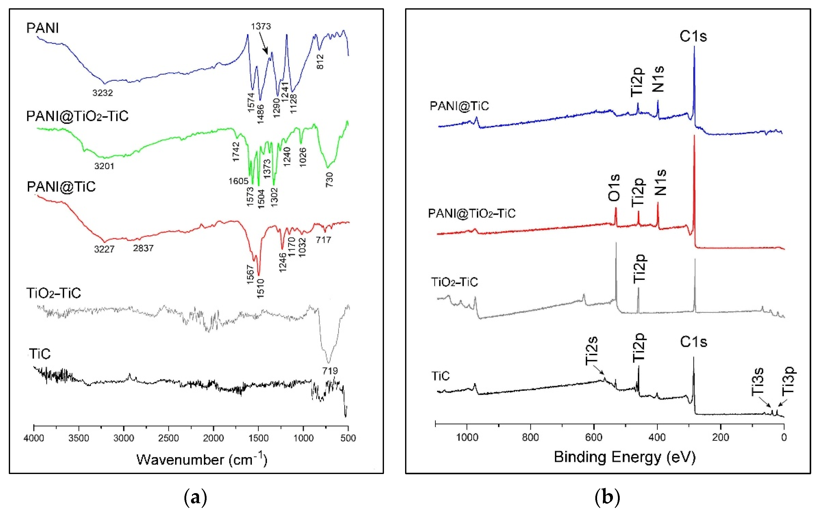
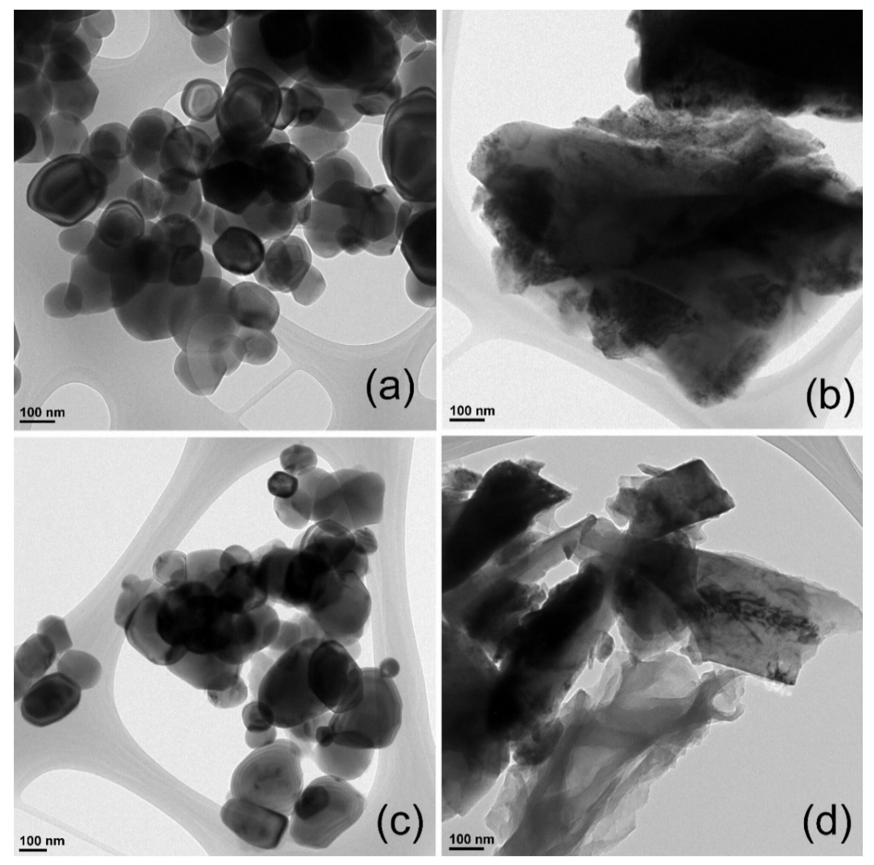
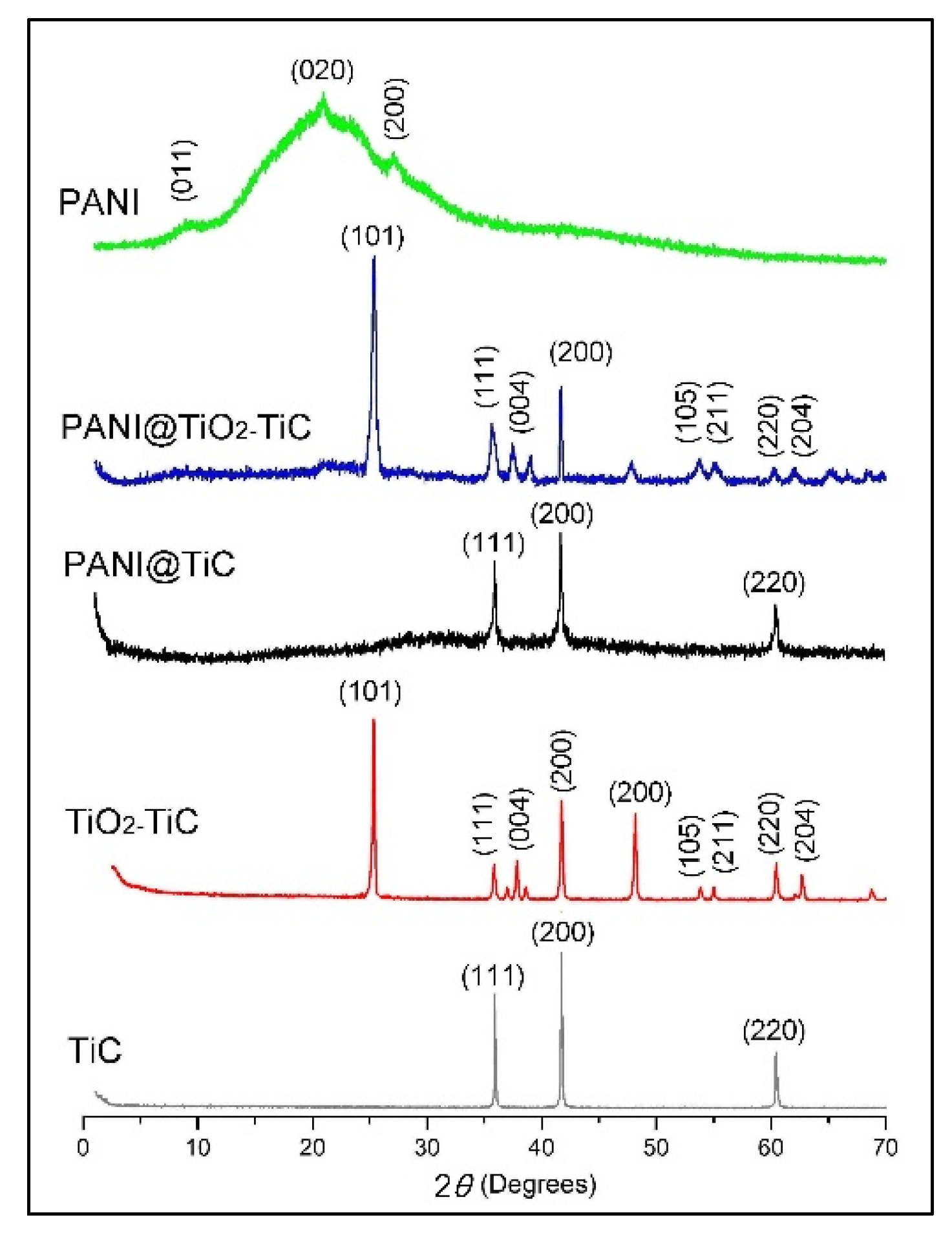
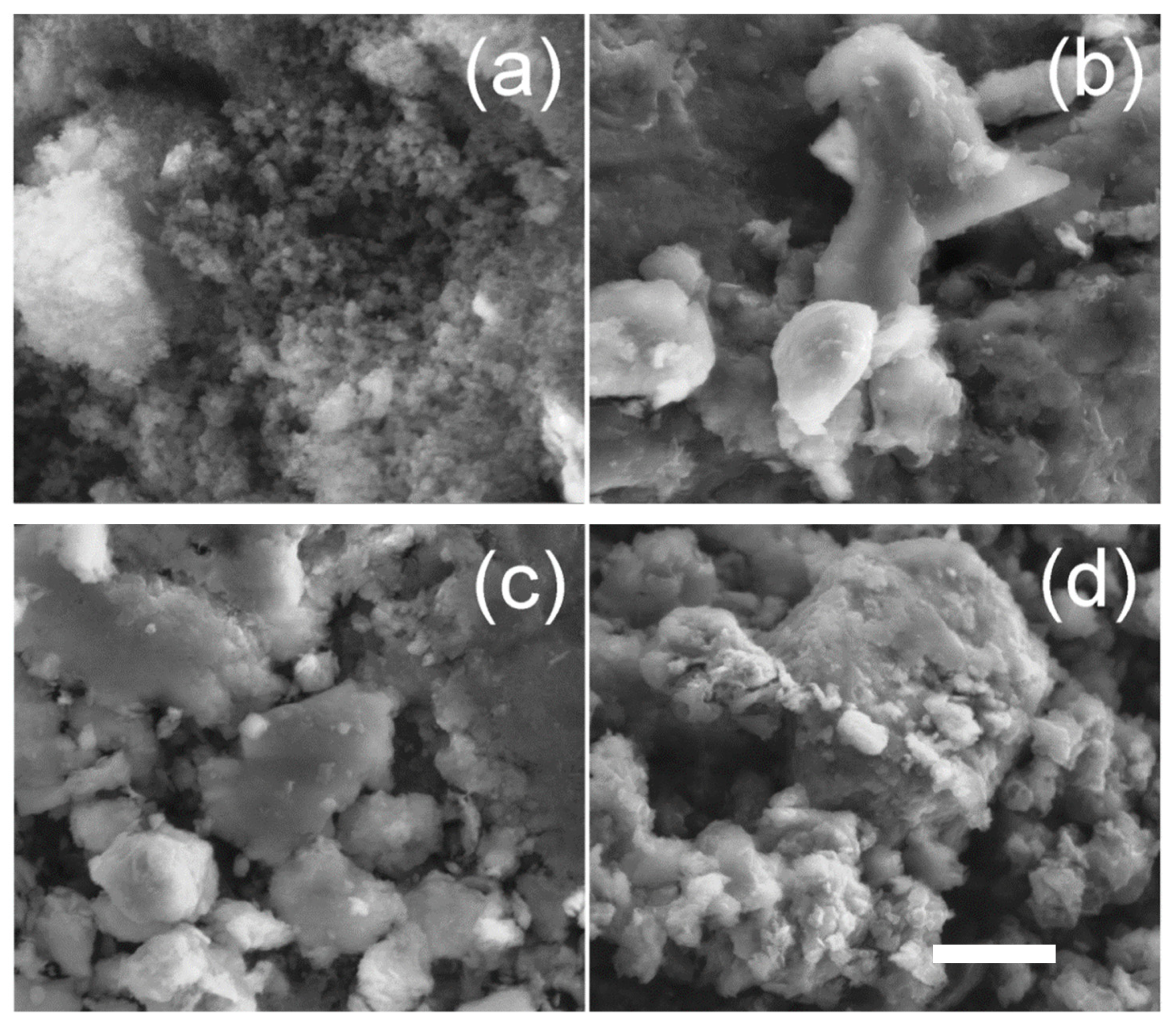
3.1. Structural and Morphological Analysis
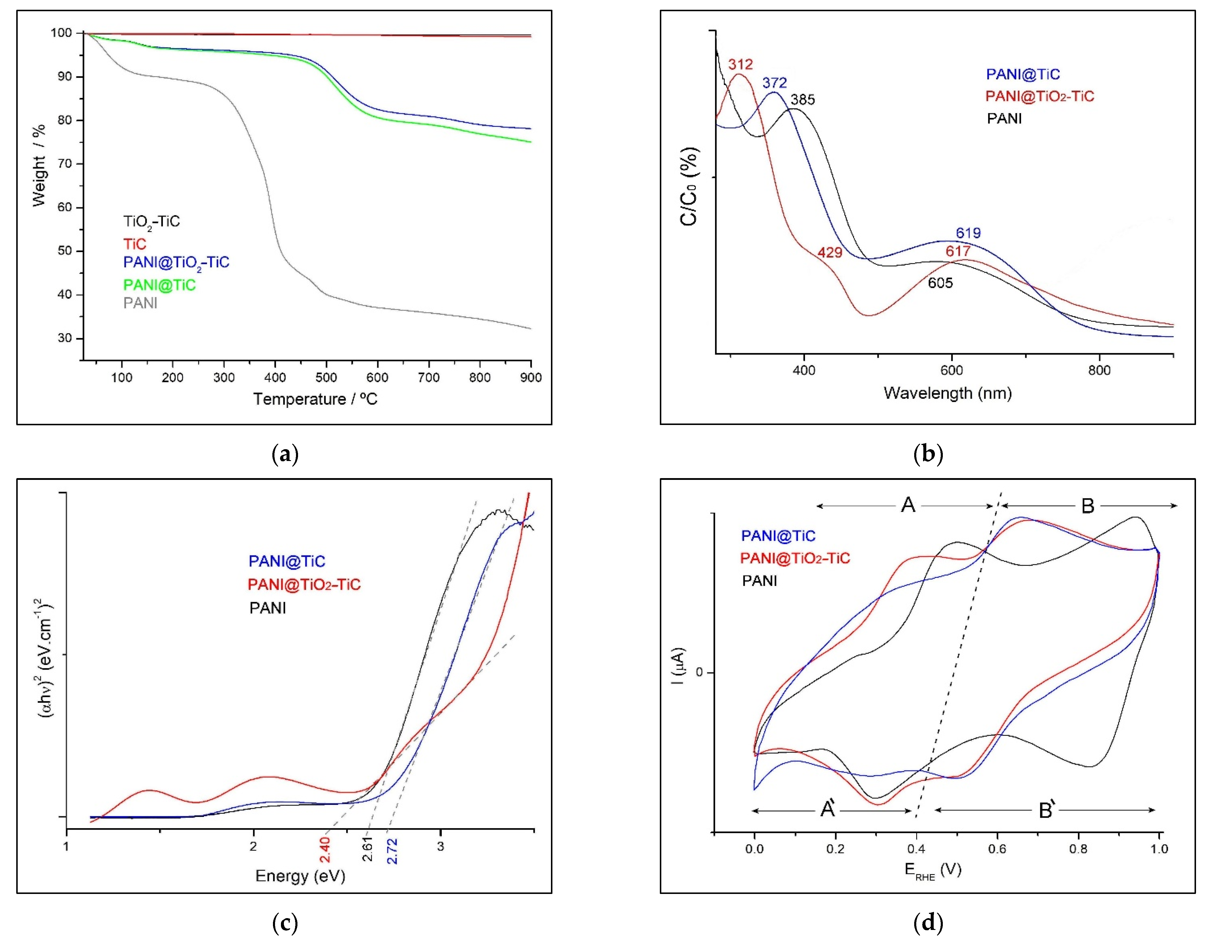
3.2. Electrical Conductivity Measurement
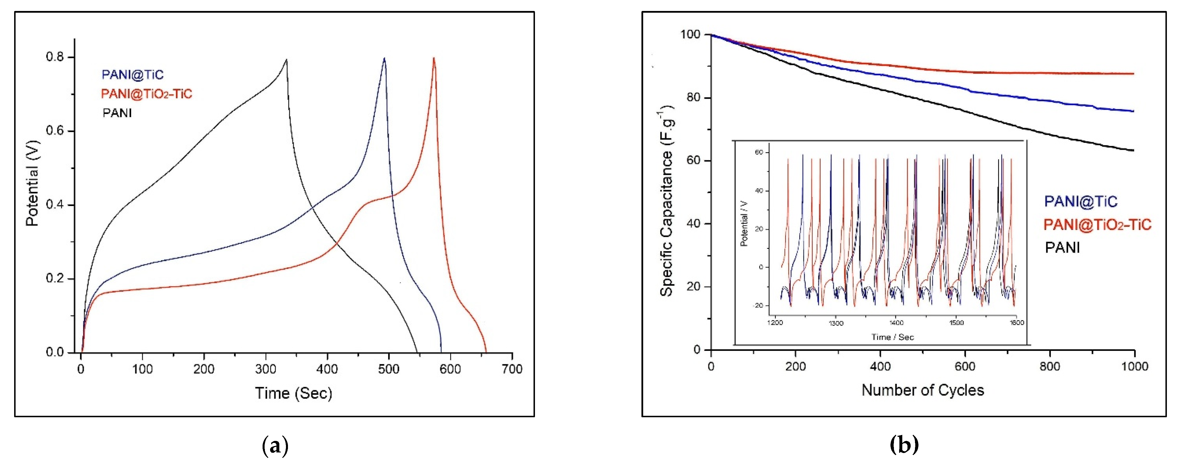
3.3. Electrochemical Performance
4. Conclusions
Author Contributions
Funding
Data Availability Statement
Acknowledgments
Conflicts of Interest
References
- Mahmoud, Z.H.; AL-Bayati, R.A.; Khadom, A.A. Synthesis and supercapacitor performance of polyaniline-titanium dioxide-samarium oxide (PANI/TiO2-Sm2O3) nanocomposite. Chem. Pap. 2022, 76, 1401–1412. [Google Scholar] [CrossRef]
- Abdel Maksoud, M.I.A.; Fahim, R.; Shalan, A. Advanced materials and technologies for supercapacitors used in energy conversion and storage: A review. Environ. Chem. Lett. 2021, 19, 375–439. [Google Scholar] [CrossRef]
- Banitaba, S.N.; Ehrmann, A. Application of Electrospun Nanofibers for Fabrication of Versatile and Highly Efficient Electrochemical Devices: A Review. Polymers 2021, 13, 1741. [Google Scholar] [CrossRef] [PubMed]
- Liang, J.; Zhao, H.; Yue, L.; Fan, G.; Li, T.; Lu, S.; Chen, G.; Gao, S.; Asiri, A.M.; Sun, X. Recent advances in electrospun nanofibers for supercapacitors. J. Mater. Chem. A 2020, 8, 16747–16789. [Google Scholar] [CrossRef]
- Yu, Z.; Tetard, L.; Zhai, L.; Thomas, J. Supercapacitor electrode materials: Nanostructures from 0 to 3 dimensions. Energy Environ. Sci. 2015, 8, 702. [Google Scholar] [CrossRef] [Green Version]
- De, B.; Banerjee, S.; Verma, K.D.; Pal, T.; Manna, P.K.; Kar, K.K. Carbon Nanofiber as Electrode Materials for Supercapacitors. In Handbook of Nanocomposite Supercapacitor Materials II; Kar, K., Ed.; Springer Series in Materials Science; Springer: Cham, Switzerland, 2020; Volume 302. [Google Scholar] [CrossRef]
- Wang, H.; Wang, W.; Wang, H.; Jin, X.; Niu, H.; Wang, H.; Zhou, H.; Lin, T. High Performance Supercapacitor Electrode Materials from Electrospun Carbon Nanofibers in Situ Activated by High Decomposition Temperature Polymer. ACS Appl. Energy Mater. 2018, 1, 431–439. [Google Scholar] [CrossRef]
- Storck, J.L.; Wortmann, M.; Brockhagen, B.; Frese, N.; Diestelhorst, E.; Grothe, T.; Hellert, C.; Ehrmann, A. Comparative Study of Metal Substrates for improved Carbonization of Electrospun PAN Nanofibers. Polymers 2022, 14, 721. [Google Scholar] [CrossRef]
- Storck, J.L.; Hellert, C.; Brockhagen, B.; Wortmann, M.; Diestelhorst, E.; Frese, N.; Grothe, T.; Ehrmann, A. Metallic Supports Accelerate Carbonization and Improve Morphological Stability of Polyacrylonitrile Nanofibers during Heat Treatment. Materials 2021, 14, 4686. [Google Scholar] [CrossRef]
- Storck, J.L.; Brockhagen, B.; Grothe, T.; Sabantina, L.; Kaltschmidt, B.; Tuvshinbayar, K.; Braun, L.; Tanzli, E.; Hütten, A.; Ehrmann, A. Stabilization and Carbonization of PAN Nanofiber Mats Electrospun on Metal Substrates. C 2021, 7, 12. [Google Scholar] [CrossRef]
- Yadav, D.; Amini, F.; Ehrmann, A. Recent advances in carbon nanofibers and their applications—A review. Eur. Polym. J. 2020, 138, 109963. [Google Scholar] [CrossRef]
- Ghebache, Z.; Safidine, Z.; Hamidouche, F. Effect of hematite on the energy storage performance of polyaniline/zeolite HY/α-Fe2O3 nanocomposite supercapacitor electrode. J. Inorg. Organomet. Polym. 2021, 31, 1153–1162. [Google Scholar] [CrossRef]
- Kedir, C.N.; Torres, D.S.; Jaime, A.F.Q.; Benyoucef, A.; Morallon, E. Hydrogels obtained from Aniline and Piperazine: Synthesis, characterization and their application in hybrid supercapacitors. J. Mol. Struct. 2022, 1248, 131445. [Google Scholar] [CrossRef]
- Bekhoukh, A.; Moulefera, I.; Sabantina, L.; Benyoucef, A. Development, Investigation, and Comparative Study of the Effects of Various Metal Oxides on Optical Electrochemical Properties Using a Doped PANI Matrix. Polymers 2021, 13, 3344. [Google Scholar] [CrossRef]
- Shaikh, S.; Lim, J.; Mane, R.; Zate, M.; Han, S.; Joo, O. Template-free electrochemical synthesis and electrochemical supercapacitors application of polyaniline nanobuds. J. Appl. Polym. Sci. 2013, 128, 3660–3664. [Google Scholar] [CrossRef]
- Rahman, S.U.; Röse, P.; Shah, A.U.H.A.; Krewer, U.; Bilal, S.; Farooq, S. Exploring the Functional Properties of Sodium Phytate Doped Polyaniline Nanofibers Modified FTO Electrodes for High-Performance Binder Free Symmetric Supercapacitors. Polymers 2021, 13, 2329. [Google Scholar] [CrossRef]
- Ren, K.; Liu, Z.; Wei, T. Recent developments of transition metal compounds-carbon hybrid electrodes for high energy/power supercapacitors. Nano-Micro Lett. 2021, 13, 129. [Google Scholar] [CrossRef]
- Hassan, A.; Abdulazeez, I.; Salawu, O. Electrochemical deposition and characterization of polyaniline-grafted graphene oxide on a glassy carbon electrode. SN Appl. Sci. 2020, 2, 1257. [Google Scholar] [CrossRef]
- Parveen, N.; Ansari, M.O.; Han, T.H.; Cho, M.H. Simple and rapid synthesis of ternary polyaniline/titanium oxide/graphene by simultaneous TiO2 generation and aniline oxidation as hybrid materials for supercapacitor applications. J. Solid State Electrochem. 2017, 21, 57–68. [Google Scholar] [CrossRef]
- Huv, Z.A.; Xie, Y.L.; Wang, Y.X.; Mo, L.P.; Yang, Y.Y.; Zhang, Z.Y. Polyaniline/SnO2 nanocomposite for supercapacitor applications. Mater. Chem. Phys. 2009, 114, 990–995. [Google Scholar] [CrossRef]
- Larios, L.M.; Mondragón, R.M.; Orozco, R.D.M.; García, U.P.; Alamilla, R.G. Electrochemically-assisted fabrication of titanium-dioxide/polyaniline nanocomposite films for the electroremediation of congo red in aqueous effluents. Synth. Met. 2020, 268, 16464. [Google Scholar] [CrossRef]
- Toumi, I.; Djelad, H.; Chouli, F.; Benyoucef, A. Synthesis of PANI@ZnO Hybrid Material and Evaluations in Adsorption of Congo Red and Methylene Blue Dyes: Structural Characterization and Adsorption Performance. J. Inorg. Organomet. Polym. Mater. 2022, 32, 112–121. [Google Scholar] [CrossRef]
- Zenasni, M.; Jaime, A.Q.; Benyoucef, A.; Benghalem, A. Synthesis and characterization of polymer/V2O5 composites based on poly(2-aminodiphenylamine). Polym. Compos. 2021, 42, 1064–1074. [Google Scholar] [CrossRef]
- Torres, D.S.; Sieben, J.M.; Castelló, D.L.; Amorós, D.C.; Morallón, E. Asymmetric hybrid capacitors based on activated carbon and activated carbon fibre–PANI electrodes. Electrochim. Acta 2013, 89, 326–333. [Google Scholar] [CrossRef] [Green Version]
- Torres, D.S.; Rosas, R.R.; Morallón, E.; Amorós, D.C. Strategies to Enhance the Performance of Electrochemical Capacitors Based on Carbon Materials. Front. Mater. 2019, 6, 115. [Google Scholar] [CrossRef]
- Jasna, M.; Pillai, M.M.; Abhilash, A.; Midhun, P.S.; Jayalekshmi, S.; Jayaraj, M.K. Polyaniline wrapped carbon nanotube/exfoliated MoS2 nanosheet composite as a promising electrode for high power supercapacitors. Carbon Trends 2022, 7, 100154. [Google Scholar] [CrossRef]
- Madhab, B.; Gupta, C.; Maji, P.; Pradip, K. Facile One-Pot Synthesis of Graphene Oxide by Sonication Assisted Mechanochemical Approach and Its Surface Chemistry. J. Nanosci. Nanotechnol. 2018, 18, 902–912. [Google Scholar] [CrossRef]
- Yang, N.; Zhai, J.; Wang, D.; Chen, Y.; Jiang, L. Two-dimensional graphene bridges enhanced photoinduced charge transport in dye-sensitized solar cells. ACS Nano 2010, 4, 887–894. [Google Scholar] [CrossRef]
- Gong, Y.; Tu, R.; Goto, T. High-speed deposition of titanium carbide coatings by laser-assisted metal–organic CVD. Mater. Res. Bull. 2013, 48, 2766–2770. [Google Scholar] [CrossRef]
- El Mel, A.A.; Angleraud, B.; Gautron, E.; Granier, A.; Tessier, P.Y. Microstructure and composition of TiC/a-C:H nanocomposite thin films deposited by a hybrid IPVD/PECVD process. Surf. Coat. Technol. 2010, 204, 1880–1883. [Google Scholar] [CrossRef]
- Natu, V.; Benchakar, M.; Canaff, C.; Habrioux, A.; Célérier, S.; Barsoum, M. A critical analysis of the X-ray photoelectron spectra of Ti3C2Tz MXenes. Matter 2021, 4, 1224–1251. [Google Scholar] [CrossRef]
- Li, Y.; Xia, Z.; Gong, Q.; Liu, X.; Yang, Y.; Chen, C.; Qian, C. Green Synthesis of Free-Standing Cellulose/Graphene Oxide/Polyaniline Aerogel Electrode for High-Performance Flexible All-Solid-State Supercapacitors. Nanomaterials 2020, 10, 1546. [Google Scholar] [CrossRef] [PubMed]
- Lin, T.; Liu, W.; Yan, B.; Li, J.; Lin, Y.; Zhao, Y.; Shi, Z.; Chen, S. Self-Assembled Polyaniline/Ti3C2Tx Nanocomposites for High-Performance Electrochromic Films. Nanomaterials 2021, 11, 2956. [Google Scholar] [CrossRef] [PubMed]
- Guo, Y.; He, D.; Xia, S.; Xie, X.; Gao, X.; Zhang, Q. Preparation of a Novel Nanocomposite of Polyaniline Core Decorated with Anatase-TiO2 Nanoparticles in Ionic Liquid/Water Microemulsion. J. Nanomater. 2012, 2012, 8. [Google Scholar] [CrossRef] [Green Version]
- Lv, P.; Tang, X.; Zheng, R.; Ma, X.; Yu, K.; Wei, W. Graphene/polyaniline aerogel with superelasticity and high capacitance as highly compression-tolerant supercapacitor electrode. Nanoscale Res. Lett. 2017, 12, 630. [Google Scholar] [CrossRef] [Green Version]
- Maaza, L.; Djafri, F.; Belmokhtar, A.; Benyoucef, A. Evaluation of the influence of Al2O3 nanoparticles on the thermal stability and optical and electrochemical properties of PANI-derived matrix reinforced conducting polymer composites. J. Phys. Chem. Solids 2021, 152, 109970. [Google Scholar] [CrossRef]
- You, Y.; Wang, Y.; Tu, L.; Tong, L.; Wei, R.; Liu, X. Interface Modulation of Core-Shell Structured BaTiO3@polyaniline for Novel Dielectric Materials from Its Nanocomposite with Polyarylene Ether Nitrile. Polymers 2018, 10, 1378. [Google Scholar] [CrossRef] [Green Version]
- Ibrahim, K.A. Synthesis and characterization of polyaniline and poly(aniline-co-o-nitroaniline) using vibrational spectroscopy. Arab. J. Chem. 2017, 10, 2668–2674. [Google Scholar] [CrossRef] [Green Version]
- Abutalib, M.M.; Rajeh, A. Preparation and characterization of polyaniline/sodium alginate doped TiO2 nanoparticles with promising mechanical and electrical properties and antimicrobial activity for food packaging applications. J. Mater. Sci. Mater. Electron. 2020, 31, 9430–9442. [Google Scholar] [CrossRef]
- Guan, L.; Yu, L.; Chen, G.Z. Capacitive and non-capacitive faradaic charge storage. Electrochim. Acta 2016, 206, 464–478. [Google Scholar] [CrossRef]
- Saliu, O.D.; Mamo, M.; Ndungu, P.; Ramontja, J. Starch built TiO2 nanoarchitecture with mixed anatase and rutile phase for high energy density supercapacitor electrode. J. Energy Storage 2022, 49, 104155. [Google Scholar] [CrossRef]
- Geng, X.; Yi, R.; Lin, X.; Liu, C.; Sun, Y.; Zhao, Y.; Li, Y.; Mitrovic, I.; Liu, R.; Yang, L.; et al. A high conductive TiC–TiO2/SWCNT/S composite with effective polysulfides adsorption for high performance Li–S batteries. J. Alloys Compd. 2021, 851, 156793. [Google Scholar] [CrossRef]
- Pal, R.; Goyal, S.L.; Rawal, I.; Gupta, A.K.; Ruchi. Efficient energy storage performance of electrochemical supercapacitors based on polyaniline/graphene nanocomposite electrodes. J. Phys. Chem. Solids 2021, 154, 110057. [Google Scholar] [CrossRef]


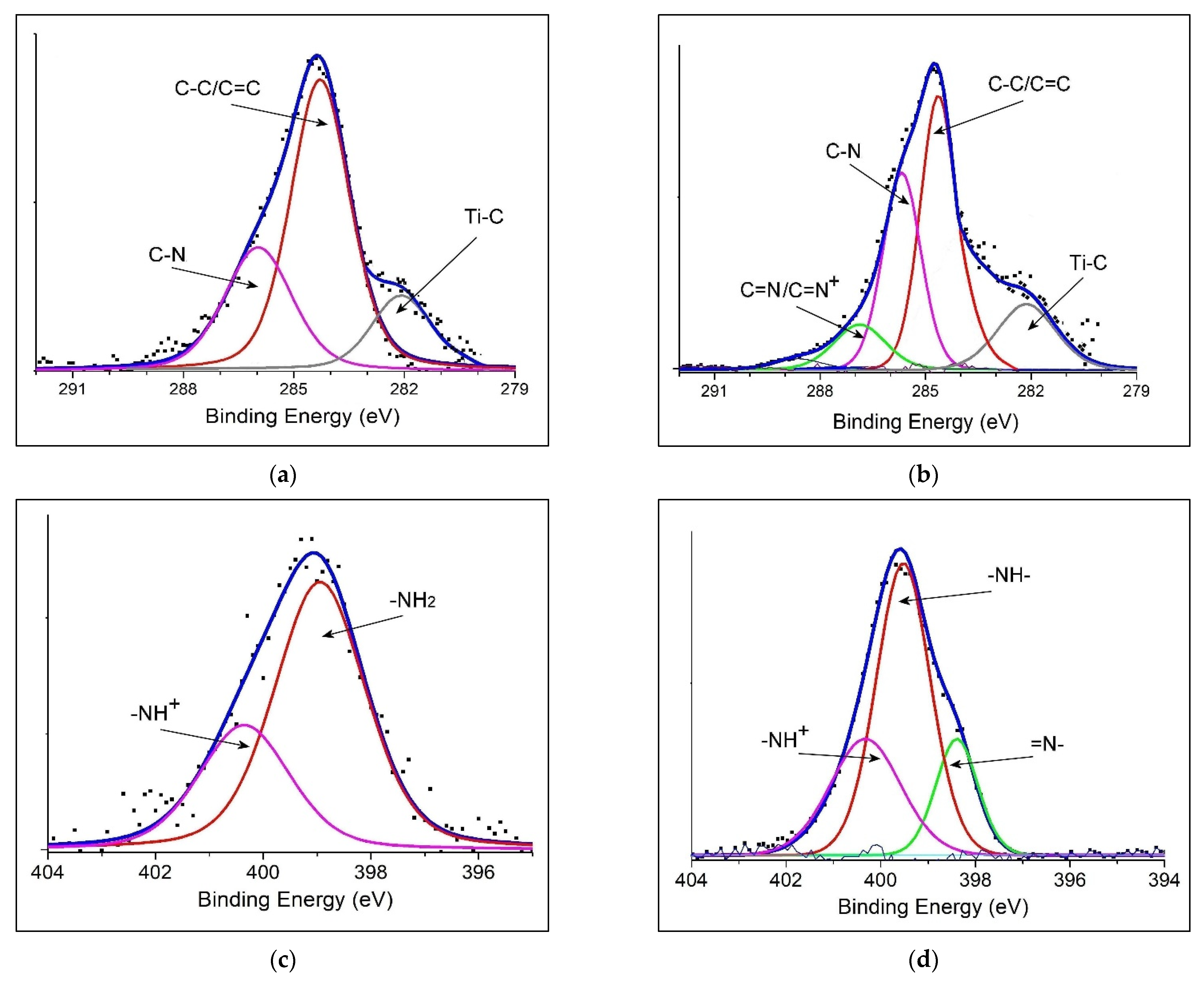
| Binding Energy/eV | PANI@TiC | PANI@TiO2–TiC | Assignments |
|---|---|---|---|
| C1s | 282.14 | 282.17 | Ti–C |
| 284.28 | 284.64 | C=C; C–C | |
| 286.01 | 285.70 | C–N | |
| // | 286.91 | C=N+; C=N | |
| N1s | // | 398.07 | –N= |
| 398.98 | 399.11 | –NH2, –NH– | |
| 400.36 | // | –NH+ | |
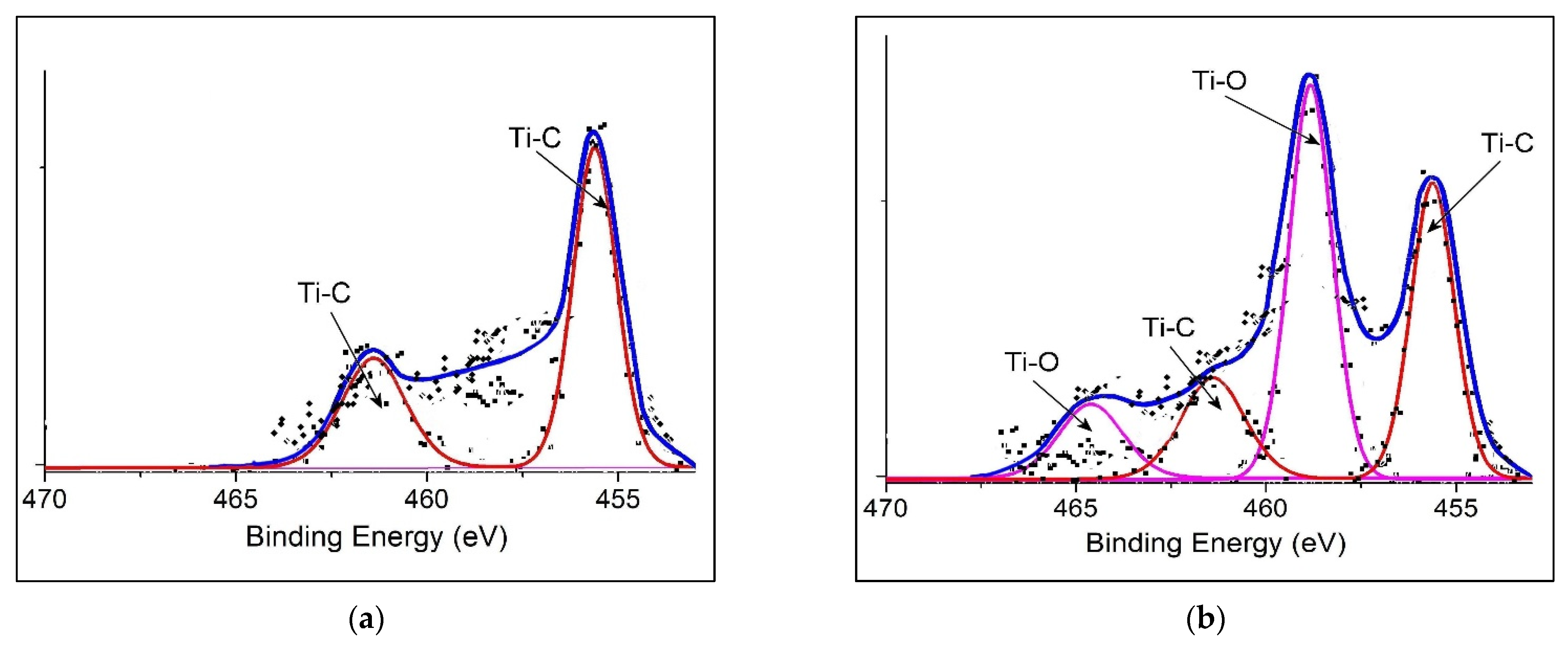
| Ti2p | 455.36 | // | Ti2p3/2 (Ti–C) |
| 467.92 | // | Ti2p1/2 (Ti–C) | |
| // | 458.82 | Ti2p3/2 (Ti–O2) | |
| // | 464.65 | Ti2p1/2 (Ti–O2) |
| Materials | C1s | N1s | O1s | Ti2p | DL* | FD** |
|---|---|---|---|---|---|---|
| PANI@TiC | 80.04 | 10.89 | 2.08 | 6.51 | 0.49 | 0.53 |
| PANI@TiO2–TiC | 69.52 | 11.40 | 10.48 | 8.14 | 0.74 | 0.08 |
| Materials | Redox Peaks/V | Eg/eV | |||
|---|---|---|---|---|---|
| Eox1/red1 | ΔEp1 | Eox2/red2 | ΔEp2 | ||
| PANI | 0.49/0.29 | 0.20 | 0.94/0.82 | 0.12 | 2.64 |
| PANI@TiC | 0.32/0.28 | 0.04 | 0.64/0.54 | 0.10 | 2.72 |
| PANI@TiO2–TiC | 0.38/0.31 | 0.07 | 0.67/0.51 | 0.16 | 2.40 |
Publisher’s Note: MDPI stays neutral with regard to jurisdictional claims in published maps and institutional affiliations. |
© 2022 by the authors. Licensee MDPI, Basel, Switzerland. This article is an open access article distributed under the terms and conditions of the Creative Commons Attribution (CC BY) license (https://creativecommons.org/licenses/by/4.0/).
Share and Cite
Belhadj, H.; Moulefera, I.; Sabantina, L.; Benyoucef, A. Effects of Incorporating Titanium Dioxide with Titanium Carbide on Hybrid Materials Reinforced with Polyaniline: Synthesis, Characterization, Electrochemical and Supercapacitive Properties. Fibers 2022, 10, 46. https://doi.org/10.3390/fib10050046
Belhadj H, Moulefera I, Sabantina L, Benyoucef A. Effects of Incorporating Titanium Dioxide with Titanium Carbide on Hybrid Materials Reinforced with Polyaniline: Synthesis, Characterization, Electrochemical and Supercapacitive Properties. Fibers. 2022; 10(5):46. https://doi.org/10.3390/fib10050046
Chicago/Turabian StyleBelhadj, Hafida, Imane Moulefera, Lilia Sabantina, and Abdelghani Benyoucef. 2022. "Effects of Incorporating Titanium Dioxide with Titanium Carbide on Hybrid Materials Reinforced with Polyaniline: Synthesis, Characterization, Electrochemical and Supercapacitive Properties" Fibers 10, no. 5: 46. https://doi.org/10.3390/fib10050046
APA StyleBelhadj, H., Moulefera, I., Sabantina, L., & Benyoucef, A. (2022). Effects of Incorporating Titanium Dioxide with Titanium Carbide on Hybrid Materials Reinforced with Polyaniline: Synthesis, Characterization, Electrochemical and Supercapacitive Properties. Fibers, 10(5), 46. https://doi.org/10.3390/fib10050046