Article

Effects of Incorporating Titanium Dioxide with Titanium Carbide on Hybrid Materials Reinforced with Polyaniline: Synthesis, Characterization, Electrochemical and Supercapacitive Properties

1
Faculty of Sciences and Technology, University of Mustapha Stambouli, Mascara 29000, Algeria
2
Department of Chemical Engineering, Campus de Espinardo, University of Murcia, 30100 Murcia, Spain
3
Junior Research Group “Nanomaterials”, Faculty of Engineering and Mathematics, Bielefeld University of Applied Sciences, 33619 Bielefeld, Germany
4
L.S.T.E. Laboratory, University of Mustapha Stambouli, Mascara 29000, Algeria
*
Authors to whom correspondence should be addressed.
Fibers 2022, 10(5), 46; https://doi.org/10.3390/fib10050046
Submission received: 14 April 2022 / Revised: 13 May 2022 / Accepted: 19 May 2022 / Published: 23 May 2022
(This article belongs to the Collection Feature Papers in Fibers)

Abstract

:
We report on the synthesis of titanium dioxide by titanium carbide for the preparation of hybrid material reinforced with polyaniline (PANI@TiO2–TiC) using the in situ polymerization technique. The effectiveness of the samples on the thermal, optical and electrochemical properties was investigated. The XRD, XPS, FTIR, SEM and TEM results confirm the successful synthesis of the PANI, PANI@TiC and PANI@TiO2–TiC samples. Through this, a good connection, an excellent relationship between the structures and the properties of the synthesized hybrid materials were obtained. Moreover, the electrical conductivity and optical bandgap were also tested. Remarkably good electrochemical characteristics were identified by cyclic voltammetry. Moreover, the galvanostatic charge–discharge (GCD) of the supercapacitor was remarkably high. Cyclic stability showed good retention after 1500 cycles at 1.5 A·g−1.

1. Introduction

In recent years, supercapacitors have come to be considered potential energy storage devices that facilitate the speedy storage of energy. Supercapacitors (SCs) offer numerous advantages such as excellent efficiency, high power density, good cycling stability and eco-friendliness [1,2,3]. Due to these characteristics, they exhibit practical application qualities in several mobile applications as well as for the storage of energy for photovoltaic cells [4]. However, particular difficulties with regard to the rate of the self-charging and density of energy, cost, etc., limit their actual fields of application to a small number of domains; for these, more investigations will be necessary to overcome these disadvantages. As the efficiency of SCs greatly depends on the electrodes material and electrolytes, conducting polymers (CPs) and nanoparticles that possess pseudocapacitive behavior are considered more favorable or appropriate materials as electrodes. Different nanostructured electrode materials for supercapacitors based on different dimensions ranging from zero to three such as activated carbon, nanorods, nanowires, nanotubes and nanofibers are known [5,6,7]. Recently, electrode materials based on carbon nanofibers, which are prepared by electrospinning technique with subsequent carbonization, are also considered as promising electrode materials for supercapacitors due to their high electrical conductivity and their specific surface area and porosity [8,9,10,11].
Among the several CPs, polyaniline (PANI) is widely utilized because of its excellent energy storage capacity and rapid redox switching, and is thus considered an ideal electrode for SCs [12,13,14]. Consequently, a lot of research on various PANI structures (nanotube, gel, hollow nanofibers, nanobuds, etc.) applied in SCs was published in recent years [15,16]. Although the nanostructure of PANI reveals excellent capacitance, it has been observed that the polymer chain breaks down after charge/discharge cycles. The low solidity and weak durability for the polymer backbone led to reduced cycle stability [17]. This obstacle can be overcome if sufficient stability is supplied to the polymer structure, which can be achieved using nanocomposites [18]. In addition, the PANI-based hybrid material is usually inexpensive, but its main handicap is its weak long-term stability. However, one solution for the above problems appears to be a nanocomposite comprised of inorganic, metal oxides with PANI for excellent capacitance and high stability [19].
In contrast, SCs based on PANI with metal oxides such as SnO2, MnO2, NiO, Al2O3, Co3O4 and TiO2 nanocomposites have been suggested to solve the difficulties in the stability and lofty surface area [14,19,20,21]. The hybrid materials of TiO2–TiC with PANI are expected to have high cycle stability for SC applications owing to the donor and acceptor interactions (p/n junction) between the polymer and inorganic surface, as TiO2 is a perfect n-type composite whereas PANI is a p-type polymer [21]. Moreover, there has been little research on the supercapacitive properties of the PANI@TiO2′s hybrid structure. Among the various nanocomposites based on PANI, PANI@TiO2–Sm2O3 exhibits an interesting structure with a set of properties that are unrivaled by those of other metal oxides [1]. Herein, we demonstrate a simple process to produce PANI@TiO2–TiC to address this challenge. In order to confirm the structure as well as the optical properties and thermal stability of these samples, XPS, XRD, FTIR, TGA, TEM and UV–vis were used. Finally, the electrochemical behavior and cycle stability tests by CV were used to investigate the application of these hybrid materials in the field of SCs.

2. Materials and Methods

2.1. Materials

The solutions were prepared using deionized H2O (18.2 MΩcm, ELGA LabWater, Lane End, UK) obtained with the “Elga Labwater Purelab” system, titanium carbide (TiC) (Aldrich, ≥99.8%, 50 nm, St. Louis, MI, USA), ammonium persulfate (APS) (Aldrich, ≥98%, St. Louis, MI, USA), aniline (ANI) (Aldrich, ≥99.5%, St. Louis, MI, USA), ammonia solution (NH4OH) (Aldrich, 25%, St. Louis, MI, USA), acetylene carbon black (ACB), polyvinylidene difluoride (PVDF) (CH2CF2)n, N-methyl-2-pyrrolidone (NMP) (Aldrich, ≥99.9%, St. Louis, MI, USA), hydrochloric acid (HCl) (Aldrich, 70%, St. Louis, MI, USA), nitric acid (HNO3) (Aldrich, 70%, St. Louis, MI, USA), potassium hydroxide (KOH) (Merck KGaA, 37%, Darmstadt, Germany) and ethanol (C2H5OH) (Merck KGaA, 96%, Darmstadt, Germany).

2.2. Physicochemical Characterization

A H7500-Hitachi (Tokyo, Japan) transmission electron microscope (TEM) was used to examine the microstructure. The surface and morphological characterization of the samples was performed with a scanning electron microscope (SEM; Hitachi S-4700). Bruker CCD-Apex (Madison, WI, USA) X-ray powder diffraction (XRD) with a CuKα target was used to determine the main crystallinity parameters. The thermal stabilization of the samples’ structure was examined using a thermogravimetric analysis (TGA) apparatus, the Hitachi STA7200 (Tokyo, Japan). The optical characteristics were determined using a Hitachi-U3000 spectrophotometer (Tokyo, Japan). Fourier transform infrared (FT-IR) spectra were registered between 500 and 4000 cm−1 (Bruker Instruments, Karlsruhe, Germany). The elemental composition and phase structures were determined by X-ray photoelectron spectroscopy (XPS) (3000 electron, AVG-Microtech-Multilab, London, UK). Electrical conductivity measurement was carried out using the 4-point probes method with a Lucas Lab probe. The samples were dried at 70 °C for 24 h, and then disks were prepared with an FTIR mold [14,22].

2.3. Producing TiO2–TiC

TiO2–TiC was produced in a 1-step H2O bath reaction. First, 1.5 g TiC was weighed as the raw product for TiO2 preparation. Second, as the solvent, 50 mL of HNO3 (7 M) was mixed with 100 mL of C2HOH. Subsequently, the TiC powder was added to the mixed solution and stirred for 15 min. The suspension was then stirred at 70 °C for 12 h by a magnetic stirrer. Finally, the obtained material (marked as TiO2–TiC) was filtered through filter paper and then washed several times with H2O and C2H5OH. The filtered TiO2–TiC was placed in a dryer at 60 °C for 24 h [22].

2.4. Synthesis of PANI@TiO2–TiC

We dispersed 1.20 g TiO2–TiC and 0.56 g of ANI in an ultrasonic bath for 15 min and then dissolved 0.265 mL of HCl in 160 mL of H2O which was then added to the mixture. This solution was stirred at room temperature for 30 min. Then, 0.56 g of APS, which had been stirred with 30 mL of H2O, was added to it. The mixture was then stirred with a magnetic stirrer for another 24 h. Finally, the PANI@TiO2–TiC obtained during the centrifugation process was washed several times with H2O and C2H5OH and placed in a dryer at 70 °C overnight [23]. The PANI@TiC was prepared following the same routine for comparison.

2.5. Electrochemical Measurements

The electrochemical properties of the prepared samples were examined using cyclic voltammetry (CV) and galvanostatic charge–discharge testing (GCD) techniques. Electrodes were prepared by mixing electroactive materials, ACB and PVDF at a mass ratio of 80/10/10 in NMP to form homogeneous slurry [24,25,26]. The slurry was then coated on a carbon cloth current collector. Finally, the coated carbon fabrics were dried in a 75 °C oven for 24 h. After drying, it was cut into discs to form working electrodes. The mass loading of active material was approximately 1.5 mg. The Swagelok 2-electrode supercapacitor test cell was assembled using hybrid materials as the working electrode and 1M HCl aqueous solution as the electrolyte. Electrochemical tests were performed in the potential range from 0 to 1.0 V, and EIS measurements were performed in the frequency range of 200 kHz-10 mHz at open circuit potential with an amplitude of 50 mV [26].

3. Results

3.1. Structural and Morphological Analysis

Figure 1a shows the FTIR analysis of the TiC, TiO2–TiC, PANI, PANI@TiC and PANI@TiO2–TiC samples. The absence of any significant bands in the TiC spectra suggests the chemical inertness of this material [27]. Meanwhile, the TiO2–TiC composite spectrum showed a strong absorption band at 719 cm−1, demonstrating a Ti–O–Ti bond in this new composite [28]. Moreover, the IR spectra of PANI show the principal characteristic peaks of the samples at 1574 cm−1, 1486 cm−1, 1373 cm−1, 1290 cm−1 and 812 cm−1, in line with the findings from literature [14]. The spectrum shows two bands in the region of 1574 cm−1 and 1486 cm−1 belonging to the stretching vibrations of the quinoid (Q) and benzenoid (B) units of polyaniline [14,23]. The band at 1373 cm−1 is due to the C‚ N+ stretching adjacent to the Q structure while a band near 1290 cm−1 can be attributed to C–N stretching vibration in the alternate rings of Q–B–Q units. The two bands at 1373 cm−1 and 1290 cm−1 can be attributed to N–H bending and the symmetric component of the C–C (or C–N) stretching modes. The band at 1241 cm−1 corresponds with the B–(NH+) and Q structure, created during the protonation process. The peak at approximately 1574 cm−1 proves the existence of a protonated imine, and the band at 1290 cm−1 is characteristic of conducting a protonated form of PANI. Finally, the band at 3232 cm−1 corresponds with the N–H stretching frequency. Additionally, all absorption peaks appearing in pure PANI are in the proper position for PANI@TiO2–TiC, but these peaks are slightly shifted toward a higher wavenumber value. Moreover, a new band clearly appeared at 730 cm−1 linked to Ti–O–Ti, suggesting the formation of TiO2 molecules in the studied TiC. In contrast, the FTIR spectra of PANI@TiC display a decrease in the intensity of most bands compared with pure PANI spectra. Additionally, the band at 1373 cm−1 was observed to disappear. Furthermore, the band relating to Q moved to 1567 cm−1, decreasing and becoming broader at the same time.
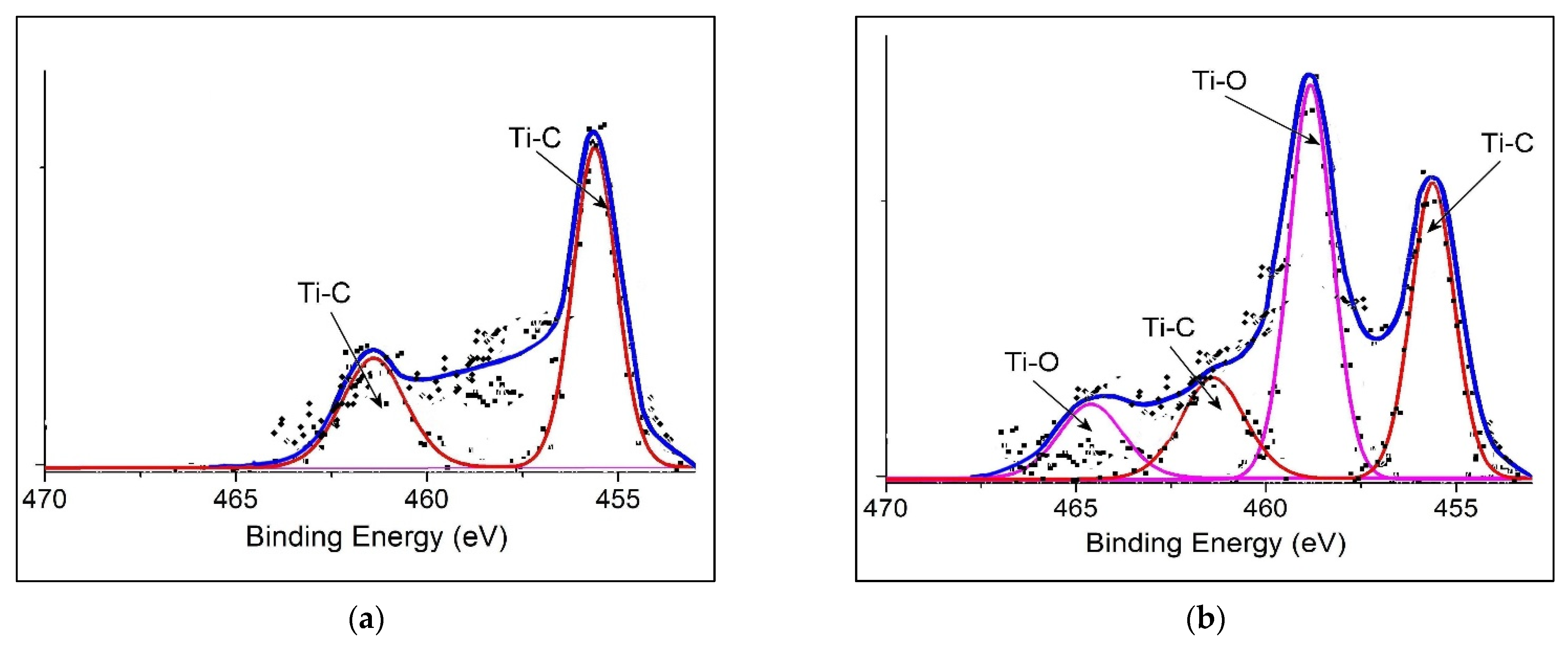
Figure 1b depicts the XPS scan spectra of the bonding states and chemical structure of the synthesized materials, as summarized in Table 1. Prevailing signals of Ti and C were discovered in the TiC material. Aside from the predominant signals, a low signal intensity of oxygen also appeared. The apparition of O can also be understood as the consequence of surface adsorption [29]. Likewise, for the TiO2–TiC composite, an increase in the signal intensity of oxygen was detected by XPS, indicating that important quantities of TiO2 were formed and incorporated into the composite. Furthermore, the C, O, N, and Ti elements were present in the PANI@TiO2–TiC sample. Therefore, it can be concluded that matrix PANI were successfully synthesized in the TiO2–TiC composite. In addition, the XPS spectrum for the Ti2p region from TiC and TiO2–TiC is shown in Figure 2, presenting the familiar Ti2p3/2 and Ti2p1/2 binding energies [30], again proving the existence of Ti–C bonding in both samples. As expected, the Ti2p zone has peaks at the Ti–C binding energy of 455.36 eV and 461.42 eV, suggesting the presence of TiC material in the formed TiO2–TiC composite [31]. Moreover, the XPS spectrum of Ti2p core levels was acquired from the surface of TiO2–TiC composite. The strong TiO2 peaks suggest that a major proportion of the composite’s surface mainly consisted of this oxide type; the two new components associated with Ti2p3/2 and Ti2p1/2 were set at 458.82 eV and 464.65 eV, respectively.
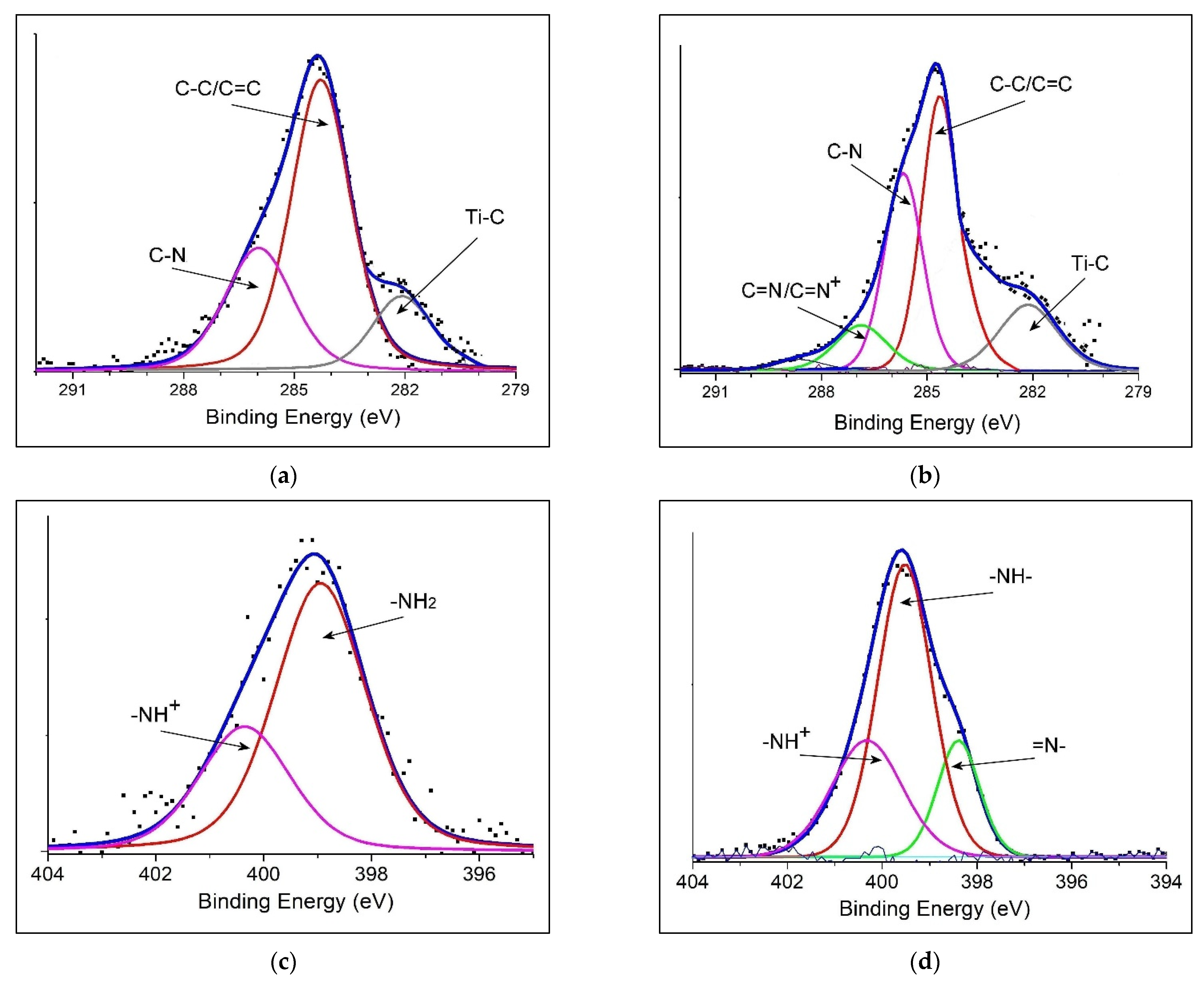
For the typical signals of the C1s spectrum of hybrid materials (Figure 3a,b), for PANI@TiC, the three main characteristic peaks were located at approximately 282.14 eV, 284.28 eV and 286.01 eV, which corresponded to the Ti–C (11.21%), (C–C/C=C, 41.54%) and (C–N, 28.92%) components, respectively. Furthermore, the main peak line of PANI@TiO2–TiC can be decomposed into four constituent peaks: 282.17 eV (Ti–C, 9.84%), 284.64 eV (C–C/C=C, 34.43%), 285.70 eV (C–N, 31.72%) and 286.91 eV (C=N/C=N+, 16.55%) [32]. A comparatively higher ratio of C=N/C=N+ to C–N bonds in the PANI@TiO2–TiC material (41.82%) was found, which could be linked to the interactions of the amine functional group of the polymer matrix with the TiO2–TiC composite.
Additionally, as can be been seen in Figure 3c, the N1s of PANI@TiC contains two kinds of electronic states of the benzenoid amine (–NH2) at 398.98 eV and the cationic radical (–NH+) at 400.36 eV, respectively [32,33]. Moreover, the N1s core-level spectrum of PANI@TiO2–TiC (Figure 3d) demonstrated three main peaks at 398.07 eV, 399.11 eV and 400.36 eV, which can be attributed to quinoid imine (=N–), benzene amine (–NH–) and (–NH+), respectively. Furthermore, the oxidation degree and protonation of the PANI chain can be measured by analyzing the ratios of (–N=), (–NH–) and (–NH+) [33]. The PANI contained in the hybrid materials amounted to 26.57% (=N–) and 65.84% (–NH–). The ratio of (–N=) to (–NH–) was approximately 0.11 for the PANI@TiC sample, whereas the PANI@TiO2–TiC material contained 18.91% (=N–) and 46.23% (–NH–), with the ratio of (=N–/–NH–) higher at 0.41. In particular, the total of (–NH+) in the PANI@TiO2–TiC is higher than in the PANI@TiC nanocomposite, resulting in a comparatively higher doping level (DL) of PANI into PANI@TiO2–TiC. The increased ratio of –NH+ could be due to the interactions between the PANI matrix and the TiO2–TiC composite that links to the restructuring of the (–NH2) group in the PANI backbone [34], which also corresponds to the analysis results of the C1s spectra. Additionally, the high (DL) of the polymer in PANI@TiO2–TiC is expected to improve its pseudocapacitive performance as electrodes [34,35]. Additionally, the (DL) was specified from the area proportion of major binding energy bands to the total band area (TBA), and the defect density (DD) from the area proportion of the lowest binding energy band to the TBA (Table 2). The (DL) of PANI@TiC is only 0.49 and the flaws density (FD) is ~0.53, while the PANI@TiO2–TiC has an acceptable DL (0.74) and weak FD (0.08) which probably results in its more rapid charge–discharge rate and considerable capacitance [13].
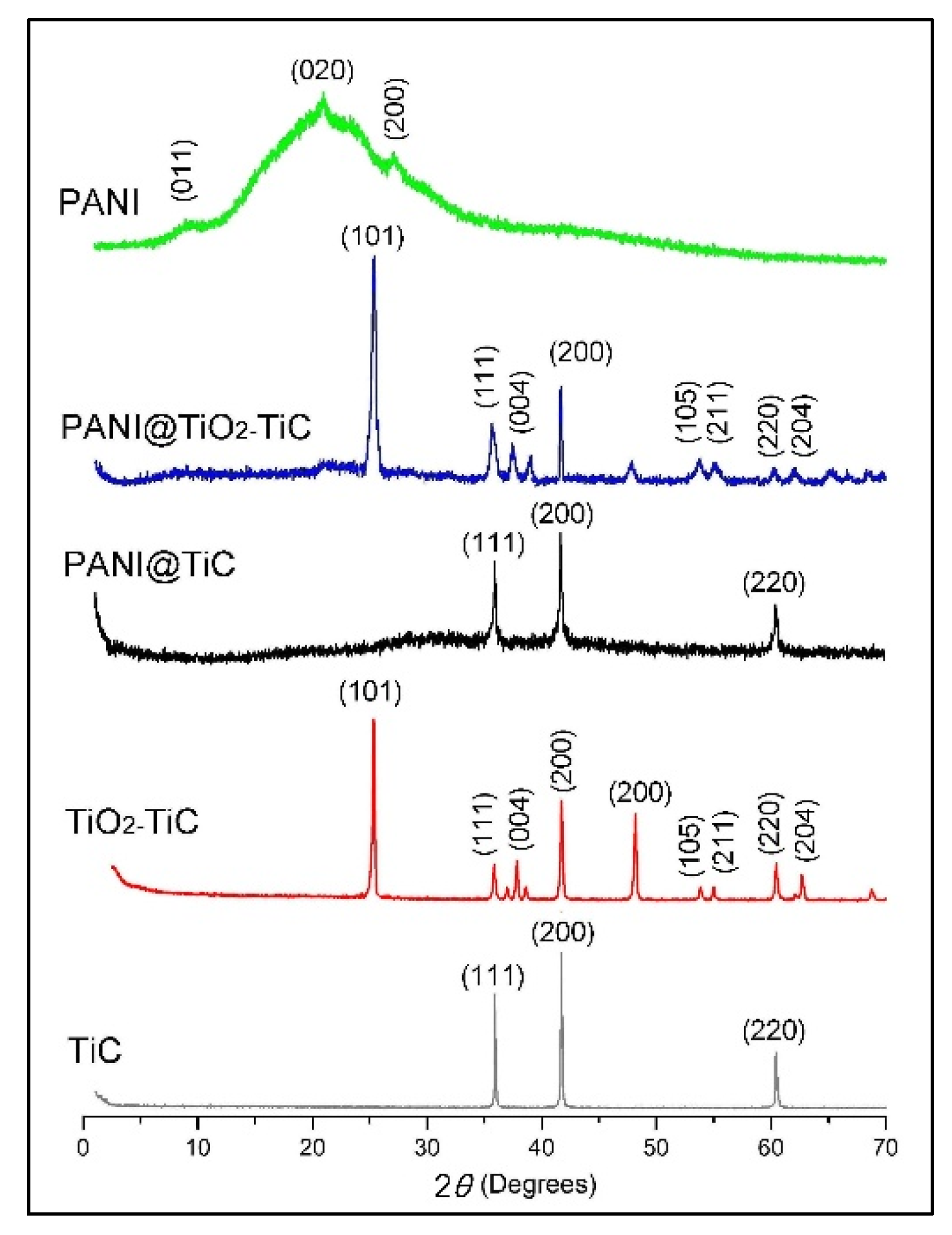
Figure 4 shows the XRD patterns of all samples. The characteristic peaks of TiC appear at 35.88°, 41.67° and 60.42°, which can be attributed to the (111), (200) and (220) crystal plane of TiC, respectively. For the TiO2–TiC composite along with all three intense peaks of TiC, seven other peaks of TiO2 were observed at 25.35° (101), 37.48° (004), 48.10° (200), 53.90° (105), 55.13° (211), 62.75° (204) and 68.80° (116). Finally, the diffraction pattern of the as-prepared materials displays the combinational peak signals of both TiC (JCPDs 65-7994) and TiO2 (JCPDs 89–4921), showing the crystal morphology and successful formation of the nanocomposite structure. Furthermore, PANI is semi-crystalline in character, as the patterns illustrate three clear peaks at 2θ = 9.16° (011), 20.98° (020) and 26.24° (200) due to the existence of Q with B rings in the PANI backbone [36]. Additionally, it is evident that the characteristic absorption peaks of TiC and TiO2–TiC are reserved in PANI@TiC and PANI@TiO2–TiC, respectively. Moreover, a further weak peak between 20° and 30° appertaining to the characteristic absorption peak of the polymer chain [37] shows the formation of the core–shell structure hybrid materials when comparing them with the graphs of neat TiC and TiO2–TiC. These results confirm that the hybrid materials were successfully prepared by in situ polymerization technology.
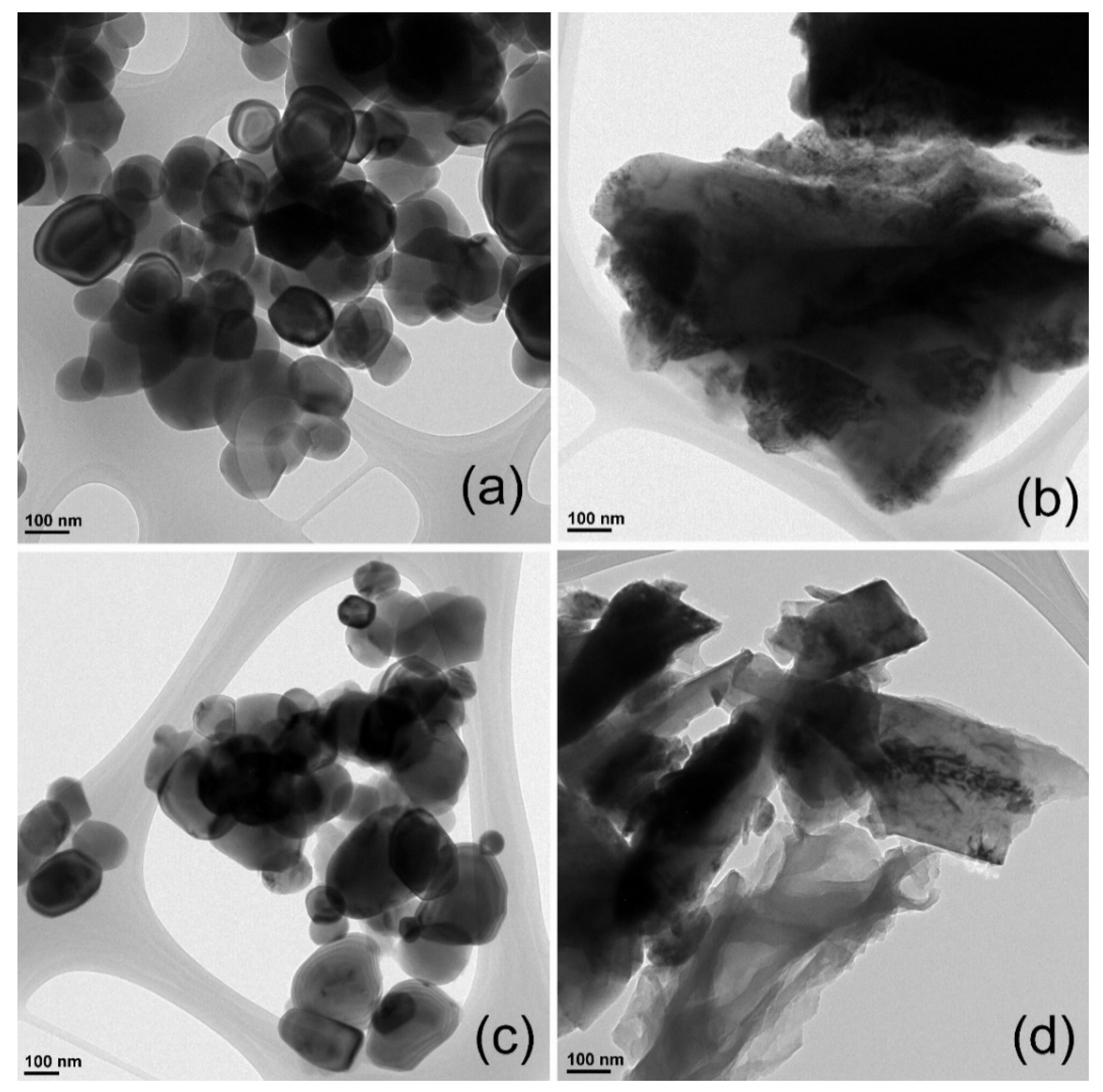
The studied materials are clearly displayed on their transmission electron microscopy (TEM) images in Figure 5. The TiC in Figure 5a appears almost spherical and distributed on the supports. Moreover, we found that the TiO2–TiC composite does not significantly change the size of neat TiC, as shown in Figure 5c. This TEM analysis confirmed that the TiO2–TiC composite was synthesized and successfully prepared from TiC. Furthermore, TEM (Figure 5b,d) revealed the relatively small-sized TiC and TiO2–TiC dispersed and anchored on the PANI backbone in the PANI@TiC and PANI@TiO2–TiC composites, respectively. The result of the TEM analysis suggests that hybrid materials were completely produced.
SEM images of TiC, PANI@TiC, TiO2–TiC and PANI@TiO2–TiC are given in Figure 6. It is observed that the morphological structure of PANI synthesized on the TiC surface (Figure 6b) is different from the structure of pure TiC (Figure 6a). However, PANI consists of interconnected forms in the presence of TiO2–TiC composite (Figure 6c). Additionally, the images in Figure 6d proved not only the full coverage of the TiO2–TiC but also the massive accumulation of PANI on the TiO2–TiC surface compared to the PANI@TiC image. The adjustable morphological structure is very advantageous for supercapacitor applications, as the electrolyte diffusion distance can be lowered by adjusting the thickness controlled by the TiO2–TiC. Moreover, the strong interactions between TiO2–TiC and PANI components were determined by the FTIR spectrum, XRD analysis and XPS analysis, which was also confirmed by SEM images.
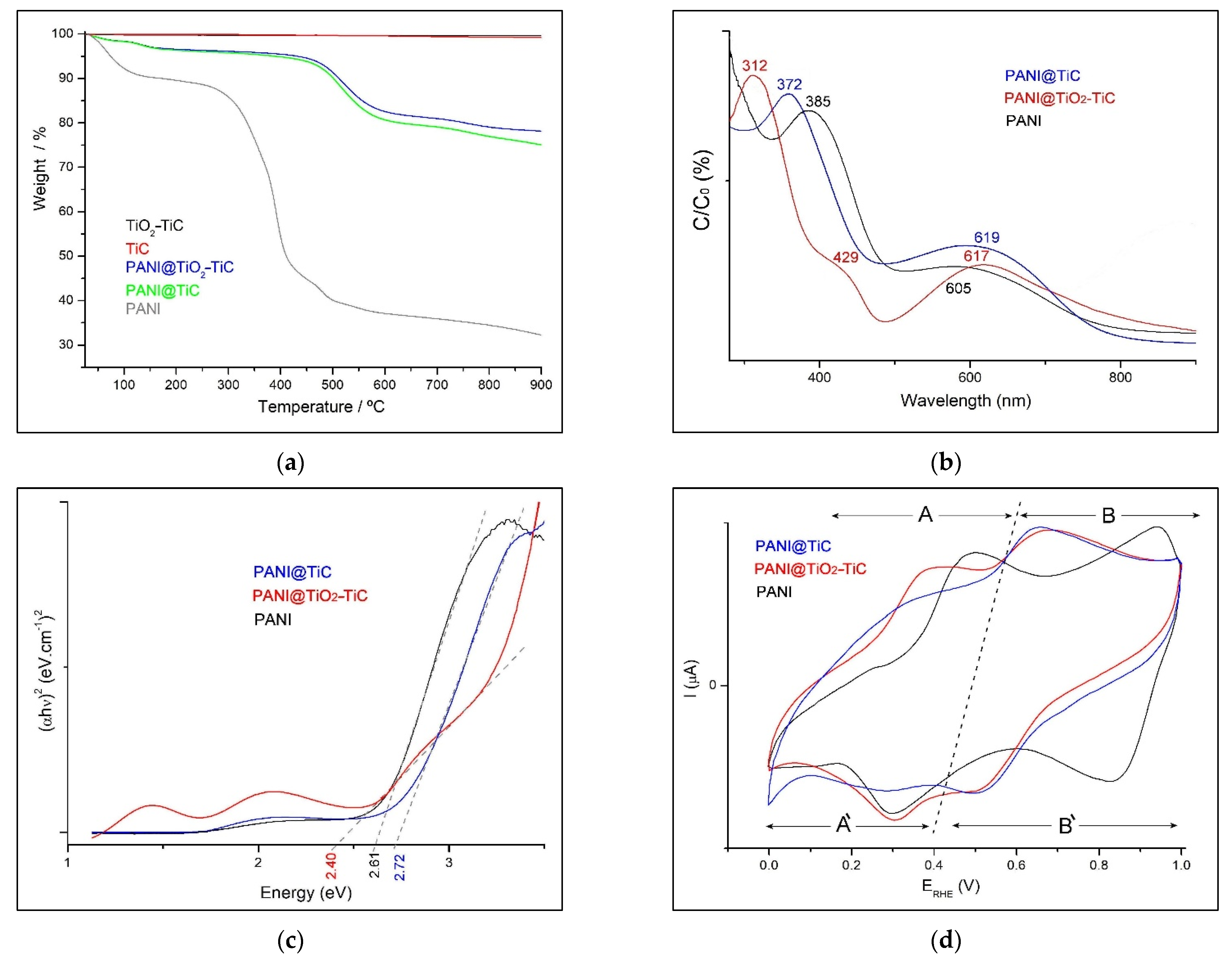
To explore the thermal stability of materials, thermal studies were conducted by utilizing TGA analyses in the temperature range of 25–900 °C as in Figure 7a. The prepared TiC presents thermal stability up to 900 °C where the loss of mass due to the degree of humidity is negligible (0.7%). Meanwhile, the thermal degradations of the TiO2–TiC composite are more stable than those of TiC. In contrast, hybrid materials exhibited weight loss in four major instances. Weight loss occurring at approximately 105 °C may be assigned to the expulsion of H2O molecules or the content of humidity present in the polymer. A weight loss between 105 °C and 190 °C was attributed to the loss of H2O in crystallization. The weight loss that occurred at 440 °C was assigned to the breaking of bonds forming the PANI chain. The final weight loss at 900 °C was associated with the thermal degradation of the materials. Overall, the weight loss of PANI@TiC is 24.88% and that of PANI@TiO2–TiC is 21.84% in the temperature range from 25 °C to 900 °C, while PANI exhibited an important weight loss of more than 67.68% up until 900 °C. Even though temperature changes affect the products’ properties, the synthesis of hybrid materials-based TiC or TiO2–TiC improves the efficiency of these nanocomposites compared to pure PANI, and this performance is related to the strength and durability of the bond between the inorganic composites and the PANI matrix.
The UV–visible absorption spectra of the prepared materials are compared in Figure 7b where these materials were dissolved in THF. Both the graph of pure PANI and that of PANI@TiC show two bands at 372–385 nm and 605–619 nm assigned to transition B and Q, respectively, which is consistent with the molecular structure of the emeraldine base form. The first identified absorption band can be attributed to the π–π* transition in the B unit. The second absorption band is assigned to the transition Q unit (charge transfer from HOMO of the B unit to LUMO of the Q unit) [38]. These bands provide information on the general oxidation state of PANI. Conversely, we can clearly observe the characteristic bands of the PANI@TiO2–TiC sample at approximately 312 nm and a broad band with a maximum at approximately 617 nm, which relates to the electronic transition of polaronic species and emeraldine salt, respectively. In addition, this spectrum showed a new absorption band at approximately 429 nm, probably due to the presence of TiO2 in PANI@TiO2–TiC.
The optical bandgap (Eg) of hybrid materials was measured by Tauc’s relation [14,39]:
( a h ν ) n = B ( h ν E g )
where h ν is the incident photon energy and n = 2 allowed for direct transition. Where the linear dependence of the ( a h ν ) 2 versus h ν occurs at higher photon energy, Figure 7c displays that the Eg values can be determined for these materials. The Eg values are possibly determined from the extrapolation of the straight-line portions of the curves to zero and summarized in Table 3. Additionally, the Eg value of PANI@TiC was lower than that of PANI@TiO2–TiC because of the strong interactions between TiO2–TiC and the PANI matrix, which caused changes in the electron density of the polymer backbone. These changes led to a redshift; in other words, the absorption moved to a longer wavelength [14]. The observed decrease in Eg values for the TiO2–TiC composite in the hybrid material is due to the lower TiO2 content in the samples.

3.2. Electrical Conductivity Measurement

The conductivity measurement of the hybrid materials was determined by a 4-point probe procedure. The conductivity value of PANI@TiO2–TiC is 1.584 S.cm−1. This value, which is remarkably high compared to PANI@TiC (0.682 S.cm−1), could be due to perfect electron delocalization in this hybrid material, which is increased due to the development of a new structure of composite, cross-linked network after synthesizing TiO2 in the TiO2–TiC composite. Due to this high conductivity value, PANI@TiO2–TiC could be used as an electroactive electrode in electronic equipment and devices [16].

3.3. Electrochemical Performance

To assure that the hybrid materials are able to produce electrodes for a supercapacitor, the electrochemical characterization was tested by cyclic voltammetry (CV), galvanostatic charge/discharge (GCD) and cyclic stability. Moreover, the details of the preparation of these symmetric capacitors were described in latest work published by Kedir et al. [13]. In addition, some studies have investigated asymmetric hybrid capacitors based on activated carbon and activated carbon fiber PANI electrodes, and electrodes made of other materials, as well as capacitive and non-capacitive faradaic charge storage [24,25,26].
Since the CV of PANI has been widely reported in literature previously, it is only briefly displayed here. Figure 7d presents the CVs of the samples over a potential range between 0.0 V and 1.0 V with a scan rate of 50 mV.s−1. All materials offer an almost rectangular form with two redox couples (Table 3). The first redox couple (A/A’) is attributed to the transition of the totally reduced Leucoemeraldine base (LB) to the partly oxidized emeraldine-salt (ES), and the second set of redox peak (B/B’) relates to the transition of (ES) to the entirely oxidized pernigraniline form (PB). These typical peaks are due to the redox transformation of PANI, suggesting that the PANI-like character dominates in the hybrid materials. The presence of TiO2–TiC in hybrid material resulted in a shift of potential peak separation (∆Ep) to higher values compared to PANI@TiC (Table 3). This proves that the reaction kinetic is surface-bound and the electrochemical characteristics are also changed by the TiO2 formed in PANI@TiO2–TiC. Therefore, the electroactivity signal (A/A’) demonstrated a clear decrease for the peak in PANI@TiC and its CV curve was slightly distorted compared to the PANI@TiO2–TiC curve. In addition, these redox couples’ properties indicate the pseudocapacitive performance of polymer. The redox pairs (anodic and cathodic) were observed to be symmetric, reflecting the excellent reversibility of the pertinent redox reaction and most of the energy is stocked by Faradaic reaction [16].
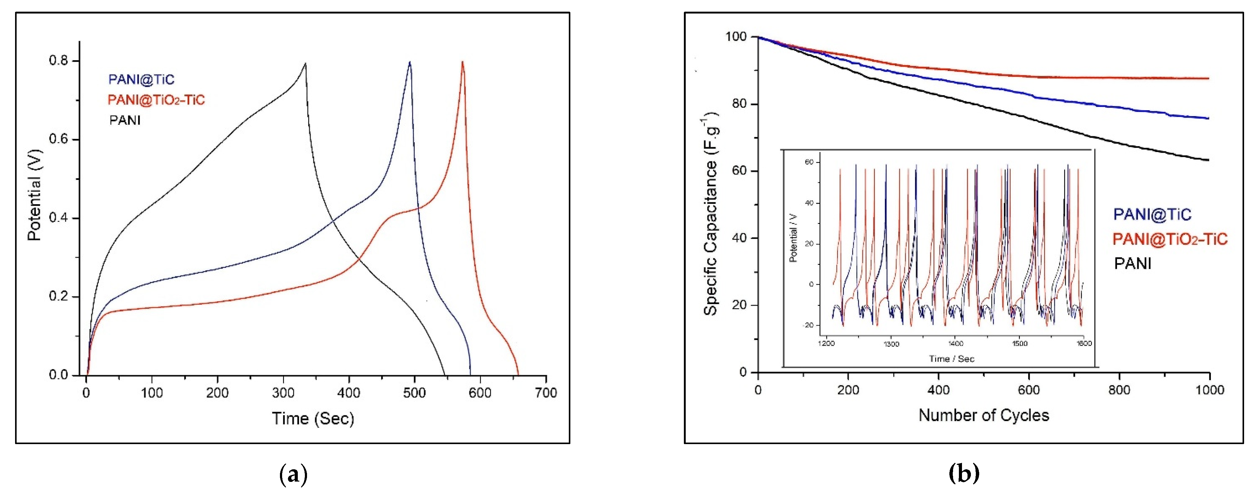
The cycling behavior is one of the most critical indices in the practical application of electrodes’ supercapacitors. The long-term stability of as-formed electrodes was examined by galvanostatic charge/discharge (GCD) [40], and the results are presented in Figure 8a. The executed GCD showed a potential range from 0.0 to 0.8 V at a current density of 1.5 A·g−1. Generally, the GCD curves of these samples have an asymmetric distorted triangular shape with an evident plateau due to the faradaic character of the prepared electrode [41]. The charging slopes of PANI@TiO2–TiC demonstrated a rapid rise in voltage from 0.0 V to 0.15 V, which was also due to the equivalent-series-resistance (ESR) followed by a flattening of the curve at approximately 0.15 V–0.27 V due to the oxidation from ES to PB, the major redox transition where energy is stored [33], pursued by another flattening of the curve at approximately 0.40 V to 0.45 V. A steep ascent in the curve to 0.8 V followed, and then it continuously declined. Accordingly, the high GCD time observed in this case compared to other samples illustrates the high charge storage capacity of the PANI@TiO2–TiC electrode. It can be clarified by the porous interconnected structural character of the PANI matrix and the synergy between TiO2 and TiC. Therefore, it is evident that the existence of the crystalline TiO2–TiC composite with new porosity could reinforce the hybrid material stability [42]. This result also proved that the PANI@TiO2–TiC has an excellent electrochemical reversibility.
Cycling stability (CS) is a critical factor for operational supercapacitors. Particularly, polymer-based supercapacitors frequently experience limited CS due to the polymer shrinking and swelling during its GCD process [16]. Figure 8b displays the samples’ CS performance at the current density of 1.5 A·g−1. We found that the capacitance retention of PANI is quickly fading with a growing number of cycles achieving 64.4% after 1500 cycles (Figure 8b [43]. Furthermore, the capacitance retention of PANI@TiO2–TiC (88.2%) is higher than that of PANI@TiC (76.8%), showing the beneficial impact of TiO2. In other words, the presence of the TiO2 in TiO2–TiC composite can play a key role in the enhancement of PANI’s electrochemical performance, suggesting the good cycling performance of the device, demonstrating its great application potential for energy storage systems.
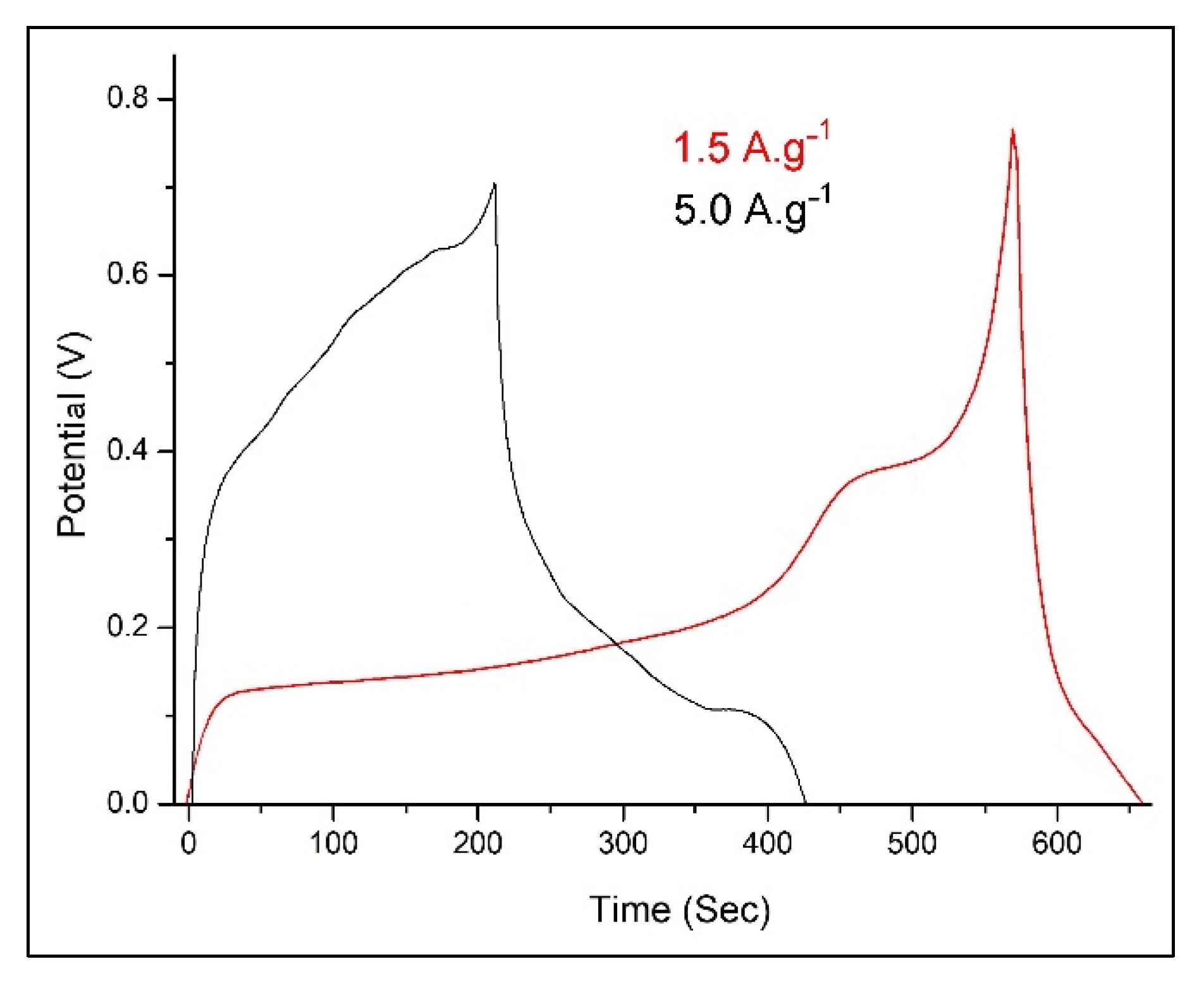
Figure 9 compares the GCD patterns of PANI@TiO2–TiC at current densities of 1.5 and 5.0 A·g−1. The specific capacitance Csp (F·g−1) from the electrode setup was calculated from CV and GCD by Equations (2) and (3):
Csp = 1 v m ( Δ V ) V a V c i V d V
Csp = 1 m ( Δ V / Δ t )
where Δ V is the applied potential window ( V a to V c ), v is the scan rate, m is mass of the active material and I (A) and Δ t (s) represent the current response and time during the discharging process.
The pattern shows that the Csp will diminish as the current density increases. Based on the GCD curves, the calculated Csp of the device reaches 105.8 F·g−1 at 0.5 A·g−1, and decreases by increasing at a high current density of 5.0 A·g−1 to 52.2 F·g−1.

4. Conclusions

Hybrid materials based on TiO2 and TiC were successfully prepared to support and enhance the stabilization of PANI. The resulting materials were analyzed by XPS, FTIR, XRD, UV–vis, SEM, TEM and TGA. Furthermore, the electrical conductivity and optical bandgap were tested as well. Interestingly, the PANI@TiO2–TiC shows fascinating electrochemical performance; the excellent electrochemical properties of this hybrid material can be attributed to the effect of covalent synergy between the TiO2–TiC composite and the PANI backbone. In addition, the results reveal that the hybrid material containing TiO2–TiC appears to have perfect stability because of its crystalline structure, which can be sustained for a long time during the GCD operation. As a consequence of better cycle stability (88.2% after 1500 cycles), the PANI@TiO2–TiC developed in our investigation appears to be a potential candidate for electrodes in supercapacitor applications.

Author Contributions

Conceptualization: H.B. and A.B.; methodology: H.B. and A.B.; software: I.M. and A.B.; validation: L.S. and A.B.; visualization: H.B., L.S. and I.M.; formal analysis: H.B. and A.B.; investigation: H.B., I.M. and A.B.; data curation: H.B.; writing—original draft preparation: H.B., L.S. and I.M.; writing—review and editing, all authors; visualization: L.S. and A.B.; supervision, A.B. All authors have read and agreed to the published version of the manuscript.

Funding

This research received no external funding.

Data Availability Statement

All data created in this study are presented in this paper.

Acknowledgments

The authors would like to express their gratitude to the Algerian DGRSDT-MESRS for their contributions to the scientific findings. The authors also would like to thank the researchers at IUMA, University of Alicante, Spain, for their useful support and cooperation. We would like to thank Ana-Katrina Büttner for language editing.

Conflicts of Interest

The authors declare no conflict of interest.

References

  1. Mahmoud, Z.H.; AL-Bayati, R.A.; Khadom, A.A. Synthesis and supercapacitor performance of polyaniline-titanium dioxide-samarium oxide (PANI/TiO2-Sm2O3) nanocomposite. Chem. Pap. 2022, 76, 1401–1412. [Google Scholar] [CrossRef]
  2. Abdel Maksoud, M.I.A.; Fahim, R.; Shalan, A. Advanced materials and technologies for supercapacitors used in energy conversion and storage: A review. Environ. Chem. Lett. 2021, 19, 375–439. [Google Scholar] [CrossRef]
  3. Banitaba, S.N.; Ehrmann, A. Application of Electrospun Nanofibers for Fabrication of Versatile and Highly Efficient Electrochemical Devices: A Review. Polymers 2021, 13, 1741. [Google Scholar] [CrossRef] [PubMed]
  4. Liang, J.; Zhao, H.; Yue, L.; Fan, G.; Li, T.; Lu, S.; Chen, G.; Gao, S.; Asiri, A.M.; Sun, X. Recent advances in electrospun nanofibers for supercapacitors. J. Mater. Chem. A 2020, 8, 16747–16789. [Google Scholar] [CrossRef]
  5. Yu, Z.; Tetard, L.; Zhai, L.; Thomas, J. Supercapacitor electrode materials: Nanostructures from 0 to 3 dimensions. Energy Environ. Sci. 2015, 8, 702. [Google Scholar] [CrossRef] [Green Version]
  6. De, B.; Banerjee, S.; Verma, K.D.; Pal, T.; Manna, P.K.; Kar, K.K. Carbon Nanofiber as Electrode Materials for Supercapacitors. In Handbook of Nanocomposite Supercapacitor Materials II; Kar, K., Ed.; Springer Series in Materials Science; Springer: Cham, Switzerland, 2020; Volume 302. [Google Scholar] [CrossRef]
  7. Wang, H.; Wang, W.; Wang, H.; Jin, X.; Niu, H.; Wang, H.; Zhou, H.; Lin, T. High Performance Supercapacitor Electrode Materials from Electrospun Carbon Nanofibers in Situ Activated by High Decomposition Temperature Polymer. ACS Appl. Energy Mater. 2018, 1, 431–439. [Google Scholar] [CrossRef]
  8. Storck, J.L.; Wortmann, M.; Brockhagen, B.; Frese, N.; Diestelhorst, E.; Grothe, T.; Hellert, C.; Ehrmann, A. Comparative Study of Metal Substrates for improved Carbonization of Electrospun PAN Nanofibers. Polymers 2022, 14, 721. [Google Scholar] [CrossRef]
  9. Storck, J.L.; Hellert, C.; Brockhagen, B.; Wortmann, M.; Diestelhorst, E.; Frese, N.; Grothe, T.; Ehrmann, A. Metallic Supports Accelerate Carbonization and Improve Morphological Stability of Polyacrylonitrile Nanofibers during Heat Treatment. Materials 2021, 14, 4686. [Google Scholar] [CrossRef]
  10. Storck, J.L.; Brockhagen, B.; Grothe, T.; Sabantina, L.; Kaltschmidt, B.; Tuvshinbayar, K.; Braun, L.; Tanzli, E.; Hütten, A.; Ehrmann, A. Stabilization and Carbonization of PAN Nanofiber Mats Electrospun on Metal Substrates. C 2021, 7, 12. [Google Scholar] [CrossRef]
  11. Yadav, D.; Amini, F.; Ehrmann, A. Recent advances in carbon nanofibers and their applications—A review. Eur. Polym. J. 2020, 138, 109963. [Google Scholar] [CrossRef]
  12. Ghebache, Z.; Safidine, Z.; Hamidouche, F. Effect of hematite on the energy storage performance of polyaniline/zeolite HY/α-Fe2O3 nanocomposite supercapacitor electrode. J. Inorg. Organomet. Polym. 2021, 31, 1153–1162. [Google Scholar] [CrossRef]
  13. Kedir, C.N.; Torres, D.S.; Jaime, A.F.Q.; Benyoucef, A.; Morallon, E. Hydrogels obtained from Aniline and Piperazine: Synthesis, characterization and their application in hybrid supercapacitors. J. Mol. Struct. 2022, 1248, 131445. [Google Scholar] [CrossRef]
  14. Bekhoukh, A.; Moulefera, I.; Sabantina, L.; Benyoucef, A. Development, Investigation, and Comparative Study of the Effects of Various Metal Oxides on Optical Electrochemical Properties Using a Doped PANI Matrix. Polymers 2021, 13, 3344. [Google Scholar] [CrossRef]
  15. Shaikh, S.; Lim, J.; Mane, R.; Zate, M.; Han, S.; Joo, O. Template-free electrochemical synthesis and electrochemical supercapacitors application of polyaniline nanobuds. J. Appl. Polym. Sci. 2013, 128, 3660–3664. [Google Scholar] [CrossRef]
  16. Rahman, S.U.; Röse, P.; Shah, A.U.H.A.; Krewer, U.; Bilal, S.; Farooq, S. Exploring the Functional Properties of Sodium Phytate Doped Polyaniline Nanofibers Modified FTO Electrodes for High-Performance Binder Free Symmetric Supercapacitors. Polymers 2021, 13, 2329. [Google Scholar] [CrossRef]
  17. Ren, K.; Liu, Z.; Wei, T. Recent developments of transition metal compounds-carbon hybrid electrodes for high energy/power supercapacitors. Nano-Micro Lett. 2021, 13, 129. [Google Scholar] [CrossRef]
  18. Hassan, A.; Abdulazeez, I.; Salawu, O. Electrochemical deposition and characterization of polyaniline-grafted graphene oxide on a glassy carbon electrode. SN Appl. Sci. 2020, 2, 1257. [Google Scholar] [CrossRef]
  19. Parveen, N.; Ansari, M.O.; Han, T.H.; Cho, M.H. Simple and rapid synthesis of ternary polyaniline/titanium oxide/graphene by simultaneous TiO2 generation and aniline oxidation as hybrid materials for supercapacitor applications. J. Solid State Electrochem. 2017, 21, 57–68. [Google Scholar] [CrossRef]
  20. Huv, Z.A.; Xie, Y.L.; Wang, Y.X.; Mo, L.P.; Yang, Y.Y.; Zhang, Z.Y. Polyaniline/SnO2 nanocomposite for supercapacitor applications. Mater. Chem. Phys. 2009, 114, 990–995. [Google Scholar] [CrossRef]
  21. Larios, L.M.; Mondragón, R.M.; Orozco, R.D.M.; García, U.P.; Alamilla, R.G. Electrochemically-assisted fabrication of titanium-dioxide/polyaniline nanocomposite films for the electroremediation of congo red in aqueous effluents. Synth. Met. 2020, 268, 16464. [Google Scholar] [CrossRef]
  22. Toumi, I.; Djelad, H.; Chouli, F.; Benyoucef, A. Synthesis of PANI@ZnO Hybrid Material and Evaluations in Adsorption of Congo Red and Methylene Blue Dyes: Structural Characterization and Adsorption Performance. J. Inorg. Organomet. Polym. Mater. 2022, 32, 112–121. [Google Scholar] [CrossRef]
  23. Zenasni, M.; Jaime, A.Q.; Benyoucef, A.; Benghalem, A. Synthesis and characterization of polymer/V2O5 composites based on poly(2-aminodiphenylamine). Polym. Compos. 2021, 42, 1064–1074. [Google Scholar] [CrossRef]
  24. Torres, D.S.; Sieben, J.M.; Castelló, D.L.; Amorós, D.C.; Morallón, E. Asymmetric hybrid capacitors based on activated carbon and activated carbon fibre–PANI electrodes. Electrochim. Acta 2013, 89, 326–333. [Google Scholar] [CrossRef] [Green Version]
  25. Torres, D.S.; Rosas, R.R.; Morallón, E.; Amorós, D.C. Strategies to Enhance the Performance of Electrochemical Capacitors Based on Carbon Materials. Front. Mater. 2019, 6, 115. [Google Scholar] [CrossRef]
  26. Jasna, M.; Pillai, M.M.; Abhilash, A.; Midhun, P.S.; Jayalekshmi, S.; Jayaraj, M.K. Polyaniline wrapped carbon nanotube/exfoliated MoS2 nanosheet composite as a promising electrode for high power supercapacitors. Carbon Trends 2022, 7, 100154. [Google Scholar] [CrossRef]
  27. Madhab, B.; Gupta, C.; Maji, P.; Pradip, K. Facile One-Pot Synthesis of Graphene Oxide by Sonication Assisted Mechanochemical Approach and Its Surface Chemistry. J. Nanosci. Nanotechnol. 2018, 18, 902–912. [Google Scholar] [CrossRef]
  28. Yang, N.; Zhai, J.; Wang, D.; Chen, Y.; Jiang, L. Two-dimensional graphene bridges enhanced photoinduced charge transport in dye-sensitized solar cells. ACS Nano 2010, 4, 887–894. [Google Scholar] [CrossRef]
  29. Gong, Y.; Tu, R.; Goto, T. High-speed deposition of titanium carbide coatings by laser-assisted metal–organic CVD. Mater. Res. Bull. 2013, 48, 2766–2770. [Google Scholar] [CrossRef]
  30. El Mel, A.A.; Angleraud, B.; Gautron, E.; Granier, A.; Tessier, P.Y. Microstructure and composition of TiC/a-C:H nanocomposite thin films deposited by a hybrid IPVD/PECVD process. Surf. Coat. Technol. 2010, 204, 1880–1883. [Google Scholar] [CrossRef]
  31. Natu, V.; Benchakar, M.; Canaff, C.; Habrioux, A.; Célérier, S.; Barsoum, M. A critical analysis of the X-ray photoelectron spectra of Ti3C2Tz MXenes. Matter 2021, 4, 1224–1251. [Google Scholar] [CrossRef]
  32. Li, Y.; Xia, Z.; Gong, Q.; Liu, X.; Yang, Y.; Chen, C.; Qian, C. Green Synthesis of Free-Standing Cellulose/Graphene Oxide/Polyaniline Aerogel Electrode for High-Performance Flexible All-Solid-State Supercapacitors. Nanomaterials 2020, 10, 1546. [Google Scholar] [CrossRef] [PubMed]
  33. Lin, T.; Liu, W.; Yan, B.; Li, J.; Lin, Y.; Zhao, Y.; Shi, Z.; Chen, S. Self-Assembled Polyaniline/Ti3C2Tx Nanocomposites for High-Performance Electrochromic Films. Nanomaterials 2021, 11, 2956. [Google Scholar] [CrossRef] [PubMed]
  34. Guo, Y.; He, D.; Xia, S.; Xie, X.; Gao, X.; Zhang, Q. Preparation of a Novel Nanocomposite of Polyaniline Core Decorated with Anatase-TiO2 Nanoparticles in Ionic Liquid/Water Microemulsion. J. Nanomater. 2012, 2012, 8. [Google Scholar] [CrossRef] [Green Version]
  35. Lv, P.; Tang, X.; Zheng, R.; Ma, X.; Yu, K.; Wei, W. Graphene/polyaniline aerogel with superelasticity and high capacitance as highly compression-tolerant supercapacitor electrode. Nanoscale Res. Lett. 2017, 12, 630. [Google Scholar] [CrossRef] [Green Version]
  36. Maaza, L.; Djafri, F.; Belmokhtar, A.; Benyoucef, A. Evaluation of the influence of Al2O3 nanoparticles on the thermal stability and optical and electrochemical properties of PANI-derived matrix reinforced conducting polymer composites. J. Phys. Chem. Solids 2021, 152, 109970. [Google Scholar] [CrossRef]
  37. You, Y.; Wang, Y.; Tu, L.; Tong, L.; Wei, R.; Liu, X. Interface Modulation of Core-Shell Structured BaTiO3@polyaniline for Novel Dielectric Materials from Its Nanocomposite with Polyarylene Ether Nitrile. Polymers 2018, 10, 1378. [Google Scholar] [CrossRef] [Green Version]
  38. Ibrahim, K.A. Synthesis and characterization of polyaniline and poly(aniline-co-o-nitroaniline) using vibrational spectroscopy. Arab. J. Chem. 2017, 10, 2668–2674. [Google Scholar] [CrossRef] [Green Version]
  39. Abutalib, M.M.; Rajeh, A. Preparation and characterization of polyaniline/sodium alginate doped TiO2 nanoparticles with promising mechanical and electrical properties and antimicrobial activity for food packaging applications. J. Mater. Sci. Mater. Electron. 2020, 31, 9430–9442. [Google Scholar] [CrossRef]
  40. Guan, L.; Yu, L.; Chen, G.Z. Capacitive and non-capacitive faradaic charge storage. Electrochim. Acta 2016, 206, 464–478. [Google Scholar] [CrossRef]
  41. Saliu, O.D.; Mamo, M.; Ndungu, P.; Ramontja, J. Starch built TiO2 nanoarchitecture with mixed anatase and rutile phase for high energy density supercapacitor electrode. J. Energy Storage 2022, 49, 104155. [Google Scholar] [CrossRef]
  42. Geng, X.; Yi, R.; Lin, X.; Liu, C.; Sun, Y.; Zhao, Y.; Li, Y.; Mitrovic, I.; Liu, R.; Yang, L.; et al. A high conductive TiC–TiO2/SWCNT/S composite with effective polysulfides adsorption for high performance Li–S batteries. J. Alloys Compd. 2021, 851, 156793. [Google Scholar] [CrossRef]
  43. Pal, R.; Goyal, S.L.; Rawal, I.; Gupta, A.K.; Ruchi. Efficient energy storage performance of electrochemical supercapacitors based on polyaniline/graphene nanocomposite electrodes. J. Phys. Chem. Solids 2021, 154, 110057. [Google Scholar] [CrossRef]
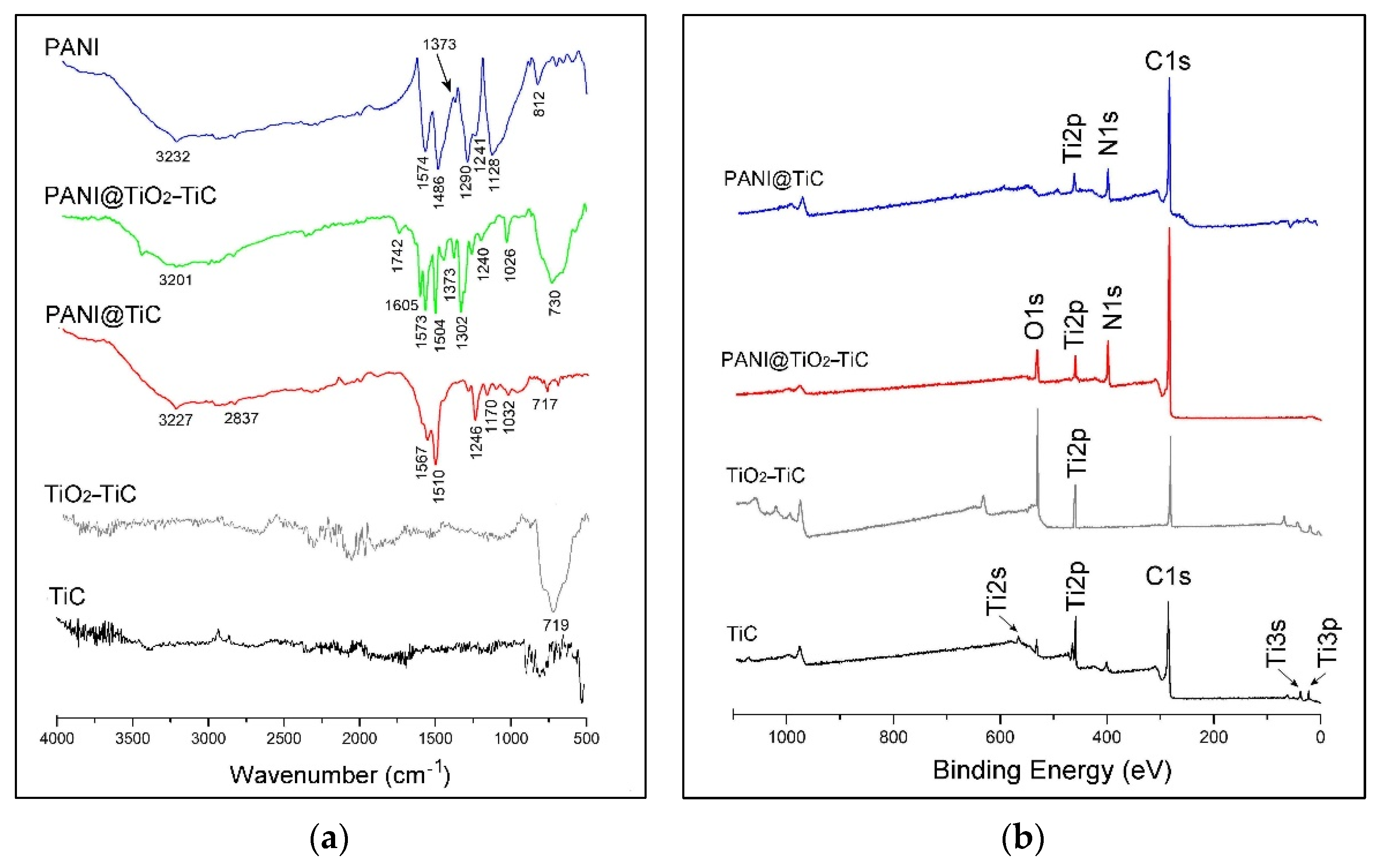
Figure 1. (a) FTIR analysis; and (b) survey XPS spectra of samples.
Fibers 10 00046 g001
Figure 2. XPS spectra for Ti2p signals of: (a) TiC and (b) TiO2–TiC.
Fibers 10 00046 g002
Figure 3. XPS spectral: (a) C1s of PANI@TiC; (b) C1s of PANI@TiO2–TiC; (c) N1s of PANI@TiC; and (d) N1s of PANI@TiO2–TiC.
Fibers 10 00046 g003
Figure 4. X-ray diffraction (XRD) patterns of the samples.
Fibers 10 00046 g004
Figure 5. Transmission electron microscopy (TEM) images of: (a) TiC; (b) PANI@TiC; (c) TiO2–TiC; and (d) PANI@TiO2–TiC.
Fibers 10 00046 g005
Figure 6. Scanning electron microscope (SEM) images of: (a) TiC; (b) PANI@TiC; (c) TiO2–TiC; and (d) PANI@TiO2–TiC. Scale bar indicates 5 µm.
Fibers 10 00046 g006
Figure 7. (a) Thermogravimetric analysis (TGA) curves; (b) UV–vis spectroscopy absorption spectra; (c) Tauc plots; and (d) samples’ responses to cyclic voltammetry.
Fibers 10 00046 g007
Figure 8. (a) Galvanostatic charge/discharge (GCD) response; (b) the galvanostatic cycling curve of materials electrode (1500 GCD cycles). The inset of the galvanostatic cycling data in (b) was collected at 1.5 A·g−1.
Fibers 10 00046 g008
Figure 9. Galvanostatic charge/discharge (GCD) response of PANI@TiO2–TiC at different current densities.
Fibers 10 00046 g009
Table 1. Summary of the XPS binding energy values (eV) obtained for hybrid materials.
Binding Energy/eVPANI@TiCPANI@TiO2–TiCAssignments
C1s282.14282.17Ti–C
284.28284.64C=C; C–C
286.01285.70C–N
//286.91C=N+; C=N
N1s//398.07–N=
398.98399.11–NH2, –NH–
400.36//–NH+
Ti2p455.36//Ti2p3/2 (Ti–C)
467.92//Ti2p1/2 (Ti–C)
//458.82Ti2p3/2 (Ti–O2)
//464.65Ti2p1/2 (Ti–O2)
Table 2. The atomic percentage (%) of synthesized hybrid materials.
MaterialsC1sN1sO1sTi2pDL*FD**
PANI@TiC80.0410.892.086.510.490.53
PANI@TiO2–TiC69.5211.4010.488.140.740.08
(DL*) Doping   Level = high   binding   energy   band total   band   area ; (FD**) Flaws   Density = lowest   binding   energy   band   of   N 1 s total   band   area   of   N 1 s .
Table 3. Optical bandgap (Eg) and Redox peak of the synthesized samples.
MaterialsRedox Peaks/VEg/eV
Eox1/red1ΔEp1Eox2/red2ΔEp2
PANI0.49/0.290.200.94/0.820.122.64
PANI@TiC0.32/0.280.040.64/0.540.102.72
PANI@TiO2–TiC0.38/0.310.070.67/0.510.162.40
Publisher’s Note: MDPI stays neutral with regard to jurisdictional claims in published maps and institutional affiliations.