Article

Bifunctional TiO2/AlZr Thin Films on Steel Substrate Combining Corrosion Resistance and Photocatalytic Properties

by
Caroline Villardi de Oliveira
1,2,3,*,
Akram Alhussein
1,2,
Juan Creus
4,
Frédéric Schuster
5,
Michel L. Schlegel
5,
Zhili Dong
6,
Carmen Jiménez
3 and
Frédéric Sanchette
1,2
1
ICD-LASMIS, Université de Technologie de Troyes CNRS, Antenne de Nogent, Pôle Technologique de Sud Champagne, 52800 Nogent, France
2
NICCI, LRC CEA-ICD LASMIS, UTT, Antenne de Nogent, Pôle Technologique de Sud Champagne, 52800 Nogent, France
3
Univ. Grenoble Alpes, CNRS, Grenoble INP, LMGP, 38000 Grenoble, France
4
LaSIE UMR 7356 CNRS, La Rochelle Université, Avenue Michel Crépeau, 17042 La Rochelle, France
5
CEA, PTCMP, Centre de Saclay, 91191 Gif-sur-Yvette, France
6
School of Materials Science and Engineering, Nanyang Technological University, Singapore 639798, Singapore
*
Author to whom correspondence should be addressed.
Coatings 2019, 9(9), 564; https://doi.org/10.3390/coatings9090564
Submission received: 26 June 2019 / Revised: 29 August 2019 / Accepted: 30 August 2019 / Published: 3 September 2019
(This article belongs to the Special Issue Magnetron Sputtering Deposited Thin Films and Its Applications)

Abstract

:
A novel multi-functional bilayer coating combining an anti-corrosion Al–Zr (4 at.% Zr) underlayer and an anti-biofouling TiO2 top layer was deposited on high-speed steel (HSS) substrates. Al–Zr (4 at.% Zr) film, deposited by DC magnetron sputtering, which is a single phased supersaturated solid solution of Zr in Al, is used to provide sacrificial corrosion resistance of steels and TiO2 is added as a top layer to induce photocatalytic activity and hydrophilic behavior which can generate antifouling properties in order to slow down the biofouling process. The top TiO2 films, deposited at 550 °C by AACVD (aerosol-assisted chemical vapor deposition), consisting of anatase TiO2 microflowers physically attached to the TiO2 thin films present a high decomposition rate of Orange G dye (780 × 10−10 mol L−1·min−1). The enhanced photocatalytic performance is associated with the rough network and the presence of TiO2 microflowers capable of supporting the enhanced loading of organic contaminants onto the film surface. Electrochemical tests in saline solution have revealed that bilayer films provide cathodic protection for the steel substrate. The Al–Zr/TiO2 bilayer presents a lower corrosion current density of 4.01 × 10⁻⁷ A/cm2 and a corrosion potential of −0.61 V vs. Ag/AgCl, offering good protection through the preferential oxidation of the bilayer and an increased pitting resistance. The proposed functionalized coating combining anticorrosion and photocatalytic properties is a promising candidate for an anti-fouling system in sea water.

Graphical Abstract

1. Introduction

Marine biofouling is the growth and accumulation of micro and macro-organisms on wet surfaces in saline environments and it is a global problem disturbing aquatic industries. Biofouling can reduce the speed of ships, boost fuel consumption, and stimulate corrosion, which provokes mechanical deterioration of static structures [1]. Biofouling takes place on almost all surfaces starting with the attachment of organic molecules pursued by adherence of bacteria, diatoms, and microalgae to create a biofilm that is followed by the adhesion of macro-organisms, such as barnacles, bivalves, and macro-algae [2,3]. Priyanka et al. [4] have demonstrated that photocatalytic material can prevent biofouling by generating reactive oxygen species under visible light irradiation, which in a marine environment can lead to cell death in a variety of contaminants [5,6,7].
The corrosion of metals in natural seawater is a consequence of interactions between metal, living organisms, and seawater composition [8]. When a metal is submerged into seawater, corrosion, and biofouling take place on almost the same time proportions [9]. This is usually pursued by the development of biofilm within days after submersion [10] and after a continued exposure, macrobiota like invertebrate larvae may combine with the biofilm and settle on the surface [11].
To solve this problem, we address two functional properties: photocatalysis, which is related to the surface properties to avoid the initial step of attachment, and corrosion, to protect the steel used in the mechanical system. Cathodic protection systems might be able to polarize all underwater steel structures to a potential between −800 and −1100 mV vs. the Ag/AgCl/seawater reference electrode, and to preserve the potential in this interval throughout the life of the structures [12].
Titanium is the most abundant transition metal on earth and its metal oxide TiO2 is a wide band-gap semiconductor with high chemical stability, low-cost, non-toxicity, and high photoelectric conversion productivity. In recent years, titanium dioxide (TiO2) has been extensively investigated for its remarkable UV-photocatalytic and self-cleaning properties, which, for example, can promote the decomposition of organics present into harmless products under UV light irradiation [13]. The extent of the photo-activity depends on an extensive variety of properties, such as morphology, crystallinity, and surface area.
TiO2 possesses unique electronic properties combined with the possibility of easy nanostructuring and chemical stability. Typically, when the surface of a semiconductor material is exposed to photons having energy greater than or equal to its band-gap energy, photo-electrons e, and photo-holes h+ are produced [14]. As the photocatalyst is simultaneously capable of adsorbing reactants and absorbing photons, the photogenerated e and h+ are thus capable of reducing and oxidizing pollutants adsorbed on the photocatalyst’s surface [15].
Nano and microstructures play an important role in enhancing the performance of devices, mainly due to the increase of the specific surface area [16] as for photocatalyzed reactions. TiO2 structures that have a high mesoporosity and surface area are mostly attractive, as these increase the efficiency of photocatalysis phenomena taking place at the interfaces. Morphology, structure, phase, and dimensionality adjust physical and chemical properties of the TiO2 nanostructures. Tian [16] demonstrated that 3D flower-like TiO2 showed the highest UV light absorption when integrated in dye-sensitized solar cells (DSSC) compared to nanospheres and nanorod structures; even the photocatalytic activity (97% degradation efficiency) for flowers was higher than for spheres or rod-like structures (60% and 55%, respectively). These are mainly due to the fact that 3D hierarchical flower-like structures are easily accessible to light and reactants thanks to an increased effective surface area.
Zhu et al. [17] also demonstrated that anatase TiO2 materials having flowerlike morphologies with a high specific surface area presented an excellent performance when tested in photodegradation of methylene blue.
Aerosol assisted metal–organic chemical vapor deposition (AA-MOCVD) has been already demonstrated to deposit TiO2 films having hierarchical TiO2 microflowers. Biswas et al. [18] showed that AA-MOCVD working at atmospheric pressure allows the synthesis of TiO2 microflowers physically adhered to a thin film of TiO2. We propose using these microstructures as a TiO2 active layer in the bilayer coating.
Aluminum and its alloys are extensively used in many industrial applications as long as their open circuit potential is more negative than that of steel implying its use as sacrificial materials for the protection of steel. Aluminum-based alloy coatings have been extensively studied and proposed as potential candidates for galvanic corrosion protection of mechanical steel parts [19,20,21,22,23,24,25]. For instance, transition metals (TM) can be added to mechanically reinforce aluminum. The low solubility of TM in aluminum allows the deposition of extended supersaturated solid solution of TM in aluminum. Moreover, a good thermal stability due to the low diffusivity of TM in aluminum is expected. Addition of high content of TM conducts typically to high mechanical properties compared to pure aluminum but with the detriment of sacrificial properties [26,27]. The ideal solution in terms of protection of steels agrees to a compromise between mechanical and corrosion properties.
Zirconium is a transition metal, which is known as a great grain refiner in traditional aluminum alloys [28]. It boosts mechanical properties [28] and improves considerably the corrosion resistance in deaerated borate-boric acid solution containing Cl [29]. Different to traditional methods where the Zr solid solubility is very low, non-equilibrium processing methods like rapid solidification [30], mechanical alloying [31], and sputtering technique [29,32,33] offer the possibility to achieve a supersaturated single solid solution with high Zr contents. In order to improve the efficiency of aluminum anodes, they are typically alloyed with other elements to encourage depassivation (breakdown of the oxide film) and/or shift the operating potential of the metal towards a more negative direction. Addition of alloying elements like Zr is characterized by an increase of the corrosion potential. Moreover, in the same time, increasing Zr content in Al allows one to lower the corrosion current density, which is associated with better corrosion resistance [34]. Al–Zr with 4 at.% Zr appears as the best compromise between the good corrosion behavior and the sacrificial character of the coating.
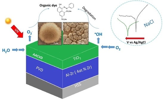
In this work, we propose a bilayer film consisting of a sputtered deposited crystalline Al–Zr film containing 4 at.% of Zirconium with a thickness of about 3 µm as a sacrificial anode coating, and a TiO2 film deposited by the Aerosol CVD technique responsible for enhanced photocatalytic properties. The proposed functionalized coating is a promising candidate for an anti-fouling system in sea water.

2. Materials and Methods

2.1. Synthesis and Deposition Process

High speed steel (HSS) substrates with 30 mm in diameter and 1 mm thick were polished having a roughness average Ra equal to 47 nm. Substrates were degreased, rinsed with ethanol, and dried before the deposition. Aluminum–Zirconium alloy films (2.7 µm thick) were co-deposited using standard DC magnetron sputtering (3-kW-SAIREM pulsed DC supply, equipped with a fast arc detector able to cut off micro-arcs within 1–2 µs, Dephis, Etupes, France) of pure metallic Al and Zr targets at floating temperature. The unheated substrates (the floating temperature is below 70 °C) were fixed on a rotating substrate-holder, at floating potential, ensuring a good homogeneity in thickness and composition of coatings. The sputtering chamber was pumped down via a mechanical pump and a turbo-molecular pump permitting a base vacuum of 5 × 10⁻⁴ Pa. The substrates surfaces were cleaned by an argon plasma etching at 200 W for 30 min to remove impurities, surface oxides and contaminates just before the deposition. The distance between targets and substrate-holder (8 cm), the argon flow rate (20 sccm) and the working pressure (PAr = 0.32 Pa) were kept constant. Constant Zr content was ensured by fixing the Aluminum discharge current at 2 A and zirconium discharge current at 0.22 A. With these conditions, the deposition rate is about 1 μm/h and the alloy composition is 4 at.% Zr. This composition led to the best compromise between intrinsic corrosion resistance, sacrificial character/steels, and mechanical reinforcement. Increasing Zr content in Al leads to a decrease in the mean grain size, which enhance its hardness. At the same time, the intrinsic corrosion resistance of these Al–Zr alloys is higher. However, above 4 at.% or 5 at.% of Zr in Al, these alloys become nobler than the steel substrate and the sacrificial character is lost [34].
TiO2 films deposition were performed by AA-MOCVD (aerosol-assisted metal organic chemical vapor deposition) using a custom-designed and home-made reactor working at atmospheric pressure [35]. Titanium (IV) oxide bisacetylacetonate (C10H14O5Ti, Strem Chemicals, Newburyport, MA, USA) was used as precursor and ethanol as solvent. The precursor was selected for its low-toxicity, good stability at room temperature, easy handling, and low cost. The titanium precursor was dissolved in ethanol with a concentration of 0.03 mol L−1. The aerosol was generated by a piezoelectric ceramic by adjusting the frequency and power (800 kHz, 60 W), forming a mist on top of the precursor solution. This mist was transported by air flow into the deposition chamber. An oxidizing gas flow was mixed to the precursor flow consisting in 6 L min−1 of air (12% of O2). Within these conditions, the solution consumption was around 3 mL min−1. A solution consumption between 3 and 4 mL min−1 allows the formation of hierarchical microflowers. However, less than 3 mL min−1 microflowers are not developed. The deposition temperature was varied between 500 and 550 °C for a deposition time of 40 min. The substrates used in this work were high-speed steel or Al–Zr coated high-speed steel.

2.2. Characterization

2.2.1. Film Morphology, Surface Topography, and Thickness

Film morphology was observed by scanning electron microscopy (SEM) and composition by EDS microanalysis using an FEI Quanta 250 field-emission scanning electron microscope (FESEM, Hillsboro, OR, USA) for high-resolution images. Surface roughness profiles of samples were characterized using a Form Talysurf 50 (Taylor Hobson Co Ltd., Leicester, UK) surface Profilometer and measured 25 mm crossing the center along the surface of the sample. For these measurements, the pre-race length used was 0.30 mm, the spacing (y) was 0.1 mm, the measuring speed was 1 mm/s and the number of points was 5000. As described in ASME B46.1, Ra is the arithmetic average of the absolute values of the profile height deviations from the mean line, recorded within the evaluation length. Ra is the average of a set of individual measurements of the peaks and troughs of a given surface [36]. Thicknesses, which are evaluated from bright field images by TEM (JEOL JEM-2100F, Tokyo, Japan), are 2.7 μm and 1.4 μm for Al–Zr and TiO2, respectively.

2.2.2. Structural Characterization

The crystallinity and phase identification of the samples were studied by X-ray diffraction (XRD) in θ–2θ scanning mode using a Bragg–Brentano configuration between 10° and 80° at 0.011° intervals with an acquisition time of 2 s, using a Bruker D8 Advance diffractometer (Billerica, MA, USA) with monochromatic Cu Kα1 radiation (λ = 0.15406 nm).
The crystallite size was determined using the Scherer’s formula based on the FWHM (full width at half maximum) of (101), (200), and (211) anatase peaks in XRD patterns:
Dp = (K × λ)/(β × cosθ)
where D is the crystallite size in nanometers, λCu = 0.15418 nm is the X-ray wavelength, θ is the diffraction angle of the (101), (200), and (211) peaks and β is defined as the peak width of the diffraction peak profile at half maximum height resulting from small crystallite size in radians and K is a constant related to crystallite shape. A value of 0.9 was assigned to the Scherrer’s constant K.
Raman spectra were collected using a Jobin-Yvon/Horiba LabRam multichannel spectrometer (Kyoto, Japan) equipped with a liquid N2 cooled CCD detector. Experiments were conducted in the micro-Raman mode at room temperature in a backscattering geometry. The 514.5 nm line of an Ar+ laser (2.6 mW) was focused giving a spot size of about 1 μm. The recorded spectra were calibrated using Si spectra at room temperatures. The integration times were adjusted in order to have a high signal-to-noise ratio.
Transmission electron microscopy (TEM) images were collected using JEOL JEM-2100F with an accelerating voltage of 200 kV. The point resolution of the TEM is 0.19 nm. TEM specimens were prepared by breaking the coating surface layers using a diamond knife and putting the obtained fine particles onto TEM copper grids coated with holey carbon films.

2.2.3. Photocatalytic Characterization

The photocatalytic activity of TiO2 films was evaluated by measuring the decomposition rate of aqueous Orange G solutions (C = 5 × 10⁻⁵ M) using a UV–VIS Perkin Elmer Lambda 35 (Waltham, MA, USA). Absorbance spectra were acquired using a wavelength range from 400 to 600 nm. The photocatalytic performance of TiO2/Al–Zr bilayer films were carried out by degrading orange G aqueous solution under UV irradiation. The degradation reaction was carried out in a beaker positioned on a support allowing it to be held at 20 mm above the UV lamps. The whole is placed in an oven regulated in humidity (RH = 40%) and temperature (T = 20 °C) under the UV light of three UV lamps (Philips PLS 11 W) emitting at 365 nm, chosen because absorption of Orange G is negligible at this wavelength. The surface area of the sample exposed to irradiation was 7.06 cm2 and the radiance was 5 mW/cm2. The volume of initial Orange G aqueous solution was 50 mL. In order to homogenize the solution and to maintain constant adsorption/desorption conditions during UV exposure, the solution is stirred constantly during irradiation via a magnetic bar and a magnetic stirrer set at 500 rpm.
For a better comparison, we analyzed the kinetic linear simulation of degradation of Orange G, following the pseudo-first-order kinetics model due to the low initial Orange G concentration. The equation is described as [37]:
r = −dC/dt = kc(KadsC/(1 + kC)
where r is the degradation rate of the reactant (mol L−1 h−1), C is the concentration of reactant (mol L−1), t is the irradiation time, kc is the kinetic constant of the reaction, and Kads is the adsorption constant of the reactant. When the initial concentration is very low, the equation can be simplified to an apparent first-order model [37]:
ln(C0/C) = kc·Kads·t = Kappt
where C0 is the concentration of Orange G after the adsorption–desorption equilibrium, Kapp is the apparent first-order rate constant (h−1).
The constant k was used to compare the photocatalytic activities of the different samples. k describes an apparent kinetic constant of the system.

2.2.4. Electrochemical Tests

The electrochemical measurements were carried out in an aerated and stirred chlorine solution (5 wt.% NaCl solution) using an Autolab potentiostat driven by NOVA 2.0 software (Metrohm Autolab, Utrecht, Netherlands). A total of 3 measurements were performed for each sample. The pH of the solution was adjusted to 6 by the addition of 0.5 M HCl solution and each measurement was performed at room temperature. The potentials were referenced against an Ag/AgCl electrode and the counter electrode was a large platinum grid. The effective area of working electrode was 1.327 cm2. The polarisation curves were recorded in the potential range of ±150 mV around the open circuit potential (OCP) at a scan rate of 0.2 mV/s after 1 h of immersion in the saline solution. The corrosion potential Ecorr and corrosion current density Icorr were estimated from the cross-over point of the two tangents drawn on a linear portion of anodic and cathodic polarization curves. The evolution of open circuit potential was recorded during 1 h.

2.2.5. Coating Hydrophilicity

The hydrophilicity was evaluated by measuring the contact angle and surface energy of water droplets with a goniometer KRÜSS G10 (Hamburg, Germany). A droplet of distilled water with 0.5 µL volume was placed on its surface and the first contact angle was measured immediately. The contact angle was measured before and after the incidence of light in the UV-C region used for the evaluation of photocatalytic activities. Each value was an average of 3 measurements on different areas of the sample surface.

3. Results and Discussion

Polished high-speed steel (HSS) substrates were systematically covered with a previously optimized atomic composition Al–Zr coating [34]. Then, TiO2 films were deposited at different temperatures to determine the deposition conditions allowing the formation of flower-like microstructures, as described by Biswas et al. [18] In this previous study, they proved that AACVD (aerosol-assisted chemical vapor deposition) allows the deposition of dense TiO2 layers containing hierarchical microflowers crystallized in the anatase phase and presenting a milky texture as a result of light scattering from the flowers. It was demonstrated that by adjusting the deposition conditions, it is possible to obtain TiO2 films containing TiO2 hierarchical microflowers on the surface [18]. Nevertheless, the formation of these hierarchical structures is obtained for a limited deposition condition window. These conditions are often reactor dependent and have to be tuned. To find the optimal deposition conditions, the solution concentration and solution feeding rate were fixed and deposition temperature varied between 500 and 550 °C. A feeding rate between 3 and 4 mL/min allows the formation of microflowers.

3.1. Morphology of Al–Zr and TiO2 Films

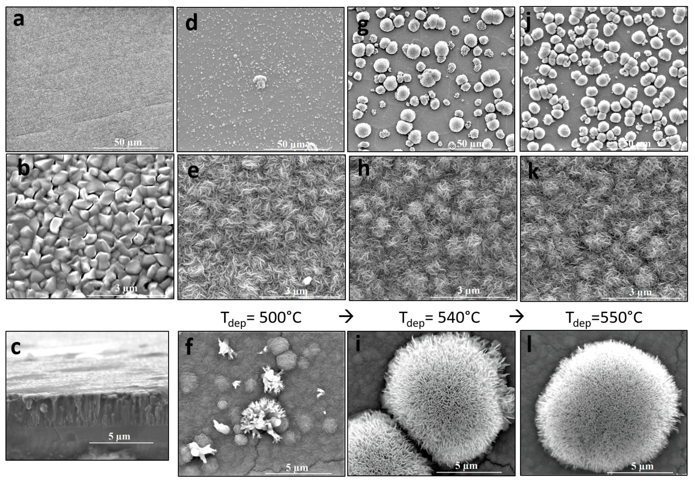
The morphology of as-deposited Al–Zr films observed by SEM is shown in Figure 1a,b for low and high magnifications conditions in the upper and lower pictures, respectively, and in cross-section represented in Figure 1c. For low Zr contents like in our case and in our deposition conditions, the coatings grow with a columnar morphology forming big grains of around 500 nm of diameter. The Al–Zr coating thickness is 2.7 µm. The hardness of this film is 2.3 Gpa and Young’s modulus E is 94.46 Gpa. This material is susceptible to limit cracking from the top layer (Figure 1f) to the Al–Zr/steel interface. Nanoindentation experiment was impossible on the TiO2 top layer surface because of its particular morphology.
When TiO2 is deposited by AACVD as a second layer on the Al–Zr coating, two kinds of features appear. On one hand, a film consisting in small needle-like (dendritic microspheres) grains of 50 nm covered the Al–Zr grains in a very conformal way. This morphology can be observed in Figure 1e,h,k), for the three deposition temperatures used. The Al–Zr grains can be still identified even if TiO2 film thicknesses are around 1.4 µm. On the other hand, microflowers started to grow for deposition temperatures higher than 500 °C. At 500 °C, represented in Figure 1d–f, some sparse flowers can be observed but much smaller than those shown in Figure 1g–l) for films deposited at 540 and 550 °C, respectively. For films deposited at 540 and 550 °C, the flowers density increases. Flowers having an average diameter of about 7 µm can be described by a homocentric association of TiO2 nanopetals forming a corolla as if growing from the receptacle of a flower. The main characteristics of these microstructure is that petals have a nanometric thickness (~5 nm) and are formed by nanocrystal of anatase phase as we show in the next section.
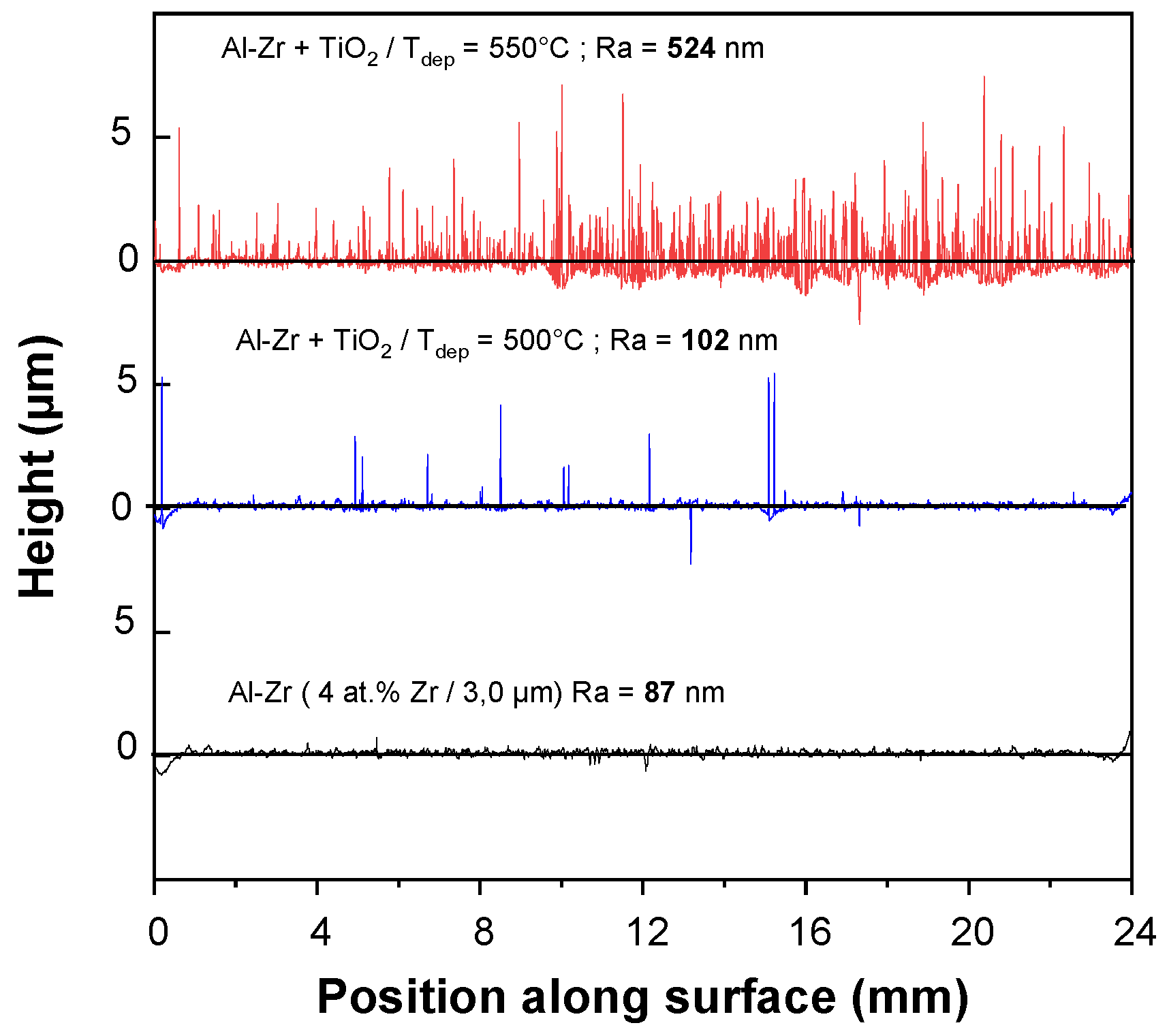
Figure 2 presents the surface roughness profiles for the HSS/Al–Zr sample and for the TiO2/AlZr bilayer sample deposited at 500 and 550 °C. Ra values were measured using contact mode, where the measuring instrument was in direct contact with the surface.
Al–Zr monolayer film presents a rough surface with a Ra value of 87 nm. The roughness increases when TiO2 layer is added and also when the deposition temperature increases. The TiO2 film deposited at 500 °C, reproduces the Al–Zr baseline, with sparse peaks corresponding to the presence of microflowers. For TiO2 deposited at 540 °C, the density of microflowers is so high that provokes a very high roughness with an average Ra = 524 nm. The highest variation in height corresponds to structures of 7 µm, which are associated to the height of the biggest microflowers dispersed at the top of the layer.

3.2. Structure Analysis

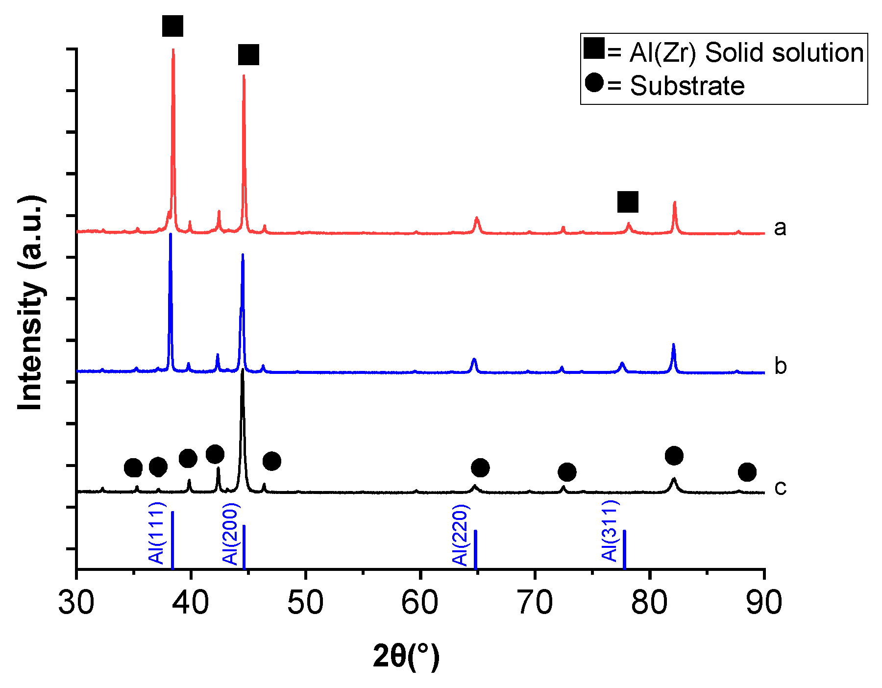
The structure of Al–Zr (4 at.% Zr) films was studied by XRD for the as deposited and also after annealing at 500 °C in air. The annealing was performed in order to check the Al–Zr stability during the TiO2 deposition by AACVD.
Figure 3 shows the XRD patterns for the HSS substrate together with the Al–Zr (4 at.% Zr) films deposited by DC magnetron sputtering in as-deposited conditions and after thermal annealing. HSS substrate is characterized by a large amount of Fe–Cr phase. The diffraction peaks in the diffractogram corresponding to as-deposited Al–Zr film can be correlated to an fcc structure indicating the growth of a supersaturated solid solution of Zr in Al without the presence of any parasitic phase.
When comparing the XRD patterns of Al–Zr film as deposited and annealed in air at 500 °C, no main changes are found; in both cases, the diffraction peaks of aluminum, with a very high intensity of (111) diffraction peak at 38° is obtained, suggesting the presence of α-Al solid solution.
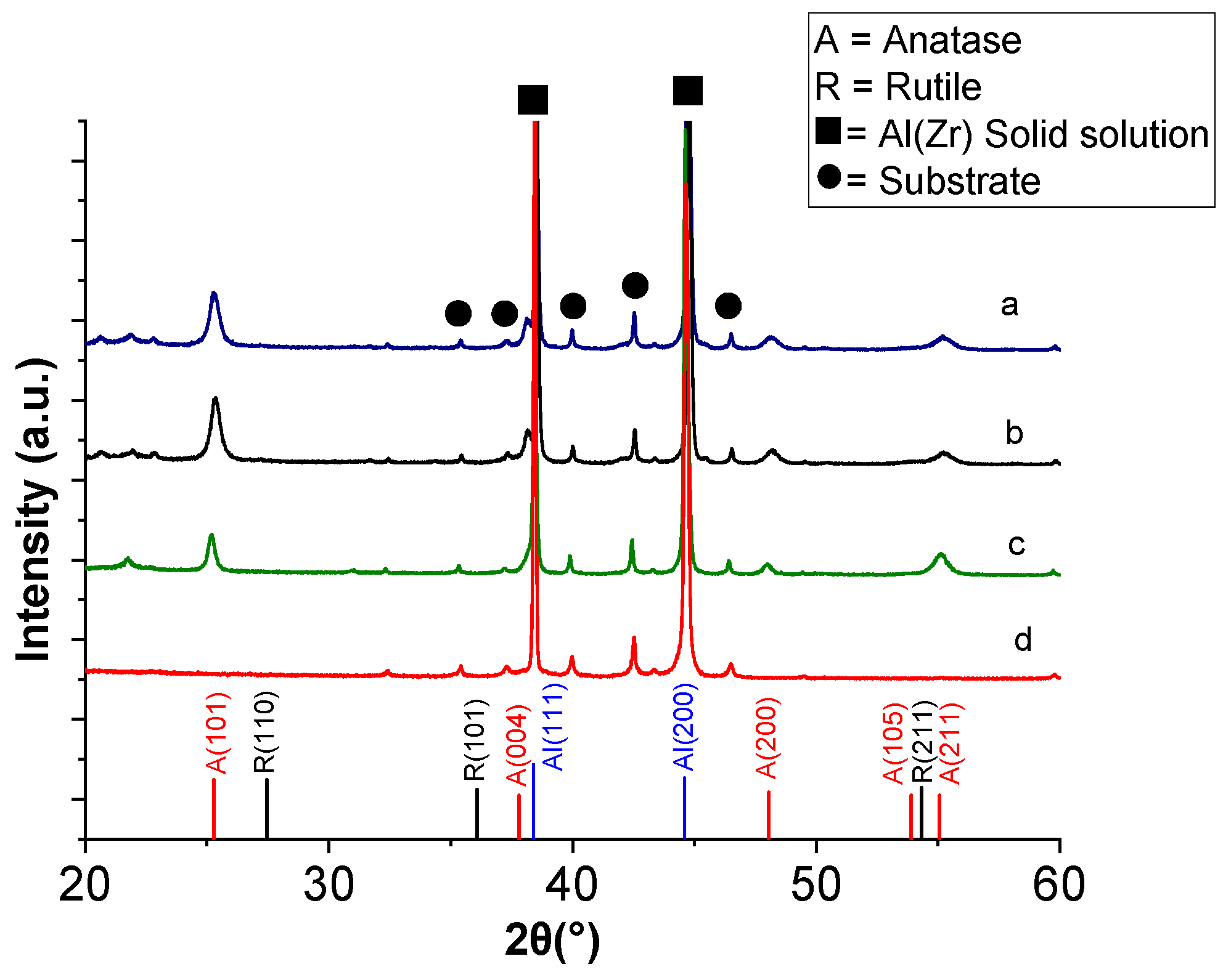
XRD characterisation was also performed after deposition of TiO2 at 500, 540 and 550 °C on the Al–Zr coated substrates for a deposition time of 40 min. The XRD patterns of these TiO2 coatings are shown in Figure 4. They reveal anatase phase in all samples, mainly detected by the (101) and (200) diffraction peaks at 25° and 48°, respectively, without the presence of a rutile phase, even for the highest deposition temperature of 550 °C. This is favorable because rutile has a lower charge-transfer rate and higher recombination rate of photogenerated electron–hole pairs than anatase [38].
Many works have been reported in the literature about the Raman signature of the different TiO2 phases [39]. Moreover, this technique is more sensitive to anatase, rutile, and amorphous phases of TiO2 films than XRD [40]. Besides, the technique is very local, allowing one to probe different microstructures at the sample surface.
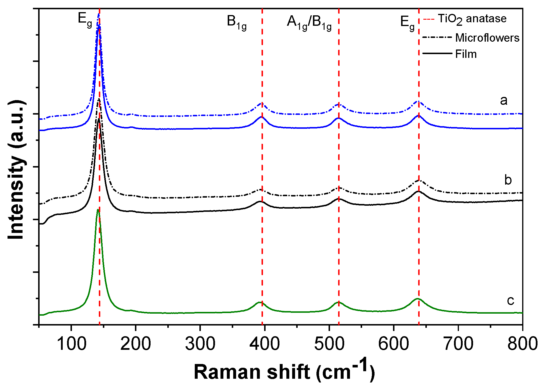
Figure 5 shows the Raman spectra of TiO2/Al–Zr multilayers for films deposited at different temperatures ranging between 500 and 550 °C. The Raman spectra of the film containing microflowers on the surface shows characteristic modes of the TiO2 anatase phase [41]: two Eg modes at 141 and 635 cm−1, one A1g mode at 513 cm−1 and one B1g mode at 397.5 cm−1. The sharp peak at 144 cm−1 clearly identifies the anatase phase of TiO2. Smaller peaks at 398 and 639 cm−1 can also be assigned to the anatase phase. No band corresponding to the rutile phase of TiO2 was observed. Moreover, the absence of a broadband background in the Raman spectra allows one to discard the growth of amorphous TiO2.
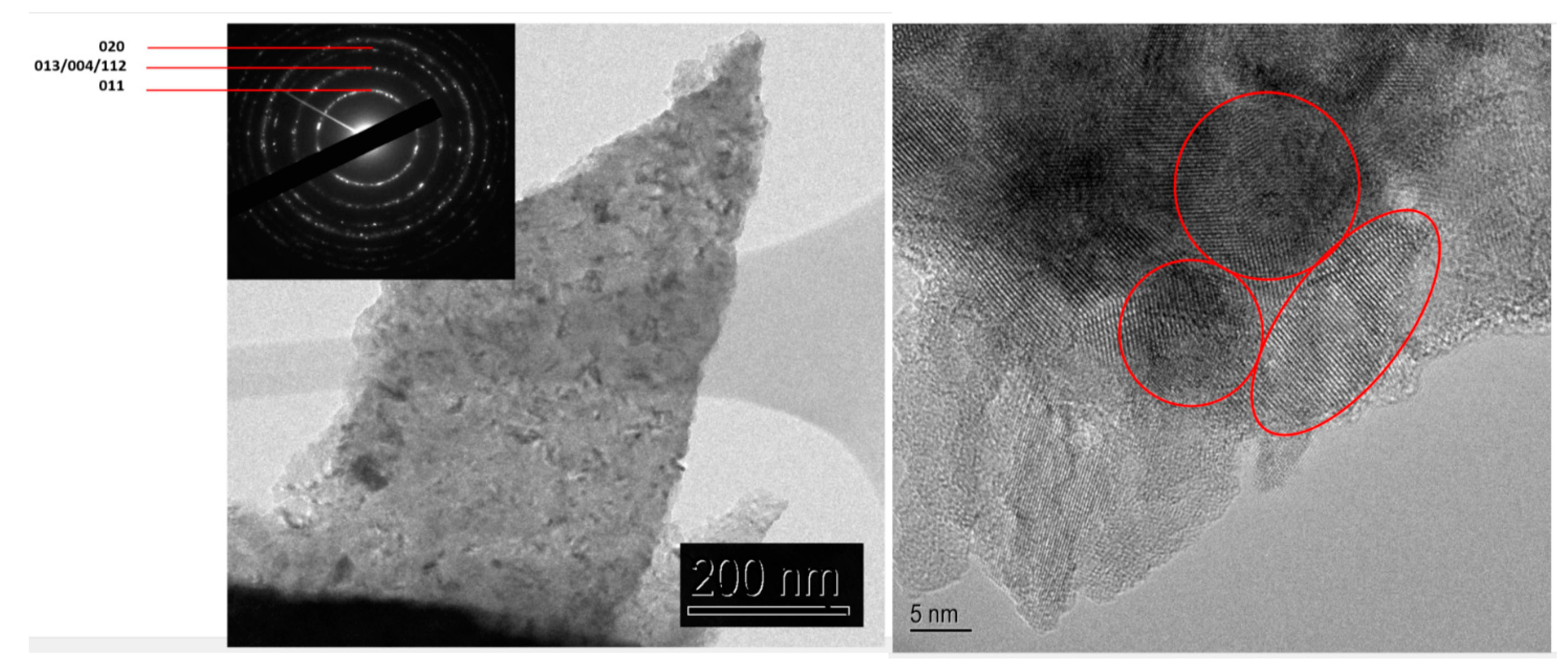
TEM observations show that the coatings are composed of anatase TiO2 nanograins as deduced from the diffraction pattern (Figure 6) with a grain size about 10–20 nm.

3.3. Photocatalytic Properties

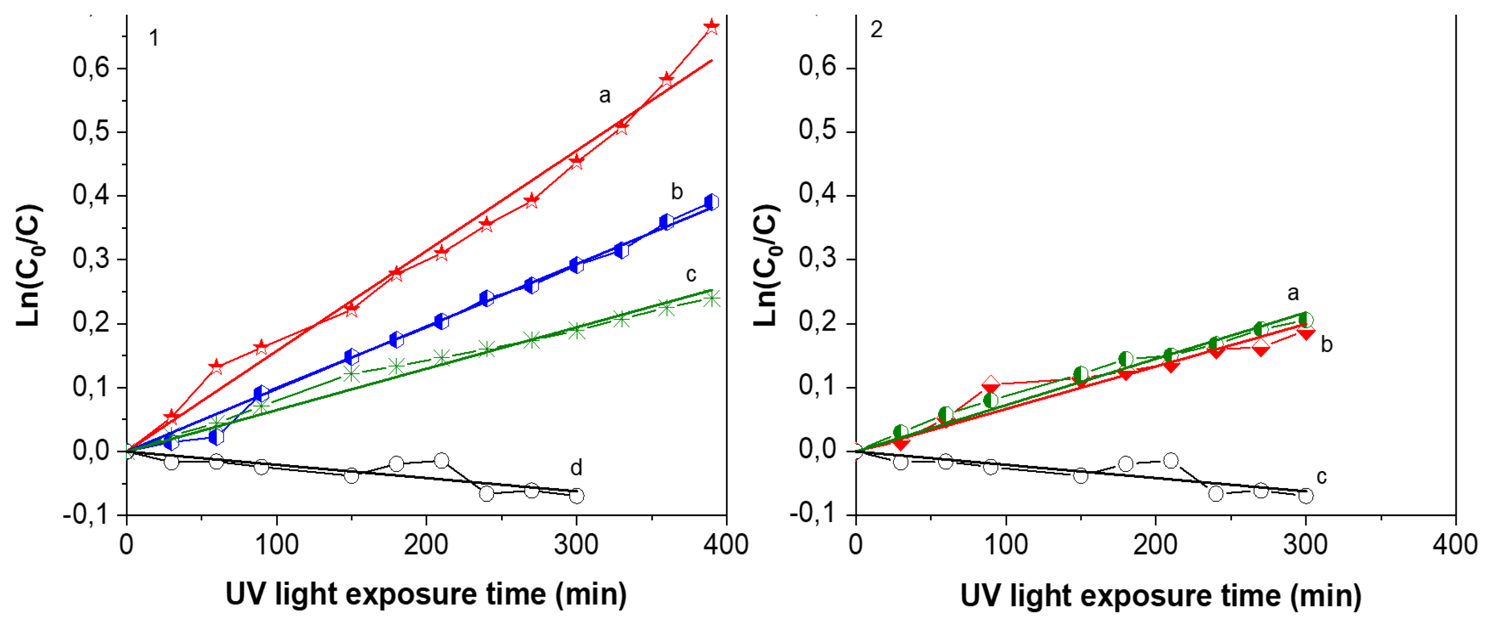
The evolution of the absorption band at 480 nm corresponding to Orange G allows one to quantify the concentration variation with UV exposure time. Figure 7 shows plots of Ln(C/C0) as a function of UV light irradiation time. Al–Zr coating was tested for verification and, as expected, this layer doesn’t present any photocatalytic activity as indicated by an almost constant slope. On the contrary, the concentration of orange G decreases when exposed to TiO2 films. Two kinds of TiO2 films were deposited to highlight the influence of microflowers in photocatalytic properties. Using the same deposition temperature, the precursor flowrate was slightly decreased to deposit TiO2 films without flowers. Theses layer present the same morphology and crystallized also in anatase phase (SEM and XRD are shown in the Supplementary Materials). The photocatalytic activity of these 2 series are represented in Figure 7. For films containing TiO2 microflowers, the deposition temperature has an influence on the degradation rate, with a maximum value in the case of the film deposited at 550 °C, which shows 50% of mineralization after 400 min of UV light exposure. For the film deposited at 540 °C, the value is 30% of mineralization for the same exposition time and only 20% for the film deposited at 500 °C. It is important to notice that microflowers structure were mainly present in samples deposited ant 540 and 550 °C, creating a higher roughness and a larger surface for chemical exchange or reaction. The k constant for Orange G degradation calculated from the slope with Formula (3) is resumed in Table 1. For films without microflowers deposited at 500 and 550 °C, as represented in Figure 7-2, the k constant obtained by a linear regression is one order of magnitude lower than films containing microflowers deposited at the same temperature.
Eufinger et al. demonstrated that low grain diameter (<50 nm) increases the active surface area [42]. Other papers show that TiO2 photoactivity is related to grain size [43]. In our case, films are formed of a double morphology that evolves in a different way. To determine the crystallite size evolution with temperature on the dense TiO2 film without flowers, we performed XRD diffraction on TiO2/Al–Zr films deposited on polished HSS substrate. In this case, the grain size obtained by Scherer’s method given in Formula (1) are 44 nm for film deposited at 500 °C and 53 nm for films deposited at 550 °C. However, if we calculate crystallite size from the samples containing flowers, the value are 18 nm and 20 nm for 500 and 550 °C, respectively. As the mean value includes the crystallites size from the film that should be equivalent to previous values in TiO2 films, we can infer that crystallites size contained in the microflowers are rather smaller to 18 nm, in agreement with TEM observations. The crystal values for TiO2/Al–Zr coatings deposited at 500 and 550 °C are resumed in Table 2.
The decomposition rate (DR) is calculated by multiplying the initial concentration of Orange G C0 = 5 × 10⁻⁵ M by the constant k. These values are also resumed in Table 2 for the TiO2/Al–Zr coatings deposited at 500 and 550 °C.
Maury et al. [44] reported a maximum DR of Orange G solution (10 ppm) of about 280 × 10−10 mol L−1 min−1 for TiO2 films deposited at 400 °C by AAMOCVD containing pure anatase phase.
In our work, the increase in decomposition rate from 332 × 10−10 mol L−1 min−1 for the TiO2/Al–Zr film deposited at 500 °C to 780 × 10−10 mol L−1 min−1 for the sample deposited at 550° is observed only in samples containing flowers. For samples without flowers de DR is similar or even lower than reported values.
The presence of microflowers with nanometric crystallite size contributes to a large specific surface, which can enhance the photocatalytic activity and improves the degradation rate of organic pollutants by multiplying the active sites for absorption in TiO2 [45,46]. By increasing the surface area, adsorption of the reactants upon the photocatalyst and absorption of the light will increase. This is the twofold interest of the microflower activity.

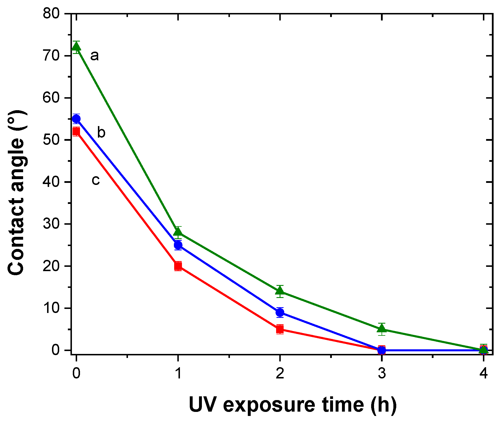
3.4. Hydrophilicity of TiO2/Al–Zr Bilayer Films

Hydrophilicity is usually present in materials with photocatalitic activity [46]. This property can be enhanced, and even restored, by UV exposure. The self-cleaning property is directly related to this material feature [46]. TiO2/Al–Zr thin films were irradiated with UV light during 4 h and the water contact angle was measured at different exposure times. A total of 10 measurements were made for each sample and results are presented in Figure 8. For all the samples, the contact angle decreases sharply with the time from values around 60° and reaching 0° after 4 h of UV exposure indicating a photoinduced superhydrophilicity. After six months in the absence of UV irradiation, the samples remained superhydrophilic presenting a contact angle of about 5°.
In the water contact angle measurements, high photoactivity means that the photogenerated holes attract hydroxyl groups from water and produce hydroxyl radicals (•OH). The higher the number of hydroxyl molecules on the surface, the higher is its hydrophilicity. This is presented as a small contact angle between the water droplet and the TiO2 surface.

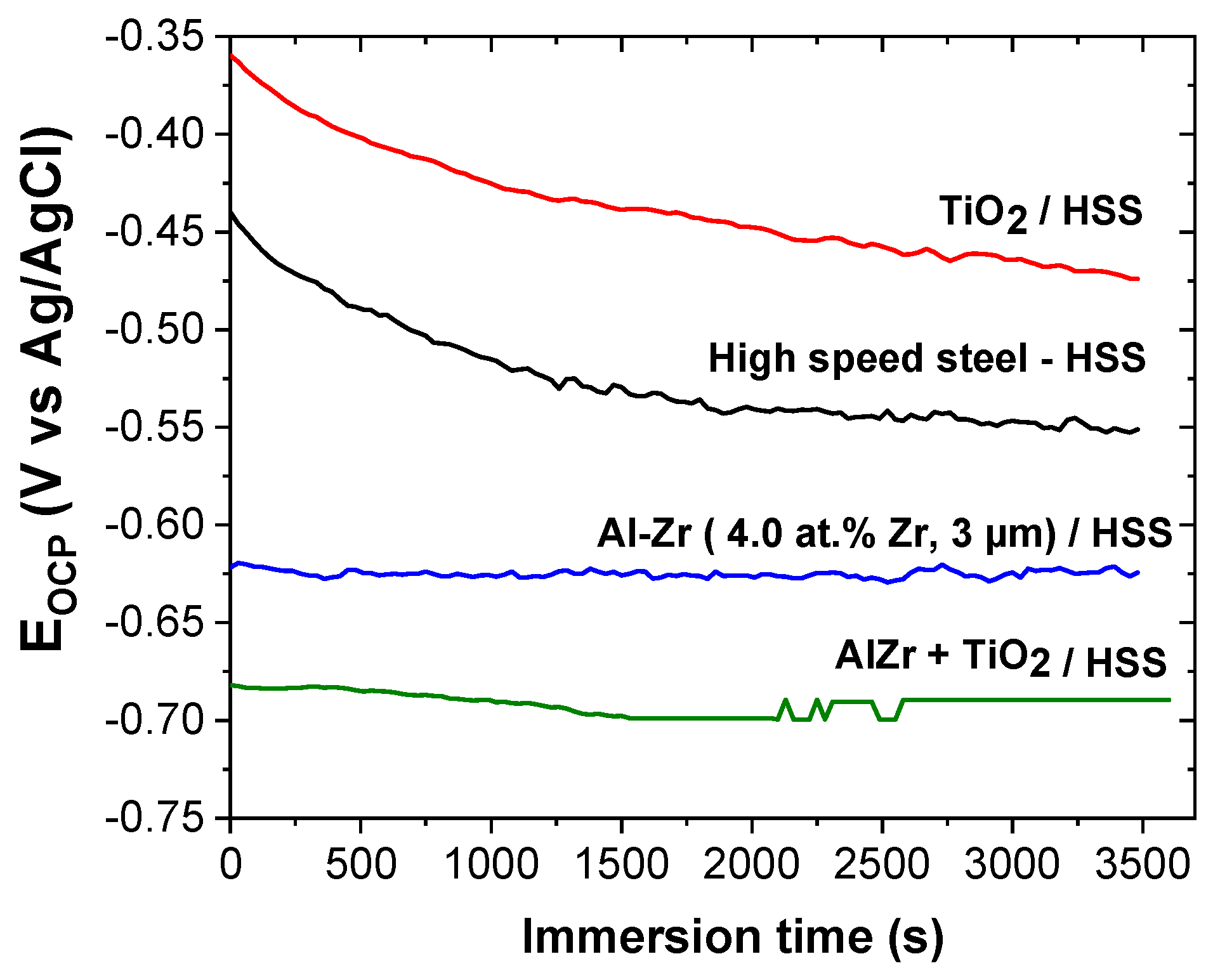
3.5. Electrochemical Behavior

Creus et al. presented the classification of aluminum based alloys in saline solution where the addition of Zr as a transition metal induces the ennoblement of the corrosion potential compared to pure aluminum without losing the sacrificial character [25]. In our work, Al–Zr films containing 4 at.% Zr were deposited on HSS substrate because this composition is the best compromise between mechanical properties, electrochemical behavior, and sacrificial character.
Figure 9 shows the evolution of the open circuit potential (OCP) versus time during 1 h of immersion in 5 wt.% NaCl for different coatings: Al–Zr, TiO2, and the bilayer TiO2/Al–Zr. The steel OCP is also reported as a reference. The steel OCP rapidly decreases and then stabilizes at around −0.55 V/Ag-AgCl. This evolution is typical of the progressive formation of iron-based corrosion products on the steel surface [47]. The TiO2 coated steel presents a quite similar OCP evolution during the immersion suggesting that this evolution is directly linked to the steel degradation through the open defects of the oxide film. However, the OCP values are nobler in the presence of the titanium oxide layer. Ramaprakash et al. [48] also observed a slight ennoblement of the steel corrosion potential when is covered with TiO2 in 3.5% NaCl solution. This ennoblement was attributed to the modification of the electronic charge transfer during the steel dissolution due to the presence of the oxide film.
The OCP of the Al–Zr coating is quite constant during the immersion at around −0.62 V/Ag-AgCl, which seems to be closed to the pitting potential as mentioned in [25] for similar Al-based coatings in saline solution. The OCP of the bilayer TiO2/Al–Zr coating is also quite constant during the immersion at around at −0.69 V/Ag-AgCl, which is slightly more negative compared with the Al–Zr coating. The shift of the OCP towards more negative values was also reported by Dias et al. on TiO2 thin films deposited by atomic layer deposition on Al–Mn alloys [49].
The OCP measurements prove that Al–Zr and TiO2/Al–Zr bilayer coatings keep the sacrificial character. It seems that the presence of the TiO2 coatings acts differently when is deposited onto steel or aluminum based materials, this could be due to the intrinsic properties of the titanium oxide film.
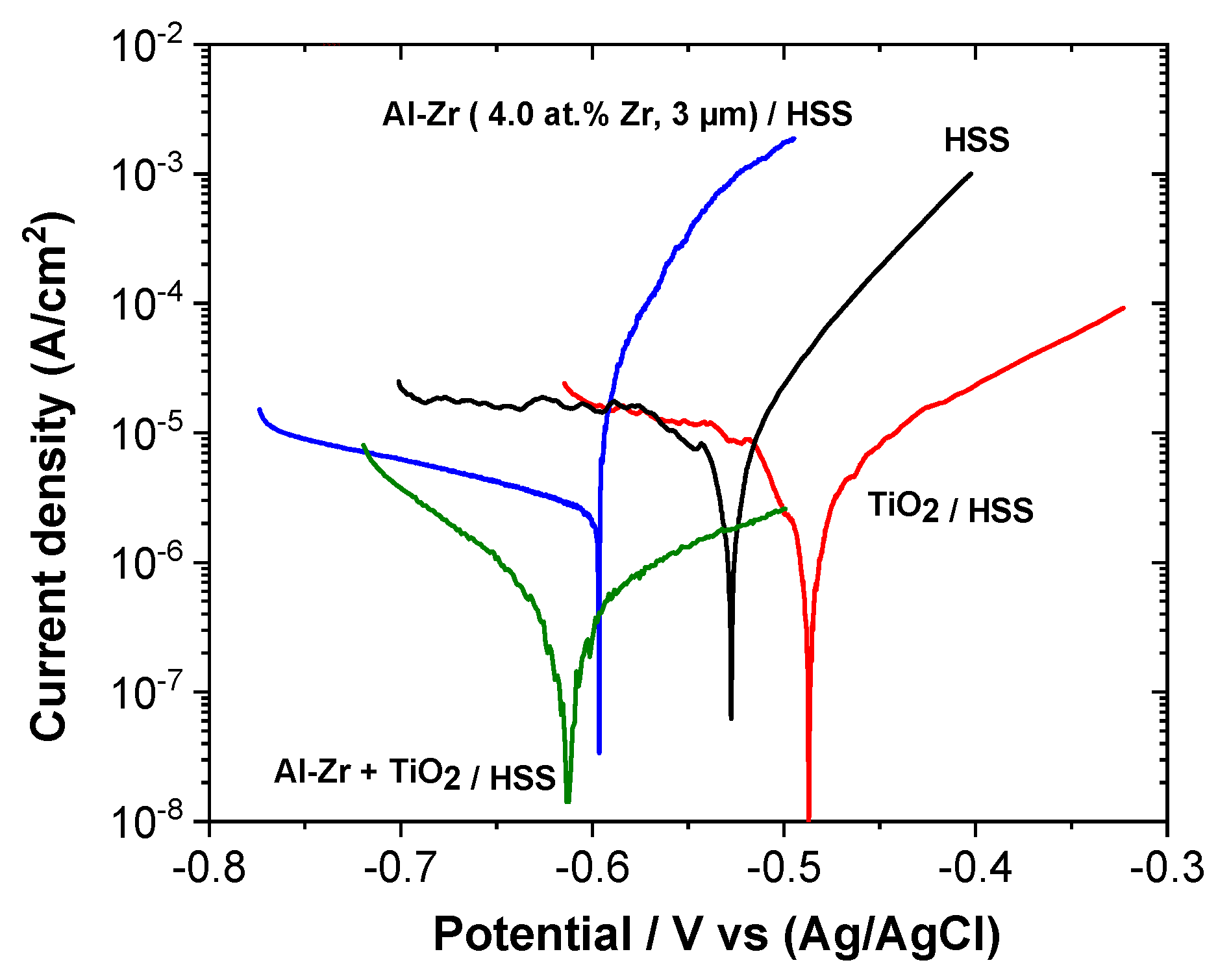
The polarization curves of the coated steels: Al–Zr, TiO2, and the bilayer TiO2/Al–Zr are presented in Figure 10 and compared with the bare steel. Corrosion potential (Ecorr) and corrosion current density (Icorr) were determined from the polarization curves by imposing a straight line along the linear portion of the anodic and cathodic curve and extrapolate it through Ecorr. Table 3 gathers the corrosion current density and corrosion potential values extracted from the potentiodynamic test for all the samples.
The corrosion potential of the bare steel after one hour of immersion in stirred saline solution is around −0.52 V vs. Ag/AgCl. A diffusional plateau is observed in the cathodic domain corresponding to the dioxygen reduction and a uniform corrosion is observed in the anodic domain. The TiO2 film induces a shift of the corrosion potential towards more positive values as observed by Ramaprakash et al. [48]. The cathodic branch is not affected by the presence of the titanium oxide film, whereas the steel dissolution mechanism is modified. The anodic slope is decreased suggesting that the oxide film affects the charge transfer reactions during the steel dissolution.
Al–Zr coating presents a corrosion potential at around −0.59 V vs. Ag/AgCl which is slightly more negative compared to the HSS substrate suggesting that the Al-based coatings present a sacrificial behavior compared to steel. The anodic polarization curve presents a sudden rise in current close to the corrosion potential corresponding to the initiation of pitting corrosion as presented by Creus et al. [25]. We can notice that the initiation of the pitting corrosion occurs at a potential value that is close to the corrosion potential.
The polarization curve for the bilayer coated sample (TiO2/Al–Zr) is quite different from the other configurations. The influence of the TiO2 film on the corrosion behavior is different when deposited on HSS steel or on Al–Zr coating, probably due to the fact that steel suffers from a uniform corrosion whereas pitting corrosion is the main degradation observed on Al–Zr coating. The TiO2 oxide film affects the cathodic domain with an increase of the cathodic reaction slope associated with the dioxygen reduction, suggesting that the charge transfer step in the dioxygen reduction reaction is slow down. The TiO2 film permits to reduce the contribution of the cathodic reactions leading to the decrease of the corrosion current density, down to 4.1 × 10⁻⁷ A/cm2. As observed for the Al–Zr coating, the pitting corrosion occurs at potential values very close to the corrosion potential, but in the bilayer coating, we can suppose that the pit initiation is mainly localized near the oxide film defects. An important decrease of the anodic reaction kinetic probably due to the increase of the surface impedance associated to the TiO2 layer is observed. So the pit propagation seems to be reduced in the presence of the oxide film.
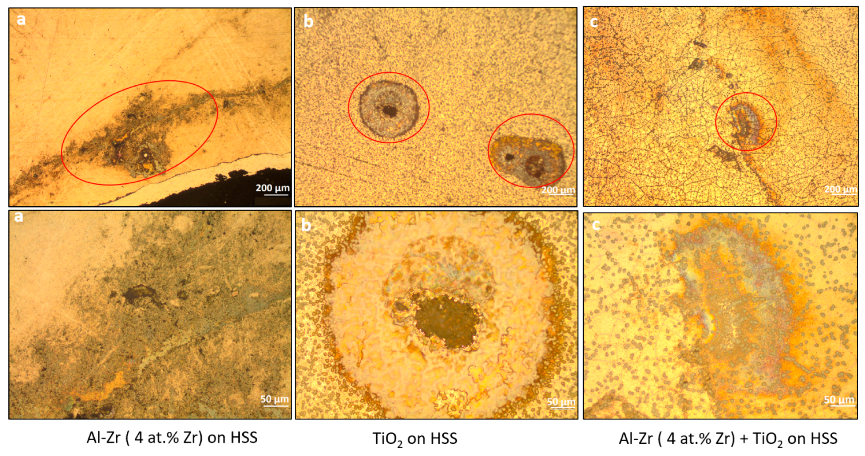
The optical observations of the corroded surface of the coated samples after the potentiodynamic polarization are presented in Figure 11. It shows that the mean pit diameter decreases when TiO2 is added as a second layer. It suggests that the TiO2 coating impede the growth of pits. We can infer that the TiO2 layer is able to increase the pitting resistance due to the fact that the cathodic reaction kinetic is lower.

4. Conclusions

The potential functionality of a TiO2/Al–Zr bilayer coating combining anticorrosion and photocatalysis properties has been tested using high-speed steel (HSS) as substrates. The Al–Zr thin films containing a supersaturated solid solution with 4 at.% Zr were deposited on HSS substrates by DC magnetron sputtering. Then, TiO2 coatings were deposited by aerosol-assisted CVD in optimized conditions to grow a microstructure characterized by the presence of TiO2 microflowers physically attached to the TiO2 thin film. Optimal growth conditions were obtained by the combination of deposition temperature, precursor concentration, and precursor feeding rate [18]. XRD and Raman spectroscopy confirm that TiO2 microflowers and thin film consist of TiO2 in anatase phase. The presence of TiO2 microflowers having a diameter and height of about 7 µm and a crystallite size of 20 nm plays a crucial role in photocatalysis of Orange G compound. This behavior is enhanced on TiO2 samples deposited at 550 °C, showing a higher decomposition rate of Orange G (780 × 10−10 mol L−1) under UV light irradiation when compared to others films deposited at lower deposition temperatures (500 and 540 °C).
Finally, Al–Zr/TiO2 bilayer coatings were found to be an interesting alternative to preserve sacrificial character for the protection of steel structures in saline environments, showing a corrosion potential of −0.61 V vs. Ag/AgCl. TiO2/Al–Zr bilayer coatings deposited on steel substrates offer good protection through the preferential oxidation of the bilayer presenting a lower corrosion current density of 4.01 × 10⁻⁷ A/cm2. TiO2 as a second layer reduces the electrochemical activity of the films through the formation of a dense passive film and also increases the pitting resistance since the cathodic reaction kinetic is lower.
This study confirms the fundamental role of roughness and superhydrophilicity on the photocatalysis process and encourage the application of TiO2 nano-coatings for the fabrication of components to avoid algal adhesion on underwater structures. Biofouling field tests should be carried out in order to evaluate the performance of coatings in real conditions.

Supplementary Materials

The following are available online at https://www.mdpi.com/2079-6412/9/9/564/s1, Figure S1: XRD Patterns for TiO2/Al-Zr thin films without microflowers deposited at (a) 500 °C, (b) 550 °C and (c) Al-Zr, Figure S2: XRD patterns for TiO2/Al-Zr thin films with microflowers deposited at (a) 550 °C, (b) 540 °C and (c) 500 °C on (d) Al-Zr, Figure S3: SEM images of TiO2/Al-Zr film without microflowers deposited at 550 °C, Figure S4: Decomposition of Orange G by TiO2/Al-Zr thin films with microflowers (left) deposited at (a) 550°, (b) 540 °C, (c) 500 °C and (d) Al-Zr as underlayer Zr under UV light (371 nm) irradiation time. TiO2/Al-Zr thin films without microflowers (right) deposited at (a) 500 °C and (b) 550 °C and (c) Al-Zr underlayer under UV light (371 nm) irradiation time.

Author Contributions

Conceptualization, C.V.d.O., C.J., A.A., F.S. (Frédéric Sanchette); Methodology, C.V.d.O, C.J., A.A.; Validation, C.V.d.O. and F.S. (Frédéric Sanchette); Formal Analysis, C.V.d.O., J.C., A.A. and C.J.; Investigation, C.V.d.O., C.J., J.C., M.L.S. and Z.D.; Resources, C.J., M.L.S., J.C. and Z.D.; Data Curation, C.V.d.O. and C.J.; Writing-Original Draft Preparation, C.V.d.O.; Writing-Review & Editing, C.V.d.O., A.A., C.J., F.S. (Frédéric Sanchette) and J.C.; Visualization, C.V.d.O.; Supervision, F.S. (Frédéric Sanchette), A.A. and C.J.; Project Administration, F.S. (Frédéric Sanchette) and F.S. (Frédéric Schuster); Funding Acquisition, F.S. (Frédéric Sanchette) and F.S. (Frédéric Schuster).

Funding

This research was co-funded by the Université de Technologie de Troyes and CEA Saclay.

Acknowledgments

This work was performed within the framework of the Centre of Excellence of Multifunctional Architectured Materials “CEMAM” no. ANR-10-LABX-44-01. We thank Jean-Luc Deschanvres and David Riasseto for the fruitful discussions.

Conflicts of Interest

The authors declare no conflict of interest.

References

  1. Sudha, P.N.; Gomathi, T.; Venkatesan, J.; Kim, S.-K. Marine Biomaterials as Antifouling Agent; Springer Science and Business Media LLC: Berlin, Germany, 2015. [Google Scholar]
  2. Dobretsov, S.; Teplitski, M.; Paul, V. Mini-review: Quorum sensing in the marine environment and its relationship to biofouling. Biofouling 2009, 25, 413–427. [Google Scholar] [CrossRef] [PubMed]
  3. Magin, C.M.; Cooper, S.P.; Brennan, A.B. Non-toxic antifouling strategies. Mater. Today 2010, 13, 36–44. [Google Scholar] [CrossRef]
  4. Sathe, P.; Laxman, K.; Myint, M.T.Z.; Dobretsov, S.; Richter, J.; Dutta, J. Bioinspired nanocoatings for biofouling prevention by photocatalytic redox reactions. Sci. Rep. 2017, 7, 3624. [Google Scholar] [CrossRef] [PubMed]
  5. Sathe, P.; Richter, J.; Myint, M.T.Z.; Dobretsov, S.; Dutta, J. Self-decontaminating photocatalytic zinc oxide nanorod coatings for prevention of marine microfouling: A mesocosm study. Biofouling 2016, 32, 383–395. [Google Scholar] [CrossRef] [PubMed]
  6. Baruah, S.; Jaisai, M.; Dutta, J. Development of a visible light active photocatalytic portable water purification unit using ZnO nanorods. Catal. Sci. Technol. 2012, 2, 918–921. [Google Scholar] [CrossRef]
  7. Sathe, P.; Myint, M.T.Z.; Dobretsov, S.; Dutta, J. Removal and regrowth inhibition of microalgae using visible light photocatalysis with ZnO nanorods: A green technology. Sep. Purif. Technol. 2016, 162, 61–67. [Google Scholar] [CrossRef]
  8. Gerchakov, S.M.; Sallman, B. Biofouling and Effects of Organic Compounds and Microorganisms on Corrosion Processes; Miami University: Oxford, OH, USA, 1977. [Google Scholar]
  9. Mollica, A. Biofilm and corrosion on active-passive alloys in seawater. Int. Biodeterior. Biodegradation 1992, 29, 213–229. [Google Scholar] [CrossRef]
  10. Zobell, C.E.; Allen, E.C. The Significance of Marine Bacteria in the Fouling of Submerged Surfaces. J. Bacteriol. 1935, 29, 239–251. [Google Scholar] [PubMed]
  11. Callow, M.E.; Fletcher, R.L. The influence of low surface energy materials on bioadhesion—A review. Int. Biodeterior. Biodegradation 1994, 34, 333–348. [Google Scholar] [CrossRef]
  12. M-503 Cathodic Protection, 4th ed.; Standards Norway: Oslo, Norway, 2016; NORSOK M-503:2016.
  13. Mills, A.; Elliott, N.; Parkin, I.P.; O’Neill, S.A.; Clark, R.J. Novel TiO2 CVD films for semiconductor photocatalysis. J. Photochem. Photobiol. A Chem. 2002, 151, 171–179. [Google Scholar] [CrossRef]
  14. Fujishima, A.; Honda, K. Electrochemical photolysis of water at a semiconductor electrode. Nature 1972, 238, 37–38. [Google Scholar] [CrossRef] [PubMed]
  15. Herrmann, J.-M.; Duchamp, C.; Karkmaz, M.; Hoai, B.T.; Lachheb, H.; Puzenat, E.; Guillard, C. Environmental green chemistry as defined by photocatalysis. J. Hazard. Mater. 2007, 146, 624–629. [Google Scholar] [CrossRef] [PubMed]
  16. Tian, G.; Chen, Y.; Zhou, W.; Pan, K.; Tian, C.; Huang, X.-R.; Fu, H. 3D hierarchical flower-like TiO2 nanostructure: Morphology control and its photocatalytic property. CrystEngComm 2011, 13, 2994. [Google Scholar] [CrossRef]
  17. Zhu, T.; Li, J.; Wu, Q. Construction of TiO2 hierarchical nanostructures from nanocrystals and their photocatalytic properties. ACS Appl. Mater. Interfaces 2011, 3, 3448–3453. [Google Scholar] [CrossRef] [PubMed]
  18. Biswas, S.; Jiménez, C.; Khan, A.; Forissier, S.; Kar, A.K.; Muñoz-Rojas, D.; Deschanvres, J.-L. Structural study of TiO2 hierarchical microflowers grown by aerosol-assisted MOCVD. CrystEngComm 2017, 19, 1535–1544. [Google Scholar] [CrossRef]
  19. Sanchette, F.; Czerwiec, T.; Billard, A.; Frantz, C. Sputtering of Al-Cr and Al-Ti composite targets in pure Ar and in reactive Ar-N2 plasmas. Surf. Coat. Technol. 1997, 96, 184–190. [Google Scholar] [CrossRef]
  20. Sanchette, F.; Loi, T.H.; Billard, A.; Frantz, C. Structure—Properties relationship of metastable Al-Cr and Al-Ti alloys deposited by r.f. magnetron sputtering: role of nitrogen. Surf. Coat. Technol. 1995, 74, 903–909. [Google Scholar] [CrossRef]
  21. Sanchette, F.; Billard, A.; Frantz, C. Amorphous aluminium alloy coatings. Surf. Coat. Technol. 1998, 98, 1162–1168. [Google Scholar] [CrossRef]
  22. Sanchette, F.; Billard, A. Main features of magnetron sputtered aluminium–transition metal alloy coatings. Surf. Coat. Technol. 2001, 142, 218–224. [Google Scholar] [CrossRef]
  23. Perez, A.; Sanchette, F.; Billard, A.; Rébéré, C.; Berziou, C.; Touzain, S.; Creus, J. Comparison of the intrinsic properties of EBPVD Al–Ti and Al–Mg coatings. Mater. Chem. Phys. 2012, 132, 154–161. [Google Scholar] [CrossRef]
  24. Sanchette, F.; Ducros, C.; Billard, A.; Rébéré, C.; Berziou, C.; Reffass, M.; Creus, J. Nanostructured aluminium based coatings deposited by electron-beam evaporative PVD. Thin Solid Films 2009, 518, 1575–1580. [Google Scholar] [CrossRef]
  25. Creus, J.; Berziou, C.; Cohendoz, S.; Perez, A.; Rébéré, C.; Reffass, M.; Touzain, S.; Allely, C.; Gachon, Y.; Héau, C.; et al. Reactivity classification in saline solution of magnetron sputtered or EBPVD pure metallic, nitride and Al-based alloy coatings. Corros. Sci. 2012, 57, 162–173. [Google Scholar] [CrossRef]
  26. Reffass, M.; Berziou, C.; Rébéré, C.; Billard, A.; Creus, J. Corrosion behaviour of magnetron-sputtered Al1−x–Mnx coatings in neutral saline solution. Corros. Sci. 2010, 52, 3615–3623. [Google Scholar] [CrossRef]
  27. Berziou, C.; Remy, K.; Billard, A.; Creus, J. Corrosion behaviour of dc magnetron sputtered Fe1−xMgx alloy films in 3wt% NaCl solution. Corros. Sci. 2007, 49, 4276–4295. [Google Scholar] [CrossRef]
  28. Brodova, I.G.; Bashlykov, D.V.; Manukhin, A.B.; Stolyarov, V.V.; Soshnikova, E.P. Formation of nanostructure in rapidly solidified Al-Zr alloy by severe plastic deformation. Scr. Mater. 2001, 44, 1761–1764. [Google Scholar]
  29. Yoshioka, H.; Habazaki, H.; Kawashima, A.; Asami, K.; Hashimoto, K. The corrosion behavior of sputter-deposited Al-Zr alloys in 1 M HCl solution. Corros. Sci. 1992, 33, 425–436. [Google Scholar] [CrossRef]
  30. Chaudhury, Z.A.; Suryanarayana, C. A TEM study of decomposition behavior of a melt-quenched Al-Zr alloy. Met. 1984, 17, 231–252. [Google Scholar] [CrossRef]
  31. Srinivasarao, B.; Suryanarayana, C.; Oh-Ishi, K.; Hono, K. Microstructure and mechanical properties of Al–Zr nanocomposite materials. Mater. Sci. Eng. A 2009, 518, 100–107. [Google Scholar] [CrossRef]
  32. Ho, J.-K.; Lin, K.-L. The metastable Al-Zr alloy thin films prepared by alternate sputtering deposition. J. Appl. Phys. 1994, 75, 2434–2440. [Google Scholar] [CrossRef]
  33. Rittner, M.; Weertman, J.; Eastman, J. Structure-property correlations in nanocrystalline Al-Zr alloy composites. Acta Mater. 1996, 44, 1271–1286. [Google Scholar] [CrossRef]
  34. Reffass, M.; Billard, A.; Conforto, E.; Sanchette, F.; Creus, J. Intrinsic structural, mechanical and corrosion properties of sputtered Al-Zr thin films. In Proceedings of the Presentation B1-3-7 in 42nd International Conference on Metallurgical Coatings and thin Films (ICMCTF), San Diego, CA, USA, 20–24 April 2015. [Google Scholar]
  35. Liu, H.; Nguyen, V.H.; Roussel, H.; Gélard, I.; Rapenne, L.; Deschanvres, J.-L.; Jiménez, C.; Muñoz-Rojas, D. Cu2O thin films: The role of humidity in tuning the texture and electrical properties of Cu2O thin films deposited via aerosol-assisted CVD (Adv. Mater. Interfaces 3/2019. Adv. Mater. Interfaces 2019, 6, 1970020. [Google Scholar] [CrossRef]
  36. B46.1-1995 Surface Texture—Surface Roughness, Waviness, and Lay; The American Society of Mechanical Engineers: New York, NY, USA, 1995.
  37. Zhang, Z.; Shao, C.; Li, X.; Wang, C.; Zhang, M.; Liu, Y. Electrospun nanofibers of p-type NiO/n-type ZnO heterojunctions with enhanced photocatalytic activity. ACS Appl. Mater. Interfaces 2010, 2, 2915–2923. [Google Scholar] [CrossRef] [PubMed]
  38. Jung, Y.-S.; Kim, K.-H.; Jang, T.-Y.; Tak, Y.; Baeck, S.-H. Enhancement of photocatalytic properties of Cr2O3–TiO2 mixed oxides prepared by sol–gel method. Curr. Appl. Phys. 2011, 11, 358–361. [Google Scholar] [CrossRef]
  39. Boukrouh, S.; Bensaha, R.; Bourgeois, S.; Finot, E.; De Lucas, M.M. Reactive direct current magnetron sputtered TiO2 thin films with amorphous to crystalline structures. Thin Solid Films 2008, 516, 6353–6358. [Google Scholar] [CrossRef]
  40. Brevet, A.; Fabreguette, F.; Imhoff, L.; De Lucas, M.M.; Heintz, O.; Saviot, L.; Sacilotti, M.; Bourgeois, S. Thermal effects on the growth by metal organic chemical vapour deposition of TiO2 thin films on (100) GaAs substrates. Surf. Coat. Technol. 2002, 151, 36–41. [Google Scholar] [CrossRef]
  41. Busca, G.; Ramis, G.; Escribano, V.S.; Piaggio, P. FT Raman and FTIR studies of titanias and metatitanate powders. J. Chem. Soc. Faraday Trans. 1994, 90, 3181–3190. [Google Scholar] [CrossRef]
  42. Eufinger, K.; Poelman, D.; Poelman, H.; De Gryse, R.; Marin, G.B. applications. In Thin Solid Films: Process and Applications; Nam, S.C., Ed.; Transworld Research Network: Kerala, India, 2009; pp. 189–227. [Google Scholar]
  43. Zheng, X.; Kuang, Q.; Yan, K.; Qiu, Y.; Qiu, J.; Yang, S. Mesoporous TiO2 single crystals: Facile shape-, size-, and phase-controlled growth and efficient photocatalytic performance. ACS Appl. Mater. Interfaces 2013, 5, 11249–11257. [Google Scholar] [CrossRef] [PubMed]
  44. Duminica, F.-D.; Maury, F.; Hausbrand, R. Growth of TiO2 thin films by AP-MOCVD on stainless steel substrates for photocatalytic applications. Surf. Coat. Technol. 2007, 201, 9304–9308. [Google Scholar] [CrossRef]
  45. Kim, D.S.; Han, S.J.; Kwak, S.-Y. Synthesis and photocatalytic activity of mesoporous TiO2 with the surface area, crystallite size, and pore size. J. Colloid Interface Sci. 2007, 316, 85–91. [Google Scholar] [CrossRef] [PubMed]
  46. Anandan, S.; Narasinga Rao, T.; Sathish, M.; Rangappa, D.; Honma, I.; Miyauchi, M. Superhydrophilic graphene-loaded TiO2 thin film for self-cleaning applications. ACS Appl. Mater. Interfaces 2013, 5, 207–212. [Google Scholar] [CrossRef]
  47. Creus, J.; Idrissi, H.; Mazille, H. Galvanic corrosion behaviour of mild steel, Al, and Ti in 3%NaCl solution: Application to PVD coatings on steel substrate. Surf. Eng. 1997, 13, 415–419. [Google Scholar] [CrossRef]
  48. Ramaprakash, M.; Sreedhar, G.; Mohan, S.; Panda, S.K. Corrosion protection studies of CeO2–TiO2 nanocomposite coatings on mild steel. Trans. IMF 2016, 94, 254–258. [Google Scholar] [CrossRef]
  49. Dias, V.; Maciel, H.; Fraga, M.; Lobo, A.O.; Pessoa, R.; Marciano, F.R. Atomic layer deposited TiO2 and Al2O3 thin films as coatings for aluminum food packaging application. Materials 2019, 12, 682. [Google Scholar] [CrossRef] [PubMed]
Figure 1. SEM images of samples: (ac) Al–Zr (4 at.% Zr) coating, and TiO2 films deposited at (df) 500 °C, (gi) 540 °C, and (jl) 550 °C.
Coatings 09 00564 g001
Figure 2. Surface roughness patterns measured 25 mm along the surface.
Coatings 09 00564 g002
Figure 3. XRD patterns for the (a) HSS substrate, (b) as-deposited Al–Zr film on high-speed steel substrate, and (c) Al–Zr film annealed in the air at 500 °C.
Coatings 09 00564 g003
Figure 4. XRD patterns for TiO2 films deposited at (a) 550 °C, (b) 540 °C, and (c) 500 °C on (d) Al–Zr.
Coatings 09 00564 g004
Figure 5. Raman spectra for TiO2 films deposited by aerosol CVD at (a) 550 °C, (b) 540 °C, and (c) 500 °C.
Coatings 09 00564 g005
Figure 6. Bright field image from TiO2/Al–Zr film and the corresponding selected area electron diffraction pattern indicate the formation of the nanocrystalline anatase TiO2 phase.
Coatings 09 00564 g006
Figure 7. Evolution of the orange G degradation with UV light (371 nm) versus irradiation time for the TiO2/Al–Zr thin films deposited at (1a) 550°, (1b) 540 °C, (1c) 500 °C, with microflowers (left) and TiO2/Al–Zr thin films deposited at (2a) 500°, (2b) 550 °C without microflowers (right). The evolution of Al–Zr films are also presented on (1d) and (2c) for comparison.
Coatings 09 00564 g007
Figure 8. Variation of water contact angles under UV illumination with time for TiO2/AlZr bilayer samples deposited at (a) 500 °C, (b) 540 °C, and (c) 550 °C.
Coatings 09 00564 g008
Figure 9. Evolution of OCP potential of steel coated with Al–Zr (4 at.% Zr) film and TiO2/Al–Zr bilayer films vs. immersion time in 5 wt.% NaCl.
Coatings 09 00564 g009
Figure 10. Polarisation curves of Al–Zr (4 at.% Zr), TiO2, and TiO2/Al–Zr bilayer films deposited on HSS after 1 h of immersion in 5 wt.% NaCl.
Coatings 09 00564 g010
Figure 11. Optical micrographs of pits formed on (a) Al–Zr (4 at.% Zr), (b) TiO2, and (c) TiO2/Al–Zr bilayer films deposited on HSS after 1h of immersion in 5 wt.% NaCl.
Coatings 09 00564 g011
Table 1. Constant k (kinetic constant of the system) for TiO2/Al–Zr coatings deposited at different temperatures.
Samples with MicroflowersConstant k (min−1)
Al–Zr + TiO2 Tdep = 500 °C0.00063
Al–Zr + TiO2 Tdep = 540 °C0.00102
Al–Zr + TiO2 Tdep = 550 °C0.00156
Samples without MicroflowersConstant k (min−1)
Al–Zr + TiO2 Tdep = 500 °C0.00066
Al–Zr + TiO2 Tdep = 550 °C0.00059
Table 2. The effect of presence of microflowers on the decomposition rate and the crystal size for the TiO2/Al–Zr coatings deposited at 500 °C and 550 °C.
Samples with MicroflowersDR (10−10 mol L−1 min−1)Crystal Size (nm)
Al–Zr + TiO2 Tdep = 500 °C51018
Al–Zr + TiO2 Tdep = 550 °C78020
Samples without MicroflowersDR (10−10 mol L−1 min−1)Crystal Size (nm)
Al–Zr + TiO2 Tdep = 500 °C33244
Al–Zr + TiO2 Tdep = 550 °C29753
Table 3. Icorr and Ecorr values for Al–Zr, TiO2 films, Al–Zr/TiO2 films, and HSS substrate.
SamplesIcorr (A/cm2)Ecorr (V/(Ag/AgCl))
HSS substrate18 + −2−0.52 + −0.05
TiO29 + −1−0.48 + −0.05
Al–Zr (4 at.% Zr)2.5 + −0.3−0.59 + −0.06
Al–Zr + TiO20.41 + −0.05−0.61 + −0.06

