Article

Crack-Resistance Behavior of an Encapsulated, Healing Agent Embedded Buffer Layer on Self-Healing Thermal Barrier Coatings

1
Department of Energy Engineering, Hanyang University, Seoul 133-791, Korea
2
School of Materials Science and Engineering, Changwon National University, Changwon, Gyeongnam 641-773, Korea
3
High Temperature Materials Research Group, Korea Institute of Materials Science, 797 Changwondaero, Changwon, Gyeongnam 641-831, Korea
4
Department of Mechanical and Energy Engineering, Indiana University–Purdue University Indianapolis, Indianapolis, IN 46202-5132, USA
*
Authors to whom correspondence should be addressed.
Coatings 2019, 9(6), 358; https://doi.org/10.3390/coatings9060358
Submission received: 3 May 2019 / Revised: 27 May 2019 / Accepted: 29 May 2019 / Published: 31 May 2019
(This article belongs to the Special Issue Science and Technology of Thermal Barrier Coatings)

Abstract

:
In this work, a novel thermal barrier coating (TBC) system is proposed that embeds silicon particles in coating as a crack-healing agent. The healing agent is encapsulated to avoid unintended reactions and premature oxidation. Thermal durability of the developed TBCs is evaluated through cyclic thermal fatigue and jet engine thermal shock tests. Moreover, artificial cracks are introduced into the buffer layer’s cross section using a microhardness indentation method. Then, the indented TBC specimens are subject to heat treatment to investigate their crack-resisting behavior in detail. The TBC specimens with the embedded healing agents exhibit a relatively better thermal fatigue resistance than the conventional TBCs. The encapsulated healing agent protects rapid large crack openings under thermal shock conditions. Different crack-resisting behaviors and mechanisms are proposed depending on the embedding healing agents.

1. Introduction

Thermal barrier coatings (TBCs) are used to enhance the energy efficiency and durability of hot components of gas turbines or aerospace engines [1,2,3,4,5]. Typical TBCs are fabricated on the substrate of an Ni-based superalloy. MCrAlY (M = Ni and/or Co) is usually deposited to form a bond coat layer, which can enhance the bonding strength between the metallic substrate and ceramic top coat and protect the substrate from oxidation and corrosion [5,6,7]. Then, yttria-stabilized zirconia (YSZ) is typically used as a top coat material because of its excellent thermomechanical properties, such as low thermal conductivity (≈ 2.3 W/(m·K) at 1000 °C), and high coefficient of thermal expansion (CTE), which is similar to the bond coat (top: ≈11·10−6/°C, bond: ≈14 × 10−6/°C) [8,9,10,11,12,13].
During the actual operating service, TBCs are exposed to severe conditions with the following complex phenomena [14,15]: thermomechanical stresses, erosion, corrosion by foreign objects, diffusion, oxidation, phase transformation, and sintering. In particular, abrupt thermomechanical stress during starting up and shutting down is one of the key factors for damage accumulation, which can lead to formation and propagation of cracks and ultimately result in the failure of the TBCs [16,17,18]. Because of these harsh environmental factors, heavy costs are incurred for repairing, refurbishing, or replacing the hot components.
Several attempts have been made to enhance the thermal durability of TBCs. From the coating design perspective, Taylor [19] developed dense vertically cracked (DVC) TBCs, which greatly improved the strain tolerance. Graded and multilayer coatings were also proposed to reduce residual stress and enhance the cohesion and structural stability [20,21]. On the other hand, evaporation technologies such as electron beam physical vapor deposition methods emerged in the 1980s [22], forming columnar and intercolumnar microstructures of the top coat, which can noticeably enhance strain tolerance [23]. Padture et al. [24] demonstrated the feasibility of the solution precursor plasma spray (SPPS) as a new processing method because SPPS coatings have unique microstructures that contain features of both conventional plasma-sprayed TBCs and DVC TBCs. Similarly, suspension plasma spraying was suggested as a new method that employed suspension of submicron powders as a feedstock, resulting in fine grains and pores with dense microstructures as well as a high segmentation crack densities [25,26].
Recently, Derelioglu et al. [27] suggested the concept of self-healing TBCs, in which B-alloyed MoSi2 was introduced as a potential healing agent. During thermal exposure, MoSi2 was decomposed and oxidized, forming new solid bonding with the matrix material and filling the cracks. The self-healing concept and potential of MoSi2 as a healing agent were proved. Furthermore, the healing agents were encapsulated by a sol-gel method to prevent their loss during coating fabrication, showing enhancement of oxidation resistance [28]. Chen et al. [29] developed self-shielding healing particles, which produced an oxygen impermeable Al2O3 shell, and identified crack-healing behavior during thermal cycling tests. Ouyang et al. [30] introduced a SiC-based healing layer on the surface of the top coat, and showed the filling of the surface cracks and improved oxidation and spallation resistance. Suggested healing agents from above previous studies contain Si in common, which can flow and fill the cracks due to fluidity of glass SiO2 after oxidation [27]. So, Si is considered a potential candidate as a new healing agent. During operation, Si can be oxidized, which causes volume expansion, flowing, and filling of the crack gaps. Moreover, the oxidized SiO2 can be dissolved into the ZrO2 matrix [31], and it finally forms ZiSiO4 when the solubility limits are reached above 1100 °C [32,33]. This new solid bonding mechanism is expected to enhance the interfacial stability between the splats, rather than exist as empty space.
The purpose of this research is to investigate the crack-resisting behavior of Si and encapsulated Si as potential healing agents. Specifically, the healing agents are encapsulated by a sol-gel-based glassification process to prevent premature oxidation and unintended reaction. The thermal durability is evaluated, and crack-healing behavior is investigated with artificial cracks. The crack-resisting behavior and mechanism of the healing agent are analyzed and elaborated.

2. Experimental Procedures

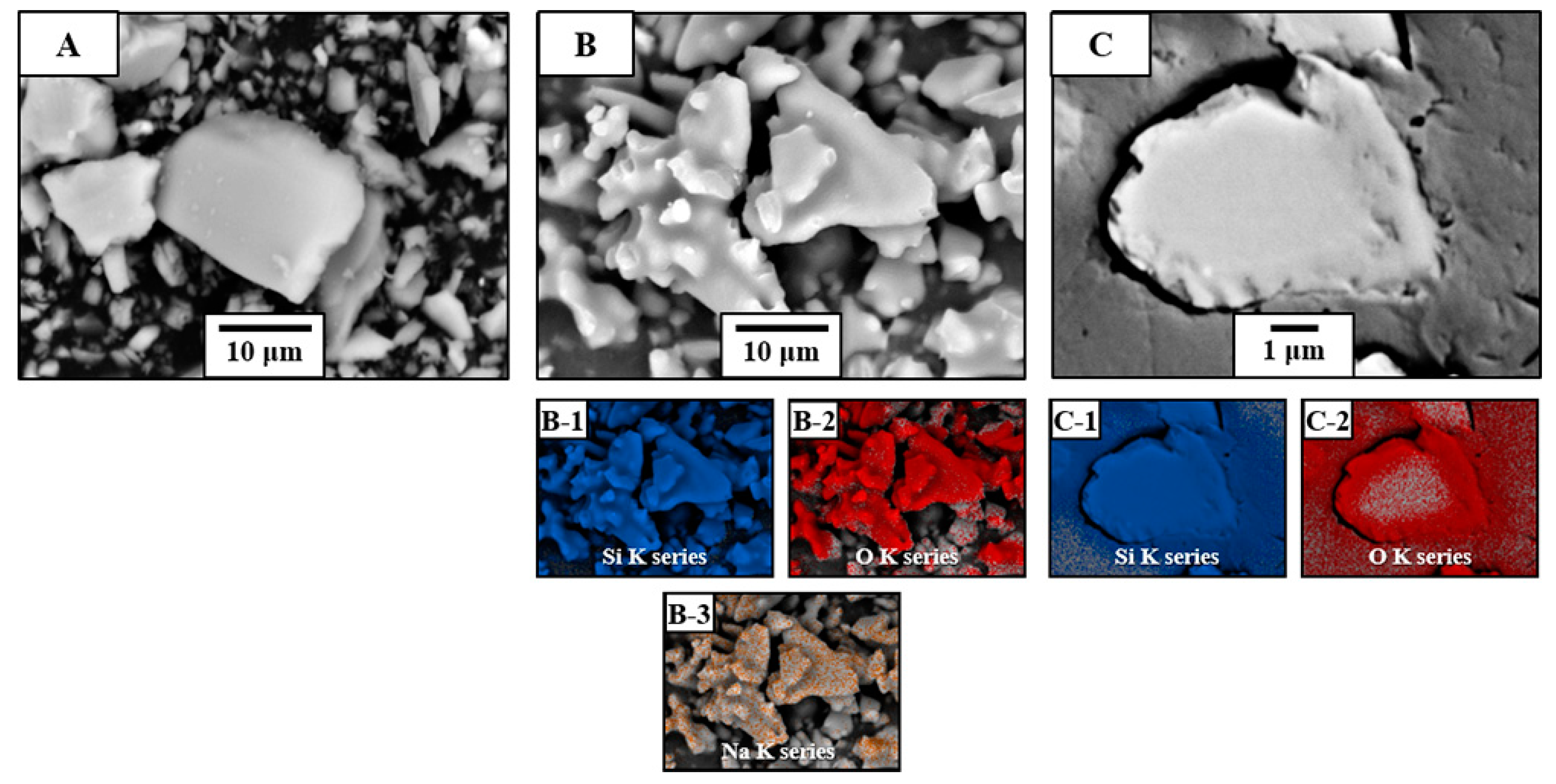
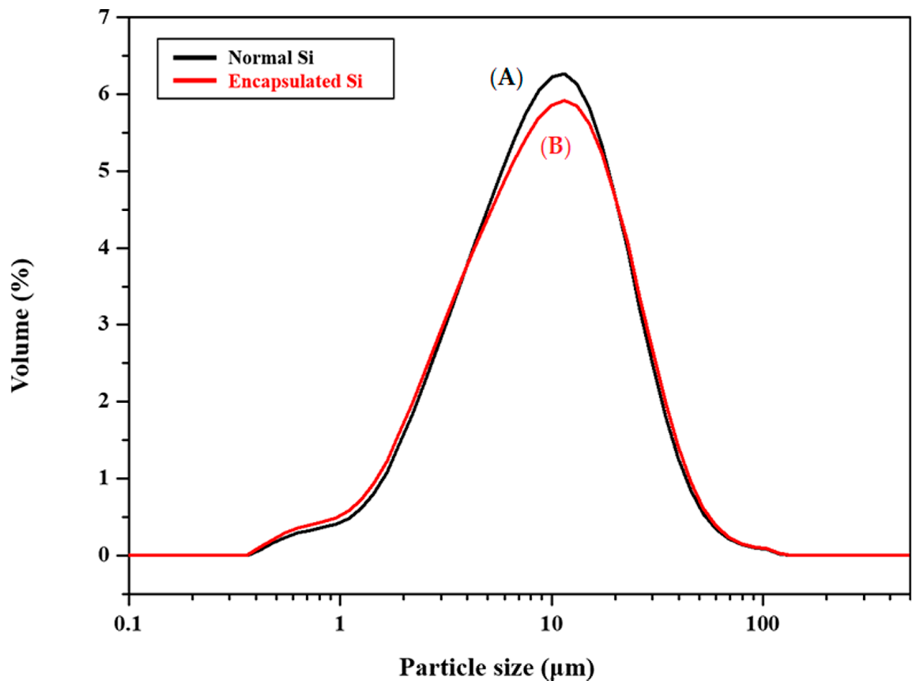
2.1. Healing Agent Powder Encapsulation Process

To produce a protective shell for the Si healing agents, the binary glassification process from our previous studies was employed [34,35,36]. This method involved the formation of a glass phase, which was synthesized through the sol-gel reaction and glassification between silicate and sodium alkoxide, resulting in a glassificated SiO2 shell around the particle surface [36]. The detailed encapsulation process is described in Figure 1. Prior to the encapsulation process, the healing agent—silicon powder (Si, 325 mesh, 99% trace metal basis, Sigma-Aldrich, Saint Louis, MO, USA)—was dispersed in methyl alcohol (methanol, CH3OH, 99.5%, Samchun Chemicals, Seoul, Korea) using an ultrasonic bath (Branson 3510, Branson Ultrasonics Corporation, Danbury, CT, USA) for 30 min at 60 °C. The binary precursor solution was composed of tetraethyl orthosilicate (TEOS, Si(OC2H5)4, 98%, Sigma-Aldrich) and sodium methoxide solution (NaOMe, CH3ONa, 25 wt% in methanol, Sigma-Aldrich) as SiO2 and Na2O precursors, respectively.
The composition of the binary precursor solution followed our previous studies [34,35,36] with the molar ratio of 0.18:1.5 of TEOS and NaOMe, which was stirred for just a few minutes at room temperature. Then, the dispersed healing agent was added to the solution, and the mixture was left in an oven at 80 °C for 24 h to undergo the hydrolysis reaction. The resulting gel was vacuum-filtered using filter paper (F1001, CHMLAB, Barcelona, Spain) and washed to remove unreacted precursors with deionized water. Finally, to produce a uniform glassificated SiO2 shell, the coated Si powders were heat-treated at 1000 °C for 60 min in air.
The morphology of the encapsulated healing agents was investigated using scanning electron microscopy (SEM, JSM-5610, JEOL, Tokyo, Japan). In particular, to observe the cross-section of the microscale powder, the encapsulated powder was cold vacuum mounted by resin and finely polished with 1 μm diamond paste and polishing cloth. The polished area was Au-coated by a sputtering system (108 Auto Sputter Coater, Cressington, UK), which prevented charging during SEM observation. The composition was also analyzed by an energy dispersive spectrometer (EDS, Oxford Instruments, Abingdon, UK) and X-ray diffractometer (XRD, Mini Flex II, Rigaku, Japan) using Cu Kα radiation (λ = 1.5418 Å) with the operation condition of a step size 0.02° and a scan speed of 3°/min. The particle sizes of healing agents before and after encapsulation were analyzed by laser diffraction (Mastersizer 2000 Hydro 2000S, Malvern Instruments, Herrenberg, Germany). The encapsulated particles were gently ground to prevent the encapsulation shell from crushing to submicron particles, then each sample (100 mg) was dispersed in deionized water using an ultrasonic bath.

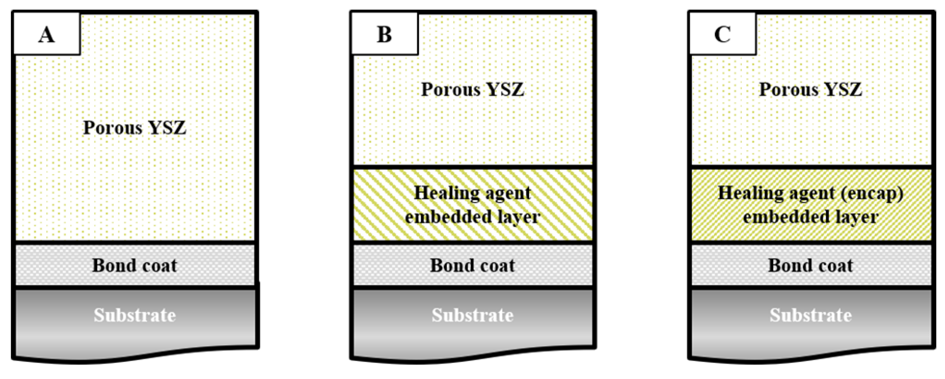
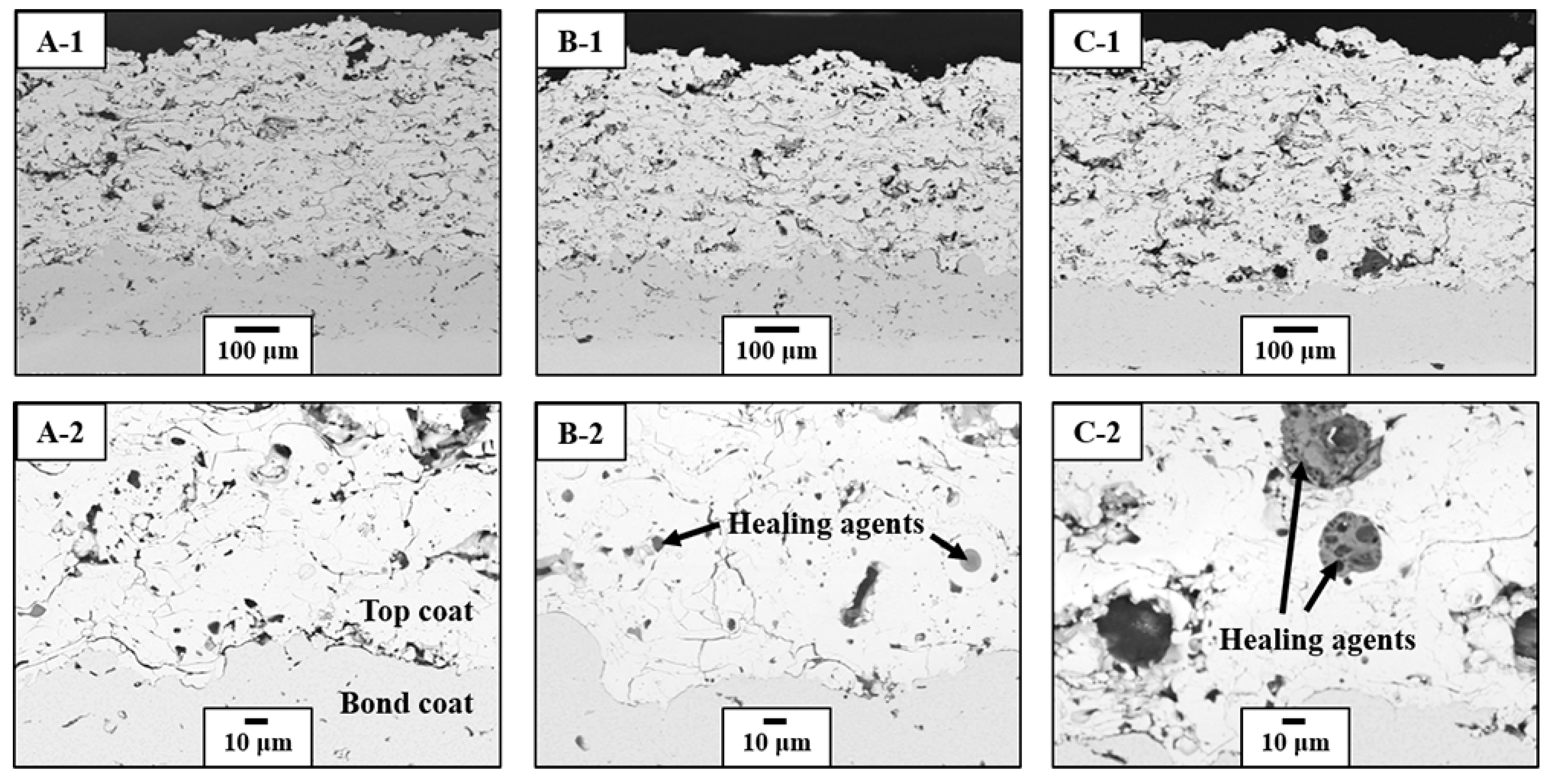
2.2. Coating Fabrication

In this study, the healing agents’ embedded buffer layer was introduced between the bond coat and conventional top coat as a crack-resisting layer, following the coating designs in Figure 2. Three types of coating specimens were prepared: each structure of a conventional TBC with a YSZ top coat (sample A), a crack-healing TBC with healing agents embedded in a buffer layer (sample B), and a crack-healing TBC with encapsulated healing agents (sample C), which are described in Figure 2A–C, respectively. A disk-shaped Ni-based superalloy (Nimonic 263, a nominal composition of Ni–20Cr–20Co–5.9Mo–0.5Al–2.1Ti–0.4Mn–0.3Si–0.06C, in wt%, Thyssen Krupp VDM, Werdohl, Germany) was used as a substrate, with dimensions of 25 mm in diameter and 5 mm in thickness. The substrate was sandblasted using Al2O3 powder (particle size: ≈ 420 μm) before bond coat fabrication, and the bond coat was deposited by high-velocity oxygen fuel (Diamond Jet-2600 DJM, Sulzer Metco Holding AG, Winterthur, Switzerland) methods with the thickness of 150–200 μm using AMDRY 9954 (Oerlikon Metco AG, Pfäffikon, Switzerland, nominal composition of Co–32Ni–21Cr–8Al–0.5Y in wt% and particle size of 11–63 μm). The buffer layer and top coat were fabricated by atmospheric plasma spray (APS, 9MB coating system, Sulzer Metco Holding AG) methods for thicknesses of 100–150 and 400–450 μm, respectively. METCO 204 C-NS (Oerlikon Metco AG, 8 wt% Y2O3 doped in ZrO2, particle size of 45–140 μm) feedstock was used for the top coat material. For the buffer layer, YSZ feedstock was blended with each normal Si and encapsulated Si powder. The healing agent and YSZ with a volume ratio of 10:90 were mechanically mixed through ball milling for 24 h. All employed top and bond coat fabrication parameters as suggested by the manufacturer; see Table 1.

2.3. Thermal Durability Evaluation and Analysis

Cyclic Thermal Fatigue (CTF) and Jet Engine Thermal Shock (JETS) tests were performed for the prepared specimens to investigate the crack-resisting behavior under thermal durability tests. First, for the CTF tests, the specimens were held in the furnace with a dwell time of 40 min at 1100 °C to impose a thermal fatigue condition and then naturally cooled in air for 20 min as one cycle [37]. The CTF tests were performed until the TBCs failed. The failure criterion was defined as more than 50% spallation area of the top coat. The JETS test was conducted to evaluate the thermal shock resistance using a system designed with a jet engine motif; the top coat surface was exposed for 25 s to a direct flame with a temperature of about 1400 °C, directly quenched by N2 gas for 25 s, and then followed by natural cooling for 1 min as one cycle [38]. The JETS tests were performed with the target of 2000 cycles, and the failure criteria were defined as a spallation area of more than 20% of the top coat or any cracking specifically at the interface between top and bond coats. At least three samples were tested for each thermal durability test. The microstructure before and after thermal durability tests was observed using SEM and EDS.
To investigate the crack-resisting behavior in detail, the as-coated specimens were cut and polished using SiC paper, and they were finely polished with 1 and 3 μm diamond pastes and polishing sheets. The polished cross-sectional area was artificially cracked using a microindenter (HM-114, Mitutoyo Corp., Kawasaki, Japan) with a Vickers tip with the loading level of 10 N for 30 s. The artificial cracks were located above the interface between the top and bond coats within the buffer layer. Then, they were heat-treated at 1000 °C for 100 h, and their healing reaction and detailed crack-resisting behavior were analyzed by SEM and EDS.

3. Results and Discussion

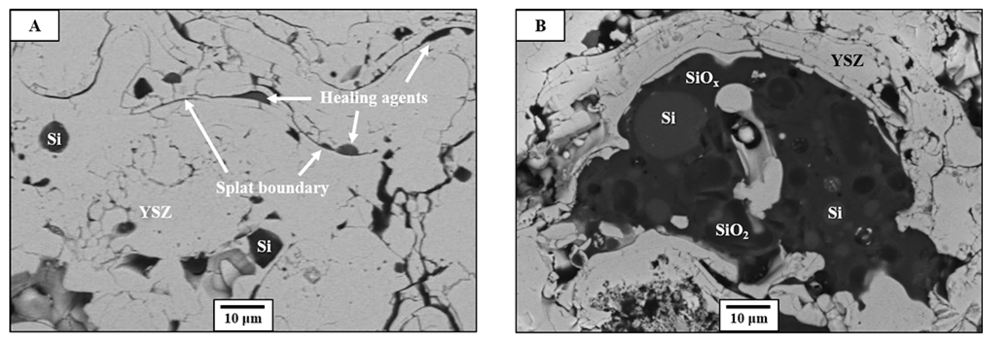
3.1. Protection of Healing Agents and Resistance Against Premature Oxidation

The microstructure of the Si healing agent powder before and after encapsulation is shown in Figure 3. Figure 3A,B shows the normal Si and encapsulated Si powder surface morphologies, respectively. Each number indicated the components’ intensity of Si, O, and Na from EDS mapping. Compared with the normal Si powder, the encapsulated powder had a relatively smooth surface morphology, which was evidence of a successful glassification process [36]. This morphology of glassificated shell implied that some agglomerated healing particles were covered by the glass shell immediately. The EDS mapping image shows that the encapsulated powder contained Na, which consisted of the shell from the glassification process. Further, encapsulated powders were mounted and fine-polished to observe the cross-sectional microstructure and more detailed shell morphology. Figure 3C shows the obtained microstructure and EDS mapping analysis. Encapsulated Si powder (light area) was surrounded by mounting resin (dark gray), showing unremarkable differences in the morphologies. The existence of the oxygen intensity indicated that the encapsulation process successfully produced the sub-micron-scale SiO2 shell (see Figure 3C-1,C-2). This suggested that the healing agents had a glassificated shell, which could protect the healing agent from premature oxidation during coating fabrication. Figure 4 shows the XRD analysis of the healing agents before and after the encapsulation processes. The cubic phase Si was observed in both specimens. After the encapsulation processes, a small cristobalite SiO2 peak was observed as a shell component. The results of microstructural and phase analyses indicated that both crystalline and amorphous SiO2 shells were well glassificated in the encapsulation process.
The particle size of the healing agents was analyzed for both the normal and encapsulated powders, the results of which are shown in Figure 5. The cumulative mass of the particles are shown in the Supplementary Table S1. Both samples showed similar size distributions, even after the encapsulation process. The encapsulated sample B showed that it contained more particles, with a particle size below 4 μm and above 20 μm, which resulted from the grinding after encapsulation and agglomeration, respectively. Similar particle size distributions indicated that the encapsulation process produced only a sub-micron-scale shell as well as the agglomerated particles, which corresponded to the microstructural observations in Figure 3B,C. In the APS process, the Si healing agent can be more easily oxidized than YSZ because it has a lower melting point and plasma-spray-forming temperature (10,000–15,000 K), resulting in the loss of its function [39]. However, the successfully produced submicron shell can protect healing agents, so it was expected that premature oxidation could be prevented. With the above discussion, the encapsulated healing agent was capable of being employed in the actual coating of specimens.

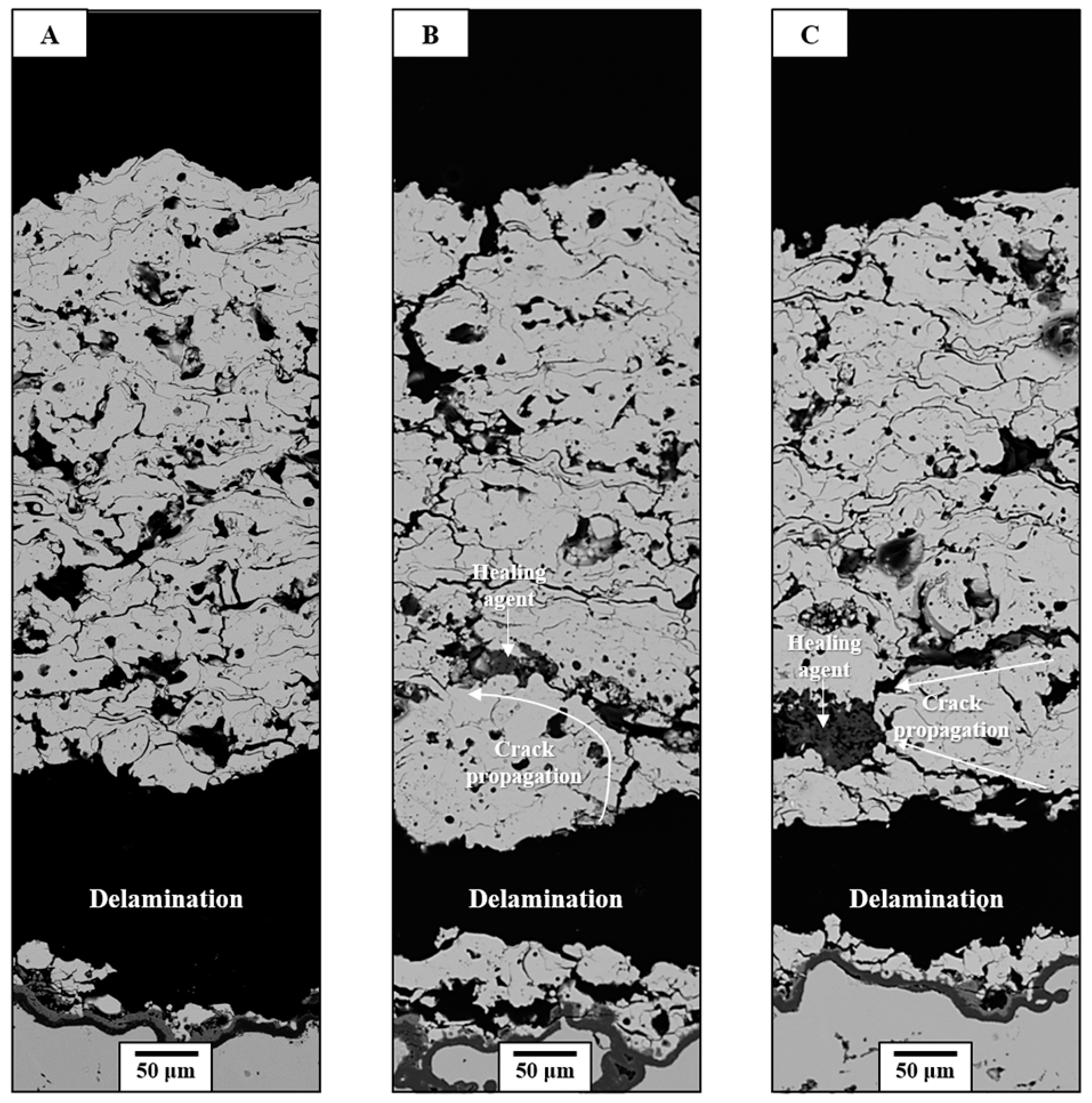
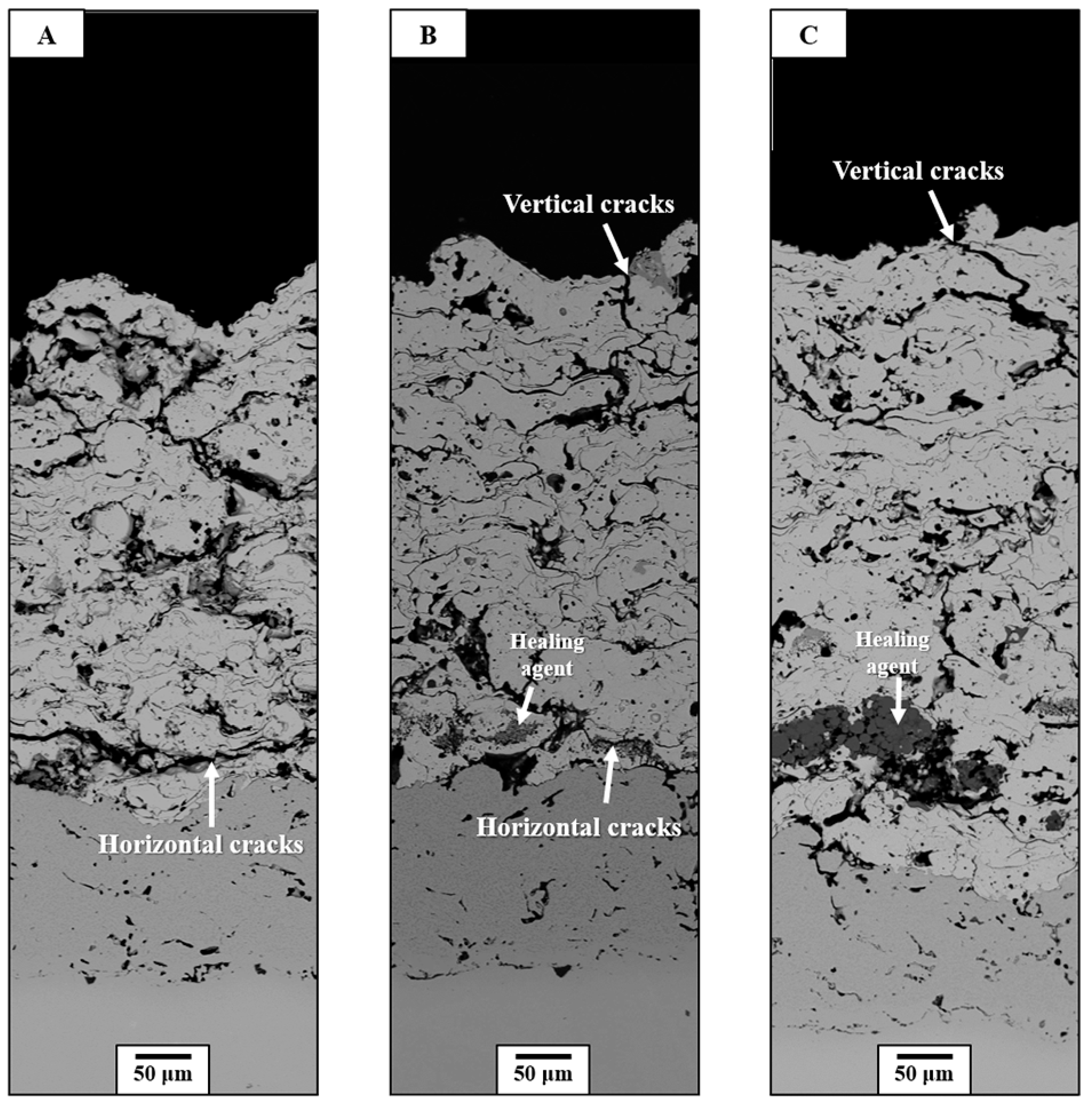
3.2. Thermal Durability Evaluation

All specimens were fabricated with the coating design shown in Figure 2. The cross-sectional microstructure of the as-coated specimens is shown in Figure 6. Each healing agent was embedded differently within the buffer layer, depending on the encapsulation process.
In Figure 6A-1,A-2, the conventional YSZ (sample A) showed a typical TBC microstructure fabricated by the APS method, showing splat boundaries, microcracks, and pores. All samples showed a sound bond coat and an interfacial condition without noticeable growth of a thermally grown oxide (TGO) layer.
The Si healing agent without encapsulation (sample B) had the morphology of an undulating shape and was embedded between the YSZ splats in the form of particles (Figure 6B-1,B-2). However, fewer Si healing agents were observed than the blended volume ratio in the as-prepared coating, which resulted from the evaporation of Si because of its low melting point [40].
The microstructure of the encapsulated healing-agent-embedded specimen (sample C) is shown in Figure 6C-1,C-2. The healing agents were embedded in the shape of the particles, which were similar to sample B. However, some of the healing agents were observed in the agglomerated condition, resulting from the encapsulation process (shown in Figure 6C-2). EDS-point mapping analysis of Figure 6C-1 is attached in Supplementary Figure S1 to prove the existence of the healing agent within the buffer layer. There was a relatively large number of embedded healing agents in comparison to normal Si (See Figure 6B-1,C-1. This result indicated that the encapsulation shell and larger particle size, as a result of agglomeration, reduced their evaporation [40].
Figure 7 shows the magnified microstructures of samples B and C with the component analysis around the healing agents. In Figure 7A, the healing agents in sample B were located between the YSZ splats, filling the empty splat boundaries. However, the encapsulated Si was in the shape of agglomerated powder as a kind of a cluster, which formed during heat treatment of the encapsulation process. The agglomerated healing particle consisted of pores, Si (light gray), partially oxidized Si (SiOx, gray), and shell component SiO2 (dark gray), which were based on the EDS-point analysis in Supplementary Figure S2. These results confirmed that the glassificated shell covered the healing agents well and protected them from premature oxidation during the APS process. The effects of healing agent distribution and morphology on the thermal durability and crack-healing behavior were investigated according to the encapsulation.
Figure 8 shows the cross-sectional microstructure around the delaminated area after CTF tests. During thermal cycling, different thermo-mechanical properties between the matrix and healing agent could develop stress, so only 10 vol% of healing agents was blended with YSZ to minimize the development of stress, which was founded in other previous studies [27,29].
Samples A, B, and C were delaminated after 1067, 1143, and 1103 cycles of CTF tests on average, respectively. Healing-agent-embedded TBCs (samples B and C) showed comparable thermal fatigue resistance to conventional YSZ. The continuous growth of TGO and some spinel oxides was observed at the interface between the top and bond coats, showing similar, common interfacial conditions. In sample A, small microcracks and pores were generated compared with the as-coated condition, while relatively thickened and enlarged cracks were generated within both buffer layers in samples B and C. Most of the cracks just above the bond coat grew horizontally because of the stress caused by CTE mismatch, which resulted in delamination, while the propagation of some cracks was inhibited by the healing agents. During the temperature change, the stress from CTE mismatch dominantly accelerated the thickening, linkage, and coalescence of cracks, resulted in the propagation of cracks. However, the healing agents inhibited propagation of these cracks because of their existence, which functioned as a ductile particle elaborated with an extrinsic toughening mechanism [41]. During thermal exposure, the healing agents were oxidized to SiO2, which had a glass transition temperature of about 1200 °C. Then, the shell components were glassificated and acted as ductile particles, resulting in the enhancement of fracture toughness by plastic deformation [42,43]. Although they showed similar thermal fatigue resistance, the slightly enhanced thermal durability in sample B can be explained by increased toughening probability, which resulted from a relatively uniform distribution and the fine size of the healing agents. However, sample C with encapsulated Si showed a slight decrease in thermal fatigue lifetime compared to the normal Si. This was because the concentration of agglomerated Si particles rather limited its healing function. To achieve noticeable enhancement of thermal fatigue lifetime, these limitations were countered by optimization of encapsulation process or postprocessing for uniform powder without agglomeration.
The cross-sectional microstructures after the JETS tests are shown in Figure 9. All the specimens survived 2000 cycles of JETS tests. The noticeable delamination or failure of TBCs was not observed in common. Even though they had similar lifetime performances, they had quite different microstructural degradation behaviors. In common, the bond coats showed sound conditions without evident oxidation and TGO growth, while severe TGO growth (including spinel phase) was observed after the CTF test. The most severe microstructural degradation was observed in sample A, which showed large crack formations because of the repeated thermal shocks. Vertical cracks initiated from the surface because of rapid volume shrinkage during N2 quenching, and they grew into large cracks through preexisting splats or pores under repeat of thermal shock, which was observed similarly in previous work [44]. Large horizontal cracks were generated near the interface because there was thermal stress from CTE mismatch between the top and bond coats, which could result in the failure of TBCs. Crack formation around the surface of the top coat was similarly observed in samples B and C. However, a different crack propagation was observed near the interface. Horizontal cracks formed and propagated to the healing agents during the JETS test. Although horizontal cracks were not clearly observed, the sub-micron-healing agent in sample B did not show noticeable crack-resisting behavior. This was because the crack scale had obviously larger openings and propagations than microscale Si healing particles, which embedded in the form of particles. On the other hand, the embedded Si particle, while agglomerated as healing agents in sample C, inhibited the rapid crack opening and propagation as a ductile particle under thermal shock conditions, which was not fully oxidized because of the relatively short thermal exposure period compared with the CTF test. Detailed crack-resisting mechanisms during the tests are elaborated on in Section 3.3.

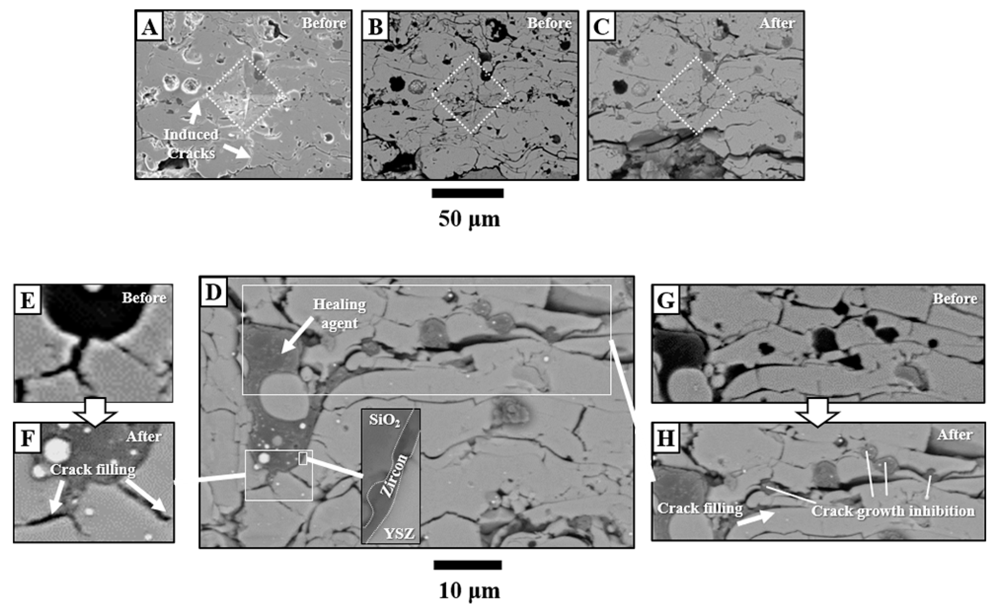
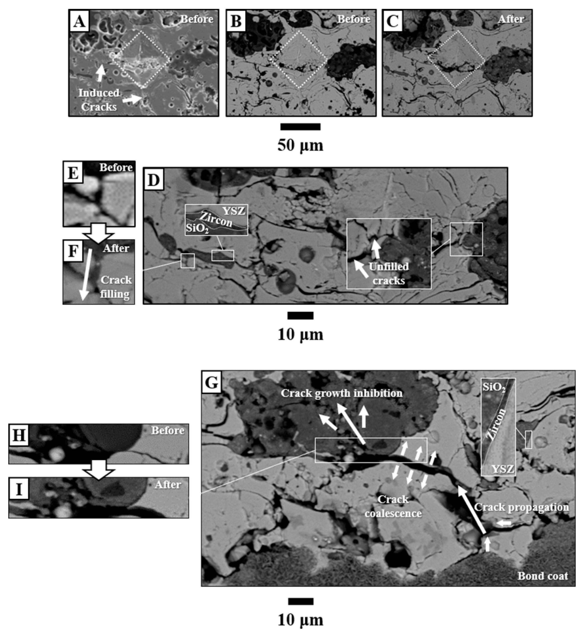
3.3. Crack-Resisting Mechanisms

Figure 10 shows the cross-sectional microstructure around the indentation imprints, which induced artificial cracks within the crack-healing buffer layer in sample B. The crack propagation-resisting behavior related to healing agents was investigated. The typical self-healing system was designed to seal nano- or microcracks before the occurrence of extensive damage. However, in the air-plasma sprayed TBC system, there were preexisting defects such as splat boundaries and microcracks, so crack-filling behavior against the opened defects was mainly investigated [27]. In Figure 10A–C, the dotted rhombus box indicated indentation imprints (about 50 μm diagonal), and emerged cracks were indicated by white arrows. Crack-filling behavior was observed in Figure 10E,F by the healing agents, which showed volume expansion because of oxidation. The formation of ZrSiO4 (zircon) evidenced new solid bonds between the YSZ matrix and Si healing agents, which could enhance the interfacial stability as well as heal the cracks by filling (see the magnified image in Figure 10D and EDS-point and mapping analysis in Supplementary Figure S3). Moreover, crack growth, like coalescence and/or linkage, was inhibited by the embedded healing agents, which can be observed within the YSZ splat boundaries in Figure 10G,H.
The cross-sectional microstructure of sample C is shown in Figure 11 to investigate the crack-resisting behavior of encapsulated healing agents. In Figure 11A–C, the dotted rhombus box and white arrows indicated the indentation imprints (about 50 μm diagonal) and emerged cracks around the healing agents, respectively. In the magnified microstructure of Figure 11D, solid bonding was formed, the behavior of which was similar to the unencapsulated healing agents in sample B. The cracks around the healing agents were filled and propagated no further, especially around the unagglomerated particles (Figure 11E,F). However, some small microcracks were not fully filled around the agglomerated healing agents because the protective shell accommodated the volume expansion by oxidation. Even though the microcracks were partially filled, it could still prevent severe crack propagation that could lead to catastrophic failure [45]. In Figure 11G, large cracks were initiated because of the abrupt stress resulting from the CTE mismatch and TGO growth between the top and bond coats. The volume expansion of healing agent could generate stress, but the agglomerated healing agents contained some pores as a kind of a cluster, which accommodated some extent of stress (see the Figure 11F). Therefore, it was considered that stress by expansion was not dominant compared to the stress by CTE mismatch and TGO growth. As shown in Figure 11H,I, the microcracks and splat boundary were thickened from the interface. However, these cracks, which can finally cause delamination, stopped growing by branching into small cracks within the agglomerated healing agents, observed commonly in sample C.
The crack-resisting behavior of Si healing agents can be elaborated on with the following three mechanisms: (i) healing agents that are located between splat boundaries form zircon as a new solid bonding, which enhances the resistance of tensile stress and results in less delamination of TBC; (ii) healing agents, with their partially unmelted shapes, can reduce the near-crack-tip stress as ductile particles and fill small cracks, preventing microcrack opening; and (iii) agglomerated healing agents above the interface between the top and bond coats can inhibit large crack propagation by branching into small cracks within the healing agents, although they cannot stop small crack openings through crack filling.
Based on the results above, repeating out-of-plane tensile stress can accumulate damage and cause coalescence and linkage of discontinuities such as microcracks and splat boundaries. Sample B has a relatively uniform distribution of healing agents with a fine particle size, so the healing agent can effectively stop the crack opening and form new solid bonding all over the buffer layer, which results in thermal durability and, especially, thermal fatigue resistance. On the other hand, large crack propagations, because of the abrupt stress from rapid temperature changes during the JETS test, were blocked by the agglomerated healing agent above the interface in sample C. This elaborates on the enhanced thermal shock resistance of sample C, as it has a relatively more sound microstructure than sample B without noticeable large cracks after the JETS tests.
However, even though the healing agents filled some cracks and blocked the crack opening successfully, they cannot fully fill the microcracks around them nor can they fill large cracks because of their poor fluidity [46,47]. This can be overcome by increasing the fluidity or decreasing the viscosity at the operating temperature by doping some appropriate contents or modifying the encapsulation process [27]. Furthermore, the optimization of particle size distribution and volume ratio of healing agents will be studied in future work.

4. Conclusions

In this work, a novel TBC system with a buffer layer embedded with Si-based crack-healing agents has been developed and evaluated. Using thermal durability tests, the crack-resisting behaviors and mechanisms of Si, and encapsulated Si, and the related mechanisms are presented. The main contributions are as follows.
  • An encapsulation process is developed to cover the healing agents, preventing them from premature oxidation or evaporation during coating fabrication.
  • The TBCs with a crack-healing buffer layer show comparable thermal durability in both the CTF and JETS tests.
  • Crack-resisting mechanisms are elaborated on depending on the distribution and shape of healing agents through the observation of crack-healing behaviors.

Supplementary Materials

The following are available online at https://www.mdpi.com/2079-6412/9/6/358/s1, Figure S1: EDS mapping analysis around the healing agents in as-coated samples from Figure 6C-1; Figure S2: EDS point-analysis around the healing agents in as-coated samples from Figure 7A,B; Figure S3: EDS point- and mapping analysis around the healing agents after heat treatment from the magnified image in Figure 10C; Table S1: Particle diameters at 10%, 50%, and 90% of the cumulative mass of (A): normal Si, and (B) encapsulated Si from Figure 5.

Author Contributions

Conceptualization, D.S., T.S. and Y.-G.J.; Methodology, D.S., T.S., G.L., Y.-G.J. and J.Z.; Formal analysis, D.S. and G.L.; Investigation, D.S., T.S., G.L., Y.-G.J., B.-G.C., I.-S.K. and J.Z.; Writing-Original Draft Preparation, D.S.; Writing-Review and Editing, D.S., T.S., U.P., Y.-G.J., B.-G.C., I.-S.K. and J.Z.; Supervision, T.S., U.P. and Y.-G.J.; Project Administration, T.S., U.P. and Y.-G.J.; Funding Acquisition, T.S., U.P. and Y.-G.J.

Funding

This research was funded by “Human Resources Program in Energy Technology (No. 20194030202450)” and “Power Generation & Electricity Delivery grant (No. 20181110100310)” of the Korea Institute of Energy Technology Evaluation and Planning (KETEP); a granted financial resource from the Ministry of Trade, Industry & Energy, Korea; and by Fundamental Research Program of the Korean Institute of Materials Science (KIMS, No. PNK5620).

Conflicts of Interest

The authors declare no conflict of interest.

References

  1. Miller, R.A. Current status of thermal barrier coatings—An overview. Surf. Coat. Technol. 1987, 30, 1–11. [Google Scholar] [CrossRef]
  2. Padture, N.P.; Gell, M.; Jordan, E.H. Thermal barrier coatings for gas—Turbine engine applications. Science 2002, 296, 280–284. [Google Scholar] [CrossRef]
  3. Evans, A.G.; Mumm, D.; Hutchinson, J.; Meier, G.; Pettit, F. Mechanisms controlling the durability of thermal barrier coatings. Prog. Mater. Sci. 2001, 46, 505–553. [Google Scholar] [CrossRef]
  4. Clarke, D.; Levi, C. Materials design for the next generation thermal barrier coatings. Annu. Rev. Mater. Res. 2003, 33, 383–417. [Google Scholar] [CrossRef]
  5. Strangman, T.E. Thermal barrier coatings for turbine airfoils. Thin Solid Films 1985, 127, 93–106. [Google Scholar] [CrossRef]
  6. Haynes, J.A.; Ferber, M.; Porter, W. Thermal cycling behavior of plasma—Sprayed thermal barrier coatings with various MCrAlX bond coats. J. Therm. Spray Technol. 2000, 9, 38. [Google Scholar] [CrossRef]
  7. Zhou, C.; Wang, N.; Wang, Z.; Gong, S.; Xu, H. Thermal cycling life and thermal diffusivity of a plasma—Sprayed nanostructured thermal barrier coating. Scr. Materialia 2004, 51, 945–948. [Google Scholar] [CrossRef]
  8. Cao, X.; Vassen, R.; Stoever, D. Ceramic materials for thermal barrier coatings. J. Eur. Ceram. Soc. 2004, 24, 1–10. [Google Scholar] [CrossRef]
  9. Vaßen, R.; Kerkhoff, G.; Stöver, D. Development of a micromechanical life prediction model for plasma sprayed thermal barrier coatings. Mater. Sci. Eng. A 2001, 303, 100–109. [Google Scholar] [CrossRef]
  10. Hasselman, D.; Johnson, L.F.; Bentsen, L.D.; SYED, R.; LEE, H.L.; SWAIN, M.V. Thermal diffusivity and conductivity of dense polycrystalline Zr0. Am. Ceram. Soc. Bull 1987, 66, 799–806. [Google Scholar]
  11. Hayashi, H.; Saitou, T.; Maruyama, N.; Inaba, H.; Kawamura, K.; Mori, M. Thermal expansion coefficient of yttria stabilized zirconia for various yttria contents. Solid State Ion. 2005, 176, 613–619. [Google Scholar] [CrossRef]
  12. Cheng, J.; Jordan, E.; Barber, B.; Gell, M. Thermal/residual stress in an electron beam physical vapor deposited thermal barrier coating system. Acta Mater. 1998, 46, 5839–5850. [Google Scholar] [CrossRef]
  13. Pan, D.; Chen, M.; Wright, P.; Hemker, K. Evolution of a diffusion aluminide bond coat for thermal barrier coatings during thermal cycling. Acta Mater. 2003, 51, 2205–2217. [Google Scholar] [CrossRef]
  14. Czech, N.; Esser, W.; Schmitz, F. Effect of environment on mechanical properties of coated superalloys and gas turbine blades. Mater. Sci. Technol. 1986, 2, 244–249. [Google Scholar] [CrossRef]
  15. Tamura, M.; Takahashi, M.; Ishii, J.; Suzuki, K.; Sato, M.; Shimomura, K. Multilayered thermal barrier coating for land—Based gas turbines. J. Therm. Spray Technol. 1999, 8, 68–72. [Google Scholar] [CrossRef]
  16. Sumner, I.; Ruckle, D. Development of improved—Durability plasma sprayed ceramic coatings for gas turbine engines. In Proceedings of the 16th Joint Propulsion Conference, Hartford, CT, USA, 30 June–2 July 1980. [Google Scholar]
  17. Chang, G.C.; Phucharoen, W.; Miller, R.A. Behavior of thermal barrier coatings for advanced gas turbine blades. Surf. Coat. Technol. 1987, 30, 13–28. [Google Scholar] [CrossRef]
  18. Chang, G.; Phucharoen, W.; Miller, R. Finite element thermal stress solutions for thermal barrier coatings. Surf. Coat. Technol. 1987, 32, 307–325. [Google Scholar] [CrossRef]
  19. Taylor, T.A. Thermal barrier coating for substrates and process for producing it. U.S. Patent 5,073,433, 17 December 1991. [Google Scholar]
  20. Duvall, D.; Ruckle, D. Ceramic thermal barrier coatings for turbine engine components. In Proceedings of the ASME 1982 International Gas Turbine Conference and Exhibit, London, UK, 18–22 April 1982. [Google Scholar]
  21. Musil, J.; Fiala, J. Plasma spray deposition of graded metal—Ceramic coatings. Surf. Coat. Technol. 1992, 52, 211–220. [Google Scholar] [CrossRef]
  22. Schulz, U.; Leyens, C.; Fritscher, K.; Peters, M.; Saruhan-Brings, B.; Lavigne, O.; Dorvaux, J.-M.; Poulain, M.; Mévrel, R.; Caliez, M. Some recent trends in research and technology of advanced thermal barrier coatings. Aerosp. Sci. Technol. 2003, 7, 73–80. [Google Scholar] [CrossRef]
  23. Johnson, C.; Ruud, J.; Bruce, R.; Wortman, D. Relationships between residual stress, microstructure and mechanical properties of electron beam—Physical vapor deposition thermal barrier coatings. Surf. Coat. Technol. 1998, 108, 80–85. [Google Scholar] [CrossRef]
  24. Padture, N.; Schlichting, K.; Bhatia, T.; Ozturk, A.; Cetegen, B.; Jordan, E.; Gell, M.; Jiang, S.; Xiao, T.; Strutt, P. Towards durable thermal barrier coatings with novel microstructures deposited by solution—Precursor plasma spray. Acta Mater. 2001, 49, 2251–2257. [Google Scholar] [CrossRef]
  25. Kassner, H.; Siegert, R.; Hathiramani, D.; Vassen, R.; Stoever, D. Application of suspension plasma spraying (SPS) for manufacture of ceramic coatings. J. Therm. Spray Technol. 2008, 17, 115–123. [Google Scholar] [CrossRef]
  26. Guignard, A.; Mauer, G.; Vaßen, R.; Stöver, D. Deposition and characteristics of submicrometer—Structured thermal barrier coatings by suspension plasma spraying. J. Therm. Spray Technol. 2012, 21, 416–424. [Google Scholar] [CrossRef]
  27. Derelioglu, Z.; Carabat, A.; Song, G.; van der Zwaag, S.; Sloof, W. On the use of B-alloyed MoSi2 particles as crack healing agents in yttria stabilized zirconia thermal barrier coatings. J. Eur. Ceram. Soc. 2015, 35, 4507–4511. [Google Scholar] [CrossRef]
  28. Carabat, A.; Meijerink, M.; Brouwer, J.; Kelder, E.; van Ommen, J.; van der Zwaag, S.; Sloof, W. Protecting the MoSi2 healing particles for thermal barrier coatings using a sol-gel produced Al2O3 coating. J. Eur. Ceram. Soc. 2018, 38, 2728–2734. [Google Scholar] [CrossRef]
  29. Chen, Y.; Zhang, X.; van der Zwaag, S.; Sloof, W.G.; Xiao, P. Damage evolution in a self-healing air plasma sprayed thermal barrier coating containing self-shielding MoSi2 particles. J. Am. Ceram. Soc. 2019, 102, 16313. [Google Scholar] [CrossRef]
  30. Ouyang, T.; Fang, X.; Zhang, Y.; Liu, D.; Wang, Y.; Feng, S.; Zhou, T.; Cai, S.; Suo, J. Enhancement of high temperature oxidation resistance and spallation resistance of SiC-self-healing thermal barrier coatings. Surf. Coat. Technol. 2016, 286, 365–375. [Google Scholar] [CrossRef]
  31. Scott, H. Phase relationships in the zirconia-yttria system. J. Mater. Sci. 1975, 10, 1527–1535. [Google Scholar] [CrossRef]
  32. Veytizou, C.; Quinson, J.-F.; Valfort, O.; Thomas, G. Zircon formation from amorphous silica and tetragonal zirconia: Kinetic study and modelling. Solid State Ion. 2001, 139, 315–323. [Google Scholar] [CrossRef]
  33. Nozahic, F.; Monceau, D.; Estournès, C. Thermal cycling and reactivity of a MoSi2/ZrO2 composite designed for self-healing thermal barrier coatings. Mater. Des. 2016, 94, 444–448. [Google Scholar] [CrossRef]
  34. Kim, E.-H.; Lee, W.-R.; Jung, Y.-G.; Lee, C.-S. A new binder system for preparing high strength inorganic molds in precision casting. Mater. Chem. Phys. 2011, 126, 344–351. [Google Scholar] [CrossRef]
  35. Kim, E.-H.; Cho, G.-H.; Jung, Y.-G.; Kim, I.-S.; Jo, C.-Y.; Lee, J.-S. Adhesion phenomena between particles according to the content of organic binder in core for thin-wall casting. J. Nanosci. Nanotechnol. 2014, 14, 8048–8052. [Google Scholar] [CrossRef]
  36. Jung, Y.-G.; Tumenbayar, E.; Choi, H.-H.; Park, H.-Y.; Kim, E.-H.; Zhang, J. Effects of alumina precursor species in a ternary—Phase binder system on the strength of sand mold. Ceram. Int. 2018, 44, 2223–2230. [Google Scholar] [CrossRef]
  37. Park, H.-M.; Jun, S.-H.; Lyu, G.; Jung, Y.-G.; Yan, B.-I.; Park, K.-Y. Thermal durability of thermal barrier coatings in furnace cyclic thermal fatigue test: Effects of purity and monoclinic phase in feedstock powder. J. Korean Ceram. Soc. 2018, 55, 608–617. [Google Scholar] [CrossRef]
  38. Park, K.-Y.; Yang, B.-I.; Jeon, S.-H.; Park, H.-M.; Jung, Y.-G. Variation of thermal barrier coating lifetime characteristics with thermal durability evaluation methods. J. Therm. Spray Technol. 2018, 27, 1436–1446. [Google Scholar] [CrossRef]
  39. Laha, T.; Agarwal, A.; McKechnie, T.; Seal, S. Synthesis and characterization of plasma spray formed carbon nanotube reinforced aluminum composite. Mater. Sci. Eng. A 2004, 381, 249–258. [Google Scholar] [CrossRef]
  40. Koch, D.; Mauer, G.; Vaßen, R. Manufacturing of composite coatings by atmospheric plasma spraying using different feed-stock materials as YSZ and mosi 2. J. Therm. Spray Technol. 2017, 26, 708–716. [Google Scholar] [CrossRef]
  41. Ritchie, R.O. Mechanisms of fatigue—Crack propagation in ductile and brittle solids. Int. J. Fract. 1999, 100, 55–83. [Google Scholar] [CrossRef]
  42. Ponnusami, S.A.; Turteltaub, S.; van der Zwaag, S. Cohesive-zone modelling of crack nucleation and propagation in particulate composites. Eng. Fract. Mech. 2015, 149, 170–190. [Google Scholar] [CrossRef]
  43. Ojovan, M.I. Glass formation in amorphous SiO2 as a percolation phase transition in a system of network defects. J. Exp. Theor. Phys. Lett. 2004, 79, 632–634. [Google Scholar] [CrossRef]
  44. Song, D.; Paik, U.; Guo, X.; Zhang, J.; Woo, T.-K.; Lu, Z.; Jung, S.-H.; Lee, J.-H.; Jung, Y.-G. Microstructure design for blended feedstock and its thermal durability in lanthanum zirconate based thermal barrier coatings. Surf. Coat. Technol. 2016, 308, 40–49. [Google Scholar] [CrossRef] [Green Version]
  45. Nozahic, F.; Estournès, C.; Carabat, A.L.; Sloof, W.G.; Van Der Zwaag, S.; Monceau, D. Self-healing thermal barrier coating systems fabricated by spark plasma sintering. Mater. Des. 2018, 143, 204–213. [Google Scholar] [CrossRef] [Green Version]
  46. Seward, T.P., III; Vascott, T. High Temperature Glass Melt Property Database for Process Modeling; Wiley-American Ceramic Society: Westerville, OH, USA, 2005. [Google Scholar]
  47. Fluegel, A. Glass viscosity calculation based on a global statistical modelling approach. Glass Technol.-Eur. J. Glass Sci. Technol. Part A 2007, 48, 13–30. [Google Scholar]
Figure 1. Schematic diagram of the encapsulation process for healing agents.
Coatings 09 00358 g001
Figure 2. Schematic diagram of coating designs: (A) a conventional thermal barrier coating (TBC) (sample A), (B) a crack-healing TBC with a buffer layer (sample B), and (C) a crack-healing TBC with encapsulated agents (sample C). YSZ = yttria-stabilized zirconia.
Coatings 09 00358 g002
Figure 3. Powder morphology and component distribution of healing agent: (A) normal Si powder, (B) Si powder encapsulated by a binary system, and (C) magnified cross section of Si powder encapsulated by a binary system. Each number indicates energy dispersive spectrometer (EDS) mapping results of Si (B-1,C-1), O (B-2,C-2), and Na (B-3), respectively.
Coatings 09 00358 g003
Figure 4. X-ray diffractometer (XRD) analysis results of Si powder encapsulated by a binary system: (A) normal Si, and (B) Si powder encapsulated by a binary system.
Coatings 09 00358 g004
Figure 5. The particle size distribution of (A) normal Si, and (B) Si powder encapsulated by a binary system.
Coatings 09 00358 g005
Figure 6. Cross-sectional microstructures of as-coated samples: (A-1,A-2) a conventional TBC (sample A), (B-1,B-2) a crack-healing TBC with a buffer layer (sample B), and (C-1,C-2) a crack-healing TBC with encapsulated agents (sample C). Each number indicates the magnification of (100×) and (500×), respectively.
Coatings 09 00358 g006
Figure 7. Magnified microstructure around the healing agent in as-coated samples: (A) sample B, and (B) sample C.
Coatings 09 00358 g007
Figure 8. Cross-sectional microstructures after CTF tests: (A) sample A, (B) sample B, and (C) sample C.
Coatings 09 00358 g008
Figure 9. Cross-sectional microstructures after JETS tests: (A) sample A, (B) sample B, and (C) sample C.
Coatings 09 00358 g009
Figure 10. Microstructure around the indentation imprints in sample B before and after heat treatment. Microstructures of the as-coated sample are shown in (A), (B), (E), and (G), and those after heat treatment are shown in (C), (D), (F), and (H).
Coatings 09 00358 g010
Figure 11. Microstructure around the indentation imprints in sample C before and after heat treatment. Microstructures of the as-coated sample are shown in (A), (D), and (G), and those after heat treatment are shown in (B), (C), (E), (F), and (H).
Coatings 09 00358 g011
Table 1. Parameters of air plasma spraying.
ParameterGun TypeCurrent
(A)
Primary Gas, Ar
(L/min)
Secondary Gas, H2
(L/min)
Powder Feed Rate
(g/min)
Spray Distance
(mm)
Gun Speed
(mm/s)
Top coatMETCO-3MB48023.5965.66340804

