Article

The Effects of Ti Additions and Deposition Parameters on the Structural and Mechanical Properties of Stainless Steel-Nitride Thin Films

by
Faisal I. Alresheedi
1 and
James E. Krzanowski
2,*
1
Physics Department, University of New Hampshire, Durham, NH 03824, USA
2
Mechanical Engineering Department, University of New Hampshire, Durham, NH 03824, USA
*
Author to whom correspondence should be addressed.
Coatings 2019, 9(5), 329; https://doi.org/10.3390/coatings9050329
Submission received: 1 April 2019 / Revised: 9 May 2019 / Accepted: 16 May 2019 / Published: 21 May 2019

Abstract

:
This study examines the structure and properties of stainless steel coatings deposited to incorporate large concentrations of nitrogen along with varying amounts of titanium. Deposition was carried out using magnetron co-sputtering of stainless steel and titanium from separate targets in a mixed Ar/N2 gas atmosphere. Composition analysis by X-ray photoelectron spectroscopy showed that while films with up to 4 at.% Ti exhibited little change in nitrogen content (compared to films deposited without Ti) and remained sub-stoichiometric with respect to N content. Films with 7–8 at.% Ti had a higher N level and further increasing the Ti level to 11–12 at.% resulted in stoichiometric N levels. X-ray diffraction showed that the films all had a nominally FCC structure with no additional phases. However, the peak locations for the (111) and (200) reflections indicated a distorted lattice characteristic of the S-phase, with calculated c/a values ranging from 1.007 to 1.033. The Ti additions, along with the corresponding increase in N content, helped reduce the extent of lattice distortion. The film microstructure of the higher (11–12 at.%) Ti films also showed higher density, lower surface roughness, and a finer grain structure. As a result, these films had a higher hardness compared to the sub-stoichiometric films, with hardness levels in the range of 18–23 GPa, typical of transition metal nitrides coatings.

1. Introduction

Austenitic stainless steels such as AISI 304 demonstrate excellent corrosion resistance and relatively good levels of strength and toughness, which makes them attractive and widely used engineering materials. However, they have poor wear resistance, resulting in short lifetimes that limit their applications where extensive surface interactions are present. Therefore, surface treatment processes have been developed to improve the wear resistance and hardness of stainless steels [1,2,3,4,5,6,7,8,9,10,11,12]. These treatments use plasma-based methods to create a nitrogen-rich surface layers that exhibits high hardness and wear resistance. However, process temperatures are often limited to about 450 °C in order to avoid precipitation of CrN, which has been shown to reduce corrosion resistance [2]. At lower processing temperatures, a nitrogen-supersaturated phase is formed that is commonly called the “S-phase” or “expanded austenite” [13,14,15,16,17]. Experimentally, the S-phase is characterized by the anomalous position of the (200) reflection, giving the result that effective lattice parameters are described by the relation a111 = a220 = a311 < a200 [16]. The crystal structure that would produce such a result has still not been unambiguously identified, despite consideration of a large number of candidate structures [16] that were based on small distortions of the cubic fcc-Rocksalt structure. Recent research has shown that the observed diffraction anomalies may be due to both the presence of stacking faults and elastic and plastic anisotropy effects [18,19]. Despite its elusive structure, the formation of the S-phase on the surface of stainless steels is a useful method of improving hardness and wear resistance. However, the hardness of the S-phase layer, typically ~10–15 GPa [2,3,4,9,10] is still lower than what is commonly obtained in transition metal nitrides such as TiN, which in thin-film form can reach over 30 GPa [20].
As an alternative to plasma-based methods for nitriding stainless steels, reactive magnetron sputtering can be used to deposit N-enriched “stainless steel-nitride (SSN)” films [21,22,23,24,25,26,27,28]. Results have shown that S-phase structured films with hardness levels similar to plasma nitrided samples can be obtained [28]. However, in the sputtering method, the metallic component is not limited to common stainless steel alloys, and additional metallic constituents can be added by co-sputtering from multiple targets. Alloying stainless steels nitrides with transition metal nitrides such as titanium nitride (TiN) to create hybrid SSN-TiN films has the potential to create coatings that exhibits higher hardness and improved wear resistance. In this study, a systematic investigation is undertaken to examine the effects of adding Ti during sputtering, as well as optimizing the deposition parameters for these new films, and produce hybrid coatings combining stainless steels nitride (SSN) and titanium nitride (TiN). The extent of Ti additions is limited here to about 12 at.%, effectively maintaining the stainless steel elements as the main components of the coatings. The deposition temperatures were chosen to span the range between room temperature and the typical maximum that can be used before phase decomposition into metallic and nitride phases [28]. A substrate bias of −100 to −140 V was used for optimization of hardness without creating excessive stress levels. The composition, structure, grain morphology, and mechanical properties of these films are reported below.

2. Materials and Methods

Commercial targets of AISI 304 stainless steel (nominal composition: 8 wt.% Ni, 18 wt.% Cr and 74 wt.% Fe) and titanium (99.99 at.%) were used for deposition onto silicon wafers in a high-vacuum system (base pressure of 10−6 torr (1.3 × 10⁻⁴ Pa)) by magnetron sputtering. Deposition of the co-sputtered films from the stainless steel/titanium targets was carried out in a mixed Ar + N2 gas mixture with flowrates of 20 sccm Ar and 5 sccm N2 at 0.67 Pa. The substrate-to-target distance in the deposition of these films was approximately 9 cm. For all samples, a bond layer of metallic stainless steel was first deposited to a thickness of approximately 50 nm at a bias of −50 V. Mass flow controllers were used to set the flow rates of a mixed gas (argon and nitrogen) for SS-Ti-N. A radio frequency (rf) power supply was used for both sputter targets, which were 50 mm in diameter. During deposition, the substrate holder was held at a temperature ranging from room temperature to 350 °C. Throughout each process, a Sycon Instruments, Inc. (East Syracuse, NY, USA), STM-100M/F rate monitor and quartz crystal oscillator were used to monitor the deposition rate, although film thickness measurements presented here were determined from SEM cross-section images.
X-ray diffraction (XRD-6100, Shimadzu, Columbia, MD, USA) was used to study the crystal structure of the films and was conducted on a Shimadzu 6100 system. The system was equipped with a CuKα radiation source (λ = 0.15406 nm) and a graphite diffracted beam monochromator. The spectra were analyzed using the Jade 9 (Materials Data, Inc., Livermore, CA, USA) software program. Scans were run in two separate 2θ ranges, 30°–65° and 70°–120°, in order to avoid the large (400) Si substrate peak. Additional X-ray diffraction studies were done with a Bruker, Inc. area-detector system (Vantec-500, Bruker Inc., Madison, WI, USA) using monochromated CoKα radiation.
Film compositions were evaluated by X-ray photoelectron spectroscopy (XPS Axis HSi, Kratos Analytical, Manchester, UK), allowing the determination of the atomic percentage of each element. The analysis was carried out using a monochromatic MgKα X-ray source operating at 15 kV and 10 mA. During XPS runs, the acquisition parameters that were used were an energy range from 0 to 1200 eV, a step size of 1 eV, a dwell time of 200 ms and a pass energy of 160 eV. Prior to the analysis, samples were ion-etched in the XPS using a 4 keV Ar+ ion beam in order to remove surface contaminants. The peaks analyzed were Fe 2p, Ti 2p, Cr 2p, Ni 2p, O 1s and N 1s. The error in nitrogen concentration measurement by XPS is estimated as ±2–4 at.%. Cross-section samples for SEM evaluation were prepared by scoring and fracturing the Si substrate, and then examining the samples in a Tescan Lyra FIB-SEM system (Tescan, Inc., Brno, Czechia) operating at 6 keV. Images were acquired using the secondary electron mode and were used to evaluate film microstructure as well as measure film thickness.
The hardness of the films was first measured using a micro-indentation instrument equipped with a Knoop indenter and a set for a 10-g indentation load. However, thickness of most of the films was too low for accurate measurements (due to substrate effects), so these results were primarily used as a screening test to select films for further testing using nano-indentation. Based on this initial study, nano-identation tests were carried out on samples in groups 2–4 (see Table 1) at deposition temperatures ranging from 150 to 350 °C, using a Micro Materials NanoTest indentation testing platform (Micro Materials Ltd., Wrexham, UK) with a diamond Berkovich (3-sided pyramid) indenter. The indentation tests were performed by increasing the indentation force until the desired indentation depth (approximately 10% of the coating thickness, to avoid substrate effects) was reached.

3. Results

3.1. Film Composition Analysis

The aim of this study was to examine the effects of adding Ti to stainless steel nitride films and determine the minimum Ti concentrations needed to obtain mechanical properties typical of nitride coatings. Therefore, the deposition parameters were set to produce films with increasing amounts of Ti in the films up to about 12 at.%. Table 1 shows the measured film compositions along with deposition parameters employed. The samples are divided into four groups, as indicated in the table and discussed below. Each group has a common substrate bias and gun power levels; the deposition time was two hours for group 1 and three hours for groups 2–4. In addition, since the concentrations of the elements in each group did not vary significantly with deposition temperature (the gun power levels were the primary factor), the average concentrations for each group were calculated are shown in Figure 1.
Group 1: Films were deposited using a power level of 150 W for both sputter guns, a bias level of −100 V, and a deposition time of 2 h. The average deposition rate for this group was 0.37 nm/s. The substrate temperature ranged from room temperature to 350 °C. The nitrogen content in these films (absolute values between 30.41 at.% and 35.27 at.%) was similar to the stainless-steel nitride films (deposited without titanium) previously studied [28]. The average Ti concentration was 4.1 at.%. It can be noted that despite using the same power level for each sputter gun, the Ti/SS (metallic elements) ratio was only 0.08. This indicates a much slower deposition rate from the Ti target compared to the stainless steel.
Group 2: The power to both sputter guns was reduced to 100 W, but the effect of power reduction was more significant for the SS gun, resulting in a higher average Ti concentration of 7.7 at.%. This also reduced the deposition rate (0.10 nm/s), so to compensate for the reduced overall deposition rate the deposition time was increased by 50% (to 3 h). Despite the relatively small increase in Ti compared to Group 1 samples, the average nitrogen concentration increased significantly (from 33.8 to 43.4 at.%) giving near stoichiometric N/Metal ratios of 0.9. The Ti/SS(metal) ratio was 0.19.
Group 3: With power levels set at 50 W SS and 150 W Ti (giving a deposition rate of approximately 0.075 nm/s), an average Ti concentration of 12.3 at.% was obtained (Ti/SS ratio of 0.36), along with nitrogen contents between 46.5 and 52.6 at.%. Nitrogen concentrations in rocksalt-structured transition metal nitrides are typically slightly less than 50%, so the values reported here may reflect the error range in the XPS measurement (estimated above as ±2%–4%), although super-stoichiometric nitrides have also been reported for magnetron-sputter deposited zirconium nitrides [29].
Group 4: Conditions here were similar to that of the third group, except the bias voltage was increased to −140V. The bias voltage was increased in an effort to obtain improved mechanical properties. It did not appear to significantly influence the nitrogen content or metal ratio (Ti/SS = 0.34) in the films, although the deposition rate was slightly higher (0.1 nm/s).
In the discussion below, films will be designated by group and temperature, for example, G1-150 will refer to the group 1 film deposited at 150 °C, with additional parameters as shown in Table 1. In this work, we do not present results for films without Ti additions; however, results for those films were presented in our previous study [28] and reference will be made to that work as needed.
Figure 1 shows the average compositions for each group, and illustrates how the selected gun parameters influenced the concentrations of each element. For the first three groups (1–3), the Fe concentration decreased significantly, and the Ti concentration increased. The nitrogen concentration also increased significantly, both in terms of absolute concentration and concentration relative to the metal content (last column in Table 1). Films in groups 3 and 4 have similar average compositions, since the sputter gun power levels were constant and only the bias levels and temperatures were changed.

3.2. Crystal Structure

The influence of deposition parameters and Ti content on the crystal structure was studied using X-ray diffraction. The results for the 30–65° range are shown in Figure 2. The peaks corresponding to the (111), (200) and (220) reflections of the fcc-TiN structure ( F m 3 ¯ m , a = 0.423 nm.) are shown with the solid vertical lines. In addition, a second set of dashed vertical lines for these reflections is shown, but in this case the lattice constant used in the calculation was that proposed by Saker et al. [21] for nitrided stainless steels, given by:
a ( nm ) = 0.3587 + 0.0013 ( at . % N )
The nitrogen content used in this equation was the average at.% N for each film group. As a result, the peak positions for the SSN vary for each group relative to the TiN positions.
The X-ray diffraction results provide information on the phases formed during deposition as well as the extent of lattice distortion (as determined from the expected (111)/(200) peak positions). Based on the spectra for groups 1 and 2, there is no evidence for a separate TiN phase within the films, while in groups 3 and 4 the near overlap of the calculated TiN/SSN peak locations indicates that phase separation will be very unlikely. This is consistent with the fact that the difference between lattice constants of TiN (a = 0.423 nm) and SSN (a = 0.398 nm for 30 at.% N) is 6%, which is less than the 15% limit proposed in the Hume-Rothery atomic size rule. However, the larger TiN lattice causes the peak positions to move towards lower angles as the Ti content is increased, which also corresponds to an increase in unit cell volume. The effect of temperature is best observed in Group 1, where the increase in temperature shifts the peaks to higher angles and therefore lower lattice constant values (both the a111 and a200 lattice constants decreased). This effect is reduced at higher Ti concentrations. XRD patterns obtained in the range of 70°–120°-2θ showed additional fcc-based reflections, however the peaks were weaker and broader than shown in Figure 2 and therefore an accurate determination of peak positions was not possible.
The effects of the N and Ti content in the films on the extent of lattice distortion can also be considered. In studies of the S-phase, the inconsistent relative positions of the (111) and (200) peaks have been frequently reported and proposed to be due to a non-cubic (mainly tetragonal) structure [14,16] or the presence of a high density of stacking faults [17]. Although a slightly tetragonal structure has not been conclusively established for the S-phase, the concept can be used to estimate the extent of deviation of the structure from that of an ideal cubic lattice. Fewell and Priest [16] derived the following equation for the c/a ratio based on the lattice constants derived from the (111) and (200) peak positions:
c a = [ 3 a 200 2 / a 111 2 1 2 ] 1 / 2
Using Equation (2) the c/a values have been calculated for the films shown in Table 1 in samples where the intensities of the (111) and (200) peaks were sufficient enough to calculate values for the respective lattice constants. The results are shown in Figure 3, where the c/a ratios vary from 1.007 to 1.033. If we consider the error in the XRD peak angle measurement to be ±0.1°, the corresponding c/a range can be determined. Using sample G2-250 as an example, where the measured position for the (111) peak is 38.25°-2θ, we expect the (200) peak at 44.46° ± 0.1°-2θ, which gives c/a = 1.000 ± 0.003. Therefore, for most cases in Figure 2, the c/a values are well above that possible from errors in peak angle measurements. While the data in Figure 3 shows some scatter, two trends can be noted: first, the c/a ratios tend to increase with deposition temperature, and second, lower c/a ratios are generally obtained for higher Ti (and nitrogen) concentrations in the films. XRD results presented in the work by Kappaganthu and Sun [25] similarly showed that the degree of lattice distortion in deposited stainless steel/nitrogen films was reduced with increased nitrogen content, and when near stoichiometric nitrogen levels were reached an undistorted fcc lattice was obtained. In that case, higher nitrogen contents in the films were obtained by increasing the N-partial pressure in the sputtering gas (75% N, 25% Ar), whereas in our case the nitrogen was increased by alloying the films with Ti.
For samples in group 4 significantly weaker diffracting peaks were observed, despite having a similar thickness to films in groups 2 and 3, which suggests poor crystallinity or films with off-axis texture. In order to investigate this further, samples in this group were examined using the Bruker area-detector XRD system, and rocking curves were obtained for the (111) and (200) reflections. The results are shown in Figure 4, where ψ is the angle of tilt away from the film normal axis. Intensities in the (111) rocking curves were generally stronger than the (200). For the room temperature deposition, there is some (111) diffracted intensity near ψ = 0, but the strongest peaks are at ψ ~ 35°–40°. At 150 °C and 250 °C, the (111) reflections peak near ψ = 15°, which is close to the angle of gun tilt in the sputter deposition system. At 350 °C, the peaks are weaker and more diffuse, indicating a possible transition away from off-axis texture. The (200) grains do not exhibit off-axis tilt, but show either random orientation or a slight preferred on-axis (ψ = 0) orientation. Samples from Group 3 (−100 V bias) were also examined (not shown) and did not show any tendency for off-axis tilt. Therefore, the increase of the bias voltage from −100 to −140 V causes (111) crystals to grow in the general direction of the sputter guns; a similar effect of ion bombardment was reported by See et al. [30]. We also note that examination of the Bruker area diffraction patterns at −140 V bias did not show any additional phases formed beyond that reported for groups 1–3.

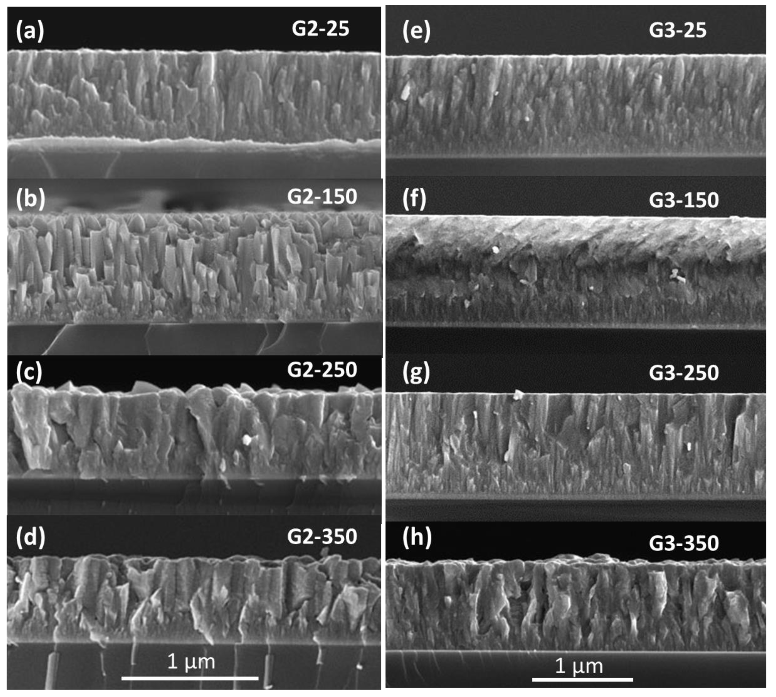
3.3. Film Microstructure

SEM cross-section images are shown in Figure 5a–d for the films in Group 1. In Figure 5a, deposited at 25 °C, the film shows a granular-powder-like morphology. Increasing the temperature to 150 °C, Figure 5b, shows a distinct columnar structure. It should be recalled (see Figure 2) that this film had a strong (111) texture, which may develop due to the increase in adatom mobility. Further increases to 250 °C and 350 °C show a coarse, faceted morphology with a voided columnar structure indicating low film density. The film thickness in these samples ranges from 2.4 to 2.9 µm.
Figure 6 shows SEM cross-sections of films from group 2 and 3. For film G2-25 (deposited at 25 °C), there is a discontinuous columnar structure and a relatively smooth surface. Increasing the temperature to 150 °C (Figure 6b) resulted in distinct angular crystallites, and highly faceted crystal tops, resulting in a rougher surface. Still higher temperatures of 250 °C (c) and 350 °C (d) revealed coarse grains, rough surfaces, and poor film density. Films deposited in group 3, which had an average of 50 at.% N and 12.3 at.% Ti, are shown in Figure 6e–h. At 25 °C, (G3-25) the structure is slightly more refined than the corresponding film from group 2. More significant differences are noted in comparing the films deposited at 250 °C and 350 °C. Here we observe that films in group 3 have more densely packed, finer crystallites, improved film density, and reduced surface roughness in comparison to group 2 films. At the highest temperature (G3-350), there is some coarsening of the structure, although not quite as extensive in sample G2-350. Since the bias levels for groups 2 and 3 were both −100 V, the general refinement of the grain structure can be attributed to higher Ti and N concentrations in group 3 films. Films from group 4 were also examined (not shown) and also exhibited dense columnar structures with highly smooth surfaces, although some coarsening and surface roughening was observed at the highest deposition temperature (350 °C). Overall, films with higher Ti/N levels had improved film density smoother surfaces, and avoided formation of coarse, faceted grains, while the increase in substrate bias (from −100 to −140 V) did not significantly alter grain structure. However, the effect of more energetic ion bombardment likely has an impact on other film characteristics, such as defect structure, dislocation density and film stress, effects which have been well-documented in the literature [31].

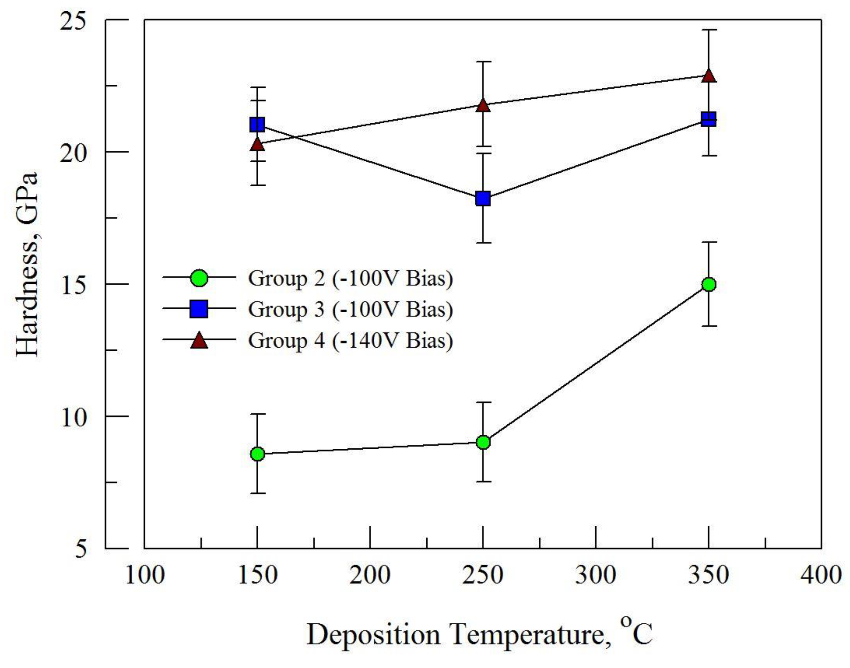
3.4. Mechanical Properties

An initial assessment of film hardness was made using Knoop micro-hardness testing. For films in group 1, results were similar to those obtained for films without Ti [28], with hardness levels in the range of 1000–1500 kg·f/mm2. However, the lower thickness for films in groups 2–4 required the use of nano-indentation, the results shown here focus on the films deposited in the 150–350 °C temperature range in groups 2–4. With nano-indentation, the appropriate load was selected so that the indentation depth did not exceed 10% of the film thickness. The results of the nano-indentation tests are shown in Figure 7. Films in Group 2 showed the lowest hardness, and also corresponds to the lowest (7.7 at.%) titanium and nitrogen (43.4 at.%) concentration for the three groups shown in the figure. For films in Groups 3 and 4 the hardness values ranged from 18 to 23 GPa. While the Ti concentration for these groups is similar (12.3 for Group 3 vs. 11.4 for Group 4), the higher bias in Group 4 samples (−140 V) provided higher hardness in the 250 °C and 350 °C samples. The hardness values obtained for these latter 2 groups are generally typical for transition metal nitrides [20,31] and are significantly higher than previously reported levels for nitrided stainless steels [3,10] and stainless steel-nitride thin films [21,28]. The reduced modulus values for these samples were in the range of 221–260 GPa.

4. Discussion

Films of nitrogen-incorporated stainless steel have been modified by the addition of titanium by co-sputtering, and the structure and mechanical properties of the films have been examined. For SS-N films with average Ti concentrations of 4.1 at.% (group 1 in Table 1), the concentration of N was similar to films deposited without Ti [26]. This level of nitrogen (33.8 at.%) is also close to that predicted by Christiansen and Somers [32] (38 at.%) for metastable equilibrium conditions in 304 and 316 stainless steels. The N concentration increased in group 2, which had an average of 7.7 at.% Ti with 43.4 at.%N. Further additions of Ti, to concentrations of 12.2 at.% (Group 3 average) or 11.4 at.% (Group 4 average) increased the N concentration to stoichiometric levels. These results can be considered in terms of the nitride-forming characteristics of the elements in stainless steel as well as titanium. Among these elements, TiN has the largest (negative) enthalpy of formation (ΔHf0 = −337.65 kJ/mol), with a somewhat smaller value for CrN (ΔHf0 = −117.15 kJ/mol), and significantly lower for Fe-nitrides (−3.74 kJ/mol for Fe2N and −10.4 kJ/mol for Fe4N) [33]. Therefore, the addition of Ti to stainless steel-nitride would be expected to increase nitrogen content. However, there appears to be a threshold in Ti content required to significantly increase the N concentration in the films (under the deposition conditions applied here), and the current experiments indicate this is between 8 at.% and 11 at.% Ti.
X-ray diffraction analysis of the higher-Ti films did not show any peak splitting or evidence of phase separation between Ti and the stainless steel constituents. This would suggest that the Ti atoms occupy random sites on the metal sublattice, although the close proximity of the TiN and SSN peaks in the higher-Ti samples (as shown in Figure 2 for groups 3 and 4) make a more detailed analysis difficult. Oddershede et al. [34] conducted EXAFS studies on nitrided AISI 316 stainless steel samples and concluded that the clustering of Cr atoms in the form of CrN, or even coherent CrN platelets were possible scenarios. Ti atoms would have an even stronger tendency for clustering due to the larger enthalpy of formation for TiN. However, additional studies are needed to determine if there is any evidence for such Ti-atom clustering on the metal sublattice.
TiN and CrN are commonly used and well-studied hard coating materials [31,35,36,37]. Fe-nitrides are less commonly used as hard coatings, although a limited number of studies have been conducted to examine their synthesis and mechanical properties [38,39,40]. Although films of nickel nitrides have been synthesized and studied [41,42], Ni has little affinity for nitrogen and as a poor nitride former, has limited commercial potential. While nitridation of stainless steels, primarily by plasma nitriding methods, has achieved a measure of commercial success, thin films of stainless steel-nitride have lower hardness than TiN or CrN [31,35] which limits potential applications. In this study, Ti additions have been shown to have a strong effect on film hardness levels, with significant increases observed at higher Ti levels. Hardness levels for stainless steel nitrides have been typically reported in the range of 10−15 GPa [2,3,4,9,10,24] although in thin films nitrides there is a strong dependence on deposition method and parameters used. In our recent study we found a Knoop hardness of 1275 kg/mm2 for S-phase-structured films deposited at 350 °C and a bias level of −140 V. Under similar conditions for the films in the present study, namely, sample G4-350, the hardness was 23.9 GPa (equivalent to 2200 kg/mm2 [43]), thereby representing nearly twice the hardness. For the N-stoichiometric films in groups 3 and 4 the hardness ranged from 18.2 to 22.9 GPa, which is in the typical hardness range for transition metal nitrides such as TiN and CrN.
The hardness of thin film nitrides can be related to intrinsic strength as well as microstructural characteristics. Comparison of films in Figure 5 and Figure 6 show that the Ti additions promote increased film density, a refined grain structure and reduced surface roughness. The coarse, faceted grains observed in films with low Ti contents (as well as films without Ti [28]) likely contribute to their lower hardness. This microstructural effect may also be due to their substoichiometric N concentrations, however, as lower N levels may also cause a reduction the intrinsic hardness. Supporting this latter hypothesis is the observation that the film in Figure 6h, G4-350, with 50.6 at.% N, showed as significantly coarser and open grain structure than G4-250, and yet had the highest hardness of all films tested. In addition to hardness, the reduced modulus values for these samples were determined and found to be in the range of 221–260 GPa. Additional studies on the fracture toughness and stress levels for these films using nano-indentation related methods [44,45] will help promote a better understanding of the competing factors of intrinsic strength vs. the effects of microstructure.
Based on the relative amounts of the stainless steel elements (Fe + Cr + Ni) vs. Ti under similar gun power levels (see Table 1, group 1), it is clear that the deposition rate of the stainless steel nitride is significantly higher than the rate of deposition from the Ti target, which could offer an economic advantage over TiN coatings. However, the stainless steel nitride coatings have inferior hardness and which implies poorer tribological properties. Modest additions of Ti to the stainless steel nitride are shown here to allow the coatings to reach full nitrogen stoichiometry and hardness levels competitive with TiN. In practice, the use of composite sputter targets may provide a way to obtain the desired film compositions and increased deposition rates compared to TiN alone.

5. Conclusions

Films of nitrogen-incorporated stainless steel have been modified by co-sputtering with titanium in a mixed Ar/N2 atmosphere. The following conclusions can be made from this study:
  • The effects Ti additions to stainless steel nitride films, up to a concentration of 12 at.% were examined and did not reveal the formation of any new, additional phases. All films had a nominally fcc-based structure with varying degrees of lattice distortion. Within this composition range, TiN appears to form a solid solution with stainless steel-nitride; however, the possibilities of Ti clustering on the metal sublattice or short-range ordering of N atoms cannot be discounted based on the observations made in this work.
  • The film structure was further evaluated by determination of the c/a ratio based on the (111)/(200) peak positions. Values of c/a > 1 were observed for most films, which can be associated with the formation of the S-phase. The effect of Ti was to increase the incorporation of N into the lattice, resulting in lower lattice distortion.
  • Films with higher titanium levels (generally >10 at.%) showed higher film densities, reduced surface roughness and a reduction in the coarse, faceted grain structure that is characteristic of stainless steel-nitride coatings.
  • The hardness of the films with higher Ti and N levels (group 3 and 4 in Table 1) was significantly higher than stainless steel nitride films or plasma-nitrided stainless steel surfaces previously reported in the literature. However, the effects of deposition parameters (temperature, bias) were less notable, as all films at the highest Ti compositions (groups 3 and 4) showed hardness levels between 18–23 GPa.

Author Contributions

F.I.A. performed the experiments, F.I.A. and J.E.K. analyzed the data and wrote the paper.

Funding

Partial funding for this project was provided by the Center of Manufacturing and Materials Innovation of the University of New Hampshire, Durham, NH, USA.

Acknowledgments

Faisal I. Alresheedi acknowledges support from Qassim University. The authors would also like to thank Bipasha Bose for her assistance with the nano-indentation measurements.

Conflicts of Interest

The authors declare no conflict of interest.

References

  1. Zhang, Z.L.; Bell, T. Structure and corrosion resistance of plasma nitrided stainless steels. Surf. Eng. 1985, 1, 131–136. [Google Scholar]
  2. Samandi, M.; Shedden, B.A.; Smith, D.I.; Collins, G.A.; Hutchings, R.; Tendys, J. Microstructure, corrosion, and tribological behaviour of plasma immersion ion-implanted austenitic stainless steel. Surf. Coat. Technol. 1993, 59, 261–266. [Google Scholar] [CrossRef]
  3. Menthe, E.; Rie, K.T.; Schultze, J.W.; Simson, S. Structure and properties of plasma-nitrided stainless steel. Surf. Coat. Technol. 1995, 412, 74–75. [Google Scholar] [CrossRef]
  4. Williamson, D.L.; Davis, J.A.; Wilber, P.J.; Vajo, J.J.; Wei, R.; Matossian, J.N. Relative roles of ion energy, ion flux, sample temperature in low-energy nitrogen ion implantation of Fe-Cr-Ni stainless steel. Nucl. Inst. Methods Phys. Res. B 1997, 127–128, 930–934. [Google Scholar] [CrossRef]
  5. Mändl, S.; Günzel, R.; Richter, E.; Möller, W. Nitriding of austenitic stainless steels using plasma immersion ion implantation. Surf. Coat. Technol. 1998, 372, 100–101. [Google Scholar] [CrossRef]
  6. Blawert, C.; Mordike, B.L. Nitrogen plasma immersion ion implantation for surface treatment and wear protection of austenitic stainless steel X6CrNiTi1810. Surf. Coat. Technol. 1999, 116–119, 352–360. [Google Scholar]
  7. Larisch, B.; Brusky, U.; Spies, H.-J. Plasma nitriding of stainless steels at low temperatures. Surf. Coat. Technol. 1999, 116–119, 205–211. [Google Scholar]
  8. Richter, E.; Günzel, R.; Parasacandola, S.; Telbizova, T.; Kruse, O.; Möller, W. Nitriding of stainless steel and aluminum alloys by plasma immersion ion implantation. Surf. Coat. Technol. 2000, 128–129, 21–27. [Google Scholar]
  9. Mändl, S.; Günzel, R.; Richter, E.; Möller, W.; Rauschenbach, B. Annealing behavior of nitrogen implanted stainless steel. Surf. Coat. Technol. 2000, 128–129, 423–428. [Google Scholar] [CrossRef]
  10. Singh, V.; Marchev, K.; Cooper, C.V.; Meletis, E.I. Intensified plasma-assisted nitriding of AISI 316L stainless steel. Surf. Coat. Technol. 2002, 160, 249. [Google Scholar] [CrossRef]
  11. Bratushka, S.N.; Tyurin, Y.N.; Kolisnichenko, O.V.; Mikhalev, A.D.; Tkachenko, R.Y.; Makhmudov, N.A.; Pshik, A.V.; Denisenko, R.; Yakushchenko, I.V. Structure and tribological characteristics of steel under melting by plasma flow and simultaneous Mo and W alloying. J. Frict. Wear 2012, 33, 22–33. [Google Scholar] [CrossRef]
  12. Pogrebnyak, A.D.; Bratushka, S.N.; Il’yashenko, M.V.; Makhmudov, N.A.; Kolisnichenko, O.V.; Tyurin, Y.N.; Uglov, V.V.; Pshik, A.V.; Kaverin, M.V. Tribological and physical-mechanical properties of protective coatings from Ni-Cr-B-Si-Fe/WC-Co-Cr before and after fission with a plasma jet. J. Frict. Wear 2011, 32, 84–90. [Google Scholar] [CrossRef]
  13. Marchev, K.; Hidalgo, R.; Landis, M.; Vallerio, R.; Cooper, C.V.; Giessen, B.C. The metastable m phase layer on ion-nitrided austenitic stainless steels Part 2: Crystal structure ad observation of its two-directional orientation anisotropy. Surf. Coat. Technol. 1999, 112, 67–70. [Google Scholar]
  14. Marchev, K.; Landis, M.; Vallerio, R.; Cooper, C.V.; Giessen, B.C. The m phase layer on ion-nitrided austenitic stainless steels III: An epitaxial relationship between the m Phase and the γ parent phase and a review of structural identification of this phase. Surf. Coat. Technol. 1999, 116–119, 184–188. [Google Scholar] [CrossRef]
  15. Fewell, M.P.; Mitchell, D.R.G.; Priest, J.M.; Short, K.T.; Collins, G.A. The nature of expanded austenite. Surf. Coat. Technol. 2000, 131, 300–306. [Google Scholar] [CrossRef]
  16. Fewell, M.P.; Priest, J.M. Higher-order diffractometry of expanded austenite using synchrotron radiation. Surf. Coat. Technol. 2008, 202, 1802. [Google Scholar] [CrossRef]
  17. Christiansen, T.; Somers, M.A.J. On the crystallographic structure of the S-phase. Scr. Mater. 2004, 50, 35–37. [Google Scholar] [CrossRef]
  18. Wu, D.; Kahn, H.; Dalton, J.C.; Michal, G.M.; Ernst, F.; Heuer, A.H. Orientation dependence of nitrogen supersaturation in austenitic stainless steel during low-temperature gas nitriding. Acta Mater. 2014, 79, 339–350. [Google Scholar] [CrossRef]
  19. Brink, B.K.; Stahl, K.; Christiansen, T.L.; Oddershede, J.; Winther, G.; Somers, M.A.J. On the elusive structure of expanded austenite. Scr. Mater. 2017, 131, 59–62. [Google Scholar] [CrossRef]
  20. Chou, W.J.; Yu, G.P.; Huang, J.H. Mechanical properties of TiN thin film coatings on 304 stainless steel substrates. Surf. Coat. Technol. 2002, 149, 7–13. [Google Scholar] [CrossRef]
  21. Saker, A.; Leroy, C.; Michel, H.; Frantz, C. Properties of sputtered stainless-steel coatings and structural analogy with low temperature plasma nitride layers of austenitic steels. Mater. Sci. Eng. 1991, A140, 702. [Google Scholar] [CrossRef]
  22. Bourjot, A.; Foos, M.; Frantz, C. Basic properties of sputtered 310 stainless steel-nitrogen coatings. Surf. Coat. Technol. 1990, 43–44, 533–542. [Google Scholar] [CrossRef]
  23. Shedden, B.A.; Kaul, F.N.; Samandi, M.; Window, B. The role of energetic neutrals in reactive magnetron sputtering of nitrogen-doped austenitic stainless steel coatings. Surf. Coat. Technol. 1997, 97, 102–108. [Google Scholar] [CrossRef]
  24. Terwagne, G.; Hody, H.; Colaux, J. Structural and quantitative analysis of stainless steel coatings deposited by DC-magnetron sputtering in a reactive atmosphere. Surf. Coat. Technol. 2002, 383, 174–175. [Google Scholar] [CrossRef]
  25. Kappaganthu, S.R.; Sun, Y. Formation of an MN-type cubic nitride phase in reactively sputtered stainless steel-nitrogen films. J. Cryst. Growth 2004, 267, 385–393. [Google Scholar] [CrossRef]
  26. Kappaganthu, S.R.; Sun, Y. Influence of sputter deposition conditions on phase evolution in nitrogen-doped stainless steel films. Surf. Coat. Technol. 2005, 59, 198. [Google Scholar] [CrossRef]
  27. Baranowska, J.; Fryska, S.; Suszko, T. The influence of temperature and nitrogen pressure on S-phase coatings deposited by reactive magnetron sputtering. Vacuum 2013, 90, 160. [Google Scholar] [CrossRef]
  28. Alresheedi, F.I.; Krzanowski, J.E. Structure and morphology of stainless steel coatings sputter-deposited in a nitrogen/argon atmosphere. Surf. Coat. Technol. 2017, 314, 105–112. [Google Scholar] [CrossRef]
  29. Benia, H.M.; Guemmaz, M.; Schmerber, G.; Mosser, A.; Parlebas, J.-C. Investigations on non-stoichiometric zirconium nitrides. Appl. Surf. Sci. 2002, 200, 231–238. [Google Scholar] [CrossRef]
  30. Yu, L.S.; Harper, J.M.; Cuomo, J.J.; Smith, D.A. Alignment of thin films by glancing angle ion bombardment during deposition. Appl. Phys. Lett. 1985, 47, 932–933. [Google Scholar]
  31. Mayrhofer, P.H.; Mitterer, C.; Hultman, L. Microstructural design of hard coatings. Prog. Mater. Sci. 2006, 51, 1032–1114. [Google Scholar] [CrossRef]
  32. Christiansen, T.; Somers, M.A.J. Controlled dissolution of colossal quantities of nitrogen in stainless steel. Metall. Mater. Trans. A 2006, 37A, 675–682. [Google Scholar] [CrossRef]
  33. Pankratz, L.B. Thermodynamic Properties of Carbides, Nitrides and Other Selected Substances; Bulletin 696; U.S. Dept. of the Interior: Albany, OR, USA, 1994.
  34. Oddershede, J.; Christiansen, T.L.; Stahl, K.; Somers, M.A.J. EXAFS investigation of low temperature nitride stainless steel. J. Mater. Sci. 2008, 43, 5358–5367. [Google Scholar] [CrossRef]
  35. Hones, P.; Sanjines, R.; Levy, F. Characterization of sputter-deposited chromium nitride thin films for hard coatings. Surf. Coat. Technol. 1997, 94–95, 398–402. [Google Scholar] [CrossRef]
  36. Cunha, L.; Andritschky, M.; Pischow, K.; Wang, Z. Microstructure of CrN coatings produced by PVD techniques. Thin Solid Films 1999, 355–356, 465–471. [Google Scholar] [CrossRef]
  37. Ernst, W.; Neidhardt, J.; Willmann, H.; Sartory, B.; Mayrhofer, P.H.; Mitterer, C. Thermal decomposition routes of CrN hard coatings synthesized by reactive arc evaporation and magnetron sputtering. Thin Solid Films 2008, 517, 568–574. [Google Scholar] [CrossRef]
  38. Tayal, A.; Gupta, M.; Gupta, A.; Ganesan, V.; Behera, L.; Singh, S.; Basu, S. Study of magnetic iron nitride thin films deposited by high power impulse magnetron sputtering. Surf. Coat. Technol. 2015, 275, 264–269. [Google Scholar] [CrossRef] [Green Version]
  39. Zhong, W.H.; Tay, B.K.; Lau, S.P.; Sun, X.W.; Li, S.; Sun, C.Q. Structural and magnetic properties of iron-nitride thin films deposited using a filtered cathodic vacuum arc. Thin Solid Films 2005, 478, 61–66. [Google Scholar] [CrossRef]
  40. Gupta, M.; Gupta, A.; Bhattacharya, P.; Misra, P.; Kukreja, L.M. Study of iron nitride thin films deposited by pulsed laser deposition. J Alloys Compd. 2001, 326, 265–269. [Google Scholar] [CrossRef]
  41. Dorman, G.J.W.R.; Sikkens, M. Structure of reactively sputtered nickel nitride films. Thin Solid Films 1983, 105, 251–258. [Google Scholar] [CrossRef]
  42. Popović, N.; Bogdanov, Ž.; Goncić, B.; Štrbac, S.; Rakočević, Z. Reactively sputtered Ni, Ni(N) and Ni3N films: Structural, electrical and magnetic properties. Appl. Surf. Sci. 2009, 255, 4027–4032. [Google Scholar] [CrossRef]
  43. Hay, J. Introduction to instrumented indentation testing. Exp. Tech. 2009, 33, 66–72. [Google Scholar] [CrossRef]
  44. Ghidelli, M.; Sebastiani, M.; Collet, C.; Guillemet, R. Determination of the elastic moduli and residual stresses of freestanding Au-TiW bilayer thin films by nanoindentation. Mater. Des. 2016, 106, 436–445. [Google Scholar] [CrossRef]
  45. Ghidelli, M.; Sebastiani, M.; Johanns, K.E.; Pharr, G.M. Effects of indenter angle on the micro-scale fracture toughness measurement by pillar splitting. J. Am. Ceram. Soc. 2017, 12, 5731–5738. [Google Scholar] [CrossRef]
Figure 1. Average compositions of the deposited films within each group based on the results shown in Table 1. The increase in Ti correlates with the increase in nitrogen, which is due to the strong gettering effect of Ti for N.
Coatings 09 00329 g001
Figure 2. XRD diffraction patterns of the films from groups 1–4. The solid vertical lines show the (111), (200) and (220) fcc-based reflections for the TiN structure, while the dashed lines show corresponding positions for the SSN structure with lattice constants based on the measured N levels and Equation (1).
Coatings 09 00329 g002
Figure 3. The calculated values of c/a based on Equation (2), using a111 and a200 values determined from the X-ray diffraction patterns, the c/a values decrease with increasing Ti (and N) concentrations, indicating a reduction in lattice distortion.
Coatings 09 00329 g003
Figure 4. (111) and (200) rocking curves for the films in Group 4, with ψ values ranging from −50° to +50°. Deposited films are: (a) G4-RT; (b) G4-150; (c) G4-250 and (d) G4-350.
Coatings 09 00329 g004
Figure 5. SEM cross-section images for films: (a) G1-25, (b) G1-150, (c) G1-250, and (d) G1-350. All images were taken in the secondary electron mode.
Coatings 09 00329 g005
Figure 6. SEM cross-section secondary electron images for films deposited from groups 2 and 3. Films shown in (ad) are from group 2, and show the development of coarse, faceted crystals with rough film surfaces. Films in (eh) show improved film density with smoother surfaces, although some coarsening and roughening is observed at 350 °C.
Coatings 09 00329 g006
Figure 7. Nano-indentation hardness for selected films. The standard deviation in the measured hardness values is shown. The higher hardness levels in groups 3 and 4 corresponds to higher nitrogen levels and improved film density.
Coatings 09 00329 g007
Table 1. Deposition parameters and film compositions for the SS-Ti-N films.
Temperature
°C
Iron
at.%
Chromium
at.%
Nickel
at.%
Oxygen
at.%
Nitrogen
at.%
Titanium
at.%
N/
(Fe + Ni + Cr + Ti)
Group 1: −100 V Bias, SS: 150 W, Ti: 150 W
2535.69.34.410.235.35.20.65
15040.38.94.412.530.43.50.53
25037.99.64.38.534.84.80.61
35042.011.55.03.734.83.00.57
Group 2: −100 V Bias, SS: 100 W, Ti: 100 W (*)
2527.78.36.14.845.28.00.90
25028.46.94.511.341.57.40.88
Group 3: −100 V Bias, SS: 50 W, Ti: 150 W
2523.76.95.22.750.311.21.07
15023.07.24.33.052.210.41.16
25022.46.25.94.546.514.60.95
35019.26.85.24.351.612.91.17
Group 4: −140 V Bias, SS: 50 W, Ti: 150 W
2523.06.25.14.350.311.11.11
15024.17.54.81.551.710.51.10
25021.86.44.63.252.911.11.20
35020.17.74.64.050.613.01.12
(*) Samples in group 2 were also deposited at 150 and 350 °C, but compositions were not analyzed.

