Article

Key Problems Affecting the Anti-Erosion Coating Performance of Aero-Engine Compressor: A Review

1
Science and Technology on Plasma Dynamics Laboratory, Air Force Engineering University, Xi’an 710038, China
2
State Key Laboratory for Manufacturing Systems Engineering, Xi’an Jiaotong University, Xi’an 710049, China
3
State Key Laboratory for Mechanical Behavior of Materials, Xi’an Jiaotong University, Xi’an 710049, China
4
China Aerodynamics Research and Development Center, Mianyang 621000, China
*
Authors to whom correspondence should be addressed.
Coatings 2019, 9(12), 821; https://doi.org/10.3390/coatings9120821
Submission received: 28 October 2019 / Revised: 29 November 2019 / Accepted: 29 November 2019 / Published: 3 December 2019
(This article belongs to the Special Issue Erosion of Nanostructured Coatings)

Abstract

:
Sand erosion has always been a key threat to the performance and service life of aero-engines. The compressor, the key component installed at the front of the aero-engine, suffers the most from sand erosion, especially compressors serving in deserts. Ceramic hard coating is a traditional way to improve the hardness and wear resistance of cutting and grinding tools. It may also be used to improve the erosion resistance of aero- engine compressor. However, the mechanism of erosion damage is complicated, which may include wear, secondary erosion, anisotropic erosion, impact, and fatigue. Recent research discovered the major problems with ceramic hard coating on aero-engine compressors. In this paper, these following problems are discussed: the design of coating material and structure, the preparation method and technology, the effects of droplets and clusters of coating surface, microstructure and characteristics of interface. The review of the major problems and possible solutions discussed in this paper may contribute to the future research on erosion coating theoretically and practically.

1. Introduction

Sand erosion is a common phenomenon in the industrial field [1,2,3], especially in area with both wind and sand such as power and energy equipment, resulting erosion on inner wall of the pipeline and so on. However, the erosion issue in the field of aviation is quite different and more severe than the above [4,5,6,7], such as helicopters and transports taking off and landing in desert areas, as sand particles are sucked into the engine at high speed, as shown in Figure 1. High concentration of sand leads to serious damage to high speed rotating compressor located at the front of the engine [8], which may further lead to downgrade of engine performance, decrease in reliability and even shorter the service life. Erosion has become a serious problem affecting the service in harsh environment of equipment, which needs to be solved urgently.
In order to solve the problem of sand erosion of aero-engine compressors and improve the performance of service in desert, many methods have been tested, such as the design of special particle separation devices for aero-engines [9], a change of engine compressor material [10], and so on. However, similar to the facemasks we wear in smog days, the separation device has limited ability to filter out fine particles, and it is very likely to cause an airflow problem. Changing the material will cause the engine to increase weight. At present, these methods can not solve the erosion problem completely and effectively.
Coating is an effective technology against erosion [11,12,13,14,15]. Coating with good strength and toughness on the surface of the material [16,17], combined with the use of a particle separation device, can negate the impact of the sand swallowed and promote service performance of the engine to the greatest extent. Though for many years, ceramic erosion-resistant coating has been used to improve the surface strength of materials in machinery industry, such as cutting and grinding tools [18,19,20,21], the aero-engine erosion is quite different from the conventional ones. There are still a number of problems that need to be studied.
First of all, the erosion in aero-engine is the combination of wear, secondary erosion, anisotropic erosion, impact, fatigue, and other damage modes [22,23,24]. The standards in strength and toughness of the coating are higher, and the protection of a single hard coating does not suffice. To address the high-speed erosion of the aero-engine compressor, the material system and structure of the ceramic coating should be redesigned.
At the same time, titanium alloy materials often used in aero-engine compressors are very sensitive to surface conditions [25], so it is very important to study the preparation methods and processes, which may have adverse effects on the properties of the substrate. At present, the key problems affecting erosion performance and damage assessment methods are still under study [26]. With the demanding requirements of aviation anti-erosion coatings and the continuous advancement of erosion/corrosion integration requirements, the application of coatings is still facing some challenges.
In this paper, the essence of sand erosion problem of aero-engine compressor is summarized, and the fundamentals affecting the erosion performance of protective coating are analyzed. High-speed cameras are used to observe the sand-break and secondary erosion phenomenon. Aiming at the special high strain rate erosion problem of compressor, the stress and strain fields of the coating under high strain rate impact are analyzed by finite element simulation, and the formation mechanism of annular crack is verified and explained by experiments. The advantages and disadvantages of different materials and structural system coatings are compared, and the preparation principle and process method of erosion resistant coatings for complex shape components are introduced. The effects on the erosion properties of the coatings of droplets, surface clusters, and interfaces formed during arc ion plating were analyzed by scanning electron microscope (SEM, TESCAN MIRA 3, TESCAN, Brno, Czech Republic) and transmission electron microscope (TEM, JEM-2100F, JEOL, Akishima, Japan), the anisotropic erosion and damage mechanism of the nanocomposite coatings were obtained based on the micro-nanomechanics. This paper is a summary of the research results of erosion coatings for many years, and some of the research results are of great significance to promote the theoretical and technological development of erosion resistant coatings.

2. Modes of Aero-Engine Compressor Erosion

The erosion damage of the aero-engine compressor includes wear, secondary erosion, anisotropic erosion, impact and fatigue, which are superimposed and coupled with each other. The complexity of the damage which is different from rather simple wear and tear on the surface of cutting or grinding tools urges us to take careful observation of the erosion in the aero-engine and have good understanding of the erosion characteristics which would guide the design of the coating structure, the selection of the fabrication process, and also the use of the performance evaluation method.

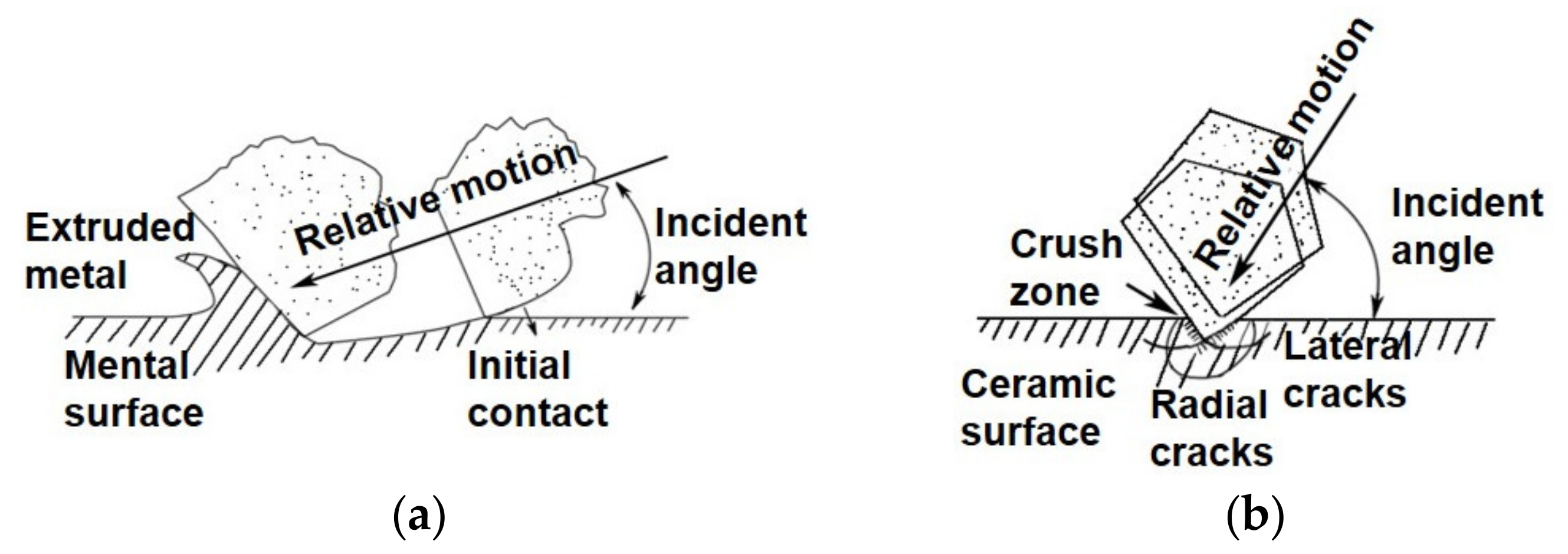
2.1. Wear and Secondary Erosion

In the service course of an engine, sand particles first interact with the high-speed rotating compressor surface. Because of the irregular shape of sand particles and the influence of air flow, the incident angle, defined as the angle between particle velocity vector and the material tangential surface, is randomly distributed ranging from 0° to 90° as shown in Figure 2. This incident angle is also being referred as erosion angle in this paper. The mechanism of erosion damage varies with the change of incident angle. It is roughly defined that the small angles are those less than 30°, at which wear mainly occurs, and large angles are those more than 30°. Generally speaking, for ductile materials, the most severe erosion damage take place at small angle with cutting being the main failure mode. For brittle materials, the most severe damage take place at large angles as layer spalling caused by elastic–plastic deformation and fatigue crack growth being the main failure mode [1,27,28,29,30,31]. Considering the bending shape and air flow characteristics of the engine compressor, the majority of sand erosion angles are generally not greater than 45°.
Secondary erosion is also a common phenomenon. The main composition of the sand particles is silicon dioxide, and natural sand is doped with various elements, such as Ca, Fe, Mg, and the like [33]. Sand particles may break upon impact of the initial erosion, and then the broken sand will erode the surface again. This phenomenon is called secondary erosion and it is observed throughout large and small erosion angles. As shown in Figure 3, we observe the crushing and secondary erosion of the sand through a high-speed camera, and the small size particles have done heavy erosion damage that cannot be ignored to the surface of the material. The pictures are taken with incident angles of 30°, 45°, 60°, and 90°, respectively. As seen from Figure 3 that sand particles are still intact at 30°; slightly broken at 45°; and completely broken at 90°. It is concluded that sand grains are more severely broken with the increase of erosion angle.
Experimental results of Finnie’s paper [34,35] revealed that ductile materials like metals and brittle materials such as ceramics exhibit different erosion patterns with the change of erosion angle during erosion. The erosion rate of ductile materials has a peak value at small erosion angle, and goes down as the angle increases; while the erosion rate of brittle materials goes up with the increase of erosion angle reaching maximum at 90°.

2.2. High Strain Rate Impact

The blade of aero-engine compressor is in a state of high speed rotation. The collision velocity between sand particles and blade is calculated to be exceeding the speed of sound (340 m/s), and the velocity of blade tip can reach as high as 400–500 m/s. The strain rate caused by high speed impact is very high. Compared to quasi-static mechanical condition (strain rate 10−4/s–10−1/s), the response characteristics and mechanical behavior of both substrate and coating under dynamic mechanical conditions (strain rate 102/s–104/s) are significantly different. The mechanical strengthening of nano-multilayer coatings is essentially resulted by the hindrance of high density interface to dislocation movement in nano-thickness single-layer [36,37,38]. Under high strain rate loading, the viscous damping effect of nano-multilayer interface on dislocation becomes the key factor affecting the dynamic properties and mechanical behavior of multilayer coatings. Since little attention has been paid to the difference between conditions, existing research methods on the damage problem are limited, so does the understanding of performance at high strain rate.
As shown in Figure 4, a tensile stress ring is generated on the surface of the coating when it is impacted by particles. The coating surface is deformed during the process. As the particle moves downward, the tensile stress peaks on the surface of the coating propagate outward along the radius [7,11,39,40,41]. These tensile peaks can easily lead to circular cracks due to the poor tensile strength of ceramic coatings. These circular cracks and radial cracks at the interface are likely to be connected, which can lead to the coating being peeled off. This coalescing is the main cause of coating failure [7,42].

2.3. Anisotropy of Coating

The mechanical properties and the deformation of the coating are closely related to direction and amplitude of the load. The irregular moving sand particles have strong randomness in all direction, but the direction of the coating is evidently parallel to the substrate surface. As shown in Figure 5, the anisotropy of coating resulted in an obvious difference of the impact to coating between different load directions. We also carried out the micro-nano mechanical property test of the coating at different angles, specifically 0° and 90° with quasi static loading. Meanwhile, the impact damage behavior after single sand particle impacting with high strain rate was also studied.

2.4. Impact Fatigue of Coatings

Unlike high stress material failures such as yield or fracture, fatigue occurs when the material is subject to low stress level. As the result of repeated load of sand and dust particles, this impact fatigue is the main damage mode of coating erosion [22,43,44]. The fatigue behavior of the aero-engine blade is very complex. In order to obtain some insight, we conducted experiments on a variety of load arrangements, namely high frequency with low stress, low frequency with high stress, and compound load.
Before the test, some approximations have to be made. In real circumstances, the impact velocity of sand particles is hard to accurately control; the influence of irregular shapes and rotation along the course of movement are also complex to analyze. Therefore, a simplified model is built as shown in Figure 6, in which all the sands are considered to be hard spherical particles with identical velocity [45].
The damage morphologies of physical vapor deposition (PVD)-made TiN/Ti binary coatings with different thickness under 104 repeated impacts of hard Si3N4 pellets are shown in Figure 7. Circumferential cracks appear at the edges of impact pits of all coatings. Coatings exfoliation occurs at the center (O), middle (M) and edge (C). The pits formed in depth of the coating are not caused by the peeling off. The two-dimensional contour lines are circular arc-shaped. There are materials extruded at the edge of the impact pits. Therefore, it can be concluded that the pits are deformations caused by repeated impact in a vertical direction by sand particles. It is also notable that there are three main characteristics of repeated impact fatigue: circumferential crack, spalling, and coating/matrix deformation, among which spalling is the most important one.

3. Integration of Coating Preparation Equipment and Coating Process

3.1. Design of Anti-Erosion Coating Material and Structure

In the past two decades, the surface engineering technology has developed rapidly. Hard coating has been widely used in grinding tool surface to improve strength, service performance and even life [46,47,48,49]. Ceramic hard coating is the first choice when it comes to anti-erosion coating [50,51]. However, as we discussed above, erosion in aero-engine is very different from the conventional wear. Therefore, compared to the ceramic coating on the surface of the cutting and grinding tools, the toughness and strength demands of coating have been raised to adapt to the wear, impact, fatigue and other modes of the erosion damage. The performance of single traditional ceramic coating such as TiN, CrN simply can not meet the requirements and needs to be optimized.
Meanwhile, the structure of the coating can be complex. Single-layer, multilayer, and nano-multilayer are three typical types, as shown in Figure 8. Specifically for nano-multilayer, the thickness of a single layer coating is less than 100 nm. The soft and hard alternating structure and high-density interface of the nano-multilayer coatings are widely considered to be advantages of improving the strength and toughness for its ability to block dislocation movement and inhibit crack growth [52,53]. It is a hot spot for international research in recent years.

3.2. Preparation Method and Process of Anti-Erosion Coating PVD

Thermal spraying, cold spraying, physical vapor deposition and chemical vapor deposition (CVD) are the main methods of coating technology. However, for engine compressor, considering the thickness, roughness, bonding strength, and preparation temperature, coatings prepared by thermal spray and cold spray are difficult to control on the order of microns; chemical vapor deposition has some corrosion and high temperature issues. Thus, PVD has become the mainstream technology used in the preparation of erosion resistant coatings both domestic and international. PVD also include many specific coating preparation methods, such as magnetron sputtering and arc ion plating [54,55,56]. Arc ion plating (AIP), as a common method for non-high precision coatings, performs exceptionally well in preparing resistance coatings because of its high bonding strength, high deposition efficiency and low cost [57,58]. There are also many important technological processes for the preparation of coatings, like pre-treatment, coating deposition, and post-treatment. Take pre-treatment as an example; sand blowing is essential for cleaning up the surface and improving roughness [59]. The bonding strength of coating would be inferior if the surface layer of the material is contaminated. Thus, the selection of methods and parameters is critical in the preparation process.
The principle of AIP is shown in Figure 9. The vaporizer discharges the gas between a trigger and the target material forming high current arc in a low-pressure chamber [60,61]. The arc which generates vaporized ion-rich plasma of target material is constrained in a designated area by a magnetic field [62]. The ions are accelerated in the electric field and deposited onto the substrate forming the desired coating.

3.3. Erosion Resistant Coating for Complex Aeronautical Components

AIP has some characteristics such as low operation temperature, non-corrosive, high strength, thickness-controllable and so on [63,64]. However, from the application perspective of anti-erosion coating in aero-engines, there are still many problems yet to be solved. For instance, AIP is a line-of-sight processing technology. That is to say, it is only feasible to deposit coating along the direction of the plasma beam. Although the deposition can be accelerated by applying negative biased voltage on the substrate, the anisotropic effect is still notable.
Nowadays, in aeronautical components, most vane disks have non-detachable structure. The distortion and mutual occlusion between the blades are very serious. It is necessary to determine the injection mode and design the angle of plasma beam according to the shape and structure of the sample. It is also important to consider the deposition efficiency and internal stress control of the coating.
As shown in Figure 10, the blisk is fixed on a shaft which rotates at a low speed. Two arc sources are arranged in the direction facing the blades where erosion occurs the most, and one arc source is arranged in the opposite direction. This arrangement can effectively improve deposition rate of the coating. The problem of uneven deposition on complex shape samples can be effectively solved by arranging the arc sources and the shaft in this way [65].

4. Surface and Interface Problems of the Coating

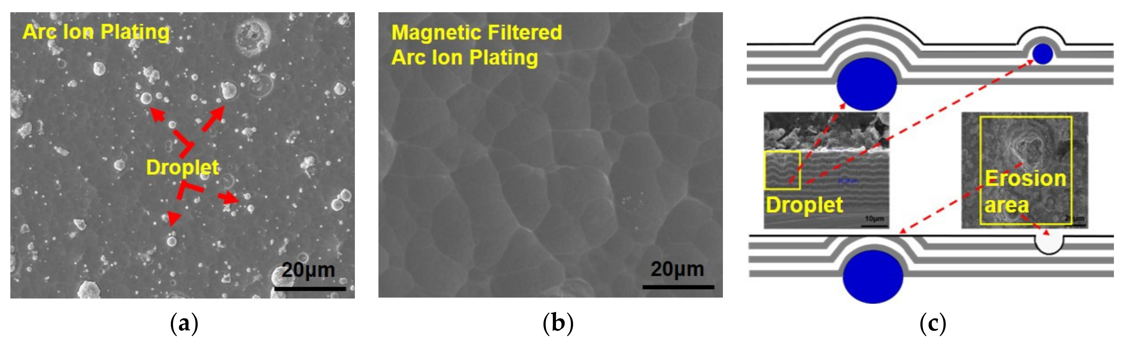
4.1. Effect of Arc Ion Plating Droplets on Erosion Performance

During arc ion plating, due to the large local current, the surface temperature of the target material exceeded 1000°, which led to charged droplets of metal to form instead of pure plasma. The droplets splashed directly onto the surface of the substrate, forming surface defects and increasing roughness (as shown in Figure 11a). Experiment result shows that roughness of coating has immense impact on the erosion rate of the coating [66,67]. These protrusions formed by droplets are susceptible to sand erosion, and micro pits would form after the chunks are being scraped off. The pits are very easy to become concentration sites of fatigue or corrosion, resulting in the coating being washed away quickly (as shown in Figure 11c). Droplets can be removed by magnetic filtration [68,69], and the surface quality of the coating can be improved (as shown in Figure 11b). However, the downside is that the deposition rate would be negatively affected.

4.2. Effect of Columnar Boundary on Erosion Performance

A cluster is a kind of microstructure on surface of coating prepared by arc ion plating. This phenomenon is rarely mentioned in the literature before. A cluster is formed of columnar crystals creating a small bulge with clear profile. Aside from droplets, cluster of surface coating is a key factor affecting the erosion rate, as erosion begins with the grinding of the relative protruding part of the surface by sand particles. In order to establish the quantitative relationship between the process parameters, cluster microstructure and erosion macroscopic properties, we defined a new variable called cluster density, which stands for the number of clusters in a unit area, shown in formula (1).
D = N S
where D is the value of cluster density, which is the ratio of the number of cluster in the statistics area; N is the number of cluster in statistics area; and S is the measure of statistics area.
The influence of process parameters on the cluster density, and the influence of profile columnar crystals seen by SEM electron microscope on cluster density and the influence of clusters on erosion performance are shown in Figure 12.

4.3. Interface Problem

Interface science is an interdisciplinary branch of learning, involving mechanical, physical, material, and so on, which is being paid more and more attention in recent years. Research on interface science is essential and very important to coating technology [52,53,70,71]. Erosion resistant coatings are generally parallel to the surface of the material. In order to improve the bonding strength between the coating and the substrate, a transition layer is generally adopted. For instance, if the substrate is Ti alloy and the coating is TiN, Ti will generally be used as the material for the transition layer [7,24,72]. Interfaces of all kinds, such as those between coating and substrate, between different layers of the coating, and even inside the coating itself have great influence on the overall properties of the coating. The roughness of the interface also has a great influence on the bonding strength. We conducted experiments on the effect of interface on the bonding strength and the erosion performance of the coating. The results showed that the bonding strength differed more than twice in magnitude.
Figure 13a shows the microstructure of TiN/ZrN nano-multilayer coatings with nanoscale layers periodically fabricated by PVD technology. The individual layer thicknesses of the TiN and ZrN were 140 and 100 nm, respectively, which were small enough to achieve nano-grained structures within each layer. As Figure 13b presents, the grains in both layers were columnar structured, and the grain sizes were approximately the same to the thickness of each layer. This also implies that a typical way to obtain the smaller grain structure is to reduce the thickness of single layer. The interfaces are very dense, without presence of micro/nano-scale porosities or other phases [73,74,75,76,77].
In order to better understand the effect of cracks in the coating, the cross-sectional erosion area of the coating was observed by SEM. Showing in Figure 14a,b, when the crack propagates in the multilayer coating, the crack can be branched (zone A) and deflected (zone B). Crack tips inside the layer acted as stress concentrators that weakened the bonding strength. The multilayer coating exhibited better resistance against crack extension as the researches discussed [78,79].

5. Anisotropy and Damage Mechanism of Coating

5.1. Anisotropy and Damage Mechanism by Nanoindentation

The thickness of these films is limited to the order of micro-meters due to fabrication method and therefore the mechanical testing is restricted to small-scale techniques. The experiment utilized nanoindentation and pillar compression; both are becoming the increasingly popular techniques in microscale mechanical testing [42,80,81,82,83,84,85]. However, these studies are limited to the loading direction only perpendicular to the layer direction. Little work has been done to study the performance differences of coatings under different loading directions.
Recent anisotropic deformation and fracture mechanisms studies by Yang and He explored that by a combination of nano-indentation and micropillar compression techniques, TiN/ZrN nano-multilayer coatings behaves differently on different loading orientations [86]. Their research showed that compared with the 90° loading direction, the coating with 0° loading direction has a stiffer and stronger performance. Examined by the detailed TEM characterization after nanoindentation, the results suggested that the coatings were bended and kinked in the 0° direction, as kinking bands appeared. At 90°, the main mechanisms were the plastic deformation of ZrN layer and the interface Mode I cracking between TiN and ZrN layers. Also revealed by the micropillar compression technique, the results evidenced that the layers were more brittle at the 0° direction than the 90° direction. The SEM test after micropillar compression showed that cracking propagation and termination induced by the interface were beneficial for the toughness property of the TiN/ZrN nano-multilayer coatings.

5.2. Anisotropy and Damage Mechanism by Single Sand Erosion

Combined with the service condition of aero-engines in the desert, in order to understand the mechanism of sand erosion of coating more clearly, we use single particle sand to study the erosion of TiN/ZrN nano-multilayer coatings. For sand erosion test, the damage morphology and response of samples are often the focus of attention. However, it has been shown that the impact response of sand particles can also affect the erosion performance of materials. About 20%–30% of the energy from the eroded sand is transferred to the rebounded sand [87]. The erosion protection ability of the coating can be qualitatively reflected by recording the incident and rebounded informations and fragmentation of the sand through the erosion test of single particle sand, which can effectively supplement the erosion test.
The tests of single sand impacting on TiN/ZrN nano-multilayer coatings at following angles: 30°, 45°, 60°, and 90° with 130 m/s were carried by WSS-1 air gun system, and the results were observed with a high-speed camera. Figure 15 shows the results of single sand impacting TiN/ZrN nano-multilayer coatings at 130 m/s. The number of broken sand particles is less at 30° and 45° erosion angle than at 60° and 90° erosion angles, At 60° and 90° erosion angles, the sand is seriously broken and becoming powder-like, which proves that the second erosion plays an important role in the actual sand erosion. At the same time, there is a serious law of fragmentation with the increase of erosion attack angle.
In the process of sand erosion, the main part of the incident kinetic energy is transformed into the fracture energy, the rebound kinetic energy, and the rotational kinetic energy of the sand particles besides the energy exhausted by collision damage to the sample. Among which the rotational kinetic energy carried by particle rotation is rather low and can be neglected. Therefore, the energy conversion behavior during this process can be directly reflected by the statistics of the degree of sand fragmentation.
Some research results showed that the impact velocity and angle of the sand particles [88], the toughness of the target coating and the ratio of its hardness to the sand particles [89,90] all have an impact on the erosion rate of the coating. Additional, researches showed that for the erosion test, the erosion rate decreases with the increase of the number of broken particles [89]. Combined with the impact rebound test of single sand particles, the relationship between the mechanical properties of coating and the status of sand fracture can be established, which will help to predict the erosion resistance of the coating.

6. Conclusions

After many years of research on erosion-resistant coatings, we have come to the following conclusions:
  • The erosion problem of aero-engine compressors is very complicated, which is very different from the traditional erosion wear problems, including wear, secondary erosion, high strain rate impact, anisotropy, fatigue, and other issues. The study of the erosion-resistant coating of the compressor should be analyzed in combination with the characteristics of the service environment.
  • The performance of the coating material system and structure directly determines the performance of the coating. Many basic research results show that the nano-multilayer coatings have good mechanical properties and erosion resistance, but the coating properties should be considered by combining the material system structure, preparation method, and process. Especially for the components with complex shape, the preparation of the nano-multilayer coatings is still very difficult. It is also very important to improve the stability of the process and reduce the cost.
  • The presence of droplets easily forms defects, changes the roughness of the surface, forms a fatigue source, and preferentially fills the erosion zone. Cluster density is the most important factor affecting erosion resistance. The presence of the interface can hinder dislocation motion and limit crack propagation. Proper use of process conditions to optimize these problems can greatly improve the erosion resistance of the coating.
  • The anisotropy of erosion resistant coating is different from that of hard ceramic coating used in cutting tools and grinding tools. Although most of the coatings are parallel to the substrate surface, the anisotropy of erosion coating is inevitable, but the anisotropy of erosion coating is more obvious because of the randomness of erosion direction of sand particles, which has a great influence on the properties and life of the coating. In this paper, the anisotropy of the coating is characterized by micro-nanomechanics, and the mechanical properties of the coating are obtained. However, as we know, the micro-nanomechanics test is still quasi-static. We are also trying to use nano-impact and other methods, and combined with erosion experiments to further reveal the mechanical properties and anisotropy of the coating at a high strain rate.

Author Contributions

Conceptualization, X.H.; methodology, J.C.; software, Z.Z.; validation, Z.F.; resources, L.Y.; data curation, Z.Y.; writing—original draft preparation, D.S.; writing—review and editing, G.H.

Funding

This research was funded by National Science and Technology Major Project (2017-VII-0012-0107).

Acknowledgments

The authors would like to acknowledge Xi’an Jiaotong University and the Guangdong Institute of New Materials for their support and assistance.

Conflicts of Interest

The authors declare that they have no conflict of interest.

References

  1. Haugen, K.; Kvernvold, O.; Ronold, A.; Sandberg, R. Sand erosion of wear-resistant materials: Erosion in choke valves. Wear 1995, 186, 179–188. [Google Scholar] [CrossRef]
  2. Wong, C.Y.; Solnordal, C.; Swallow, A.; Wang, S.; Graham, L.; Wu, J. Predicting the material loss around a hole due to sand erosion. Wear 2012, 276, 1–15. [Google Scholar] [CrossRef]
  3. Hussain, E.; Robinson, M. Erosion–corrosion of 2205 duplex stainless steel in flowing seawater containing sand particles. Corros. Sci. 2007, 49, 1737–1754. [Google Scholar] [CrossRef]
  4. Pepi, M.; Squillacioti, R.; Pfledderer, L.; Phelps, A. Solid particle erosion testing of helicopter rotor blade materials. J. Fail. Anal. Prev. 2012, 12, 96–108. [Google Scholar] [CrossRef]
  5. van der Walt, J.P.; Nurick, A. Erosion of dust-filtered helicopter turbine engines part I: Basic theoretical considerations. J. Aircr. 1995, 32, 106–111. [Google Scholar] [CrossRef]
  6. Bousser, E.; Martinu, L.; Klemberg-Sapieha, J.E. Solid particle erosion mechanisms of hard protective coatings. Surf. Coat. Technol. 2013, 235, 383–393. [Google Scholar] [CrossRef]
  7. Zhang, H.; Li, Z.; He, W.; Liao, B.; He, G.; Cao, X.; Li, Y. Damage evolution and mechanism of TiN/Ti multilayer coatings in sand erosion condition. Surf. Coat. Technol. 2018, 353, 210–220. [Google Scholar] [CrossRef]
  8. Yaer, X.; Shimizu, K.; Qu, J.; Wen, B.; Cao, X.; Kusumoto, K. Surface deformation micromechanics of erosion damage at different angles and velocities for aero-engine hot-end components. Wear 2019, 426, 527–538. [Google Scholar] [CrossRef]
  9. Monhardt, R.J.; Kudlacik, L.; Nikkanen, J.P.; Niiler, J. Combined Surge Bleed and Dust Removal System for a Fan-Jet Engine. US Patent GB2111601B, 28 November 1984. [Google Scholar]
  10. Mannava, S.; McDaniel, A.E.; Cowie, W.D.; Halila, H.; Rhoda, J.E.; Gutknecht, J.E. Laser Shock Peened Gas Turbine Engine Fan Blade Edges. U.S. Patent 5,591,009, 7 January 1997. [Google Scholar]
  11. Bielawski, M.; Beres, W. FE modelling of surface stresses in erosion-resistant coatings under single particle impact. Wear 2007, 262, 167–175. [Google Scholar] [CrossRef]
  12. Guo, L.; Chen, G. High-quality diamond film deposition on a titanium substrate using the hot-filament chemical vapor deposition method. Diam. Relat. Mater. 2007, 16, 1530–1540. [Google Scholar] [CrossRef]
  13. Li, Y.; Zhang, C.; Ma, H.; Yang, L.; Zhang, L.; Tang, Y.; Li, X.; He, L.; Feng, R.; Yang, Q.; et al. CVD nanocrystalline diamond coatings on Ti alloy: A synchrotron-assisted interfacial investigation. Mater. Chem. Phys. 2012, 134, 145–152. [Google Scholar] [CrossRef]
  14. Di, J.; Wang, S.; Zhang, L.; Cai, L.; Xie, Y. Study on the erosion characteristics of boride coatings by finite element analysis. Surf. Coat. Technol. 2018, 333, 115–124. [Google Scholar] [CrossRef]
  15. Chen, J.; Geng, M.; Li, Y.; Yang, Z.; Chai, Y.; He, G. Erosion resistance and damage mechanism of TiN/ZrN nanoscale multilayer coating. Coatings 2019, 9, 64. [Google Scholar] [CrossRef] [Green Version]
  16. Zhang, H.; Li, Z.; Ma, C.; He, W.; Cao, X.; Li, Y. The anti-sand erosion performance of TiN films fabricated by filtered cathodic vacuum arc technique at different nitrogen flow rates. Ceram. Int. 2019, 45, 10819–10825. [Google Scholar] [CrossRef]
  17. Kim, Y.S.; Park, H.J.; Mun, S.C.; Jumaev, E.; Hong, S.H.; Song, G.; Kim, J.T.; Park, Y.K.; Kim, K.S.; Jeong, S.I.; et al. Investigation of structure and mechanical properties of TiZrHfNiCuCo high entropy alloy thin films synthesized by magnetron sputtering. J. Alloy. Compd. 2019, 797, 834–841. [Google Scholar] [CrossRef]
  18. Zhang, S.; Zhu, W. TiN coating of tool steels: A review. J. Mater. Process. Technol. 1993, 39, 165–177. [Google Scholar] [CrossRef]
  19. Liu, W.; Li, A.; Wu, H.; He, R.; Huang, J.; Long, Y.; Deng, X.; Wang, Q.; Wang, C.; Wu, S. Effects of bias voltage on microstructure, mechanical properties, and wear mechanism of novel quaternary (Ti, Al, Zr) N coating on the surface of silicon nitride ceramic cutting tool. Ceram. Int. 2016, 42, 17693–17697. [Google Scholar] [CrossRef]
  20. Baronins, J.; Antonov, M.; Bereznev, S.; Raadik, T.; Hussainova, I. Raman spectroscopy for reliability assessment of multilayered AlCrN coating in tribo-corrosive conditions. Coatings 2018, 8, 229. [Google Scholar] [CrossRef] [Green Version]
  21. Cai, F.; Gao, Y.; Zhang, S.; Zhang, L.; Wang, Q. Gradient architecture of Si containing layer and improved cutting performance of AlCrSiN coated tools. Wear 2019, 424, 193–202. [Google Scholar] [CrossRef]
  22. Bousser, E.; Martinu, L.; Klemberg-Sapieha, J. Solid particle erosion mechanisms of protective coatings for aerospace applications. Surf. Coat. Technol. 2014, 257, 165–181. [Google Scholar] [CrossRef] [Green Version]
  23. Zhang, D.; Cabrera, E.; Zhao, Y.; Zhao, Z.; Castro, J.M.; Lee, L.J. Improved sand erosion resistance and mechanical properties of multifunctional carbon nanofiber nanopaper-enhanced fiber reinforced epoxy composites. Adv. Polym. Technol. 2018, 37, 1878–1885. [Google Scholar] [CrossRef]
  24. Cao, X.; He, W.; Liao, B.; Zhou, H.; Zhang, H.; Tan, C.; Yang, Z. Sand particle erosion resistance of the multilayer gradient TiN/Ti coatings on Ti6Al4V alloy. Surf. Coat. Technol. 2019, 365, 214–221. [Google Scholar] [CrossRef]
  25. Geng, M.; He, G.; Sun, Z.; Chen, J.; Yang, Z.; Li, Y. Corrosion damage mechanism of TiN/ZrN nanoscale multilayer anti-erosion coating. Coatings 2018, 8, 400. [Google Scholar] [CrossRef] [Green Version]
  26. Shinde, S.M.; Kawadekar, D.M.; Patil, P.A.; Bhojwani, V.K. Analysis of micro and nano particle erosion by analytical, numerical and experimental methods: A review. J. Mech. Sci. Technol. 2019, 33, 2319–2329. [Google Scholar] [CrossRef]
  27. Wentzel, E.J.; Allen, C. Erosion-corrosion resistance of tungsten carbide hard metals with different binder compositions. Wear 1995, 181, 63–69. [Google Scholar] [CrossRef]
  28. Wood, R. The sand erosion performance of coatings. Mater. Des. 1999, 20, 179–191. [Google Scholar] [CrossRef]
  29. Wheeler, D.; Wood, R. Solid particle erosion of diamond coatings under non-normal impact angles. Wear 2001, 250, 795–801. [Google Scholar] [CrossRef]
  30. Yang, Q.; McKellar, R. Nanolayered CrAlTiN and multilayered CrAlTiN–AlTiN coatings for solid particle erosion protection. Tribol. Int. 2015, 83, 12–20. [Google Scholar] [CrossRef]
  31. Geng, M.R.; Chen, J.; Yang, Z.F.; Liu, M.J.; He, G.Y.; Wang, X.D. Dependent effects of particle size on erosion wear mechanism of TC4 titanium alloy. China Surf. Eng. 2018, 31, 17–26. (In Chinese) [Google Scholar]
  32. Finnie, I. Erosion of surfaces by solid particles. Wear 1960, 3, 87–103. [Google Scholar] [CrossRef]
  33. Dickinson, W.R.; Suczek, C.A. Plate tectonics and sandstone compositions. Aapg Bull. 1979, 63, 2164–2182. [Google Scholar]
  34. Finnie, I. Some reflections on the past and future of erosion. Wear 1995, 186, 1–10. [Google Scholar] [CrossRef]
  35. Sheldon, G.; Finnie, I. On the ductile behavior of nominally brittle materials during erosive cutting. J. Eng. Ind. 1966, 88, 387–392. [Google Scholar] [CrossRef]
  36. Mayer, C.; Yang, L.; Singh, S.; Xie, H.; Shen, Y.-L.; Llorca, J.; Molina-Aldareguia, J.; Chawla, N. Orientation dependence of indentation behavior in Al–SiC nanolaminate composites. Mater. Lett. 2016, 168, 129–133. [Google Scholar] [CrossRef] [Green Version]
  37. Yang, L.; Mayer, C.; Chawla, N.; Llorca, J.; Molina-Aldareguía, J. Deformation mechanisms of ultra-thin Al layers in Al/SiC nanolaminates as a function of thickness and temperature. Philos. Mag. 2016, 96, 3336–3355. [Google Scholar] [CrossRef]
  38. Han, S.; Yang, L.; Liu, H.; Sun, X.; Jiang, R.; Mao, W.; Chen, Z. Micro-mechanical properties and interfacial engineering of SiC fiber reinforced sol-gel fabricated mullite matrix composites. Mater. Des. 2017, 131, 265–272. [Google Scholar] [CrossRef]
  39. Immarigeon, J.-P.; Chow, D.; Parameswaran, V.; Au, P.; Saari, H.; Koul, A.K. Erosion testing of coatings for aero engine compressor components. Adv. Perform. Mater. 1997, 4, 371–388. [Google Scholar] [CrossRef]
  40. Stodola, J. Modelling of ball impacts on coatings and erosion of special technique components. Adv. Mil. Technol. 2011, 6, 1802–2308. [Google Scholar]
  41. Hassani, S.; Bielawski, M.; Beres, W.; Balazinski, M.; Martinu, L.; Klemberg-Sapieha, J. Impact stress absorption and load spreading in multi-layered erosion-resistant coatings. Wear 2010, 268, 770–776. [Google Scholar] [CrossRef]
  42. Chawla, N.; Singh, D.; Shen, Y.-L.; Tang, G.; Chawla, K. Indentation mechanics and fracture behavior of metal/ceramic nanolaminate composites. J. Mater. Sci. 2008, 43, 4383–4390. [Google Scholar] [CrossRef]
  43. He, G.; Li, Y.; Chai, Y.; Zhang, Y.; Wang, G. Review of key issues on coating against sand erosion of aero-engine compressor blade. Acta Aeronaut. Astronaut. Sin. 2015, 36, 1733–1743. [Google Scholar]
  44. Cao, X.; He, W.F.; He, G.; Liao, B.; Zhang, H.; Li, Y. Effects of DLC and TiN coatings on sand erosion resistance of TC4 titanium alloy. China Surf. Eng. 2016, 29, 60–67. (In Chinese) [Google Scholar]
  45. Xu, W.; He, G.; Cai, Z.; Liao, B.; Cao, X.; He, W. Damage analysis of TiN/Ti coatings under cycling impact with hard particles. China Surf. Eng. 2017, 30, 28–35. (In Chinese) [Google Scholar]
  46. Hogmark, S.; Jacobson, S.; Larsson, M. Design and evaluation of tribological coatings. Wear 2000, 246, 20–33. [Google Scholar] [CrossRef]
  47. Rausch, S.; Biermann, D. Grinding of hard-material-coated forming tools on machining centers. Procedia CIRP 2012, 1, 388–392. [Google Scholar] [CrossRef] [Green Version]
  48. Beake, B.; Ning, L.; Gey, C.; Veldhuis, S.; Komarov, A.; Weaver, A.; Khanna, M.; Fox-Rabinovich, G. Wear performance of different PVD coatings during hard wet end milling of H13 tool steel. Surf. Coat. Technol. 2015, 279, 118–125. [Google Scholar] [CrossRef]
  49. Sharma, V.; Pandey, P.M. Recent advances in turning with textured cutting tools: a review. J. Clean. Prod. 2016, 137, 701–715. [Google Scholar] [CrossRef]
  50. Deng, J.; Wu, F.; Lian, Y.; Xing, Y.; Li, S. Erosion wear of CrN, TiN, CrAlN, and TiAlN PVD nitride coatings. Int. J. Refract. Met. Hard Mater. 2012, 35, 10–16. [Google Scholar] [CrossRef]
  51. Lin, S.; Zhou, K.; Dai, M.; Lan, E.; Shi, Q.; Hu, F.; Kuang, T.; Zhuang, C. Structural, mechanical, and sand erosion properties of TiN/Zr/ZrN multilayer coatings. Vacuum 2015, 122, 179–186. [Google Scholar] [CrossRef]
  52. Li, G.; Yang, G. Understanding of degradation-resistant behavior of nanostructured thermal barrier coatings with bimodal structure. J. Mater. Sci. Technol. 2019, 35, 231–238. [Google Scholar] [CrossRef]
  53. Li, G.-R.; Wang, L.-S. Durable TBCs with self-enhanced thermal insulation based on co-design on macro-and microstructure. Appl. Surf. Sci. 2019, 483, 472–480. [Google Scholar] [CrossRef]
  54. Mattox, D.M. Handbook of Physical Vapor Deposition (PVD) Processing; William Andrew: Oxford, UK, 2010. [Google Scholar]
  55. Helmersson, U.; Lattemann, M.; Bohlmark, J.; Ehiasarian, A.P.; Gudmundsson, J.T. Ionized physical vapor deposition (IPVD): A review of technology and applications. Thin Solid Film. 2006, 513, 1–24. [Google Scholar] [CrossRef] [Green Version]
  56. Sproul, W.D. Multilayer, multicomponent, and multiphase physical vapor deposition coatings for enhanced performance. J. Vac. Sci. Technol. A Vac. Surf. Film. 1994, 12, 1595–1601. [Google Scholar] [CrossRef]
  57. Yoon, S.-Y.; Kim, J.-K.; Kim, K.H. A comparative study on tribological behavior of TiN and TiAlN coatings prepared by arc ion plating technique. Surf. Coat. Technol. 2002, 161, 237–242. [Google Scholar] [CrossRef]
  58. Zhou, F.; Suh, C.-M.; Kim, S.-S.; Murakami, R. Tribological behavior of CrN coating on aluminum alloys deposited by arc ion plating. J. Mater. Res. 2002, 17, 3133–3138. [Google Scholar] [CrossRef]
  59. Wang, H.-Y.; Zhu, R.-F.; Lu, Y.-P.; Xiao, G.-Y.; He, K.; Yuan, Y.; Ma, X.-N.; Li, Y. Effect of sandblasting intensity on microstructures and properties of pure titanium micro-arc oxidation coatings in an optimized composite technique. Appl. Surf. Sci. 2014, 292, 204–212. [Google Scholar] [CrossRef]
  60. Thornton, J.A. Influence of apparatus geometry and deposition conditions on the structure and topography of thick sputtered coatings. J. Vac. Sci. Technol. 1974, 11, 666–670. [Google Scholar] [CrossRef]
  61. Dück, A.; Gamer, N.; Gesatzke, W.; Griepentrog, M.; Österle, W.; Sahre, M.; Urban, I. Ti/TiN multilayer coatings: deposition technique, characterization and mechanical properties. Surf. Coat. Technol. 2001, 142, 579–584. [Google Scholar] [CrossRef]
  62. Sathrum, P.E.; Coll, B.F. Plasma Enhancement Apparatus and Method for Physical Vapor Deposition. U.S. Patent 5,458,754, 17 October 1995. [Google Scholar]
  63. Ikeda, T.; Satoh, H. Phase formation and characterization of hard coatings in the Ti Al N system prepared by the cathodic arc ion plating method. Thin Solid Film. 1991, 195, 99–110. [Google Scholar] [CrossRef]
  64. Mubarak, A.M.A.; Hamzah, E.H.E.; Tofr, M.T.M. Review of physical vapour deposition (PVD) techniques for hard coating. J. Mek. 2005, 20, 42–51. [Google Scholar]
  65. Aksenov, I.; Khoroshikh, V. Coating deposition by condensing the particle flux from the target sputtered in the low-pressure arc plasma. In Trends and New Application of Thin Films; Trans Tech Publication Ltd.: Zurich, Switzerland, 1998. [Google Scholar]
  66. Wang, L. Erosion testing and surface preparation using abrasive water-jetting. J. Mater. Eng. Perform. 2004, 13, 103–106. [Google Scholar] [CrossRef]
  67. Laouamri, H.; Giljean, S.; Arnold, G.; Kolli, M.; Bouaouadja, N.; Tuilier, M.-H. Roughness influence on the optical properties and scratch behavior of acrylic coating deposited on sandblasted glass. Prog. Org. Coat. 2016, 101, 400–406. [Google Scholar] [CrossRef]
  68. Sheward, J. The coating of internal surfaces by PVD techniques. Surf. Coat. Technol. 1992, 54, 297–302. [Google Scholar] [CrossRef]
  69. Shanin, P.; Koval, N.; Kozirev, A.; Goncharenko, I.; Langner, J.; Grigoriev, S. Plasma Filtration of Vacuum Arc Droplets. In Proceedings of the ISDEIV 19th International Symposium on Discharges and Electrical Insulation in Vacuum (Cat. No. 00CH37041), Xi’an, China, 18–22 September 2000; pp. 590–593. [Google Scholar]
  70. Guo, L.; Huang, S.; Zhang, L.; Jia, P. The interface crack problem for a functionally graded coating-substrate structure with general coating properties. Int. J. Solids Struct. 2018, 146, 136–153. [Google Scholar] [CrossRef]
  71. Kostyrko, S.; Grekov, M.; Altenbach, H. Stress concentration analysis of nanosized thin-film coating with rough interface. Contin. Mech. Thermodyn. 2019, 31, 1863. [Google Scholar] [CrossRef]
  72. Bai, L.; Zhu, X.; Xiao, J.; He, J. Study on thermal stability of CrTiAlN coating for dry drilling. Surf. Coat. Technol. 2007, 201, 5257–5260. [Google Scholar] [CrossRef]
  73. Li, G.; Xie, H.; Yang, G.; Liu, G.; Li, C.; Li, C. A comprehensive sintering mechanism for TBCs-Part I: An overall evolution with two-stage kinetics. J. Am. Ceram. Soc. 2017, 100, 2176–2189. [Google Scholar] [CrossRef]
  74. Li, G.; Xie, H.; Yang, G.; Liu, G.; Li, C.; Li, C. A comprehensive sintering mechanism for TBCs-Part II: Multiscale multipoint interconnection-enhanced initial kinetics. J. Am. Ceram. Soc. 2017, 100, 4240–4251. [Google Scholar] [CrossRef]
  75. Li, G.; Yang, G.; Li, C.; Li, C. A comprehensive sintering mechanism for thermal barrier coatings-Part III: Substrate constraint effect on healing of 2D pores. J. Am. Ceram. Soc. 2018, 101, 3636–3648. [Google Scholar] [CrossRef]
  76. Chen, L.; Yang, G.-J. Epitaxial growth and cracking of highly tough 7YSZ splats by thermal spray technology. J. Adv. Ceram. 2018, 7, 17–29. [Google Scholar] [CrossRef] [Green Version]
  77. Li, G.-R.; Wang, L.-S.; Yang, G.-J.; Li, C.-X.; Li, C.-J. Combined effect of internal and external factors on sintering kinetics of plasma-sprayed thermal barrier coatings. J. Eur. Ceram. Soc. 2019, 39, 1860–1868. [Google Scholar] [CrossRef]
  78. Wang, S.; Liu, Z.; Yang, X.; Fan, X.; Chen, B.; Zhang, J.; Li, D. First-principles study of the TiN (111)/ZrN (111) interface. Surf. Interface Anal. 2018, 50, 321–327. [Google Scholar] [CrossRef]
  79. Li, G.-R.; Wang, L.-S.; Yang, G.-J. A novel composite-layered coating enabling self-enhancing thermal barrier performance. Scr. Mater. 2019, 163, 142–147. [Google Scholar] [CrossRef]
  80. Uchic, M.D.; Dimiduk, D.M. A methodology to investigate size scale effects in crystalline plasticity using uniaxial compression testing. Mater. Sci. Eng. A 2005, 400, 268–278. [Google Scholar] [CrossRef]
  81. Singh, D.; Chawla, N.; Tang, G.; Shen, Y.-L. Micropillar compression of Al/SiC nanolaminates. Acta Mater. 2010, 58, 6628–6636. [Google Scholar] [CrossRef]
  82. Bhattacharyya, D.; Mara, N.; Dickerson, P.; Hoagland, R.; Misra, A. Compressive flow behavior of Al–TiN multilayers at nanometer scale layer thickness. Acta Mater. 2011, 59, 3804–3816. [Google Scholar] [CrossRef]
  83. Lotfian, S.; Mayer, C.; Chawla, N.; Llorca, J.; Misra, A.; Baldwin, J.; Molina-Aldareguía, J.M. Effect of layer thickness on the high temperature mechanical properties of Al/SiC nanolaminates. Thin Solid Film. 2014, 571, 260–267. [Google Scholar] [CrossRef] [Green Version]
  84. Guo, E.-Y.; Xie, H.-X.; Singh, S.S.; Kirubanandham, A.; Jing, T.; Chawla, N. Mechanical characterization of microconstituents in a cast duplex stainless steel by micropillar compression. Mater. Sci. Eng. A 2014, 598, 98–105. [Google Scholar] [CrossRef]
  85. Zhang, J.; Liang, X.; Zhang, P.; Wu, K.; Liu, G.; Sun, J. Emergence of external size effects in the bulk-scale polycrystal to small-scale single-crystal transition: A maximum in the strength and strain-rate sensitivity of multicrystalline Cu micropillars. Acta Mater. 2014, 66, 302–316. [Google Scholar] [CrossRef]
  86. Yang, L.W.; Chen, J.; He, G.Y.; Wang, C.Y. Anisotropic deformation and fracture mechanisms of TiN/ZrN nanolaminates: Effect of interface orientation. Ceram. Int. Submitted.
  87. Tilly, G.; Sage, W. The interaction of particle and material behaviour in erosion processes. Wear 1970, 16, 447–465. [Google Scholar] [CrossRef]
  88. Salman, A.; Biggs, C.; Fu, J.; Angyal, I.; Szabo, M.; Hounslow, M. An experimental investigation of particle fragmentation using single particle impact studies. Powder Technol. 2002, 128, 36–46. [Google Scholar] [CrossRef]
  89. Murugesh, L.; Scattergood, R. Effect of erodent properties on the erosion of alumina. J. Mater. Sci. 1991, 26, 5456–5466. [Google Scholar] [CrossRef]
  90. Nahvi, S.; Shipway, P.; McCartney, D. Effects of particle crushing in abrasion testing of steels with ash from biomass-fired powerplants. Wear 2009, 267, 34–42. [Google Scholar] [CrossRef]
Figure 1. Engine exposed to sand: (a) helicopter flying in desert environment; (b) engine swallowing.
Coatings 09 00821 g001
Figure 2. Erosion wear behavior of typical (a) ductile materials at small angles (less than 30°) [32]. and (b) brittle materials at large angles (more than 30°). Reprinted with permission from [32]. © 1960 Elsevier.
Coatings 09 00821 g002
Figure 3. Schematic diagram of secondary erosion process: (a) 30° (b) 45° (c) 60° (d) 90°.
Coatings 09 00821 g003aCoatings 09 00821 g003b
Figure 4. (a) Stress fields of the coatings and (b) the distribution of cracks on the coating surface.
Coatings 09 00821 g004
Figure 5. Indication of (a) 90° and (b) 0°.
Coatings 09 00821 g005
Figure 6. Schematic diagram of multiple impacts of sand and repeated impact of small balls.
Coatings 09 00821 g006
Figure 7. Damage morphologies of TiN/Ti coatings under 104 repeated impacts with thickness of (a) 5 μm (b) 10 μm (c) 15 μm (d) 20 μm.
Coatings 09 00821 g007
Figure 8. Structural sketch of (a) single-layer, (b) multilayer and (c) nano-multilayer coatings.
Coatings 09 00821 g008
Figure 9. Schematic diagram of physical vapor deposition.
Coatings 09 00821 g009
Figure 10. Preparation of erosion resistant coating for compressor blade disk.
Coatings 09 00821 g010
Figure 11. Multiple nitride-based coatings prepared by multi-arc ion plating: (a) Surface of coatings by arc ion plating; (b) Surface of coatings by magnetic filtered arc ion plating; (c) Schematic diagram of the effect of droplets on erosion of coatings.
Coatings 09 00821 g011
Figure 12. Effect of bias on surface morphology of coating: (a) −250 V; (b) −350 V; (c) −450 V.
Coatings 09 00821 g012
Figure 13. (a,b) Low and magnified microstructure of the TiN/ZrN nano-multilayer coatings by bright field (BF)-TEM.
Coatings 09 00821 g013
Figure 14. Crack propagation of TiN/ZrN nano-multilayer coatings: (a) crack deflection, (b) crack bifurcation [15].
Coatings 09 00821 g014
Figure 15. Diagram of secondary erosion process:(a) 30° (b) 45° (c) 60° (d) 90°.
Coatings 09 00821 g015

