Effects of the Prefabricated Cu-Ti Film on the Microstructure and Mechanical Properties of the Multiphase Coating by Thermo Plasma Nitriding on C17200 Cu Alloy


Abstract
:1. Introduction
2. Materials and Methods
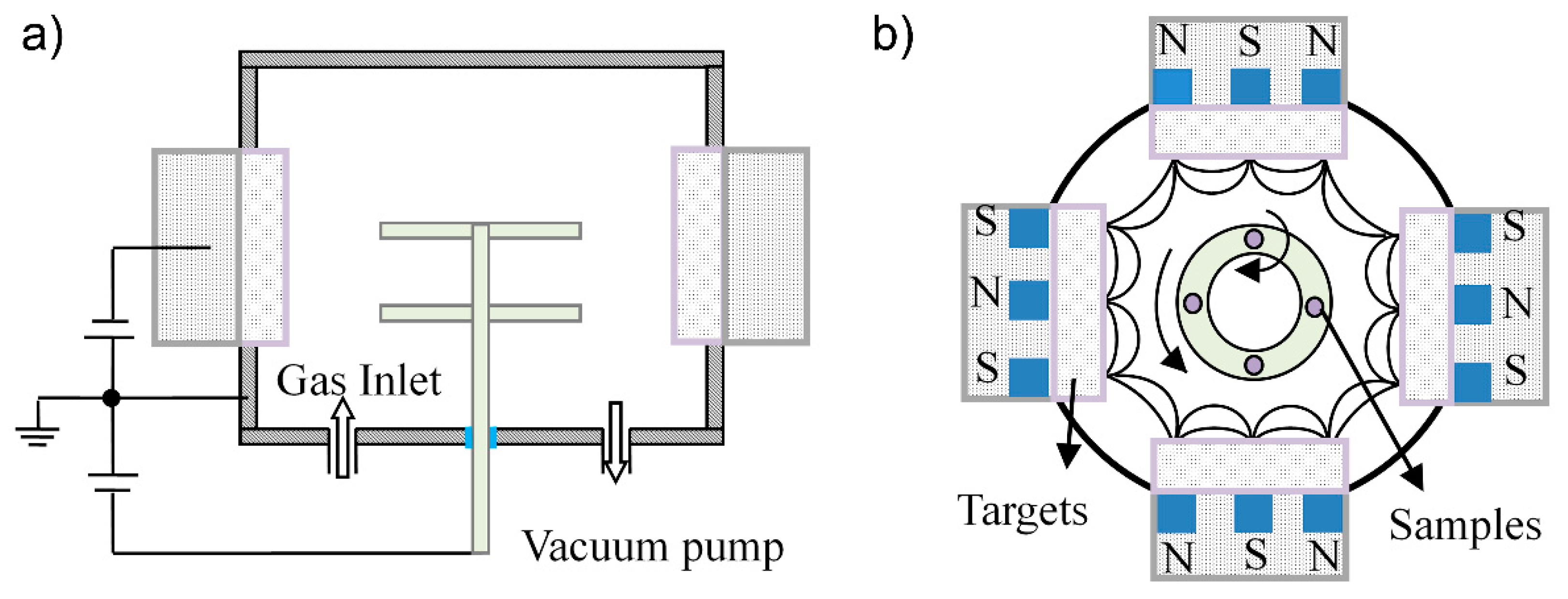
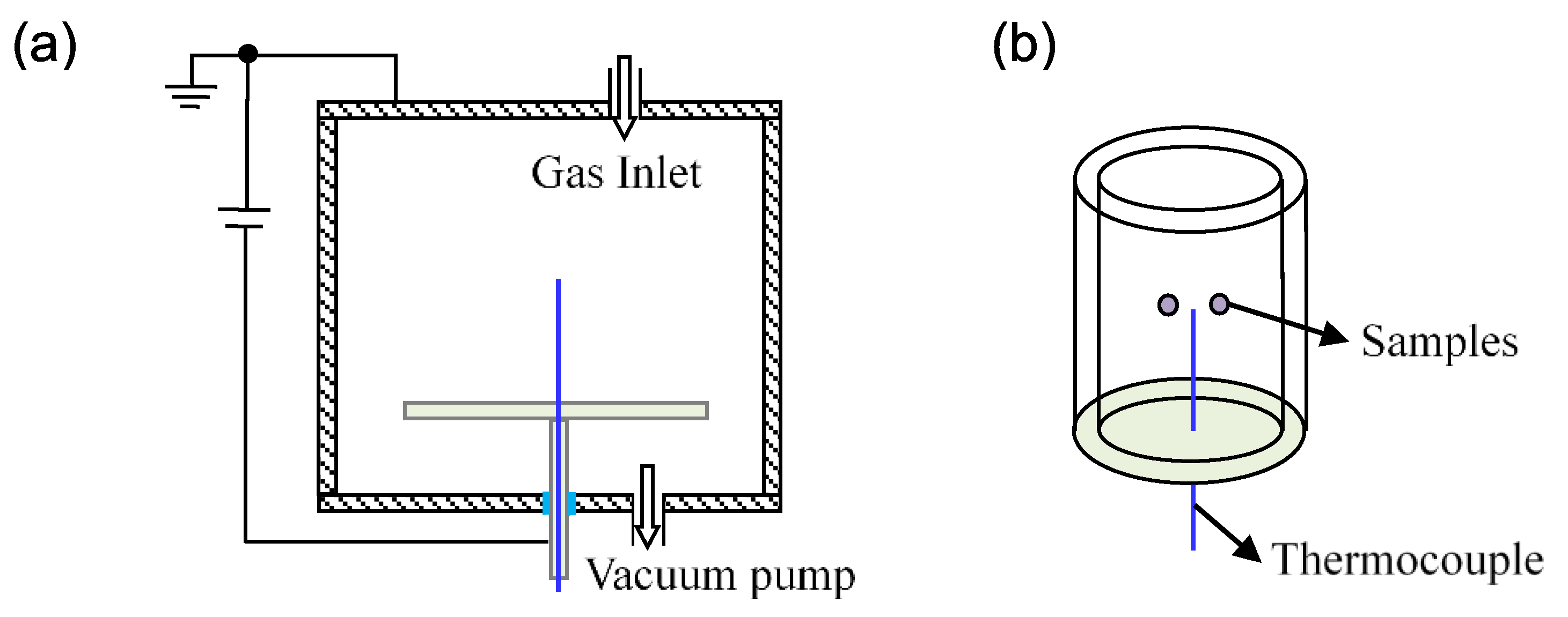
2.1. Experimental Material and Method
2.2. Characterization
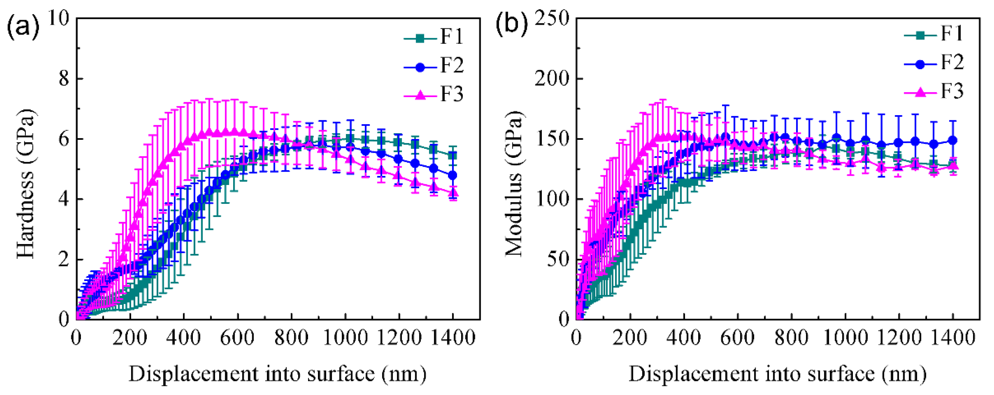
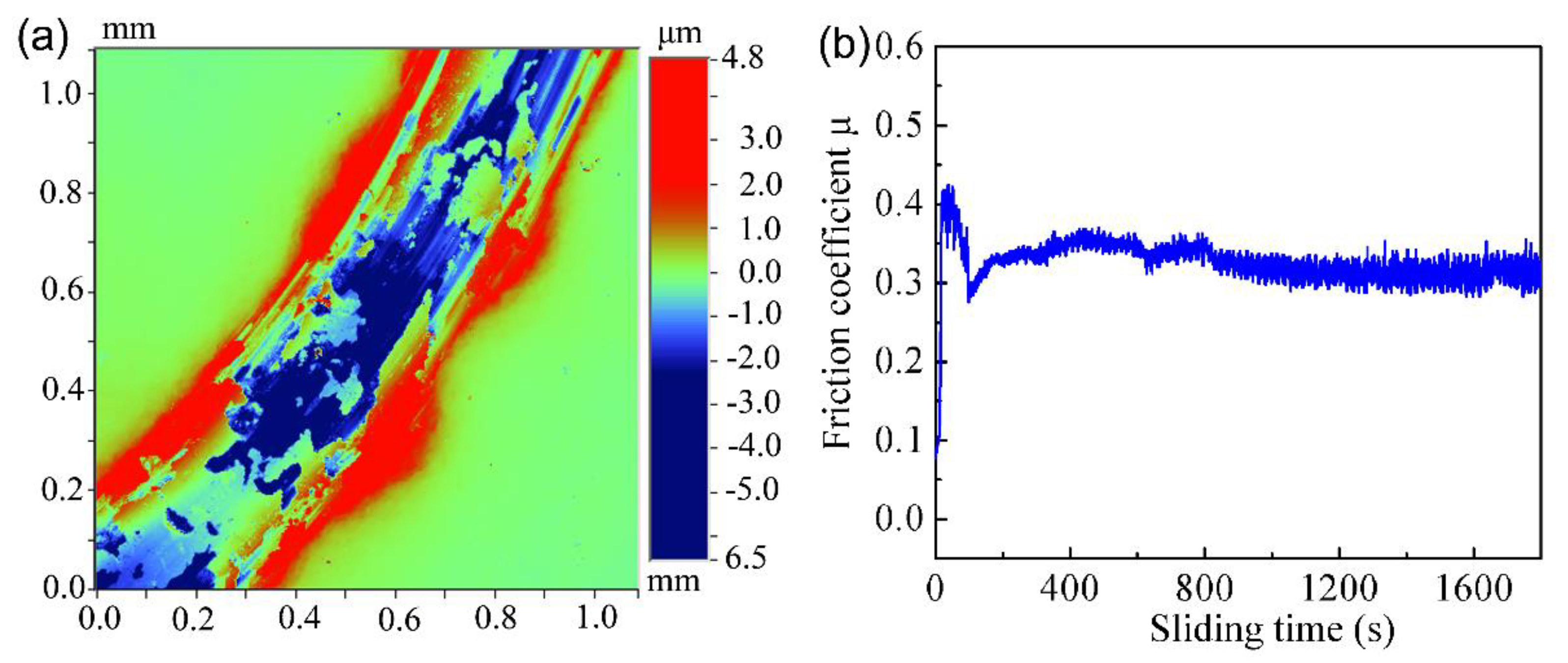
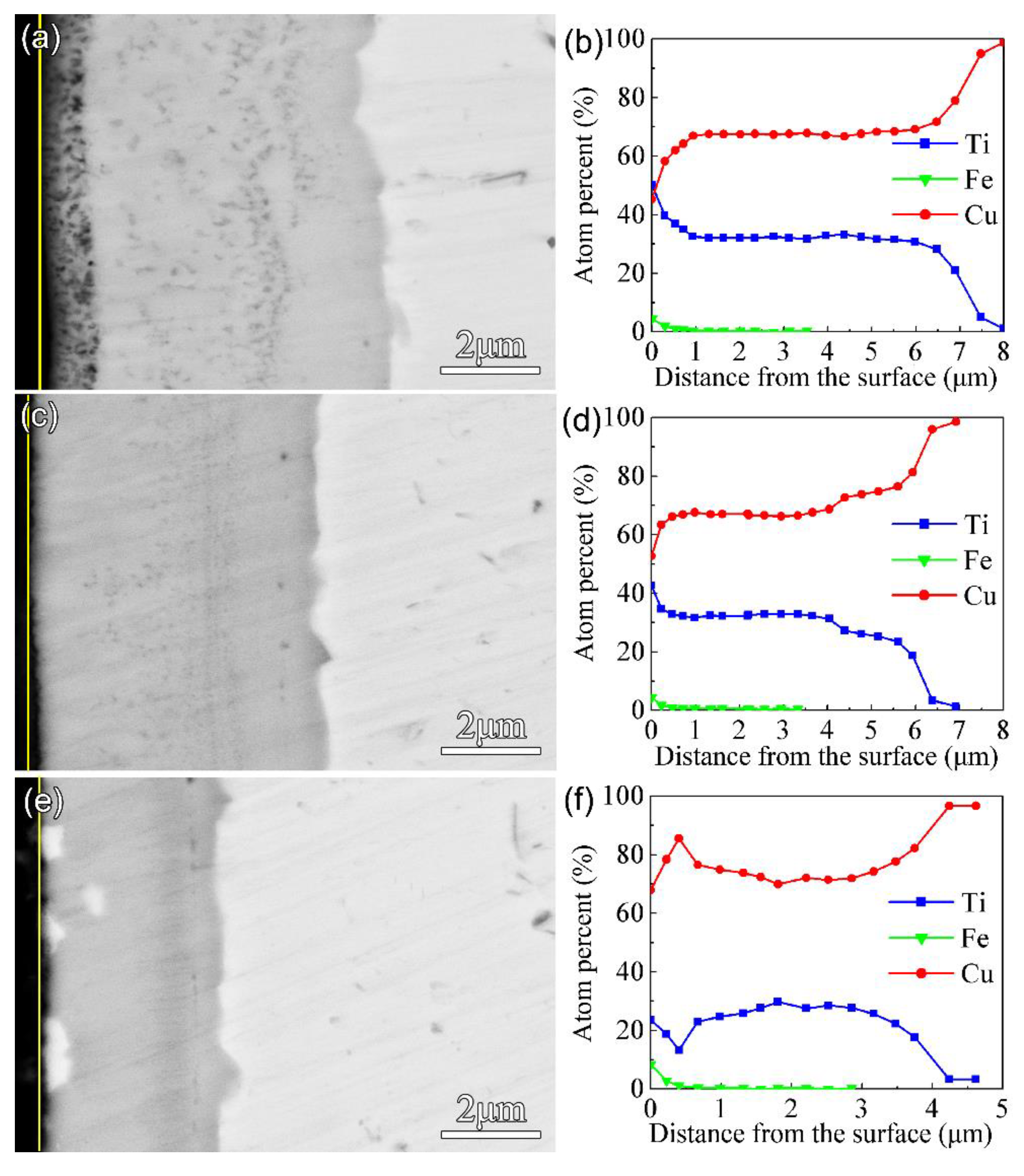
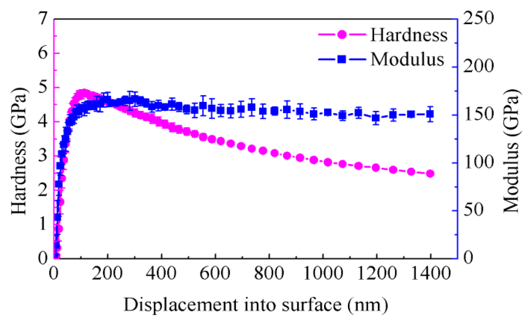
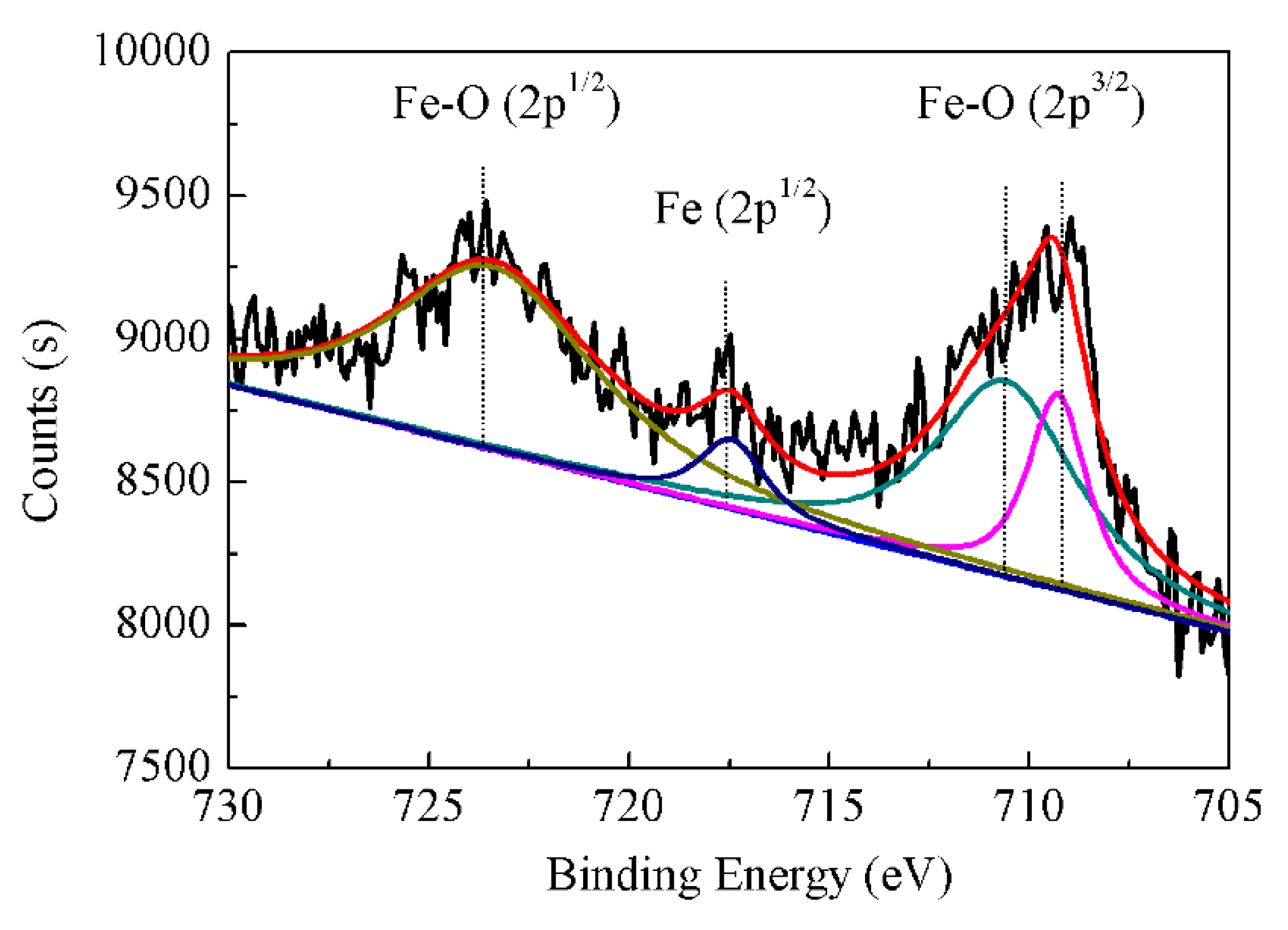
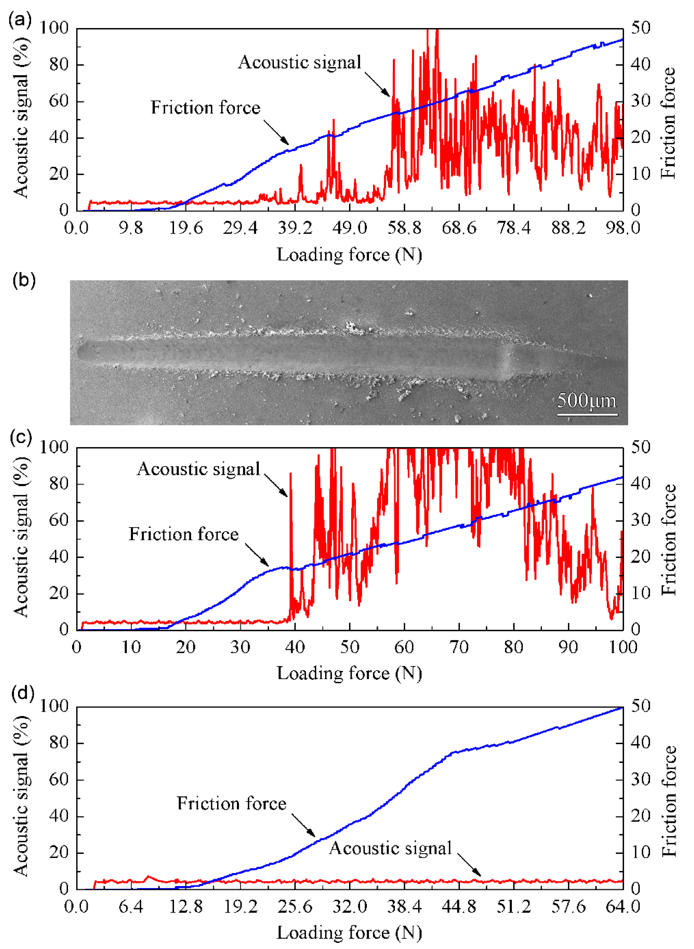
3. Results and Discussion
4. Conclusions
- (1)
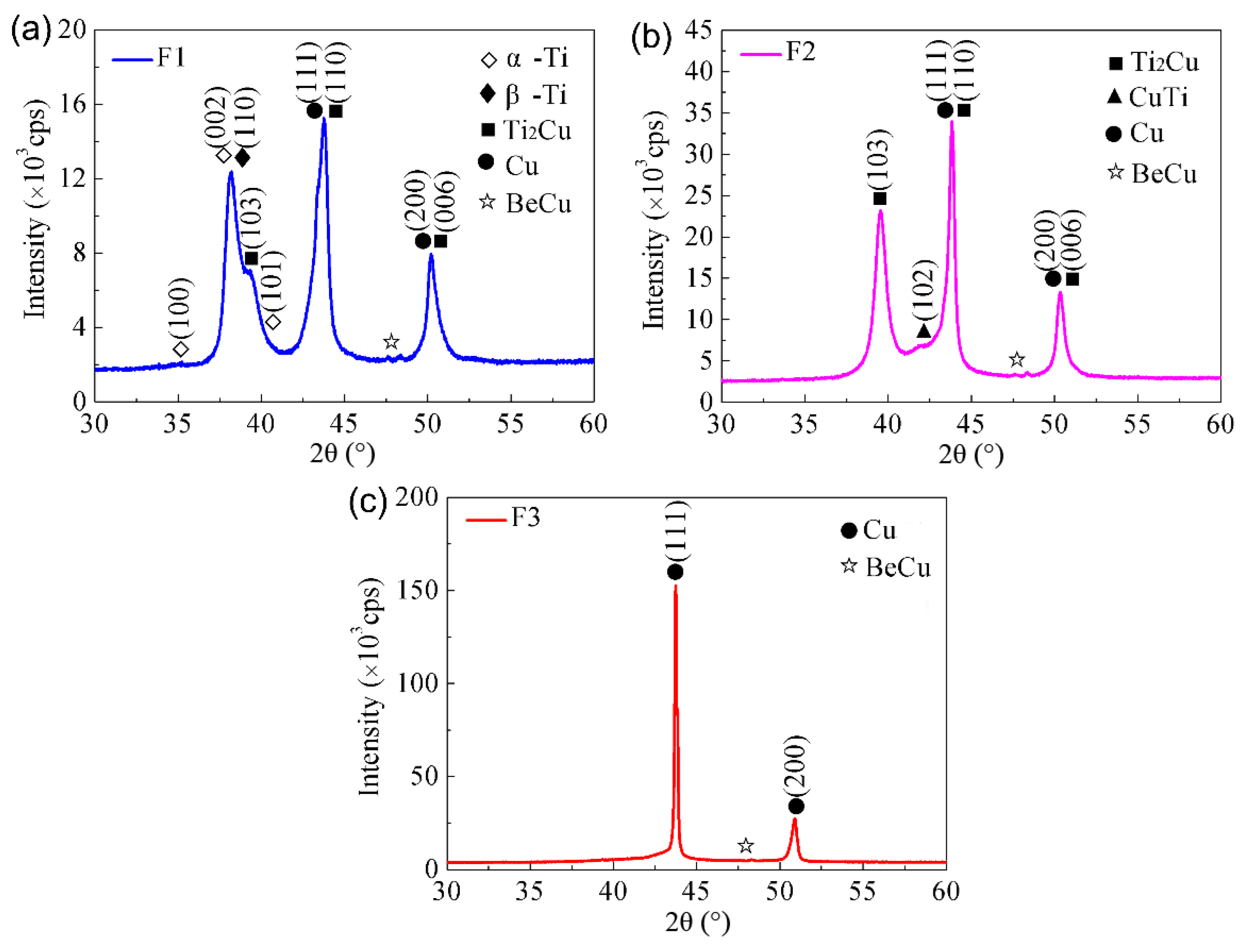
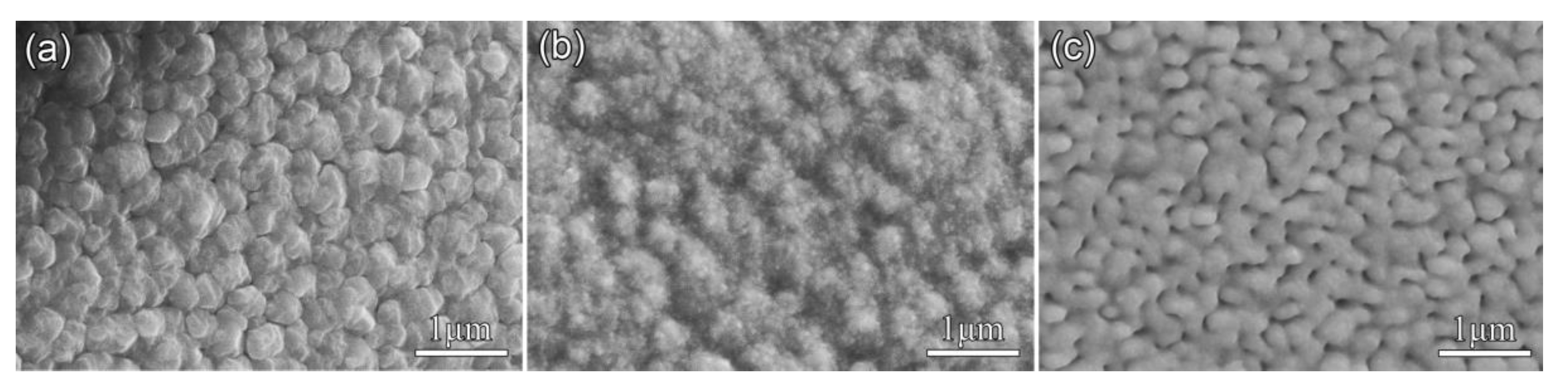
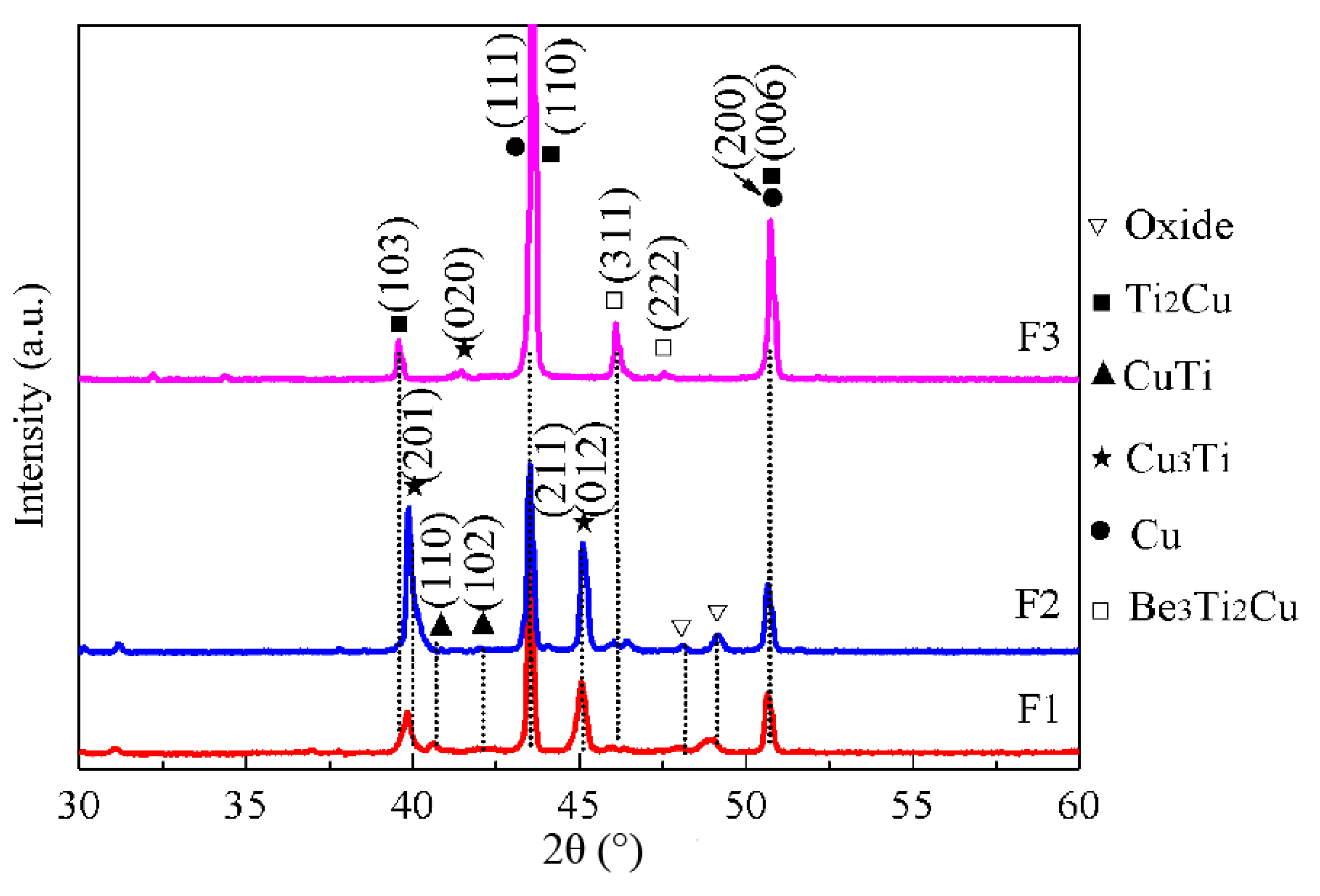
- Three types of Cu-Ti films with different elemental composition were fabricated. Both the surface morphology and the formed phases during magnetron sputtering changed for the varying Cu/Ti atom ratio;
- (2)
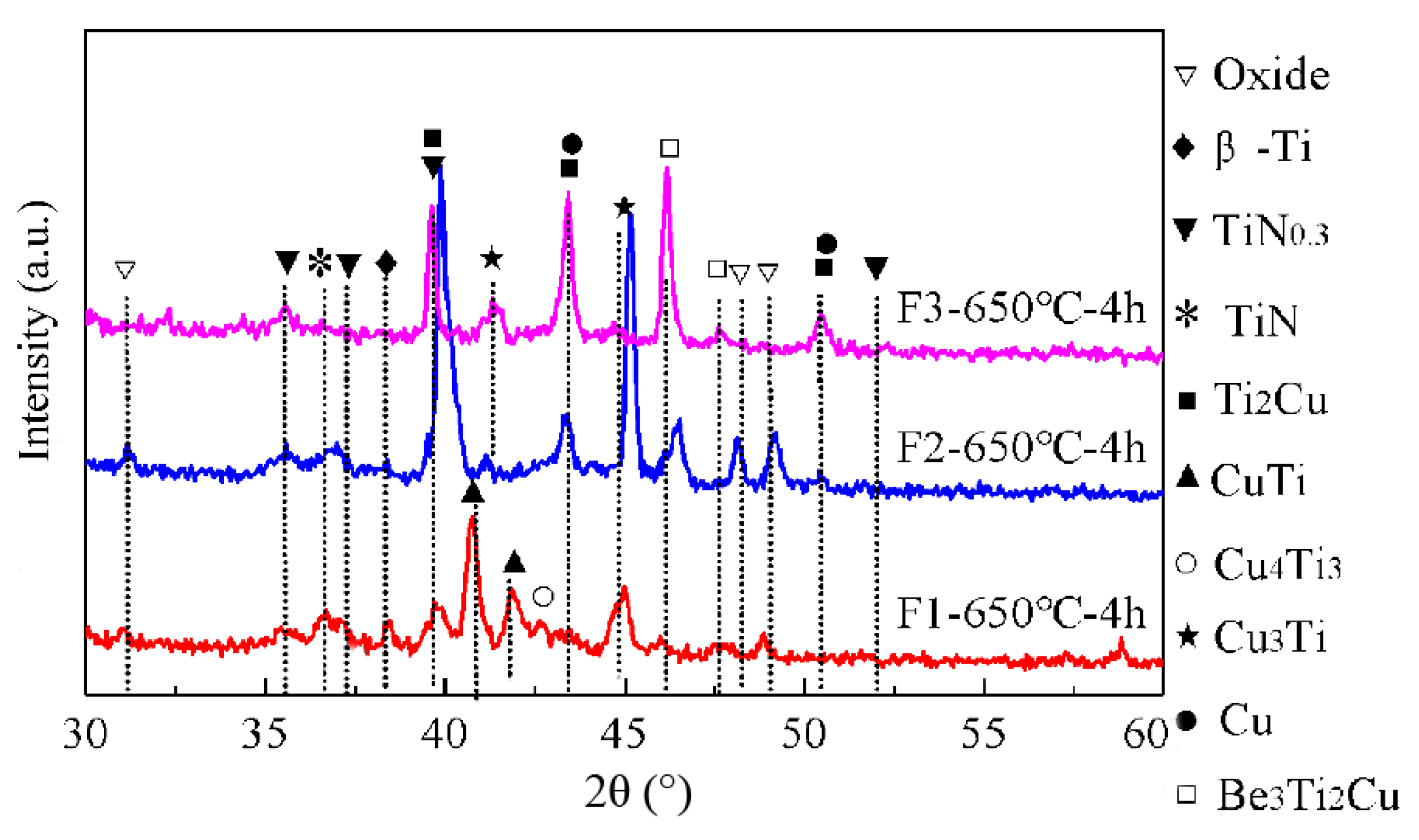
- The composition of the multiphase coating after plasma nitriding is closely dependent on the Cu/Ti atom ratio of the prefabricated gradient Cu-Ti films, where small amounts of Ti-N compounds and the specific Cu-Ti intermetallics formed in the three types of Cu-Ti films;
- (3)
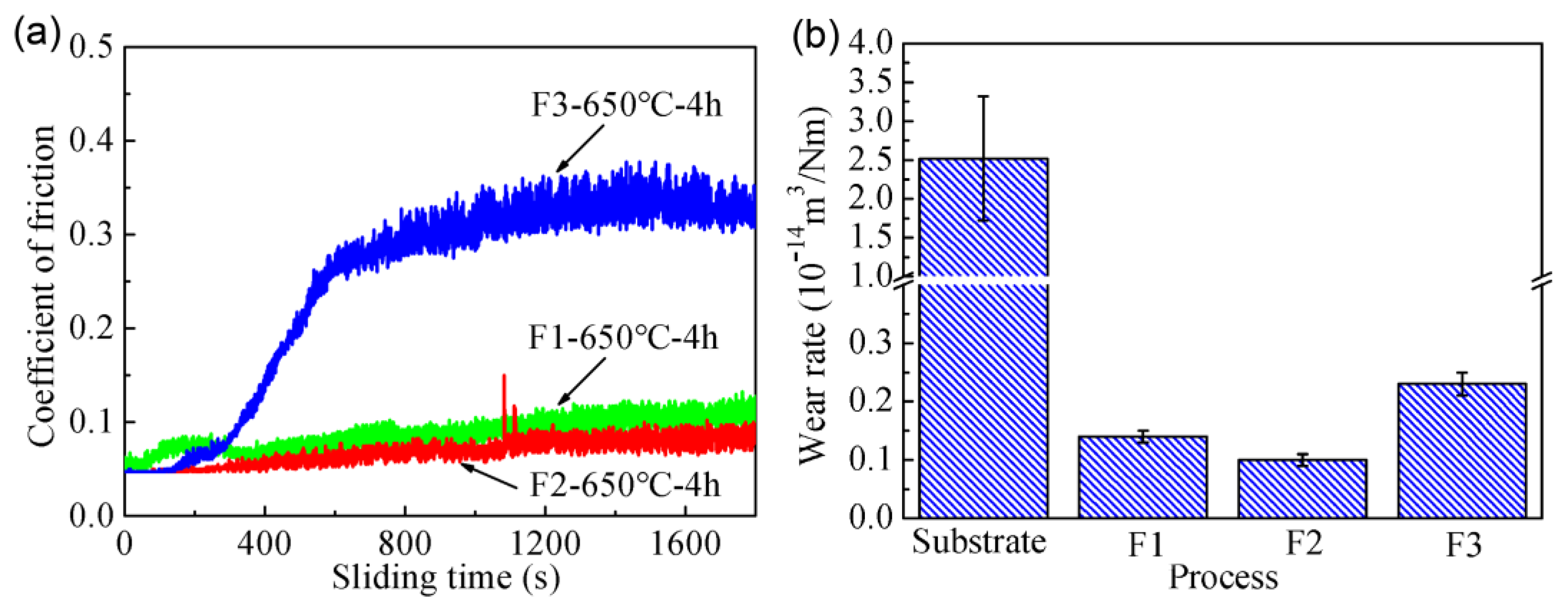
- The friction coefficient and the wear resistance of the C17200 Cu alloys were obviously improved by the plasma nitriding of the prefabricated Cu-Ti film on C17200 Cu alloy, where the friction coefficient could reach 0.06 and the wear rate reached 90 % lower than that of the substrate. In addition, a satisfactory adhesive force was obtained for the gradually changed mechanical properties of the coating.
Author Contributions
Funding
Acknowledgments
Conflicts of Interest
References
- Fouquet, V.; Pichon, L.; Drouet, M.; Straboni, A. Plasma assisted nitridation of Ti-6Al-4V. Appl. Surf. Sci. 2004, 221, 248–258. [Google Scholar] [CrossRef]
- Oktay, S.; Kahraman, Z.; Urgen, M.; Kazmanli, K. XPS investigations of tribolayers formed on Ti and (Ti,Re)N coatings. Appl. Surf. Sci. 2015, 328, 255–261. [Google Scholar] [CrossRef]
- Yilbaş, B.S.; Şahin, A.Z.; Al-Garni, A.Z.; Said, S.A.M.; Ahmed, Z.; Abdulaleem, B.J.; Sami, M. Plasma nitriding of Ti-6Al-4V alloy to improve some tribological properties. Surf. Coat. Technol. 1996, 80, 287–292. [Google Scholar] [CrossRef]
- Mubarak Ali, M.; Ganesh Sundara Raman, S.; Pathak, S.D.; Gnanamoorthy, R. Influence of plasma nitriding on fretting wear behaviour of Ti–6Al–4V. Tribol. Int. 2010, 43, 152–160. [Google Scholar] [CrossRef]
- Kuo, C.; Lin, Y.; Chan, A.; Chang, J. High temperature wear behavior of titanium nitride coating deposited using high power impulse magnetron sputtering. Coatings 2019, 9, 555. [Google Scholar] [CrossRef]
- Adachi, S.; Ueda, N. Wear and corrosion properties of cold-sprayed AISI 316L coatings treated by combined plasma carburizing and nitriding at low temperature. Coatings 2018, 8, 456. [Google Scholar] [CrossRef]
- Yan, M.F.; Zhu, Y.D.; Zhang, C.S.; Zhang, Y.X.; Wang, Y.X.; Yang, L. Microstructure and mechanical properties of copper-titanium-nitrogen multiphase layers produced by a duplex treatment on C17200 copper-beryllium alloy. Mater. Des. 2015, 84, 10–17. [Google Scholar] [CrossRef]
- Liu, L.; Shen, H.H.; Liu, X.Z.; Guo, Q.; Meng, T.X.; Wang, Z.X.; Yang, H.J.; Liu, X.P. Wear resistance of TiN (Ti2N)/Ti composite layer formed on C17200 alloy by plasma surface Ti-alloying and nitriding. Appl. Surf. Sci. 2016, 388, 103–108. [Google Scholar] [CrossRef]
- Zhu, Y.D.; Yan, M.F.; Zhang, Y.X.; Chen, H.T.; Yang, Y. Microstructure formation and evolution mechanism of Cu-Ti coating during dual-magnetron sputtering and thermo plasma nitriding. Vacuum 2016, 134, 25–28. [Google Scholar] [CrossRef]
- Taweesub, K.; Visuttipitukul, P.; Tungkasmita, S.; Paosawatyanyong, B. Nitridation of Al–6%Cu alloy by Rf plasma process. Surf. Coat. Technol. 2010, 204, 3091–3095. [Google Scholar] [CrossRef]
- Yang, L.; Zhang, F.Y.; Yan, M.F.; Zhang, M.L. Microstructure and mechanical properties of multiphase layer formed during thermo-diffusing of titanium into the surface of C17200 copper-beryllium alloy. Appl. Surf. Sci. 2014, 292, 225–230. [Google Scholar] [CrossRef]
- Kim, Y.S.; Park, H.J.; Mun, S.C.; Jumaev, E.; Hong, S.H.; Song, G.; Kim, J.T.; Park, Y.K.; Kim, K.S.; Jeong, S.I.; et al. Investigation of structure and mechanical properties of TiZrHfNiCuCo high entropy alloy thin films synthesized by magnetron sputtering. J. Alloy Compd. 2019, 797, 834–841. [Google Scholar] [CrossRef]
- Zhu, Y.D.; Yao, J.W.; Yan, M.F.; Zhang, Y.X.; Wang, Y.X.; Yang, Y.; Yang, L. High temperature plasma nitriding to modify Ti coated C17200 Cu surface: Microstructure and tribological properties. Vacuum 2018, 147 (Suppl. C), 163–171. [Google Scholar] [CrossRef]
- Ghosh, G. First-principles calculations of structural energetics of Cu–Tm (Tm = Ti, Zr, Hf) intermetallics. Acta Mater. 2007, 55, 3347–3374. [Google Scholar] [CrossRef]
- Zhu, Y.D.; Yan, M.F.; Zhang, Y.X.; Zhang, C.S. First-principles investigation of structural, mechanical and electronic properties for Cu–Ti intermetallics. Comp. Mater. Sci. 2016, 123, 70–78. [Google Scholar] [CrossRef]
- Zhu, Y.D.; Yan, M.F.; Zhang, Y.X.; Zhang, C.S. Surface modification of C17200 copper-beryllium alloy by plasma nitriding of Cu-Ti gradient film. J. Mater. Eng. Perform. 2018, 27, 961–969. [Google Scholar] [CrossRef]
- Balashabadi, P.; Larijani, M.M.; Jafari-Khamse, E.; Seyedi, H. The role of Cu content on the structural properties and hardness of TiN-Cu nanocomposite film. J. Alloy. Compd. 2017, 728 (Suppl. C), 863–871. [Google Scholar] [CrossRef]
- Wang, X.Q.; Zhao, Y.H.; Yu, B.H.; Xiao, J.Q.; Li, F.Q. Deposition, structure and hardness of Ti-Cu-N hard films prepared by pulse biased arc ion plating. Vacuum 2011, 86, 415–421. [Google Scholar] [CrossRef]
- Joshi, V.A. Titanium Alloys: An Atlas of Structures and Fracture Features; CRC Press: Boca Raton, FL, USA, 2006. [Google Scholar]
- Wang, Y.X.; Yan, M.F.; Li, B.; Guo, L.X.; Zhang, C.S.; Zhang, Y.X.; Bai, B.; Chen, L.; Long, Z.; Li, R.W. Surface properties of low alloy steel treated by plasma nitrocarburizing prior to laser quenching process. Opt. Laser Technol. 2015, 67, 57–64. [Google Scholar] [CrossRef]
- Voyiadjis, G.Z.; Peters, R. Size effects in nanoindentation: An experimental and analytical study. Acta Mech. 2009, 211, 131–153. [Google Scholar] [CrossRef]
- Almasri, A.H.; Voyiadjis, G.Z. Nano-indentation in FCC metals: Experimental study. Acta Mech. 2009, 209, 1–9. [Google Scholar] [CrossRef]
- Elmustafa, A.A.; Stone, D.S. Nanoindentation and the indentation size effect: Kinetics of deformation and strain gradient plasticity. J. Mech. Phys. Solids 2003, 51, 357–381. [Google Scholar] [CrossRef]
- Kim, J.T.; Hong, S.H.; Park, H.J.; Kim, Y.S.; Suh, J.Y.; Lee, J.K.; Park, J.M.; Maity, T.; Eckert, J.; Kim, K.B. Deformation mechanisms to ameliorate the mechanical properties of novel TRIP/TWIP Co-Cr-Mo-(Cu) ultrafine eutectic alloys. Sci. Rep. 2017, 7, 39959. [Google Scholar] [CrossRef] [PubMed]
- Jauberteau, I.; Mayet, R.; Cornette, J.; Mangin, D.; Bessaudou, A.; Carles, P.; Jauberteau, J.L.; Passelergue, A. Silicides and nitrides formation in Ti Films coated on Si and exposed to (Ar-N2-H2) expanding plasma. Coatings 2017, 7, 23. [Google Scholar] [CrossRef]
- Zhou, G.; Zhu, Y.; Wang, X.; Xia, M.; Zhang, Y.; Ding, H. Sliding tribological properties of 0.45% carbon steel lubricated with Fe3O4 magnetic nano-particle additives in baseoil. Wear 2013, 301, 753–757. [Google Scholar] [CrossRef]


| Be | Co | Ni | Fe | Si | Cu |
|---|---|---|---|---|---|
| 1.96 | 0.10 | 0.12 | 0.15 | 0.12 | Bal. |
| Total Ar Pressure (Pa) | Substrate Biases (V) | Sputtering Time (h) | Substrate-to-Target Distance (mm) | Workpiece Speed (rpm) | Substrate Temperature (°C) |
|---|---|---|---|---|---|
| 5 | −70 | 3 | 120 | 5 | 20–150 |
| Process | Ti Target Power (W) | Ti Target Current (A) | Cu Target Power (W) | Cu Target Current (A) |
|---|---|---|---|---|
| F1 | 2500 | 7.00 | 100 | 0.33 |
| F2 | 2000 | 5.69 | 300 | 0.84 |
| F3 | 1000 | 3.02 | 450 | 1.18 |
| Materials | Coating Process | Film Composition | Film Thickness (μm) | |
|---|---|---|---|---|
| Cu (at.%) | Ti (at.%) | |||
| C17200 | F1 | 13 | 87 | 3.3 |
| F2 | 37 | 63 | 3.0 | |
| F3 | 67 | 33 | 2.5 | |
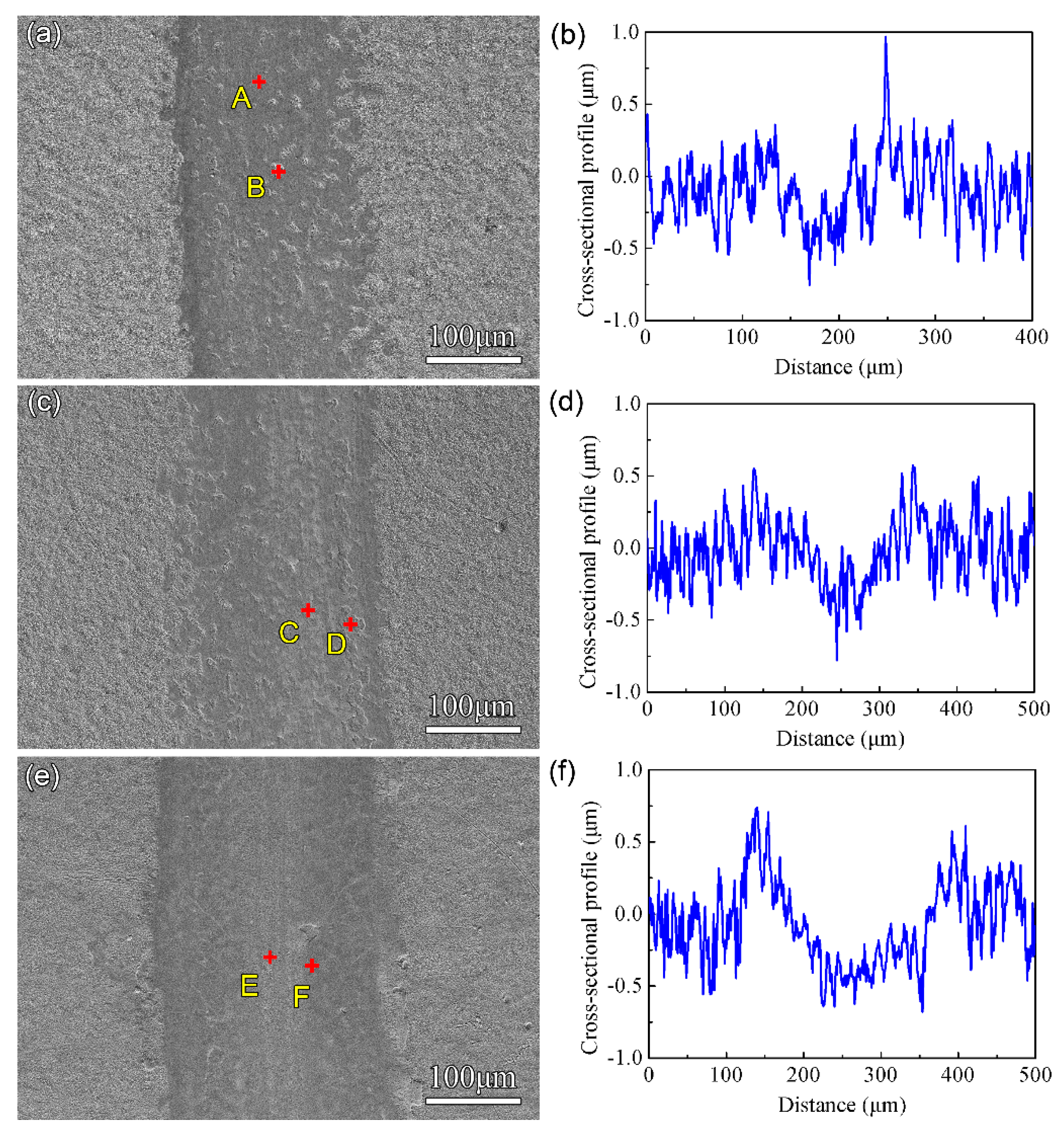
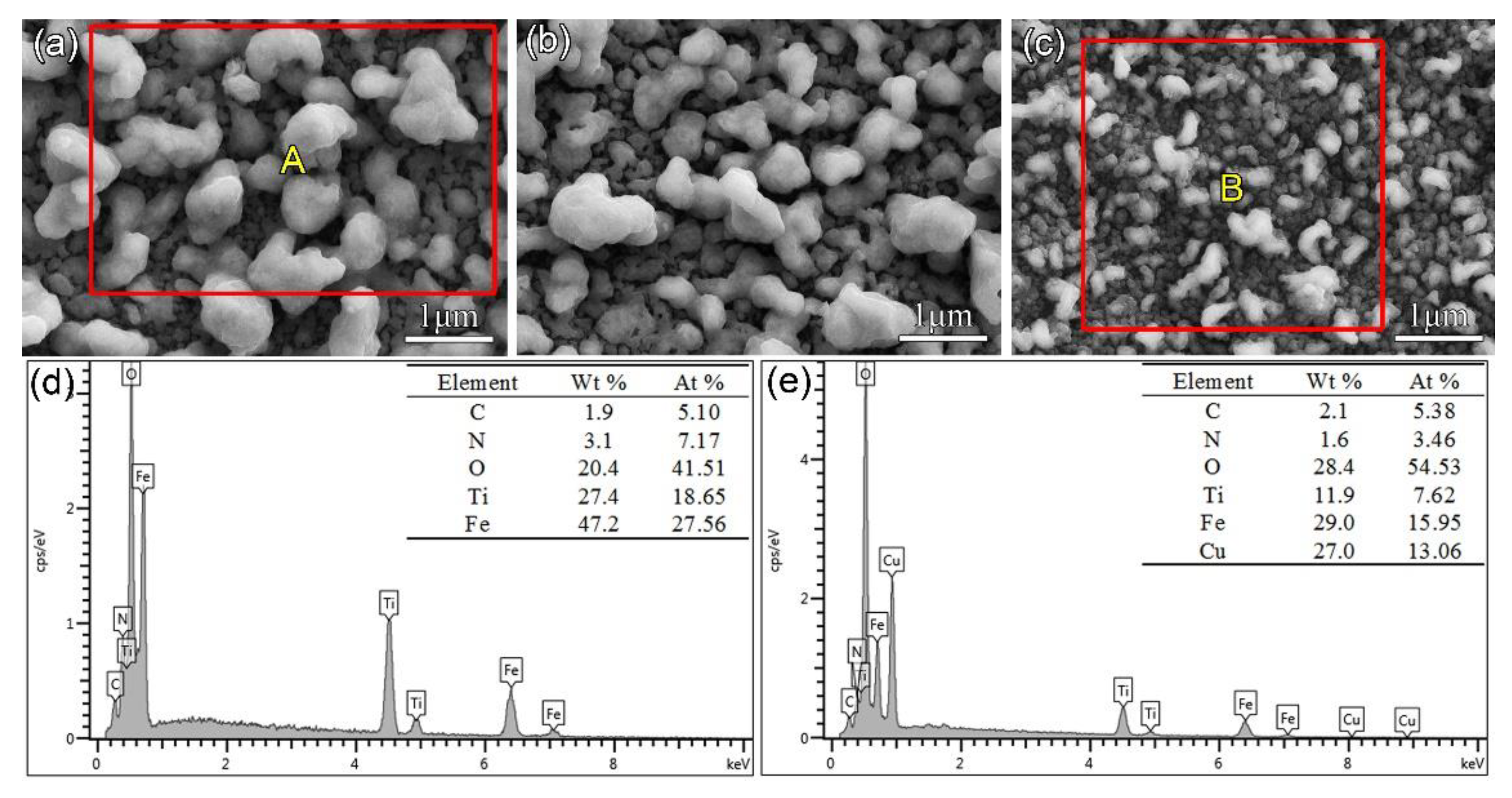
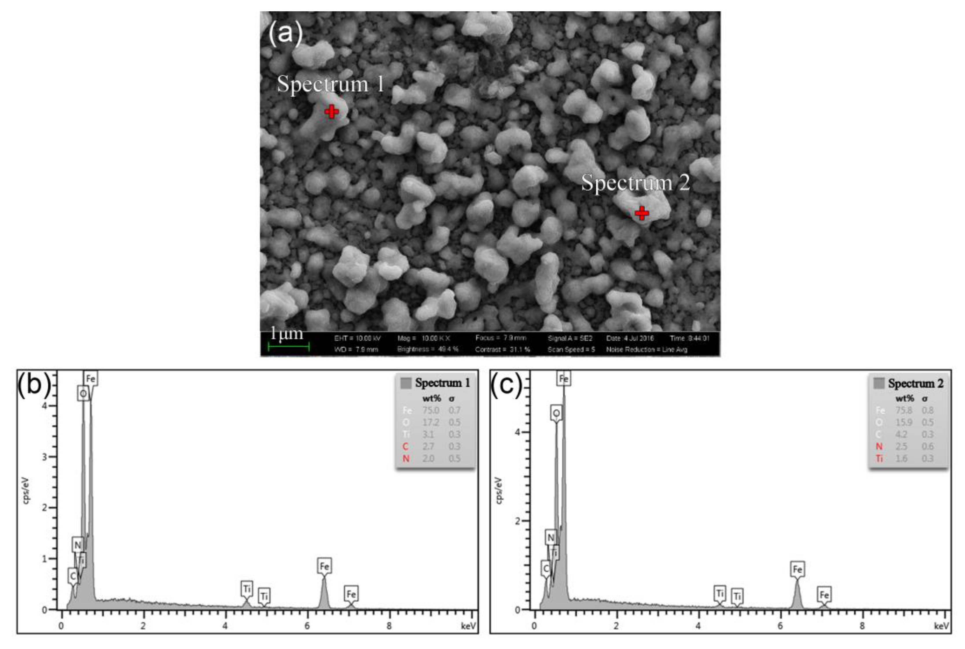
| Elements | C | N | O | Ti | Fe | Cu | W |
|---|---|---|---|---|---|---|---|
| A | 16.98 | - | 49.13 | 18.73 | 7.05 | 7.88 | 0.23 |
| B | 8.97 | 7.3 | 45.39 | 13.72 | 19.28 | 5.34 | - |
| C | 11.81 | - | 60.45 | 12.65 | 11.26 | 1.94 | 1.89 |
| D | 14.77 | 6.75 | 45.52 | 20.96 | 5.02 | 6.98 | - |
| E | 15.51 | - | 60.64 | 5.6 | 8.77 | 6.13 | 3.35 |
| F | 21.09 | - | 51.14 | 6.41 | 9.16 | 12.03 | 0.17 |
© 2019 by the authors. Licensee MDPI, Basel, Switzerland. This article is an open access article distributed under the terms and conditions of the Creative Commons Attribution (CC BY) license (http://creativecommons.org/licenses/by/4.0/).
Share and Cite
Zhu, Y.; Yan, M.; Zhang, Q.; Wang, Q.; Zhuo, H. Effects of the Prefabricated Cu-Ti Film on the Microstructure and Mechanical Properties of the Multiphase Coating by Thermo Plasma Nitriding on C17200 Cu Alloy. Coatings 2019, 9, 694. https://doi.org/10.3390/coatings9110694
Zhu Y, Yan M, Zhang Q, Wang Q, Zhuo H. Effects of the Prefabricated Cu-Ti Film on the Microstructure and Mechanical Properties of the Multiphase Coating by Thermo Plasma Nitriding on C17200 Cu Alloy. Coatings. 2019; 9(11):694. https://doi.org/10.3390/coatings9110694
Chicago/Turabian StyleZhu, Yandan, Mufu Yan, Quanli Zhang, Qiwen Wang, and Hangyu Zhuo. 2019. "Effects of the Prefabricated Cu-Ti Film on the Microstructure and Mechanical Properties of the Multiphase Coating by Thermo Plasma Nitriding on C17200 Cu Alloy" Coatings 9, no. 11: 694. https://doi.org/10.3390/coatings9110694
APA StyleZhu, Y., Yan, M., Zhang, Q., Wang, Q., & Zhuo, H. (2019). Effects of the Prefabricated Cu-Ti Film on the Microstructure and Mechanical Properties of the Multiphase Coating by Thermo Plasma Nitriding on C17200 Cu Alloy. Coatings, 9(11), 694. https://doi.org/10.3390/coatings9110694