
Corrosion and Thermal Fatigue Behaviors of TiC/Ni Composite Coating by Self-Propagating High-Temperature Synthesis in Molten Aluminum Alloy

Abstract
:1. Introduction
2. Materials and Methods
2.1. Materials
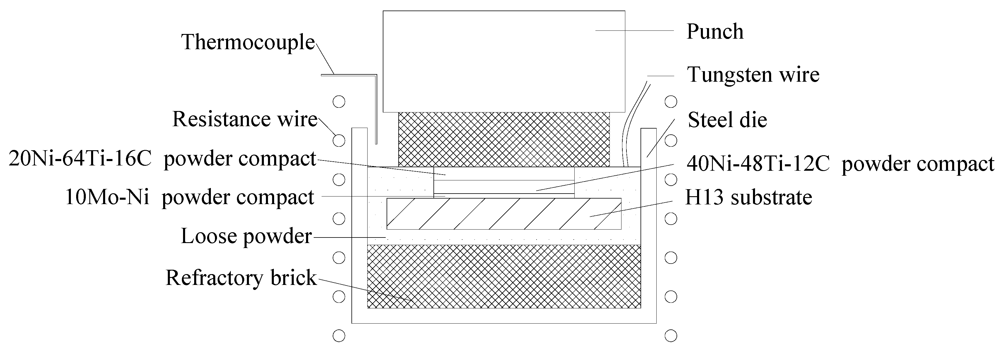
2.2. Coating Procedure
2.3. Characterizations
2.4. Immersion Test
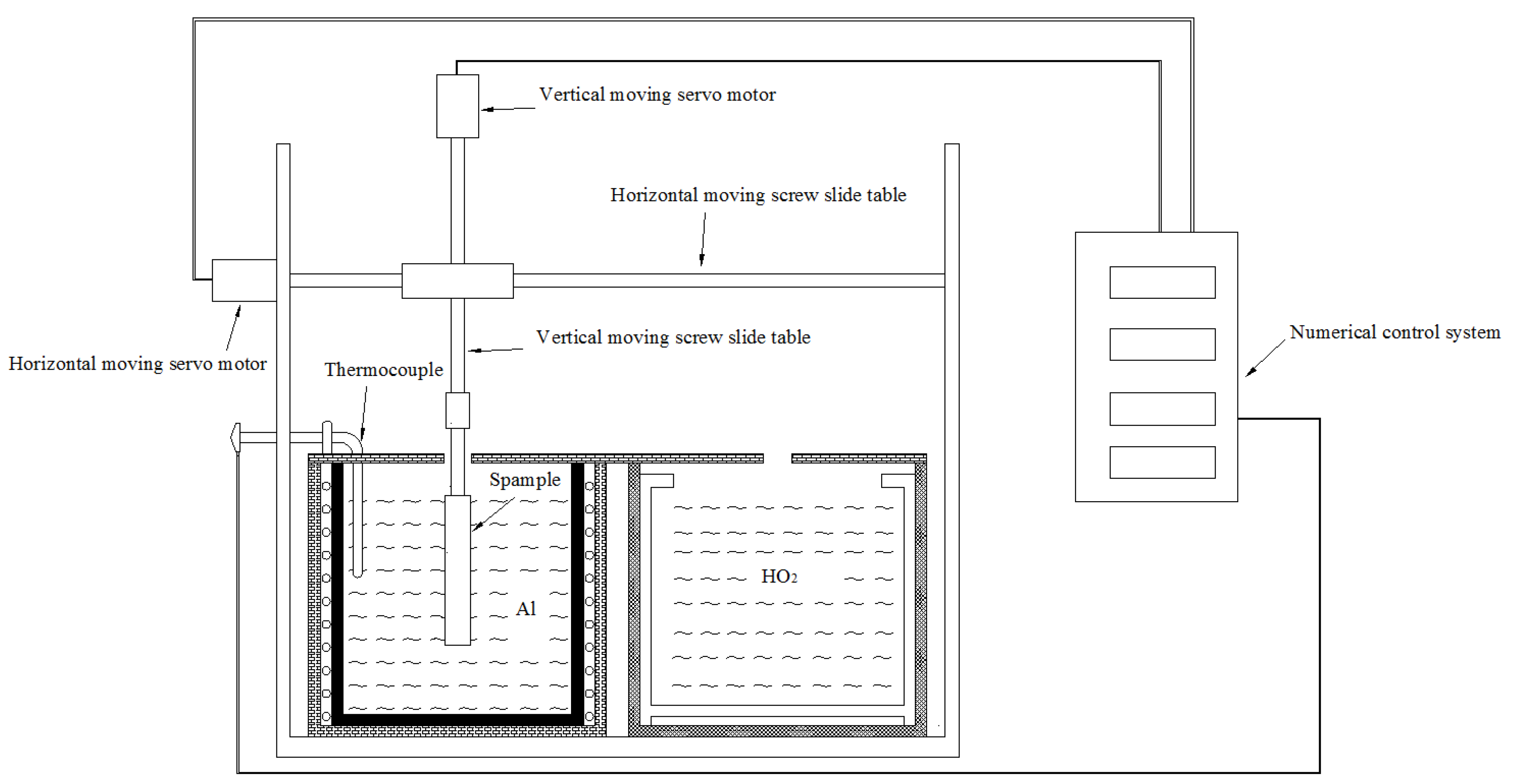
2.5. Thermal Fatigue Test
3. Results and Discussion
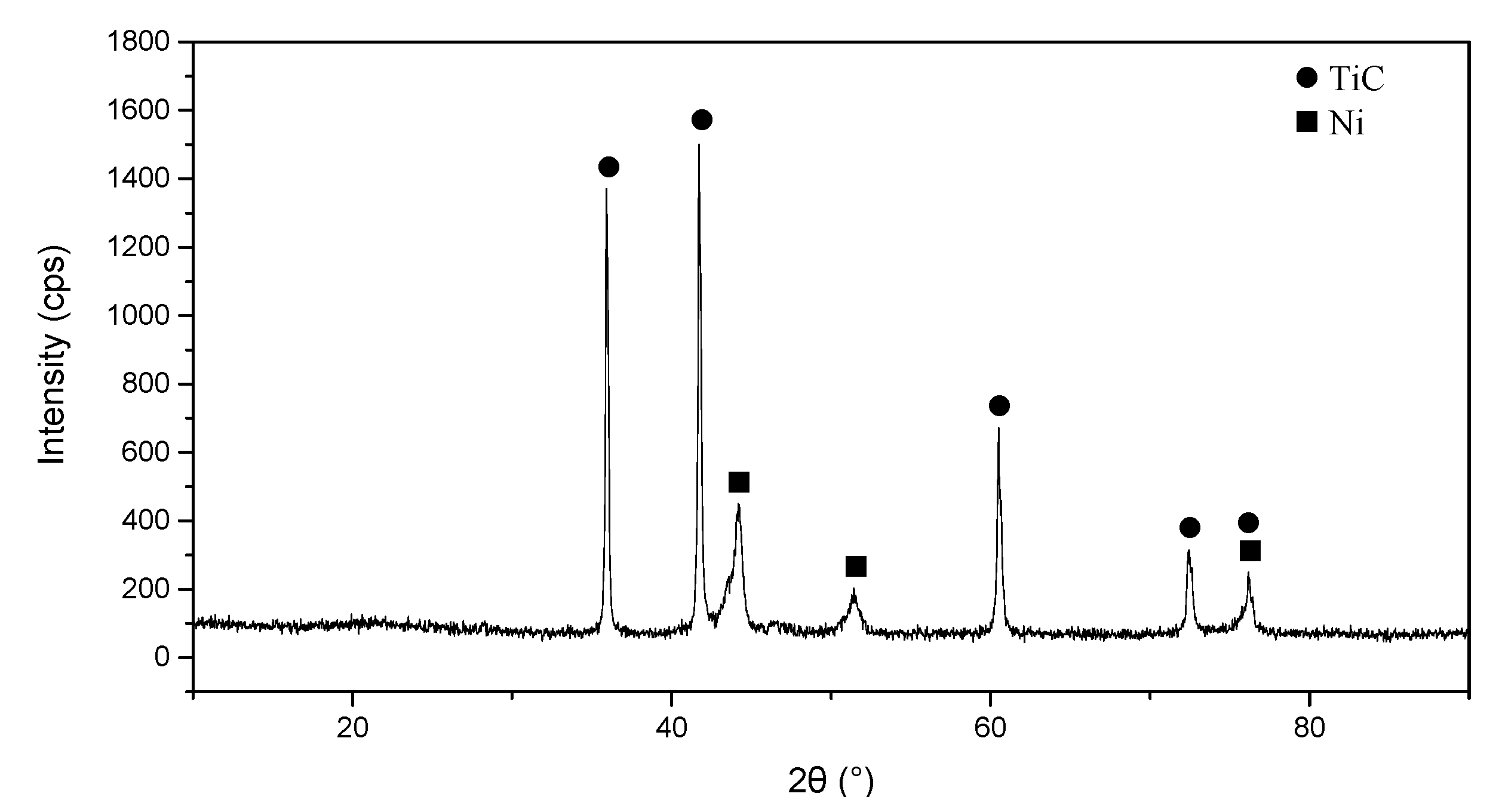
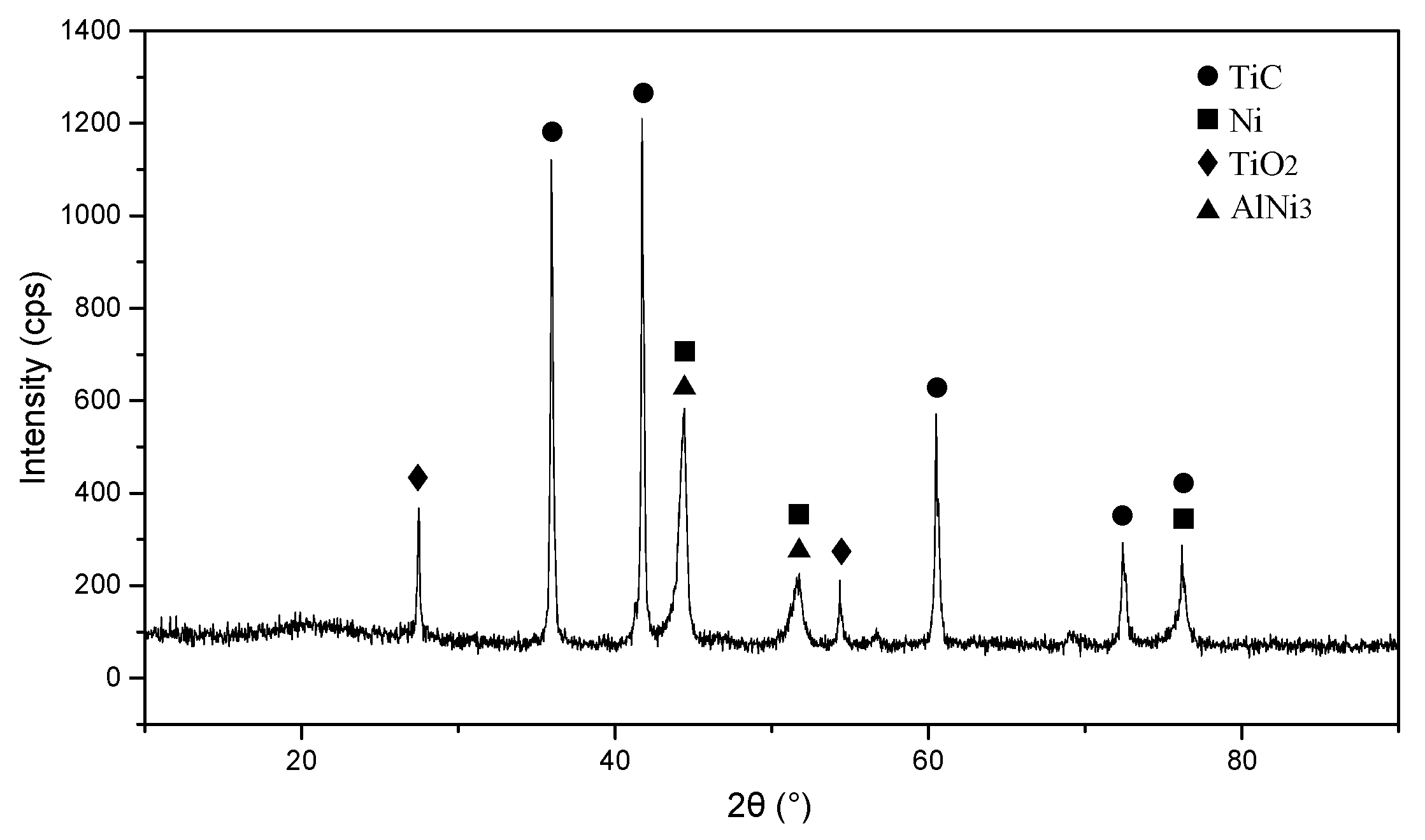
3.1. Phase Analysis
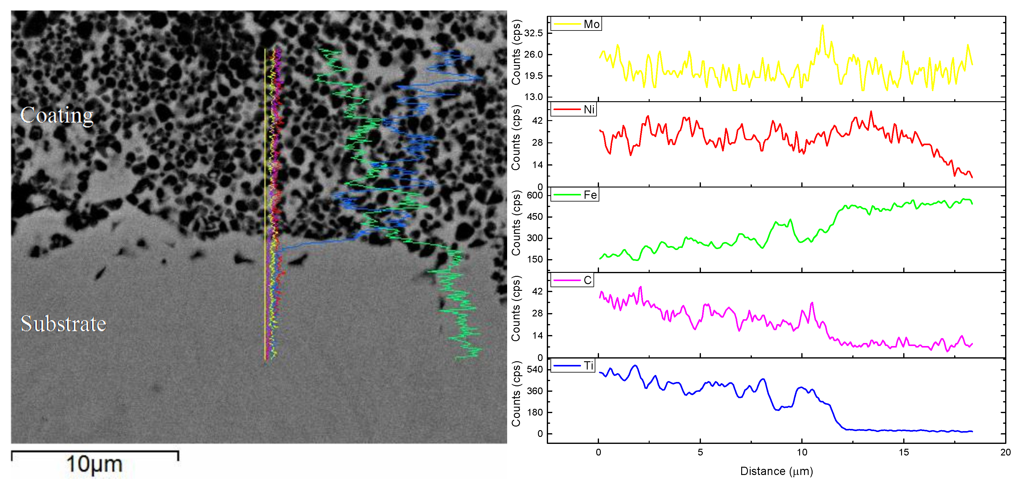
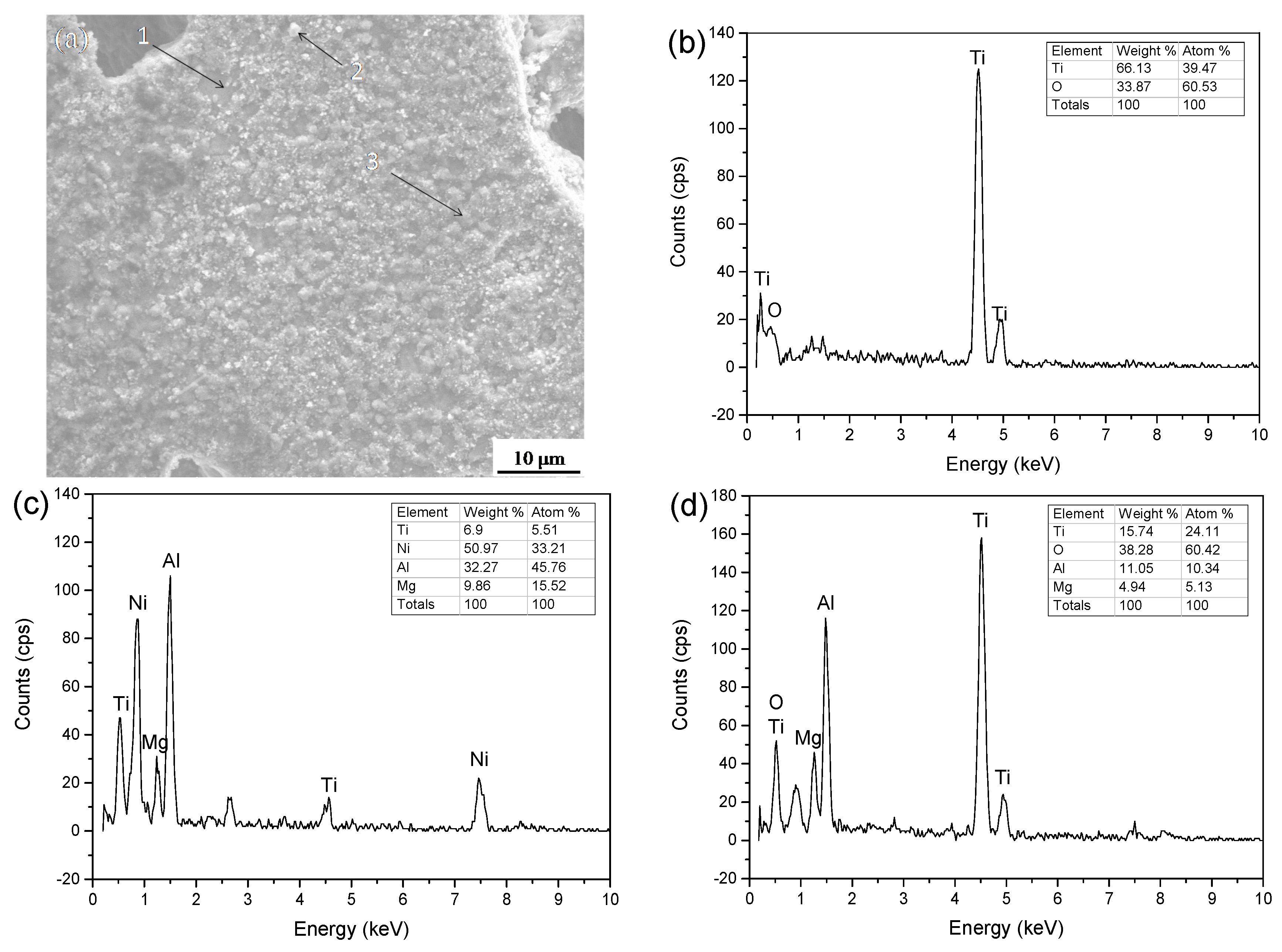
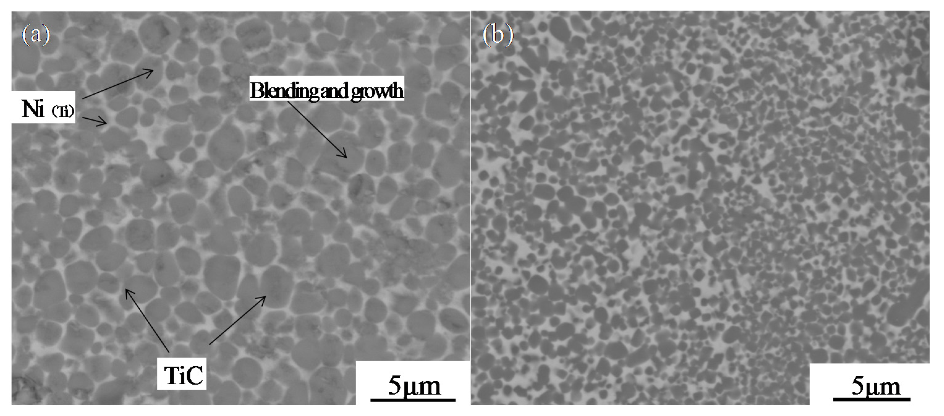
3.2. Microstructural Characterization
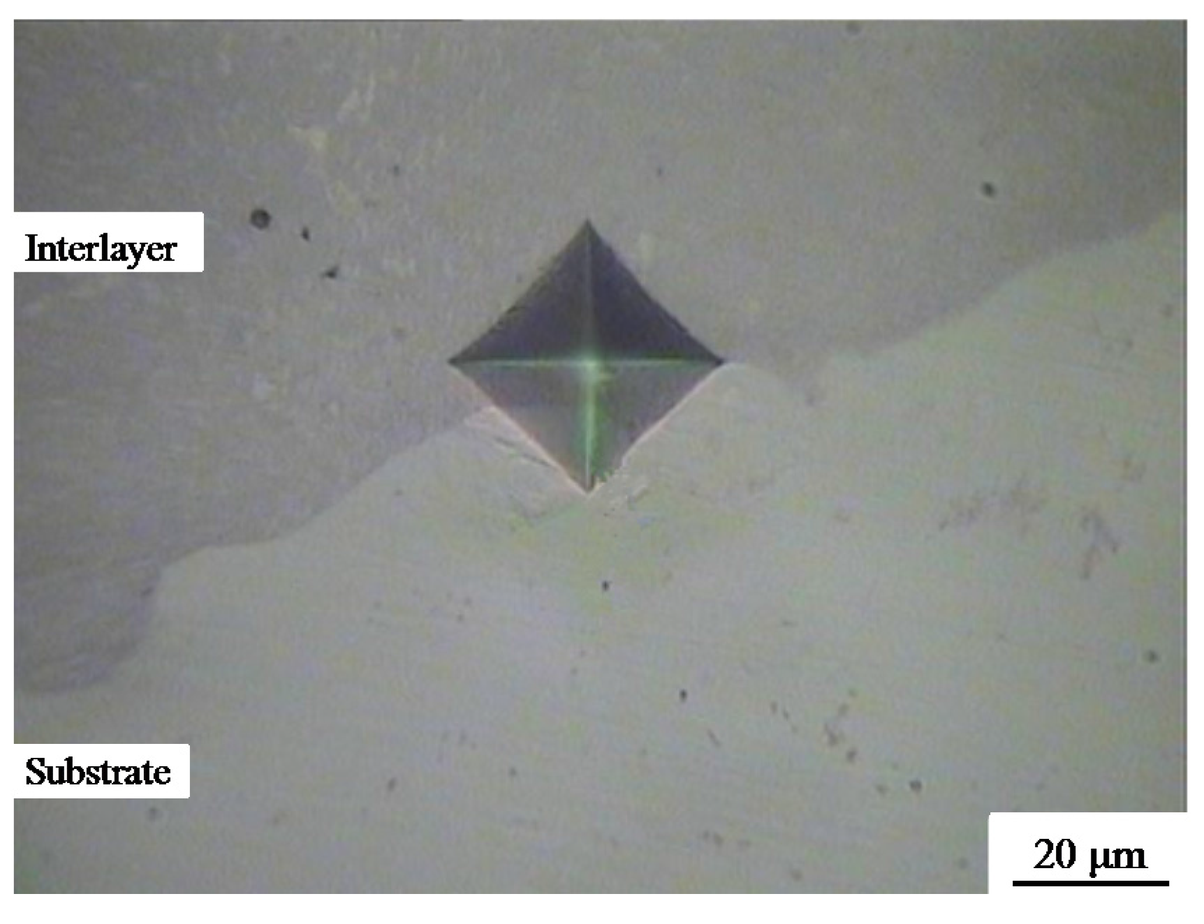
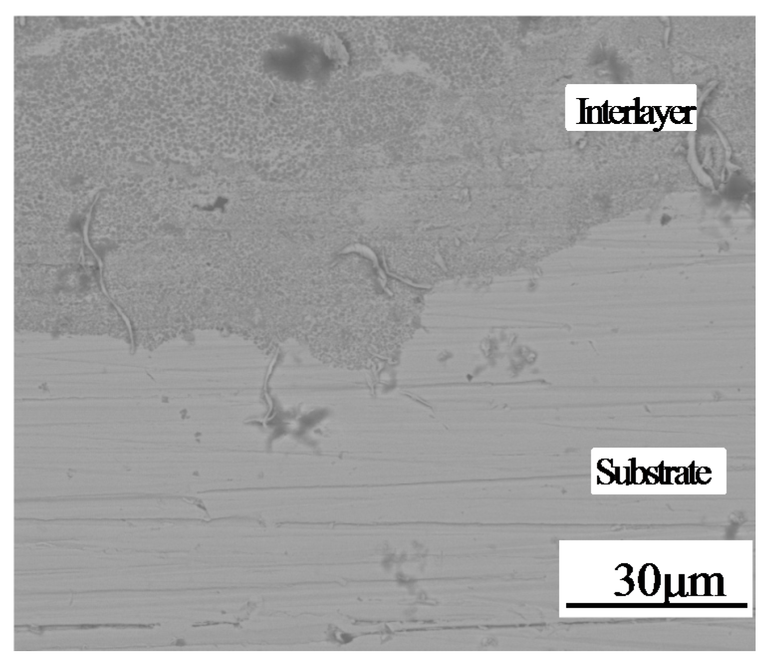
3.3. Bonding Performance and Microhardness
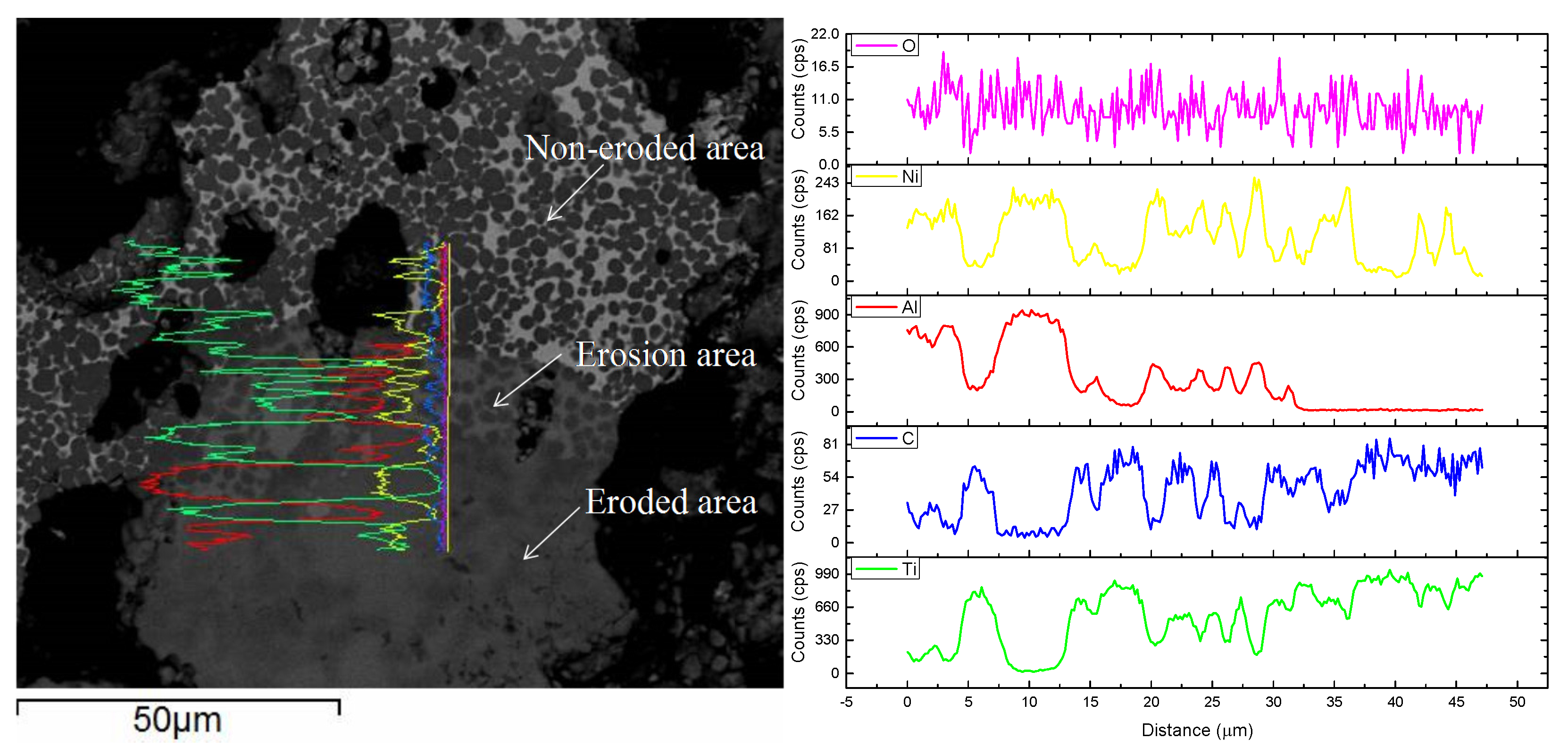
3.4. Immersion Test
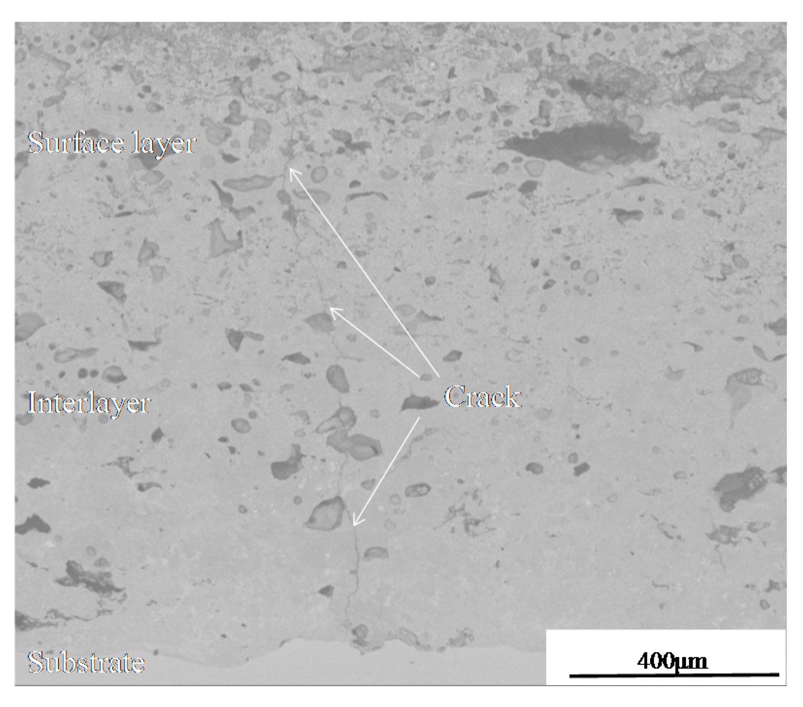
3.5. Thermal Fatigue Test
4. Conclusions
- The in situ coating consisted of the TiC-reinforced phase and Ni binder phase. Spheroidal TiC particles were enveloped by a nearly-continuous Ni binder phase.
- Coating shows good metallurgical bonding in the interface.
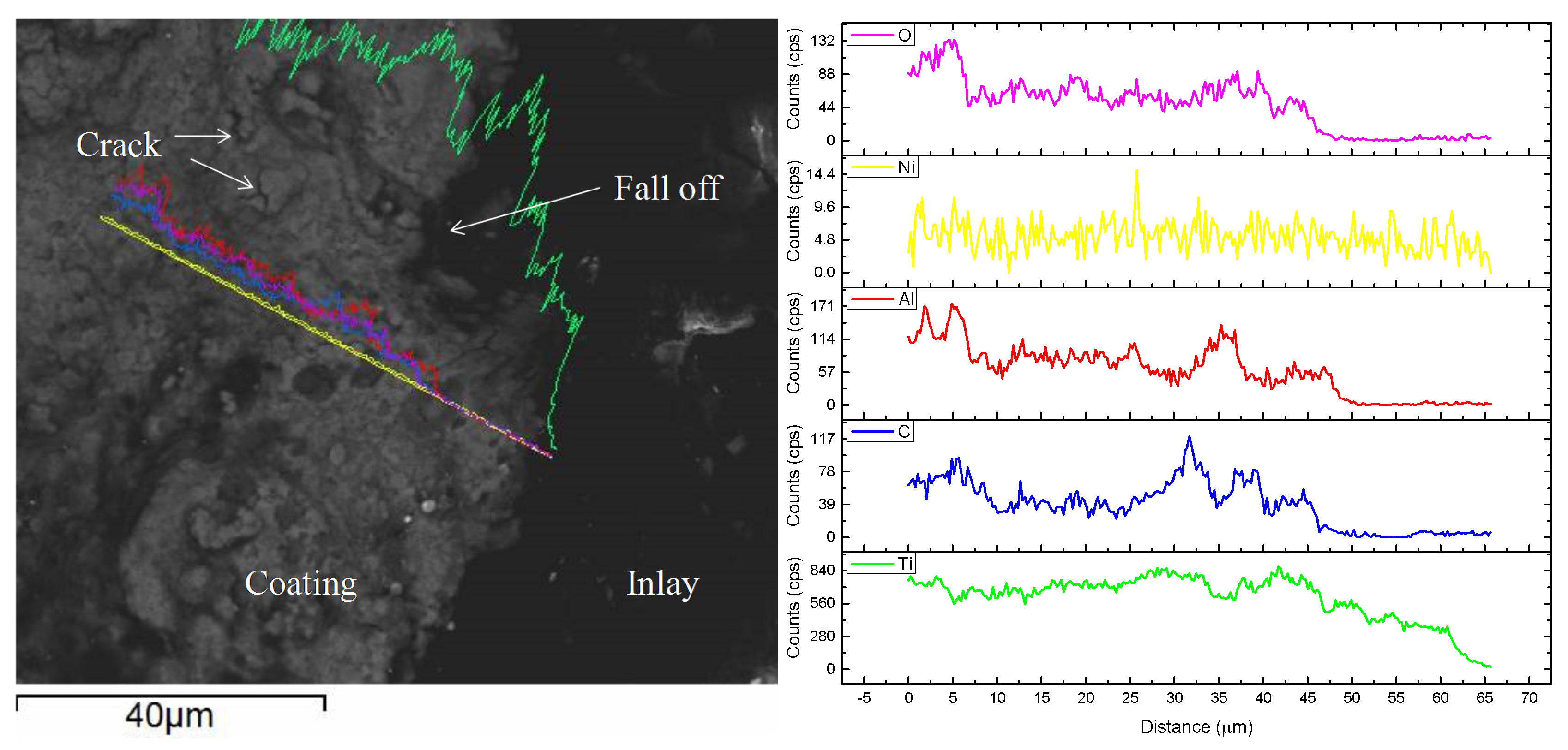
- The corrosive mechanism of the coating surface in molten aluminum alloy involves the Ni binder phase being etched by aluminum to form AlNi3 and the oxidization of the TiC-reinforced phase. The corrosive mechanism that occurred at the corrosive front involves the Ni binder phase of the coating being etched by aluminum to form AlNi3, while the TiC skeleton still maintains the original organizational structure.
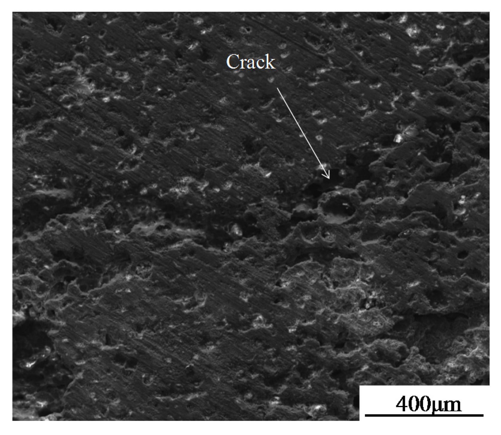
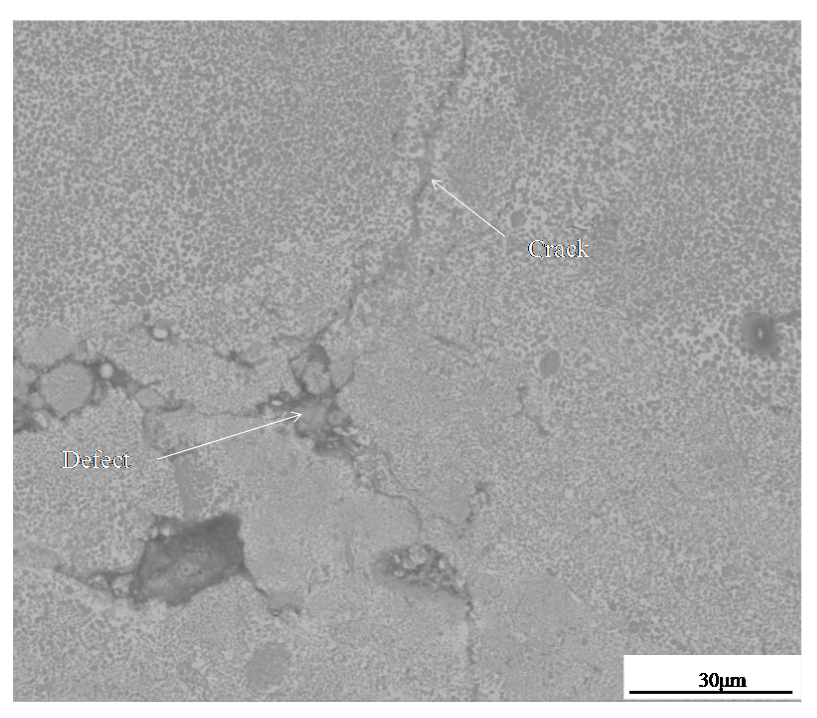
- Hot fatigue cracks began at the defective tips of coating and propagated in the TiC-reinforced phase. The crack is a trans-granular fracture, which is the result of brittle rupture.
Acknowledgments
Author Contributions
Conflicts of Interest
References
- Pirzada, D.; Baburaj, E.G.; Govindaraju, R.; Froes, F.H. Shortlisted laser surface coating of TiC on H13 die steel: Effects on corrosion and errosion behaviour. Surf. Eng. 2000, 16, 164–168. [Google Scholar] [CrossRef]
- Wang, Y. A study of PVD coatings and die materials for extended die-casting die life. Surf. Coat. Technol. 1997, 94–95, 60–63. [Google Scholar] [CrossRef]
- Venkatesan, K.; Shivpuri, R. Experimental and numerical investigation of the effect of process parameters on the erosive wear of die casting dies. J. Mater. Eng. Perform. 1995, 4, 166–174. [Google Scholar] [CrossRef]
- Yu, M.; Shivpuri, R.; Rapp, R.A. Effects of molten aluminum on H13 dies and coatings. J. Mater. Eng. Perform. 1995, 4, 175–181. [Google Scholar] [CrossRef]
- Jiang, W.; Molian, P. Nanocrystalline TiC powder alloying and glazing of H13 steel using a CO2 laser for improved life of die-casting dies. Surf. Coat. Technol. 2001, 135, 139–149. [Google Scholar] [CrossRef]
- Pan, C.G.; Wang, H.C.; Wang, H.F.; Chang, Q.M.; Wang, H.J. Microstructure and thermal physical parameters of Ni60-Cr3C2 composite coating by laser cladding. J. Wuhan Univ. Technol. 2010, 25, 991–995. [Google Scholar] [CrossRef]
- Khan, F.F.; Bae, G.; Kang, K.; Kumar, S.; Jeong, T.; Lee, C. Development of cermet coatings by kinetic spray technology for the application of die-soldering and erosion resistance. Surf. Coat. Technol. 2009, 204, 345–352. [Google Scholar] [CrossRef]
- He, S.; Fan, X.A.; Chang, Q.; Xiao, L. TiC-Fe-based composite coating prepared by self-propagating high-temperature synthesis. Metall. Mater. Trans. B 2017, 48, 1748–1753. [Google Scholar] [CrossRef]
- He, P.; Huang, S.Y.; Huang, Z.C.; Pan, C.G.; Zou, J.; Zhang, Y.; Wang, H.C.; Cheng, X.D.; Hu, J.H.; Wang, H.J. Carbide reinforced Ni–Cr–B–Si–C composite coating on 4Cr5MoSiV1 steel by comprehensive plasma melt injection method. Surf. Coat. Technol. 2015, 266, 134–145. [Google Scholar] [CrossRef]
- Zhang, X.H.; Han, J.C.; He, X.D.; Kvanin, V.L. Combustion synthesis and thermal stress analysis of TiC-Ni functionally graded materials. J. Mater. Synth. Process. 2000, 8, 29–34. [Google Scholar] [CrossRef]
- Xiao, G.; Fan, Q.; Gu, M.; Wang, Z.; Jin, Z. Dissolution–precipitation mechanism of self-propagating high-temperature synthesis of TiC-Ni cermet. Mater. Sci. Eng. 2004, 382, 132–140. [Google Scholar] [CrossRef]
- Odawara, O.; Ikeuchi, J. Alumina and zirconia ceramic lined pipes produced by a centrifugal-thermit process. Trans. Jpn. Inst. Met. 1986, 27, 702–708. [Google Scholar] [CrossRef]
- Odawara, O. Ceramic lined pipes produced by a centrifugal-thermit process. Trans. Jpn. Inst. Met. 1985, 26, 578–586. [Google Scholar] [CrossRef]
- Odawara, O. Long ceramic-lined pipes produced by a centrifugal-thermit process. J. Am. Ceram. Soc. 1990, 3, 629–633. [Google Scholar] [CrossRef]
- Yang, Y.W.; Fu, Z.Y.; Yuan, R.Z. In-situ synthesis and characteristics of TiC-Fe cermet graded composite coating on a steel substrate. J. Wuhan Univ. Technol. 2003, 18, 14–17. [Google Scholar]
- Levashov, E.A.; Mukasyan, A.S.; Rogachev, A.S.; Shtansky, D.V. Self-propagating high-temperature synthesis of advanced materials and coatings. Int. Mater. Rev. 2017, 62, 203–239. [Google Scholar] [CrossRef]
- Yuan, X.; Liu, G.; Jin, H.; Chen, K. In situ synthesis of TiC reinforced metal matrix composite (MMC) coating by self propagating high temperature synthesis (SHS). J. Alloy. Compd. 2011, 509, L301–L303. [Google Scholar] [CrossRef]
- Riyadi, T.W.B.; Zhang, T.; Marchant, D.; Zhu, X. Synthesis and fabrication of NiAl coatings with Ti underlayer using induction heating. Surf. Coat. Technol. 2014, 258, 154–159. [Google Scholar] [CrossRef]
- Mohammadkhani, S.; Jajarmi, E.; Nasiri, H.; Vahdati-Khaki, J.; Haddad-Sabzevar, M. Applying FeAl coating on the low carbon steel substrate through self-propagation high temperature synthesis (SHS) process. Surf. Coat. Technol. 2016, 286, 383–387. [Google Scholar] [CrossRef]
- Boromei, I.; Casagrande, A.; Tarterini, F.; Poli, G.; Veronesi, P.; Rosa, R. Ni-Al-Ti coatings obtained by microwave assisted SHS: Oxidation behaviour in the 750–900 °C range. Surf. Coat. Technol. 2010, 204, 1793–1799. [Google Scholar] [CrossRef]
- Bautista, C.S.; Ferriere, A.; Rodríguez, G.P.; López-Almodovar, M.; Barba, A.; Sierra, C.; Vázquez, A.J. NiAl intermetallic coatings elaborated by a solar assisted SHS process. Intermetallics 2006, 14, 1270–1275. [Google Scholar] [CrossRef]
- Chatterjee, S.; Ganesh, P.; Palai, R.; Wu, J.A.; Kaul, R.; Majumdar, J.D.; Choudhury, A.R. Effect of h-BN addition on the properties of nanostructured Al2O3-TiB2-TiN based coatings developed by combined SHS and laser surface alloying. Surf. Coat. Technol. 2010, 204, 1702–1709. [Google Scholar] [CrossRef]
- Humenik, M.; Parikh, N.M. Cermets: I, Fundamental concepts related to micro-structure and physical properties of cermet systems. J. Am. Ceram. Soc. 1956, 39, 60–63. [Google Scholar] [CrossRef]
- Klobčar, D.; Tušek, J. Thermal stresses in aluminum alloy die casting dies. Comp. Mater. Sci. 2008, 43, 1147–1154. [Google Scholar] [CrossRef]
- Klobčar, D.; Tušek, J.; Taljat, B. Thermal fatigue of materials for die-casting tooling. Mat. Sci. Eng. 2008, 472, 198–207. [Google Scholar] [CrossRef]
- Dunmead, S.D.; Readey, D.W.; Semler, C.E.; Hol, J.B. Kinetics of combustion synthesis in the Ti-C and Ti-C-Ni systems. J. Am. Ceram. Soc. 1989, 72, 2318–2324. [Google Scholar] [CrossRef]
- Zhang, X.; He, X.; Han, J.; Qu, W.; Kvalin, V.L. Combustion synthesis and densification of large-scale TiC-xNi cermets. Mater. Lett. 2002, 56, 183–187. [Google Scholar] [CrossRef]
- Han, J.C.; Zhang, X.H.; Wood, J.V. In-situ combustion synthesis and densification of TiC-xNi cermets. Mater. Sci. Eng. 2000, 280, 328–333. [Google Scholar]
- Wong, J.; Larson, E.M.; Holt, J.B.; Waide, P.A.; Rupp, B.; Frahm, R. Time-resolved X-ray diffraction study of solid combustion reactions. Science 1990, 249, 1406–1409. [Google Scholar] [CrossRef] [PubMed]
- Yang, Y.F.; Wang, H.Y.; Wang, J.G.; Jiang, Q.C. Effect of C particle size on the mechanism of self-propagation high-temperature synthesis in the Ni-Ti-C system. J. Alloy. Compd. 2011, 509, 7060–7065. [Google Scholar] [CrossRef]
- LaSalvia, J.C.; Kim, D.K.; Lipsett, R.A.; Meyers, M.A. Combustion synthesis in the Ti-C-Ni-Mo system: Part I. Micromechanisms. Metall. Mater. Trans. A 1995, 26, 3001–3009. [Google Scholar] [CrossRef]
- Klobčar, D.; Kosec, L.; Kosec, B.; Tušek, J. Thermo fatigue cracking of die casting dies. Eng. Fail. Anal. 2012, 20, 43–53. [Google Scholar] [CrossRef]
- Durlu, N. Titanium carbide based composites for high temperature applications. J. Eur. Ceram. Soc. 1999, 19, 2415–2419. [Google Scholar] [CrossRef]


| Material | Element (wt %) | ||||||||
|---|---|---|---|---|---|---|---|---|---|
| C | Si | Mn | Cr | V | Mo | S | P | Fe | |
| H13 | 0.36 | 1.0 | 0.35 | 5.13 | 1.0 | 1.43 | 0.01 | 0.015 | Bal. |
| Layer | Composition (wt %) | Weight (g) |
|---|---|---|
| Surface layer | 20Ni-64Ti-16C | 2 |
| Interlayer | 40Ni-48Ti-12C | 2 |
| Transition layer | 10Mo-Ni | 0.3 |
| Material | Element (wt %) | ||||||
|---|---|---|---|---|---|---|---|
| Mg | Cu | Si | Zn | Mn | Fe | Al | |
| ZLD301 | 9.8–11.0 | 0.1 | 0.3 | 0.15 | 0.15 | 0.25 | Bal. |
| Position | Surface Layer | Interlayer | Interface | Substrate |
|---|---|---|---|---|
| HV0.5 | 1047.71 | 1033.30 | 784.31 | 432.54 |
© 2017 by the authors. Licensee MDPI, Basel, Switzerland. This article is an open access article distributed under the terms and conditions of the Creative Commons Attribution (CC BY) license (http://creativecommons.org/licenses/by/4.0/).
Share and Cite
Pan, C.; Liu, D.; Zhao, C.; Chang, Q.; He, P. Corrosion and Thermal Fatigue Behaviors of TiC/Ni Composite Coating by Self-Propagating High-Temperature Synthesis in Molten Aluminum Alloy. Coatings 2017, 7, 203. https://doi.org/10.3390/coatings7110203
Pan C, Liu D, Zhao C, Chang Q, He P. Corrosion and Thermal Fatigue Behaviors of TiC/Ni Composite Coating by Self-Propagating High-Temperature Synthesis in Molten Aluminum Alloy. Coatings. 2017; 7(11):203. https://doi.org/10.3390/coatings7110203
Chicago/Turabian StylePan, Chenggang, Dudu Liu, Chuanxiang Zhao, Qingming Chang, and Peng He. 2017. "Corrosion and Thermal Fatigue Behaviors of TiC/Ni Composite Coating by Self-Propagating High-Temperature Synthesis in Molten Aluminum Alloy" Coatings 7, no. 11: 203. https://doi.org/10.3390/coatings7110203
APA StylePan, C., Liu, D., Zhao, C., Chang, Q., & He, P. (2017). Corrosion and Thermal Fatigue Behaviors of TiC/Ni Composite Coating by Self-Propagating High-Temperature Synthesis in Molten Aluminum Alloy. Coatings, 7(11), 203. https://doi.org/10.3390/coatings7110203