Article

Electrochemical Characterization of Multilayer Cr/CrN-Based Coatings

1
Università degli Studi di Milano, Dipartimento di Chimica, Via C. Golgi 19, 20133 Milano, Italy
2
Trattamenti Termici Nervianesi (C.R.T. Division) SpA Nerviano, Via Primo Maggio 30, 20014 Nerviano (MI), Italy
*
Author to whom correspondence should be addressed.
Coatings 2014, 4(3), 508-526; https://doi.org/10.3390/coatings4030508
Submission received: 20 June 2014 / Revised: 21 July 2014 / Accepted: 22 July 2014 / Published: 31 July 2014

Abstract

:
In this work, a series of mono-and multilayer coatings were considered. They consisted of CrN and Cr prepared by physical vapor deposition with a cathodic arc. The most common steels for molds of plastics were chosen as substrates: X37CrMoV5-1 (SMV3), X2NiCoMo18-8-5 (MARVAL M1), X105CrCoMo18-2 (N690) and X40CrMo15 (X13T6). The samples were made with surface state conditions reproducing the main finishes required for molding of plastics: mirror, electro-eroded, sandblasted and ground finish. The coatings were characterized morphologically and chemically. The corrosion behavior of bare and coated steels was evaluated by electrochemical methods.

1. Introduction

The introduction of ceramic coatings based on nitrides of transition metals (TiN, CrN, ZrN, TiCN, AlTiN) applied by physical vapor deposition (PVD) alleviated many problems related to the efficiency of tribological steel substrates. Such coatings proved capable of improving friction, wear behavior and, at the same time, the corrosion behavior compared to non-coated steels in the same conditions of exposure [1]. From the industrial point of view, multilayer PVD coatings are currently being developed to achieve a further increase in performance for tribological and corrosion resistance. The principle of the method is to create an architecture of the coating characterized by a high number of layers stacked in such a way as to block both the growth of the columnar structure with high porosity, characteristic of the nitrides of transition metals, and the formation of defects, such as pores and pinholes. The presence of such defects not only allows a direct connection between the external environment and the substrate, but it is also the trigger point of failure [2,3].
PVD using cathodic arc technology is the main way to obtain these kinds of coating in the industrial field, since coatings obtained with this technique possess a very high deposition rate and very good adhesion. The cathodic arc PVD technique allows the deposition of metal and nitride layers on metal substrates. The metal ions deposited on the substrate are generated by an arc discharge triggered, in a continuous or pulsed way, between an anode and a cathode, where the metal target to be deposited is located. The discharge current is between 50 and 100 A and is focused on a very small area (1–10 μm) on the target surface, the so-called “cathodic spot”. Currents of the order of 106–108 A/cm2 raise the local temperature up to 7000 K. Under these conditions, fast target ionization takes place. Cations migrate to the substrate located on a rotating stand kept at a negative potential. If the target is the production of metallic layers, argon is required. In the case of nitride-based coatings, nitrogen introduction is needed to grant the formation of metal nitrides.
These coatings are used in biomedical applications, micro-electro-mechanical systems (MEMS), design, automotive, the protection of dies for injection molding, low fusion alloys and cutting tools [4]. Coatings consist of nitrides of transition metals, such as TiN, ZrN, CrN and AlTiN, that ensure protection against wear and corrosion by forming chemically- and thermally-stable films. The coatings obtained through the cathodic arc PVD technique are characterized by defects, due to the columnar growth of nitride layers, which cause micropores and pinholes. Another defect is the inclusion in the growing coating of small droplets of liquid metal originated from the cathodic spot [2]. The presence of these defects is responsible for mechanical breaking and exposure of the substrate to the environment, thus decreasing the mechanical resistance and the corrosion of the coated tool [3]. The most efficient strategy to improve the quality of these coatings is the production of multilayer architecture coatings in which metal layers are alternated with nitride metal layers [5]. The target of this method is to create a series of homogeneous interfaces, but distinct between two different layers of the multilayer system, to avoid the formation of pinholes cutting off the pores, which are responsible for the exposure of the substrate [6,7]. In particular, for multilayer Cr/CrN-based coatings, it is preferred to keep the Cr layer as the top layer, since, being in touch with the environment, it can form a thick Cr2O3 layer, which works as a passive layer of the surface [6].
The aim of this work is to prepare and characterize mono- and multi-layer CrN- and Cr-based coatings to apply, by cathodic arc deposition, onto various steels for molds of plastics with different finish conditions. The first task was the metallographic analysis of the section of steel to confirm its microstructure. Coatings were assessed morphologically by testing the adhesion through indentation (Rockwell indentation test/Mercedes test), the thickness by the Calo test/ball crater test and the roughness through the measurement of the average roughness (Ra) by optical profilometry. The chemical characterization of the coatings was carried out by means of glow discharge optical emission spectrometry (GDOES). The corrosion behavior of bare and coated steel was evaluated by potentiodynamic polarization tests.
In this work, polarization curves were recorded in NaCl solution, because, due to chloride’s aggressiveness, this is the most common medium used to evaluate the corrosion behavior of steel samples. In addition, since the coating development was focused on the improvement of the corrosion behavior of molds of plastic, the decision to record polarization curves in chloride solution was made to simulate the most aggressive contamination. The most common contamination usually occurs during the transport and storage of plastic raw materials or by using recycled plastic that could contain traces of many contaminants. The morphology of corrosion attack as a function of the different finish conditions was investigated by scanning electron microscopy (SEM).

2. Experimental Section

2.1. Materials

The most common steels employed for the fabrication of molds of plastics were chosen for this work: X37CrMoV5-1 (SMV3: C 0.40%, Cr 5.00%, Mo 1.30%, V 0.40%), X40CrMo15 (X13T6: C 0.40%, Cr 14.50%, Mo 0.30%), X105CrCoMo18-2 (N690: C 1.08%, Cr 17.30%, Mo 1.10%, V 0.10%, Si 0.40%, Mn 0.40%, Co 1.50%), and X2NiCoMo18-8-5 (MARVAL M1: C < 0.01%, Mo 4.90%, Co 8.75%, Ni 18.00%, Ti 0.70%, Al 0.10%). The samples of bare steels were in the form of a parallelepiped, 30 × 30 × 80 mm3, with the four rectangular surfaces finished in different ways (mirror, ground, electro-eroded and sandblasted) to simulate the main required finishes in molding industries. In the deposition chamber, samples of X153CrMoV12 (K110: C 1.55%, Cr 11.50%, Mo 0.70% V 1.00%, Si 0.30%, Mn 0.30%) mirror finish disk-shaped (30 mm diameter × 4 mm thick) were also placed to be employed for adhesion, thickness and composition characterization, because the parallelepiped-shaped samples were too big for the characterization equipment holder.

2.2. Deposition Process

Before deposition, samples were degreased by ultrasound cleaning in an alkaline bath followed by washing in demineralized water and drying in a hot air oven. Sandblasted, electro-eroded and ground faces were cleaned by light pressure sandblasting with glass microspheres. Coatings were deposited by an industrial cathodic arc system Sulzer Metaplas MZ333/028 (Sultzer Ltd., Winterthur, Switzerland) equipped with 8 cathodes. The 99.99%-pure Cr targets were on the cathodes working at 60 A each. Once inserted in the deposition chamber, on a planetary stand working in triple rotation, the samples underwent further cleaning by ionic etching carried out with AEGD (arc-enhanced glow discharge). Before the deposition phase, there was a pre-warming phase up to a temperature of about 500°C in a high vacuum. Deposition takes place at a pressure between 5 × 10⁻³ and 3 × 10⁻² mbar. Nitrogen was the reactive gas used for the formation of CrN, the temperature of deposition being 500°C. For obtaining the multilayer structure, the flow of nitrogen was stopped at regular intervals, so that the deposition of Cr layers could take place. The variation in the thickness of each layer was controlled by varying the amount of Ah provided at the cathode. After deposition, samples were brushed to eliminate less adherent droplets [8]. The coatings produced were the following (a double layer is meant as the coupling of a nitride layer and a metal layer):
  • Monolayer, a single layer of CrN;
  • Multilayer 4, four double layers of CrN-Cr with Cr top-layer;
  • Multilayer 8, eight double layers of CrN-Cr with Cr top-layer.

2.3. Characterization Methods

2.3.1. Metallographic Analysis

Metallographic analysis was carried out to confirm the microstructure of bare steels. Samples were obtained from the section of different faces of different finishes. The sections were incorporated through the Struers Citopress-1 and polished by abrasive paper until 4000 grit using lapping machine Struers Labopol-5, the final phase of lapping being carried out with diamond paste up to 0.25 microns.
X37CrMoV5-1 and X2NiCoMo18-8-5 steels were etched with Nital 2%, while X40CrMo15 and X105CrCoMo18-2 steels were with Vilella’s etching. The analysis was carried out with a Nikon Eclipse MA200 microscope (Nikon Co., Tokyo, Japan).

2.3.2. Adhesion Test

The adhesion of each coating was assessed by a Rockwell indentation test/Mercedes test. The test procedure consisted of comparing the edges of an indentation Rockwell charging of 150 kg, to the reference document proposed by Mercedes in which adhesion is classified in 6 degrees. According to this document, coatings having excellent adhesion are those corresponding to degrees 1, 2, 3. The test was made by model LC-200RB Future-Tech indenter (Future-Tech Co., Kawasaki, Japan).

2.3.3. Thickness Measurement

The thickness of each coating was obtained via a Calo test/ball crater test. Digging a spherical print into the coating, one or more (in the case of multilayer coatings) circular sectors are visible. Their diameters, measured by observing the print with the metallographic microscope, allow one to calculate the thickness with an error <0.1 μm, using the following equation:
Coatings 04 00508 i001

2.3.4. Roughness Analysis

The roughness of the different substrate finishes and their variation due to the applied coating was carried out by a surface optical measurement station Sensortech model Microfocus. The sensor works at a distance of 2 mm, with a range of 1/0.1 mm, a resolution of 0.1/0.01 μm, a spot diameter of 1 μm and an angle of ±20°, a laser cone angle between 55° and 65°, dimensions of 45 × 32 × 55 mm3 and a weight of 100 g.

2.3.5. Glow Discharge Optical Emission Spectrometry (GDOES)

The structure and stoichiometry of coating layers were assessed by GDOES spectrometric analysis, which allows one to monitor the in-depth profile of nitrogen and chromium atomic percentages. The instrument was a quantometer LECO SDP-750 (LECO Co., St. Joseph, MO, USA).

2.3.6. Electron Scanning Microscopy (SEM) Examination

The morphology of the corrosive attack, suffered by the substrate and coatings on surfaces of different finishes, were observed by a scanning electron microscope. The instrument was a model LEO ZEISS 1430 (Carl Zeiss Microscopy Ltd., Cambridge, UK). The microscope worked in vacuum at about 5 × 10⁻⁶ Torr, with a filament current of about 3.6 A, at an acceleration potential of 20 kV and with a working distance of 15 mm.

2.3.7. Potentiodynamic Polarization

The surfaces of different finishes of uncoated steels were subjected to potentiodynamic polarization tests in 0.001 M NaCl to assess the corrosion behavior. The concentration was chosen on the basis of previous experiments. The same tests were carried out on the different finishes for every coating on each steel. Polarization curves were recorded by means of a potentiostat EG&G Model 73 working according to the following operating parameters: sample area, 1.00 cm2; scan rate, 0.166 mV/s; initial potential, 0.001 V vs. open circuit potential; initial delay, 600 s; saturated calomel electrode (SCE) as a reference electrode; Pt wire as a counter electrode. Pictures after polarization were captured by an optical microscope to see the morphology and extension of corrosion attack.

3. Results and Discussion

3.1. Metallographic Analysis

The metallographic analysis confirms the martensitic structure of X37CrMoV5-1, X40CrMo15 and X105CrCoMo18-2 steels and the maraging structure of X2NiCoMo18-8-5 steel. Subfigures a, e, i, o and b, f, l, p in Figure 1 show that the mirror and ground finish presents sections are particularly clean and without defects. On the contrary, the sandblasted finish shows sections particularly rich in defects, cracks and sharp crests, which make the surfaces very irregular and easily vulnerable to corrosive attack. However, looking at Subfigures c, g, m, q in Figure 1, the defects appear less severe for the X105CrCoMo18-2 and X40CrMo15 steels.
For the electro-eroded finish, a white layer can be noticed. The development of this layer is caused by re-solidification of the material melted during the application of the electro-erosion discharge, the structure of this layer consisting mainly of iron carbides in an acicular or globular shape distributed in an austenitic matrix. The increase of the carbon content in the layer of re-solidification is due to the solubilization in the austenitic cell, which forms the white layer, of the carbon from the pyrolysis products formed during the cracking of the dielectric fluid, where the processing takes place. Because of the superficial stresses induced by the electro-erosion process, the white layer shows a series of cracks, micropores and a lack of homogeneity. The white layer does not look uniform and evenly thick. Actually, just next to the concavity, the thickness is much thinner than in the crest or, in some cases, totally absent.
Figure 1. Metallographic sections cut from different surfaces of the bare steels under analysis.
Coatings 04 00508 g001

3.2. Adhesion Tests

In Figure 2, an increase in the number of cracks at the Rockwell indentation edges shifting from the monolayer coating to Multilayer 4 and Multilayer 8 can be noticed. Anyway, all adhesion levels can be compared to the degree one of the Mercedes reference document. The increase in the number of cracks is a symptom of ordinary rise in coating tension as the total thickness of the film goes up.
Figure 2. Rockwell indentation on X153CrMoV12 coated steel: (a) Monolayer; (b) Multilayer 4; (c) Multilayer 8.
Coatings 04 00508 g002

3.3. Thickness Measurement

From the measurement of the internal and external diameters of the prints, obtained by the ball crater test and reported in Figure 3, the following thickness values resulted: 1.74 μm monolayer, 3.10 µm Multilayer 4, 7.20 µm Multilayer 8.
Figure 3. Ball crater print on X153CrMoV12 coated steel: (a) Monolayer; (b) Multilayer 4; (c) Multilayer 8.
Coatings 04 00508 g003

3.4. Roughness Analysis

The values of roughness (Ra) for X37CrMoV5-1 and X2NiCoMo18-8-5 bare steels were measured first. As evidenced in Table 1, the values of Ra of the two bare steels are similar. Since the growth of the coating takes place in the same way for all samples, the average value of roughness Ra on each finish after applying different coatings were measured only on the samples of X37CrMoV5-1. The mirror finish shows an increase in roughness with increasing coating thickness, because PVD coatings do not possess a levelling or smoothing effect, as galvanic coatings do. Generally, PVD magnetron coatings increase the “peak to peak toughness”. It is even worse for PVD-arc coatings, as pure metal droplets are introduced into the coating. Yet, coatings can be used to reduce the effect of surface roughness [9]. This fact is appreciable for the ground finish, where the roughness due to the ground lines of the bare steel decreased by applying coatings, gradually growing until filling the ground lines. A similar behavior can be observed with an electro-eroded finish, with a slight decrease in roughness as Multilayer 4 is applied. For the sandblasted finish, it is possible to postulate that as a monolayer is deposited on the bare steel, a kind of filling effect of the surface is observed. However, after applying Multilayers 4 and 8, an increase of the “peak to peak toughness” causes an increase in roughness.
Table 1. Average roughness values (Ra).
Surface finishX2NiCoMo18-8-5X37CrMoV5-1
SubstrateSubstrateMonolayerMultilayer 4Multilayer 8
Mirror0.034 μm0.033 μm0.062 μm0.065 μm0.125 μm
Ground0.597 μm1.189 μm0.672 μm0.829 μm0.566 μm
Electro-eroded2.181 μm2.499 μm2.507 μm2.383 μm2.389 μm
Sandblasted0.833 μm0.802 μm0.809 μm0.966 μm1.344 μm

3.5. Spectrometric Glow Discharge Optical Emission Spectroscopy (GDOES) Analysis

In Figure 4, it is possible to notice that the GDOES analysis carried out on X153CrMoV12 samples allows one to identify and quantify, for each coating, the number of layers from the change of the composition on the basis of the in-depth profile of atomic nitrogen and chromium.
Figure 4. Glow discharge optical emission spectrometry (GDOES) spectra of coating applied on X153CrMoV12 steel: (a) Monolayer; (b) Multilayer 4.
Coatings 04 00508 g004

3.6. Potentiodynamic Polarizations in NaCl 0.001 M

According to 
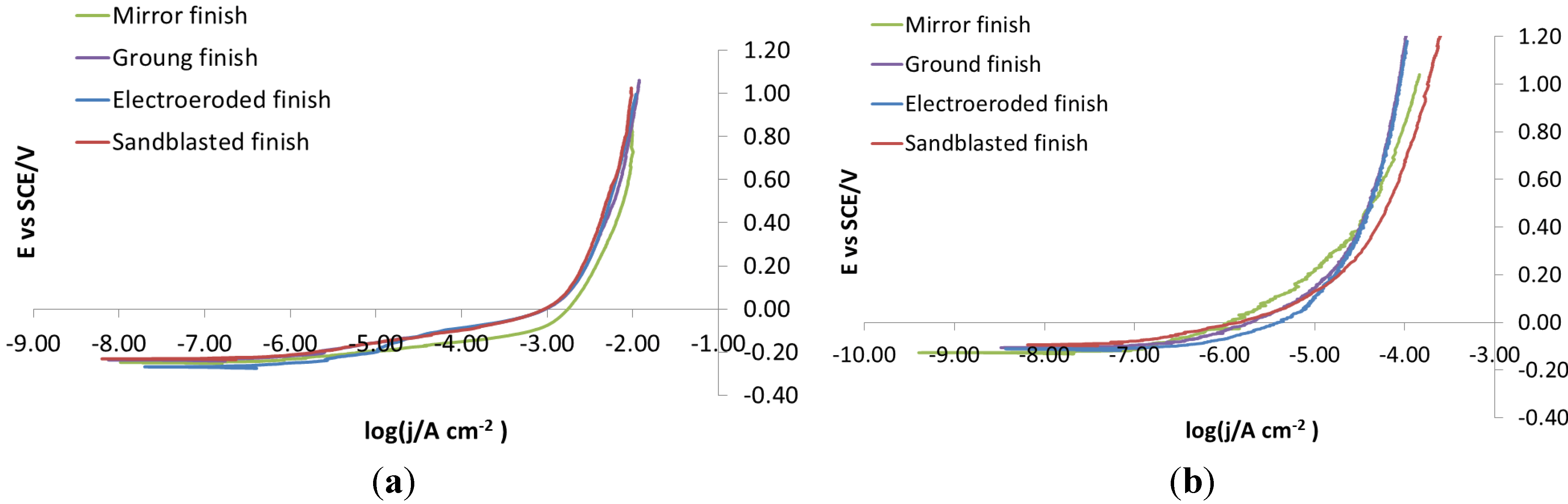
Figure 5a, potentiodynamic polarizations recorded on bare steels on each surface finish in NaCl 0.1 M do not show any difference in the corrosion behavior between the four different surface finishes. This is because the concentration of NaCl was too high, so much that the corrosive attack takes place immediately and extensively. To avoid these problems, potentiodynamic polarization was re-recorded in NaCl 0.001 M, Figure 5b. In this case, the curves show slightly, but definitely different, trends, depending on which surface they were recorded. For this reason, 0.001 M was chosen as the NaCl concentration for carrying out potentiodynamic polarizations.
Figure 5. X105CrCoMo18-2 bare steel: polarization curve on different finishes. (a) NaCl 0.1 M; (b) NaCl 0.001 M.
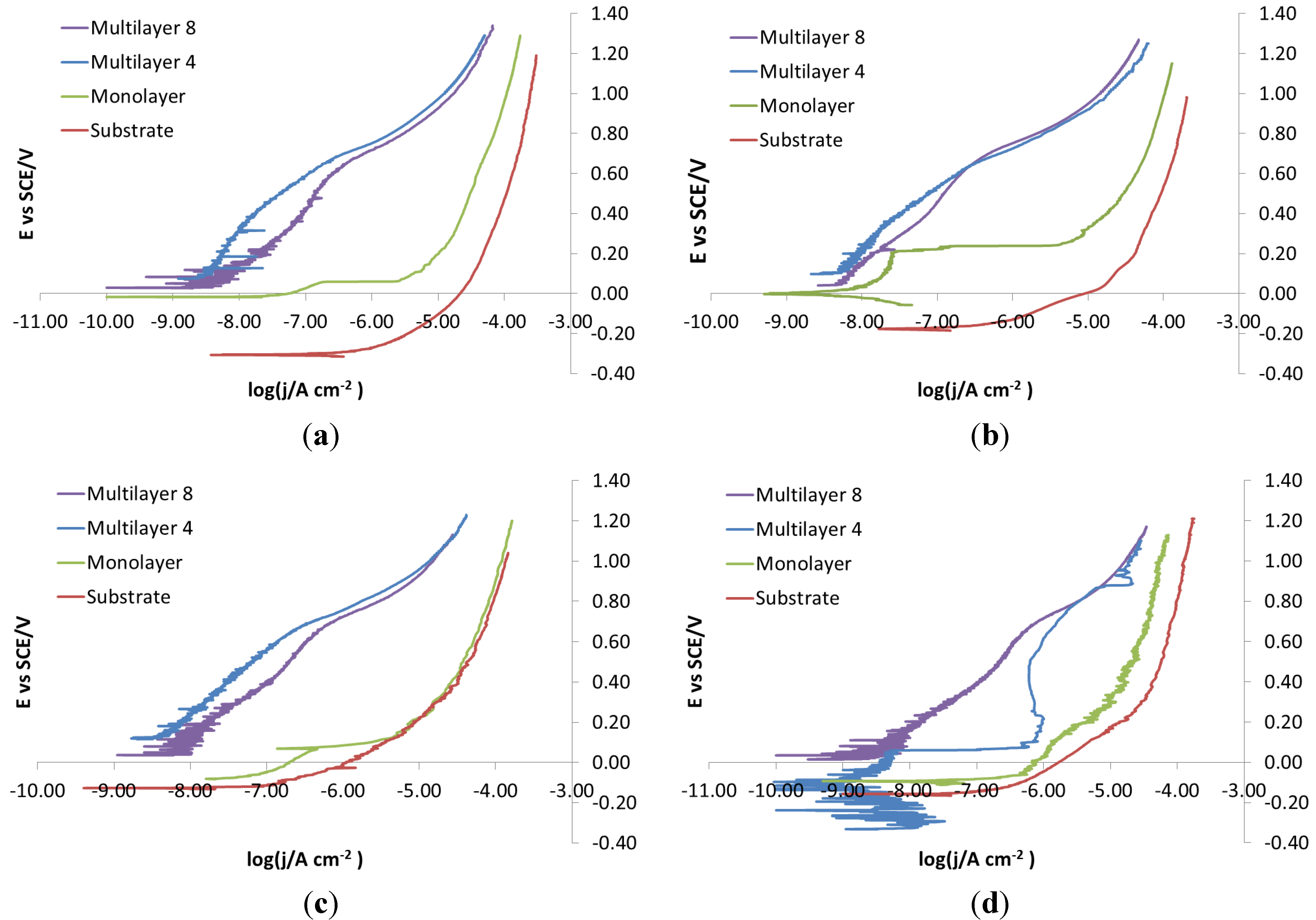
Coatings 04 00508 g005
In 
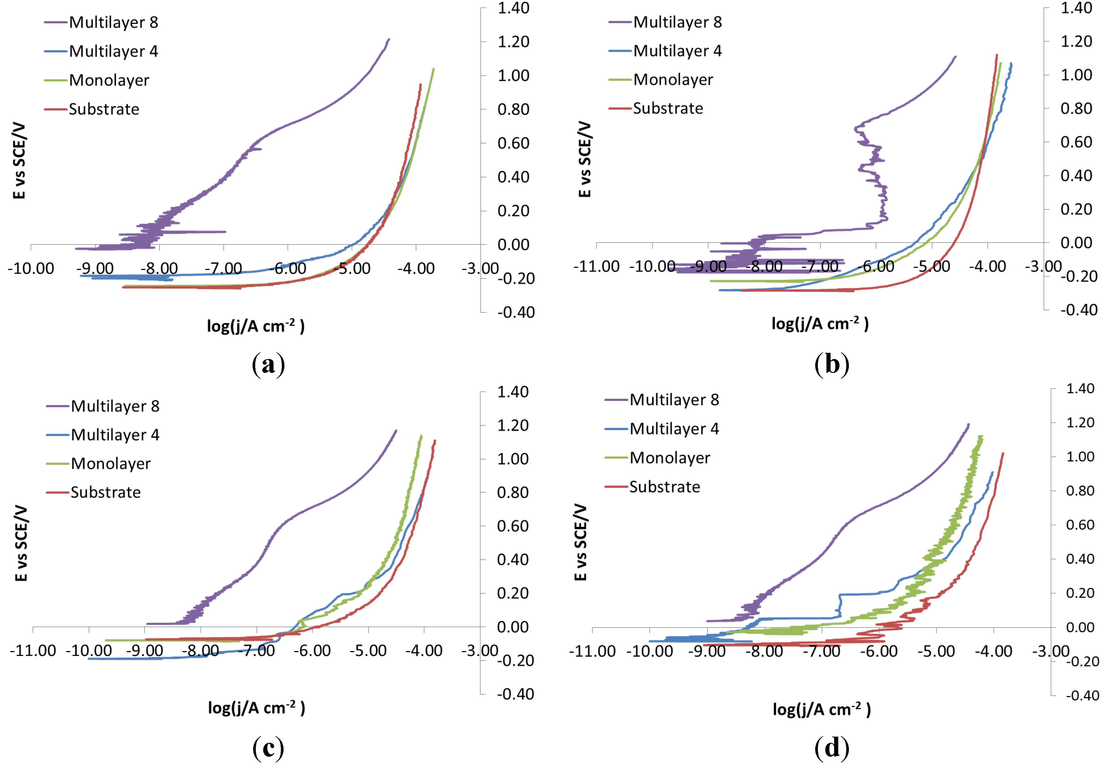
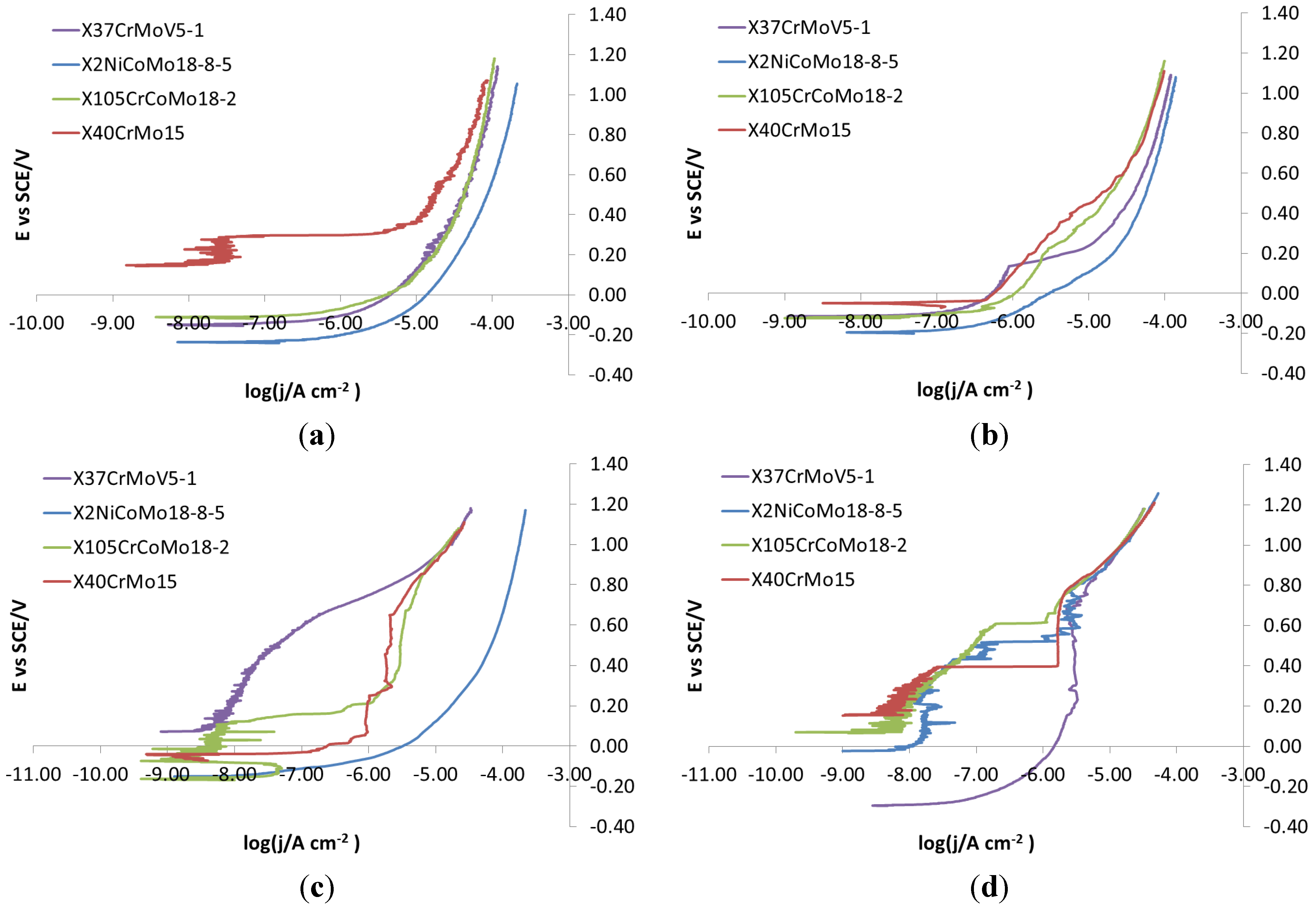
Figure 6, recorded on mirror finish surfaces, the same corrosion behavior for the four bare steels can be noticed. Actually, all steels show active dissolution. The same active behavior is maintained for all steels after the introduction of monolayer coatings. Even if the applied potential is the same, the curves of X37CrMoV5-1 and X2NiCoMo18-8-5 steels move towards lower currents than the curves of X105CrCoMo18-2 and X40CrMo15 steels. The corrosion behavior improves greatly for X37CrMoV5-1, X2NiCoMo18-8-5 and X105CrCoMo18-2 steels with Multilayer 4 coatings, while for X40CrMo15 steel, it appears that corrosive attack takes place after coating breakdown. Finally, the corrosion behavior improves greatly for all steels if Multilayer 8 coatings are applied. The shape of the curves is indicative of a barrier effect that is created against the external environment, which slows down the kinetics of corrosion, putting it under diffusion control.
Figure 6. Mirror finish: polarization curves on bare and coated steels. (a) X37CrMoV5-1; (b) X2NiCoMo18-8-5; (c) X105CrCoMo18-2; (d) X40CrMo15.
Coatings 04 00508 g006
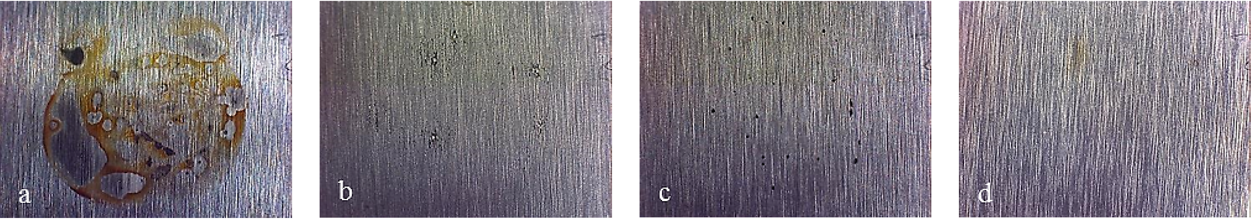
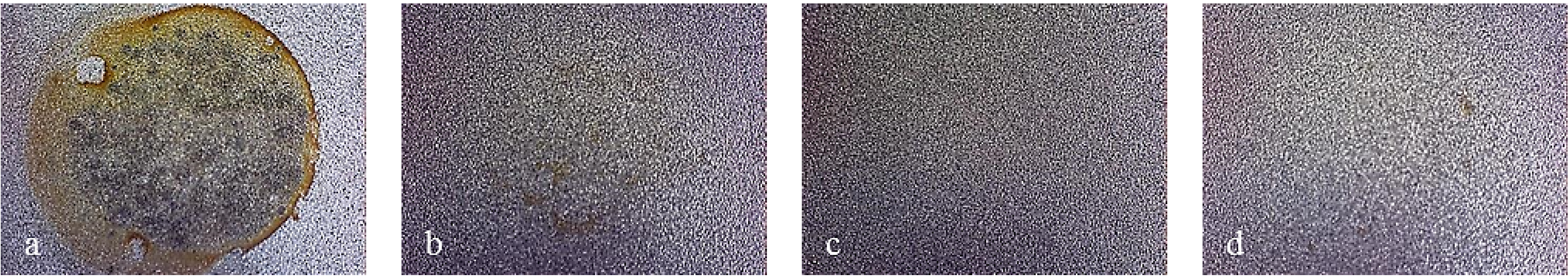
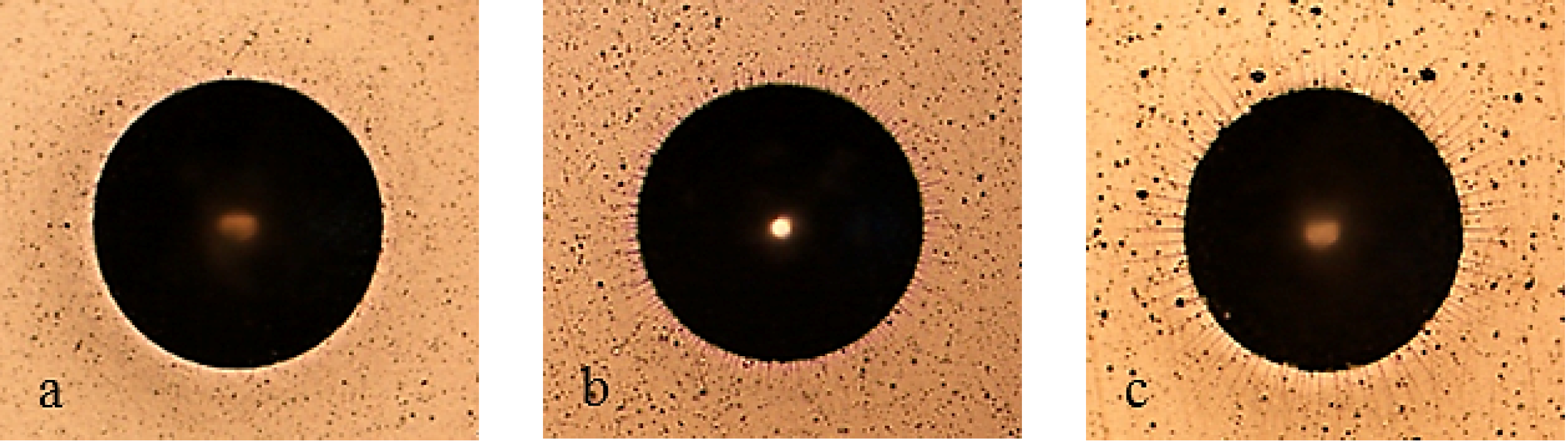
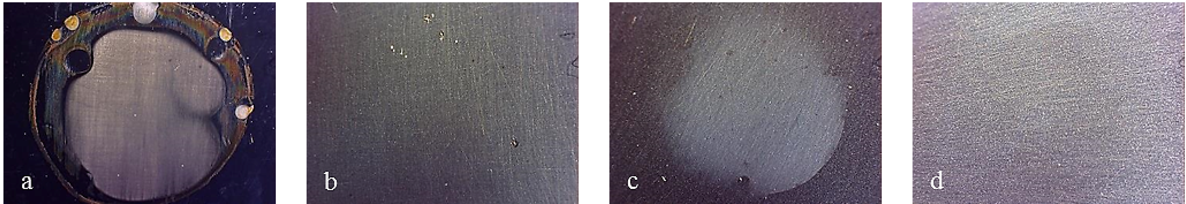
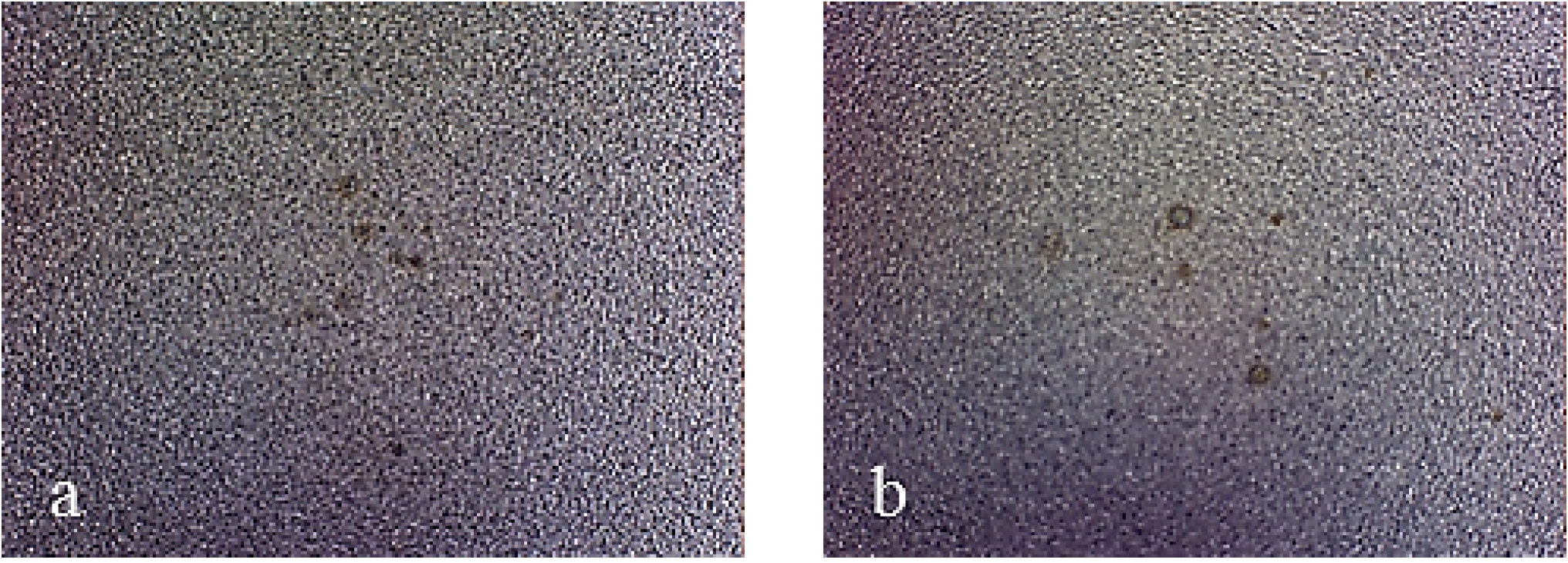
Figure 7 shows pictures of the working area after polarization of mirror finished X2NiCoMo18-8-5 steel. On this picture, uniform corrosion can be noticed on bare steel, while for monolayer-coated steel, corrosion becomes localized. As Multilayer 4 is applied, the result of corrosive attack is the loss of brilliance of the surface, due to the increase in porosity of the coating. Finally, the surface protected with Multilayer 8 does not appear damaged, except for a light loss of brilliance. Figure 8 shows that other bare steels exhibited different corrosion attack, but the coated ones showed the same improvement of surface conditions as for X2NiCoMo18-8-5 coated steel.
Figure 7. Working area after polarization on X2NiCoMO18-8-5 steel, mirror finished. (a) Bare; (b) Monolayer; (c) Multilayer 4; (d) Multilayer 8.
Coatings 04 00508 g007
Figure 8. Working area after polarization on bare mirror finish: (a) X37CrMoV5-1; (b) X105CrCoMo18-2; (c) X40CrMo15.
Coatings 04 00508 g008
In Figure 9, all ground finish steels show the same corrosion behavior. Only the Multilayer 8 coating protects from corrosion. The monolayer and Multilayer 4 coatings, due to the small thickness, are unable to fit the basic finish, thus resulting in being unsuccessful in providing protection.
Figure 9. Ground finish: polarization curves on bare and coated steels. (a) X37CrMoV5-1; (b) X2NiCoMo18-8-5; (c) X105CrCoMo18-2; (d) X40CrMo15.
Coatings 04 00508 g009
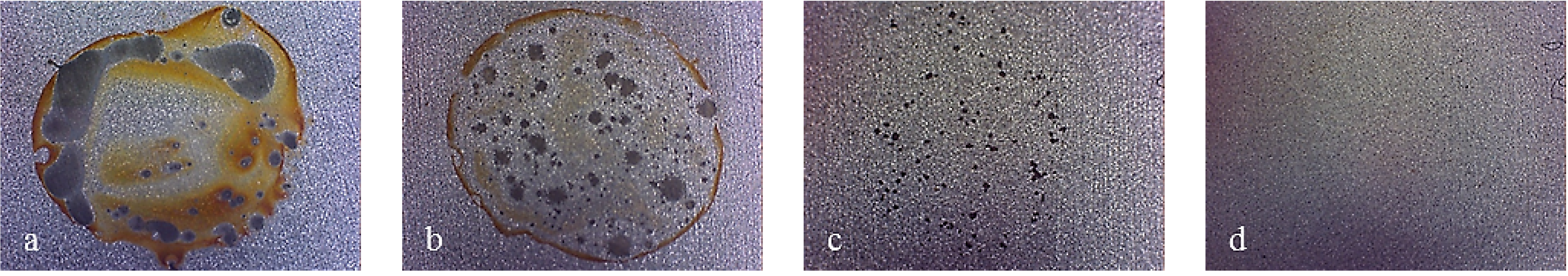
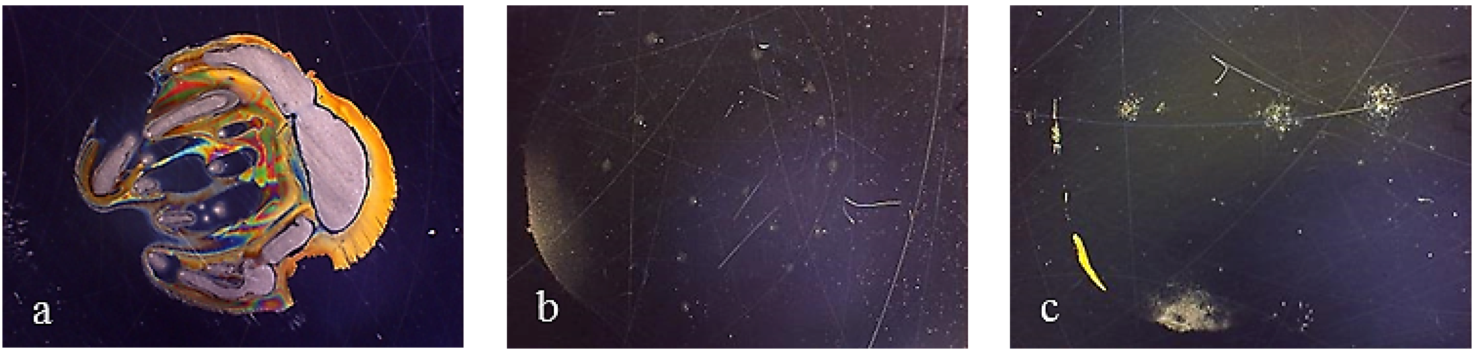
Figure 10 displays the characteristic behavior observed for all ground finish coated samples. In particular, as the number of layers grow, the size of localized attack decreases. As Multilayer 8 is applied, spots of breakdown are no longer visible. Bare steels showed different corrosion attack also in this case (Figure 11).
Figure 10. Working area after polarization on X2NiCoMO18-8-5 steel, ground finished. (a) Bare; (b) monolayer; (c) Multilayer 4; (d) Multilayer 8.
Coatings 04 00508 g010
Figure 11. Working area after polarization on the bare ground finish: (a) X37CrMoV5-1; (b) X105CrCoMo18-2; (c) X40CrMo15.
Coatings 04 00508 g011
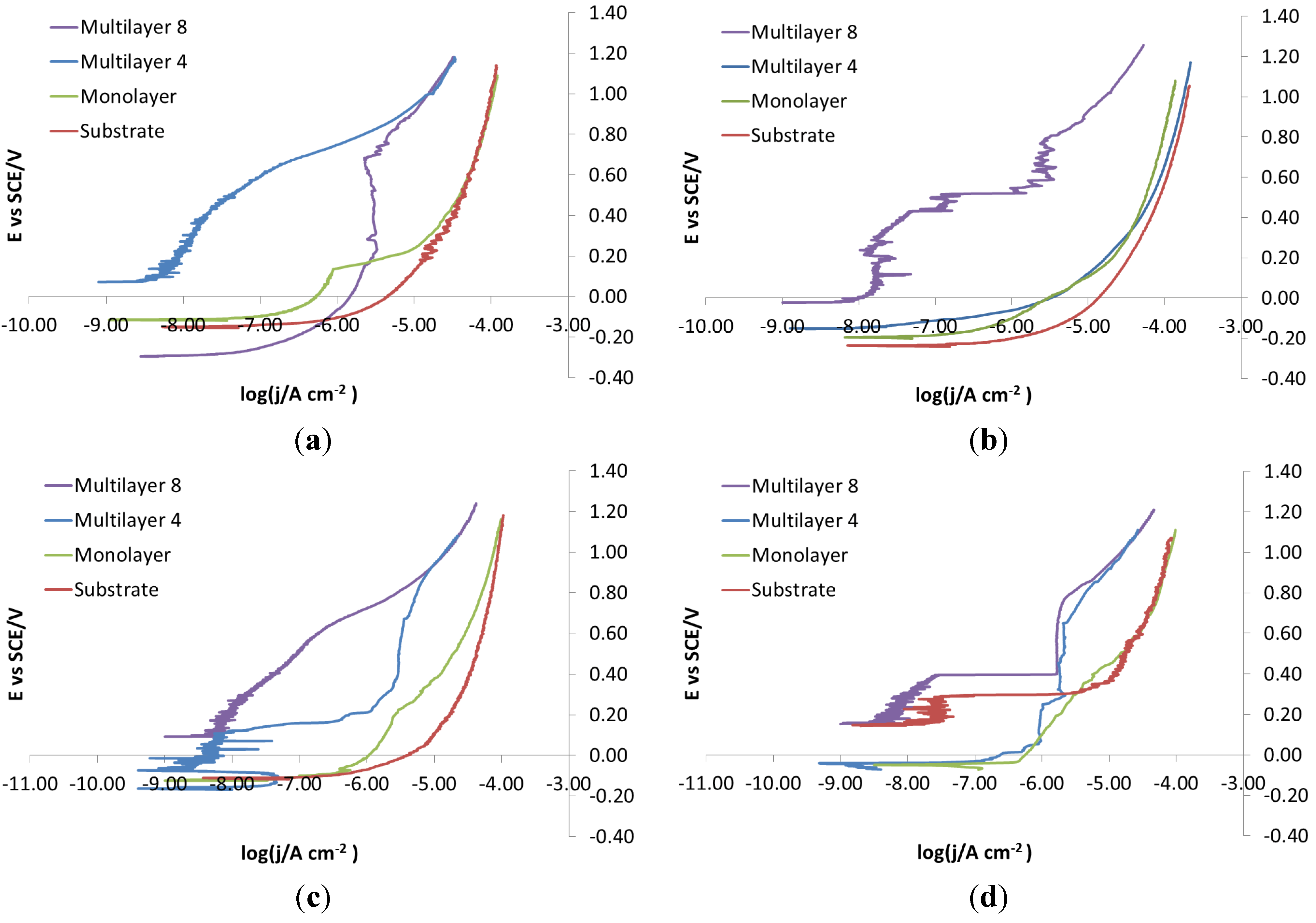
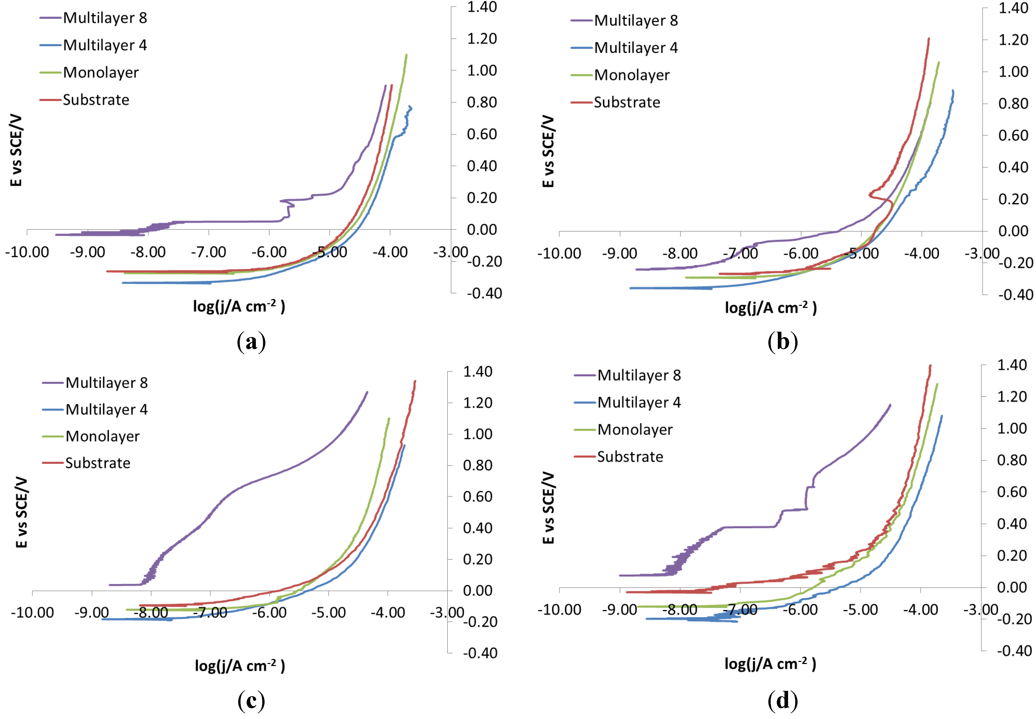
As for the electro-eroded finish (Figure 12), both bare and monolayer-coated steels show active dissolution. On the contrary, for others with coating in the same figure, a difference in the corrosion behavior of X37CrMoV5-1 and X2NiCoMo18-8-5 can be noticed. For X37CrMoV5-1, the corrosion behavior improves greatly with Multilayer 4. As for this coating, thanks to a barrier effect, the shift of the curves towards lower currents, at the same applied potential, can be seen. Multilayer 8 coating shows a passive behavior, characteristic of a superficial chromium layer. The disappearance of the barrier effect with the Multilayer 8 coating can be explained as follows. The increase in thickness causes greater brittleness, because of rising of tensions inside the coating, plus tensions accumulated in the steel during electro-erosion. On the contrary, for X2NiCoMo18-8-5, Multilayer 4 does not provide protection against corrosion, which is effectively provided by the Multilayer 8 coating. The absence of brittleness in the coating with the maximum thickness is due to the capacity of X2NiCoMo18-8-5 to relax tensions accumulated during electro-erosion.
In 
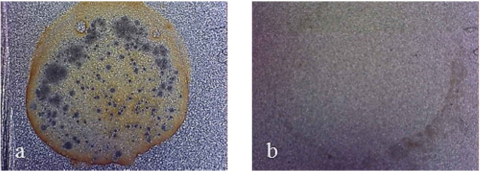
Figure 13, it can be noticed that as Multilayer 8 is applied on X37CrMoV5-1 steel, there is a worsening of corrosive attack with respect to Multilayer 4.
Figure 14 shows that the morphology of the corrosive attack of X40CrMo15 is related to the electrochemical behavior reported in Figure 12, since there is a worsening of the corrosive attack from bare steels to Multilayer 4. Only with Multilayer 8 are the spots of breakdown no longer visible.
In Figure 15, it is seen that for X2NiCoMo18-8-5 steel with a growing number of layers, the corrosive attack decreases. The same corrosive attack was observed for X105CrCoMo18-2 coated steel.
Figure 12. Electro-eroded finish: polarization curves on bare and coated steels. (a) X37CrMoV5-1; (b) X2NiCoMo18-8-5; (c) X105CrCoMo18-2; (d) X40CrMo15.
Coatings 04 00508 g012
Figure 13. Working area after polarization on X37CrMoV5-1 steel, electro-eroded finish. (a) Multilayer 4; (b) Multilayer 8.
Coatings 04 00508 g013
Figure 14. Working area after polarization on X40CrMo15 steel, sandblasted finish. (a) Bare; (b) Monolayer; (c) Multilayer 4; (d) Multilayer 8.
Coatings 04 00508 g014
Figure 15. Working area after polarization on X2NiCoMo18-8-5 steel, sandblasted finish. (a) Bare; (b) Monolayer; (c) Multilayer 4; (d) Multilayer 8.
Coatings 04 00508 g015
In Figure 16, on a sandblasted finish, monolayer and Multilayer 4 coatings are seen not to provide any protection against corrosion for all steels. In some cases, as these coatings are applied, worse performance than for bare steels is even observed. For X37CrMoV5-1, X2NiCoMo18-8-5 and X40CrMo15 steels, the corrosion behavior does not improve significantly, even as the Multilayer 8 coating is applied. On the contrary, X105CrCoMo18-2 steel coated with Multilayer 8 shows great improvements in the corrosion behavior.
Figure 16. Sandblasted finish: polarization curves on bare and coated steels. (a) X37CrMoV5-1; (b) X2NiCoMo18-8-5; (c) X105CrCoMo18-2; (d) X40CrMo15.
Coatings 04 00508 g016
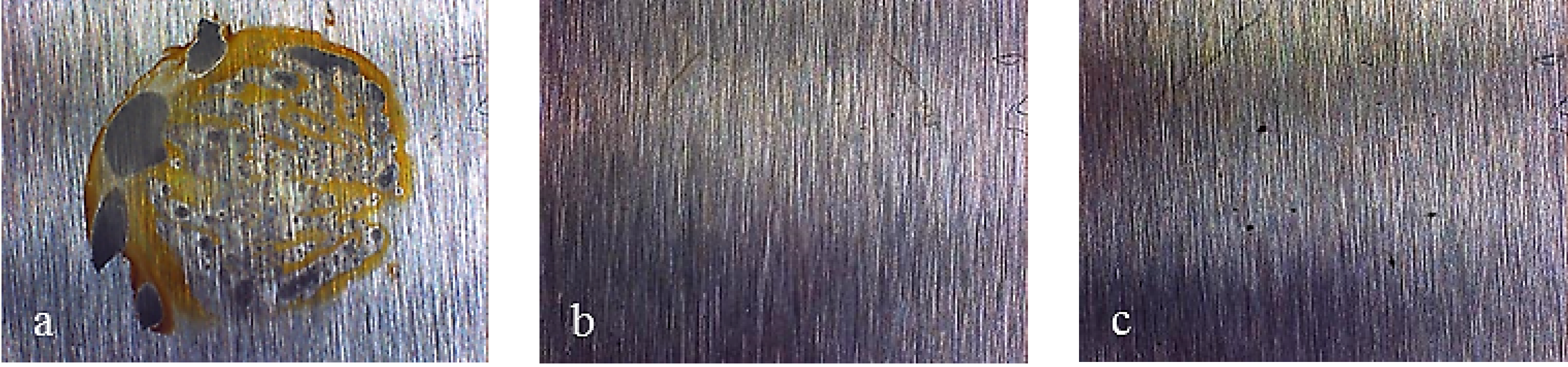
Figure 17 displays the behavior observed with X37CrMoV5-1 sandblasted finish samples. In particular, it is noticed that the bare steel shows uniform corrosion that becomes localized once the monolayer is applied. Furthermore, as the number of layers grows, the extent of localized attack decreases. As Multilayer 8 is applied, spots of breakdown were no longer visible. X2NiCoMo18-8-5 and X105CrCoMo18-2 bare steels showed different corrosion attack, but the coated ones showed the same improvement of the surface condition as that seen for X37CrMoV5-1 coated steel (Figure 18).
Figure 17. Working area after polarization on X37CrMoV5-1 steel, sandblasted finished. (a) Bare; (b) Monolayer; (c) Multilayer 4; (d) Multilayer 8.
Coatings 04 00508 g017
Figure 18. Working area after polarization on bare sandblasted finish: (a) X2NiCoMo18-8-5; (b) X105CrCoMo18-2.
Coatings 04 00508 g018
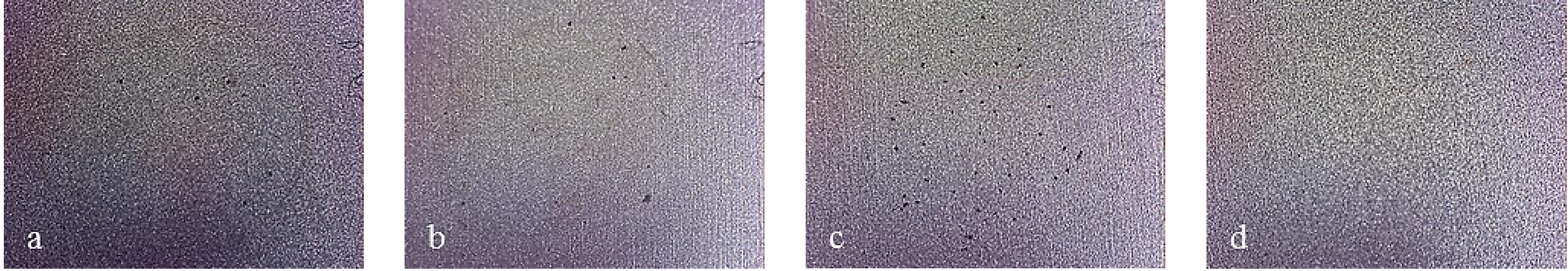
Figure 19 shows that the morphology of corrosive attack of X40CrMo15 corresponds to the electrochemical behavior reported in Figure 16. Actually, worsening of corrosive attack is observed from bare steels to Multilayer 4. Only as Multilayer 8 is applied do spots of breakdown become no longer visible.
Figure 19. Working area after polarization on X40CrMo15 steel, sandblasted finish. (a) Bare; (b) Monolayer; (c) Multilayer 4; (d) Multilayer 8.
Coatings 04 00508 g019
Figure 20 displays curves showing the effect of substrate steel with an electro-eroded finish. The corrosion behavior of X105CrCoMo18-2 and X2NiCoMo18-8-5 steels can be readily explained by the fact that only coatings as thick as Multilayer 8 can provide a homogeneous surface without cracks and pinholes that acts as a barrier. On the contrary, X37CrMoV5-1 steel protected with coatings at intermediate thickness, such as Multilayer 4, shows better corrosion behavior than with Multilayer 8. Finally, the behavior of X40CrMo15 is very particular. As shown in Figure 20, the curves recorded for bare steel show a tentative passivation and a shift to higher potential than curves for steel coated with a monolayer and Multilayer 4. With Multilayer 8, finally, the barrier effect of the coating can be observed.
Figure 20. Electro-eroded finish: polarization curves on different steels. (a) Bare; (b) Monolayer; (c) Multilayer 4; (d) Multilayer 8.
Coatings 04 00508 g020

3.7. SEM Analysis

SEM pictures of X37CrMoV5-1 steel are presented in 
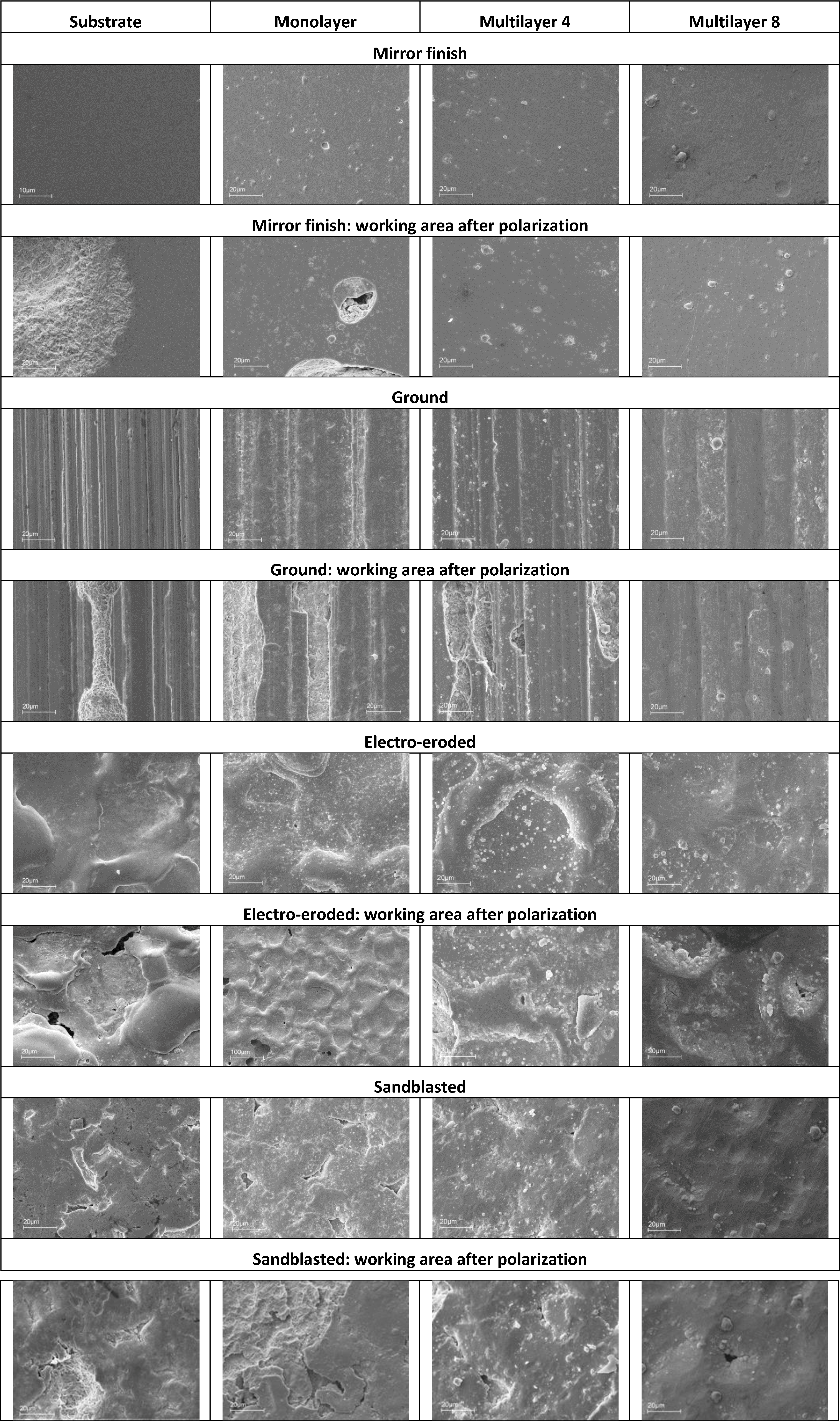
Figure 21. The coatings applied on the mirror finish show a homogeneous surface and less defects, with the exception of the presence of droplets. From the working areas of the monolayer, it can be noticed that corrosive attack and breakdown of the coating take place next to the droplets. The working areas of Multilayers 4 and 8 are practically intact, but there is an increase of porosity in the regions next to the droplets.
Figure 21. SEM images of X37CrMoV5-1 sample surfaces of different finished and coatings before and after polarization.
Coatings 04 00508 g021
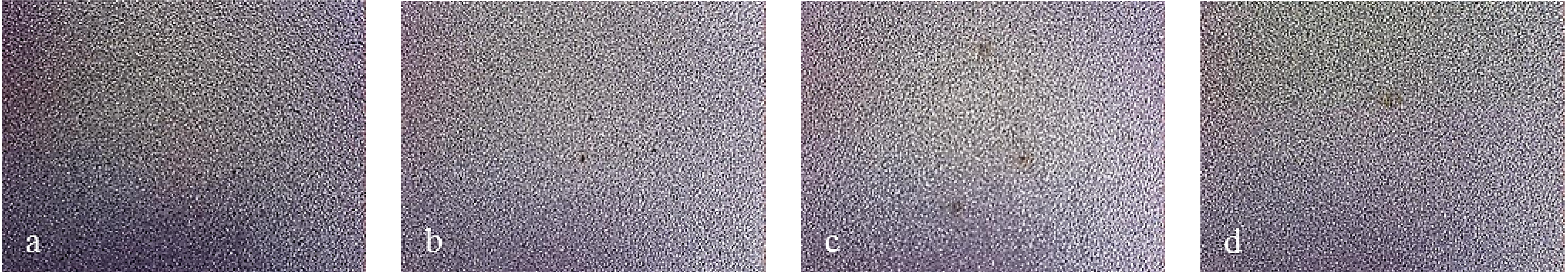
As for the ground finish substrate, the corrosive attack follows the grinding crests and spreads as generalized corrosion. As for coatings on such a finish, it is noticed that the droplets are located on the grinding crests. The same corrosion behavior of the substrate is observed for the monolayer and Multilayer 4. Multilayer 8 shows localized corrosion, which does not depend on the morphology of the ground lines. For coated samples of electro-eroded finish surfaces, the concentration of droplets is greater in the areas between crests and depressions, while it is lower on the crest top. The working surface of the substrate shows localized corrosion in the regions between crests and depressions, where the white layer is smaller, as seen after the metallographic analysis. As for the monolayer and Multilayer 4, corrosion attack and the resulting coating breakdown are located in the same critical areas of the substrate. Multilayer 8 shows a surface characterized by the presence of cracks. The surface of the sandblasted finish substrate shows a great number of sharp holes and crests, which cannot be covered by the monolayer and Multilayer 4. The substrate working surface shows that localized corrosion tends to be widespread. This takes place next to the holes of the surface. As for the monolayer and Multilayer 4, corrosion attack and the resulting coating breakdown are localized in the same critical areas already observed in the substrate. Multilayer 8 shows localized corrosion attack as lighter compared to the previous coatings applied on this finish [8].
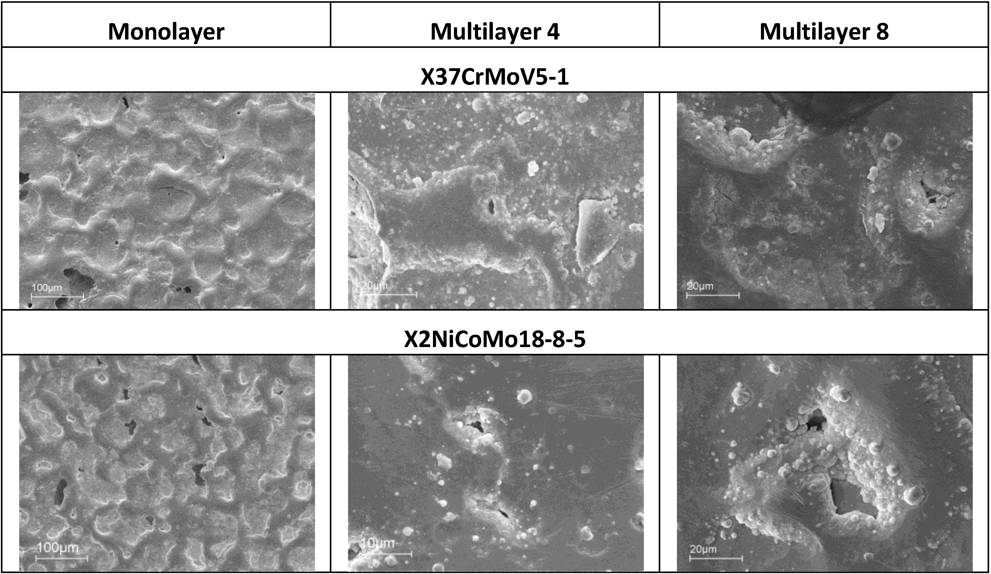
SEM analysis can help to understand differences in the corrosion observed during electrochemical characterization. For example, if electro-eroded surfaces are compared after polarization of X37CrMoV5-1 and X2NiCoMo18-8-5 steels, it is noticed that the surface of the Multilayer 8 coating on X37CrMoV5-1 steel is richer in cracks than the same coating on X2NiCoMo18-8-5 steel. That can explain why the polarization curves of X2NiCoMo18-8-5 coated with Multilayer 8 show a barrier effect, while the same polarization recorded on X37CrMoV5-1 coated with the same Multilayer 8 gives curves shifted to higher currents without the barrier effect (Figure 12). The situation is different for these two steels with the Multilayer 4 coating, since with this coating, X37CrMoV5-1 steel shows a surface with a few spots of breakdown, while for X2NiVoMo18-8-5 steel, the number and extent of breakdown is higher. It is this difference that can explain why curves recorded on Multilayer 4-coated X37CrMoV5-1 steel shows a barrier effect, whereas the same polarization on X2NiCoMo18-8-5 coated with the same Multilayer 4 gives curves indicating the absence of protective actions (Figure 12). Finally, Figure 22 shows that both surfaces of X37CrMoV5-1 and X2NiCoMo18-8-5 steels coated with monolayers are extremely damaged. Accordingly, the respective polarization curves (Figure 12) show the same active behavior typically of the absence of protection.
Figure 22. SEM images of X37CrMoV5-1 and X2NiCoMo18-8-5 electro-eroded surfaces after polarization.
Coatings 04 00508 g022

4. Conclusions

The anticorrosive properties of coatings improve with increasing thickness more definitely if a multilayer structure is introduced. Two factors have however to be considered as being closely linked: (i) surface finish; as well as (ii) the nature of the underlying material (substrate). In particular, for the mirror finish without defects, as well as for the ground finish, the corrosion behavior depends essentially on the surface finish. Actually, all steels show barrier effects in the former case (mirror), since coatings can easily cover the underlying material uniformly, thus preventing aggressive media from penetrating the protective layer. In the latter case (ground), only Multilayer 8 coatings protect the substrate efficiently, whereas other lower thickness coatings do not follow the finishing profile of the underlying surface, thus leaving uncovered spots where corrosion can develop.
The situation turns out different with electro-eroded and sandblasted finishes, in that the corrosion behavior appears to depend on the nature of the substrate more than on the surface finish. Thus, in the former case (electro-eroded), Multilayer 8 coatings are more effective with steels capable of relaxing tensions, such as X2NiCoMo18-8-5. For tensioned steels, e.g., X37CrMoV5-1, a compromise has to be found by applying Multilayer 4 coatings characterized by a lower tension than Multilayer 8. In the latter case (sandblasted), the corrosion behavior appears to depend on the hardness of the substrate. In particular, corrosion is more severe with the monolayer, as well as Multilayer 4 coatings. However, as noticed with X105CrCoMo18-2, in particular, the corrosion behavior improves more the harder the (steel) substrate.

Author Contributions

Fabio Cova Caiazzo: experimental work in the Department of Chemistry, Milan. Valentina Sisti: experimental work at CRT Company, Nerviano. Stefano P. Trasatti: group leader, research idea, general supervision, paper drafting. Sergio Trasatti: scientific coordination, experimental data analysis, contribution to paper drafting.

Conflicts of Interest

The authors declare no conflict of interest.

References

  1. Vetter, J. Vacuum arc coatings for tools: Potential and application. Surf. Coat. Technol. 1995, 76–77, 719–724. [Google Scholar] [CrossRef]
  2. Wang, H.W.; Stack, M.M.; Lyons, S.B.; Hovsepian, P.; Münz, W.D. The corrosion behaviour of macroparticle defects in arc bond-sputtered CrN/NbN superlattice coatings. Surf. Coat. Technol. 2000, 126, 279–287. [Google Scholar] [CrossRef]
  3. Song, G.H.; Yang, X.P.; Xiong, G.L.; Lou, L.; Chen, L.J. The corrosive behavior of Cr/CrN multilayer coatings with different modulation periods. Vacuum 2013, 89, 136–141. [Google Scholar] [CrossRef]
  4. Amorim, F.L.; Weingaertner, W.R. Die-sinking electrical discharge machining of a high-strength copper-based alloy for injection molds. J. Braz. Soc. Mech. Sci. Eng. 2004, 26, 137–144. [Google Scholar]
  5. Bayón, R.; Igartua, A.; Fernández, X.; Martínez, R.; Rodríguez, R.J.; García, J.A.; de Frutos, A.; Arenas, M.A.; de Damborenea, J. Corrosion-wear behaviour of PVD Cr/CrN multilayer coatings for gear application. Tribol. Int. 2009, 42, 591–599. [Google Scholar] [CrossRef]
  6. Grips, V.K.W.; Selvi, V.E.; Barshilia, H.C.; Rajam, K.S. Electrochemical behavior of single layer CrN, TiN, TiAlN coatings and nanolayered TiAlN/CrN multilayer coatings prepared by reactive direct current magnetron sputtering. Electrochim. Acta 2006, 51, 3461–3468. [Google Scholar] [CrossRef]
  7. Monticelli, C.; Balbo, A.; Zucchi, F. Corrosion and tribocorrosion behaviour of cermet and cermet/nanoscale multilayer CrN/NbN coatings. Surf. Coat. Technol. 2010, 204, 1452–1460. [Google Scholar] [CrossRef]
  8. Caiazzo, C.F.; Trasatti, S.P.; Sisti, V. Multilayer coatings based on CrN/Cr for molds of plastics. Metall. Ital. 2014, 106, 3–8. [Google Scholar]
  9. Van der Kolk, J.; Strondl, C.; Tietema, R.; Lewis, D.; Hurkmans, T. Surface coatings for superior gears. SAE Tech. Paper 2004. [Google Scholar] [CrossRef]

