Article

Interfacial Effects and Wetting–Drying Cycle Damage Inhibition of Coastal Saline Soil Modified by Xanthan Gum Biopolymer Coating

1
School of Intelligent Construction, Fuzhou University of International Studies and Trade, Fuzhou 350202, China
2
College of Metropolitan Transportation, Beijing University of Technology, Beijing 100124, China
3
Hongyuan Waterproof Technology Group Co., Ltd., Weifang 261000, China
*
Author to whom correspondence should be addressed.
Coatings 2026, 16(9), 1107; https://doi.org/10.3390/coatings16091107
Submission received: 23 July 2026 / Revised: 10 September 2026 / Accepted: 11 September 2026 / Published: 17 September 2026

Abstract

Coastal saline soils are vulnerable to degradation under repeated wetting–drying (W–D) exposure, while conventional inorganic stabilizers are associated with high energy consumption and environmental burdens. To address this issue, an environmentally friendly ternary stabilization system consisting of local sandy silt, low-dose cement, and xanthan gum (XG) at different dosages was developed, with emphasis on the particle-scale coating effect of hydrated XG. Accelerated laboratory W–D cycling (0–20 cycles), direct shear tests, unconfined compressive strength (UCS) tests, binary-image crack analysis, and field-emission scanning electron microscopy (FE-SEM) were used to evaluate the effects of W–D cycling and XG dosage (0%–2.0%) on mechanical properties, interfacial bonding, surface deterioration, and microstructural evolution. An optimum XG dosage of 1.5% was identified. Before W–D cycling, the UCS of the 1.5% XG group reached 1005.4 kPa, 94.9% higher than that of the 0% XG control. After 20 W–D cycles, the 1.5% XG group exhibited a mass loss rate of 3.7%, a crack ratio below 4.3%, and a compressive strength retention of 83.8%, whereas the 0% XG control showed more pronounced mass loss and strength degradation. The XG coating limited water and salt migration and provided flexible interparticle bridging that mitigated shrinkage-induced stress concentration. FE-SEM observations further indicated that XG and cement hydration products formed a relatively continuous organic–inorganic interfacial network, which helped preserve particle contacts and restrain microcrack propagation during cyclic exposure. These results demonstrate the potential of particle-scale XG coating for improving the W–D durability of modified saline soil.

1. Introduction

Coastal saline soils are widely distributed across coastal zones and coastal alluvial plains, particularly in arid and semiarid regions. With the continued expansion of transportation infrastructure in coastal areas, highways, railways, and ports increasingly traverse saline-soil deposits. Coastal saline soils commonly exhibit high natural water content, poor particle-size gradation, strong hydrophilicity, and elevated concentrations of soluble salts such as chlorides and sulfates [1]. Periodic groundwater fluctuations and seasonal rainfall–evaporation cycles subject saline soils to repeated wetting and drying, which can progressively degrade their mechanical performance [2]. The associated redistribution of moisture and soluble salts may induce shrinkage–swelling, salt crystallization, and strength degradation, thereby increasing the risk of subgrade deformation and pavement distress [3,4].
Conventional stabilization of soft and saline subgrades commonly relies on relatively high dosages of inorganic binders (cement, lime, fly ash, etc.). Although such materials can effectively improve the early strength of the soil, their use has several limitations: firstly, the production of conventional inorganic binders is energy-intensive and associated with substantial carbon emissions [5]; secondly, the addition of high-dosage inorganic stabilizers may alter the chemical environment and hydration characteristics of saline soils, thereby affecting the long-term stability and service performance of the modified soil under complex environmental conditions [6]; thirdly, under severe wetting–drying (W–D) conditions, rigid cemented matrices are prone to brittle fracture and durability deterioration [7]. Existing studies have mainly treated biopolymers as bulk soil-binding agents, with comparatively less attention paid to their role as particle-surface coatings in regulating interfacial bonding and damage evolution, whereas interfacial behavior plays an important role in determining the mechanical properties and durability of modified soil. Therefore, developing a green, low-carbon, eco-friendly interfacial modification technology for saline soil stabilization with improved durability under W–D cycling represents an important scientific and technical challenge in transportation infrastructure and sustainable geotechnical engineering.
In recent years, bio-based reinforcement materials, particularly biopolymers, have received considerable attention in geotechnical reinforcement, sand stabilization, and ecological restoration because of their favorable rheological properties, strong particle-bonding capacity, and biodegradability [8,9,10]. Numerous studies have investigated the stabilization mechanisms and macroscopic performance of biopolymer-treated soils. In terms of biomaterial selection and basic mechanical property enhancement, xanthan gum (XG), a high-molecular-weight extracellular polysaccharide produced by the fermentation of Xanthomonas campestris, has emerged as a promising soil-modification material [11]. Upon hydration, XG rapidly develops into a highly viscous pseudoplastic hydrogel. The carboxyl and hydroxyl groups along its molecular chains interact with cations on soil-particle surfaces through hydrogen bonding, van der Waals forces, and electrostatic attraction. These interactions strengthen particle adsorption and bridging, thereby improving the unconfined compressive and shear strengths of sands, silts, and soft clays [12,13]. From an interfacial modification perspective, hydrated XG can form a relatively continuous gel layer on soil-particle surfaces, producing a particle-scale coating effect. This interfacial layer modifies particle contacts and bonding conditions and, in turn, influences the durability response of the treated soil under cyclic environmental loading.
Recent studies on saline and expansive soils have further shown that appropriate XG dosages can form interconnected networks between soil particles while restricting the migration of free salt ions through gel encapsulation, thereby reducing drying–shrinkage and wetting–swelling deformation [14]. Recent studies on the durability of biopolymer-stabilized soils have examined their deterioration under cyclic environmental conditions such as freeze–thaw and W–D cycling. These studies indicate that capillary shrinkage stresses generated during W–D cycling can induce fatigue damage in conventional cemented soil structures, whereas an appropriate XG dosage can accommodate deformation through a flexible cross-linked network and slow strength degradation within a certain number of cycles [15,16].
Although existing studies on XG-modified soils have provided valuable insights into their stabilization mechanisms and engineering performance [17], several knowledge gaps and engineering limitations remain regarding the long-term W–D durability of coastal saline soils. First, much of the existing literature focuses on pure fine sand, kaolin, or artificially prepared saline soil, whereas targeted studies on natural coastal saline soils, particularly high-chloride soils with poor particle-size gradation, high soluble-salt contents, and complex mineral compositions, remain limited. Second, the combined effects of stabilization systems and environmental conditions have not been fully addressed. Single-XG stabilization systems may exhibit limited water stability because of the strong hydrophilicity of XG. Under prolonged immersion or repeated W–D cycling, pure polysaccharide hydrogels may undergo excessive water uptake, swelling, and leaching. Accordingly, the synergistic mechanism of a low-dose cement skeleton combined with flexible XG interfacial bonding has not yet been fully elucidated [18]. Moreover, fatigue-induced microdamage and crack evolution at the two key interfaces—the coating–soil particle interface and the coating–cement hydration product interface—remain insufficiently understood under cyclic environmental exposure. Existing W–D studies have mainly focused on changes in macroscopic mechanical properties, such as unconfined compressive strength (UCS). However, systematic quantitative analysis of interfacial damage initiation and propagation in modified soil under the combined effects of repeated moisture infiltration–evaporation, salt migration, and stress variation remains insufficient. Meanwhile, the microstructural evolution and damage mechanisms of the composite interface formed by cement hydration products and XG organic gel during W–D cycles have not been fully elucidated, and high-resolution SEM investigations of this interfacial evolution remain limited. Therefore, it is necessary to investigate the durability enhancement mechanism of XG-modified coastal saline soil from multiple perspectives, including macroscopic mechanical responses, surface damage evolution, and microscopic interfacial structure changes.
To address these gaps, this study investigates a typical poorly graded coastal saline soil from the Weifang area of Bohai Bay using a ternary composite stabilization system consisting of local sandy silt for particle-gradation adjustment, low-dose cement for rigid skeletal bonding, and XG for particle-scale surface coating. Accelerated laboratory W–D cycling (0–20 cycles), direct shear tests, unconfined compressive strength (UCS) tests, binary-image crack analysis, and field-emission scanning electron microscopy (FE-SEM) were used to evaluate the effects of W–D cycling and XG dosage (0%–2.0%) on shear strength, compressive strength, mass loss, surface cracking, and interfacial microstructure. The analysis focuses on linking macroscopic deterioration with particle-scale interfacial evolution to clarify the role of XG coating in improving the W–D durability of modified saline soil.

2. Materials and Methods

2.1. Materials and Pretreatment

2.1.1. Materials

The materials used in this study consisted of coastal saline soil, sandy silt, ordinary Portland cement, and XG. The saline soil served as the primary soil material, sandy silt was used to improve particle-size gradation, cement was used as the inorganic binder, and XG was used as the biopolymer modifier in the composite stabilization system. The sources and basic properties of these materials are described below.
Saline soil: The saline soil was collected at multiple depths within the 0–2 m subsurface interval in the coastal area of Weifang, Shandong. Prior to laboratory testing, the soil samples collected from different depths were combined and thoroughly mixed to reduce variations associated with sampling depth and to ensure consistency of the soil used for specimen preparation. The homogenized saline soil was considered representative of the overall characteristics of the sampled 0–2 m interval. It was then naturally air-dried, gently crushed using a rubber mortar, passed through a 2 mm standard sieve to remove coarse particles and impurities, and sealed for subsequent testing.
Cement: P·O 42.5-grade ordinary Portland cement (Shandong Weizhou Cement Technology Co., Ltd., Weifang, China) meeting the requirements of Common Portland Cement (GB 175–2023) was selected, with a fixed dosage of 3% throughout the test; the dosages of all cementing materials and admixtures were calculated based on the total dry mass of the 70:30 soil mixture described below. The cement content was selected as a basic stabilizing component to provide initial cementitious bonding for the saline soil matrix while maintaining a relatively low cement dosage, thereby allowing the contribution of XG coating to the mechanical properties and W–D durability of the modified saline soil to be evaluated more clearly.
Sandy silt: The sandy silt was collected from a local non-salinized area in Weifang and used to adjust the particle-size gradation of the saline soil. After natural air-drying, the soil sample was passed through a 2 mm standard sieve, and its particle-size gradation and basic physical properties were measured prior to the test.
XG: XG (Deosen Biochemical (Ordos) Ltd., Ordos, China) was used as the biopolymer modification material. The XG was an off-white fine powder, with 100% passing the 80-mesh sieve and at least 92% passing the 200-mesh sieve. At 25 °C, the apparent viscosity of a 1% XG solution in 1% KCl solution was 1200–1600 mPa·s, and the pH of a 1% aqueous solution was 6.0–8.0. The pore solution of saline soil contains soluble ions such as Na+, Ca2+, Mg2+, Cl, and SO42− at appreciable concentrations. Considering the pronounced salinity of the soil used in this study, its total soluble-salt content and major-ion composition were quantitatively characterized to support the subsequent analyses of mechanical behavior, wetting–drying durability, and microstructure.
The basic physical properties of both the saline soil and sandy silt were systematically determined according to the Test Methods of Soils for Highway Engineering (JTG 3430–2020), and the results are shown in Table 1.
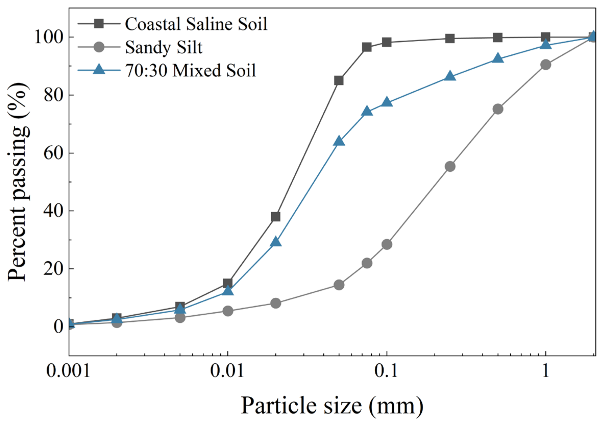
In the subsequent tests, the coastal saline soil and sandy silt were uniformly mixed at a dry mass ratio of 70:30 to prepare the mixed soil, hereafter referred to as the 70:30 mixed soil. This mixing ratio was selected to improve the particle-size gradation of the original coastal saline soil and optimize the particle skeleton structure, providing a relatively stable soil matrix for subsequent modification tests. According to the Test Methods of Soils for Highway Engineering (JTG 3430–2020), the particle-size distributions of the coastal saline soil, sandy silt, and 70:30 mixed soil were determined using the hydrometer method. The particle-size distribution curves are shown in Figure 1, and the corresponding characteristic gradation parameters are summarized in Table 2.
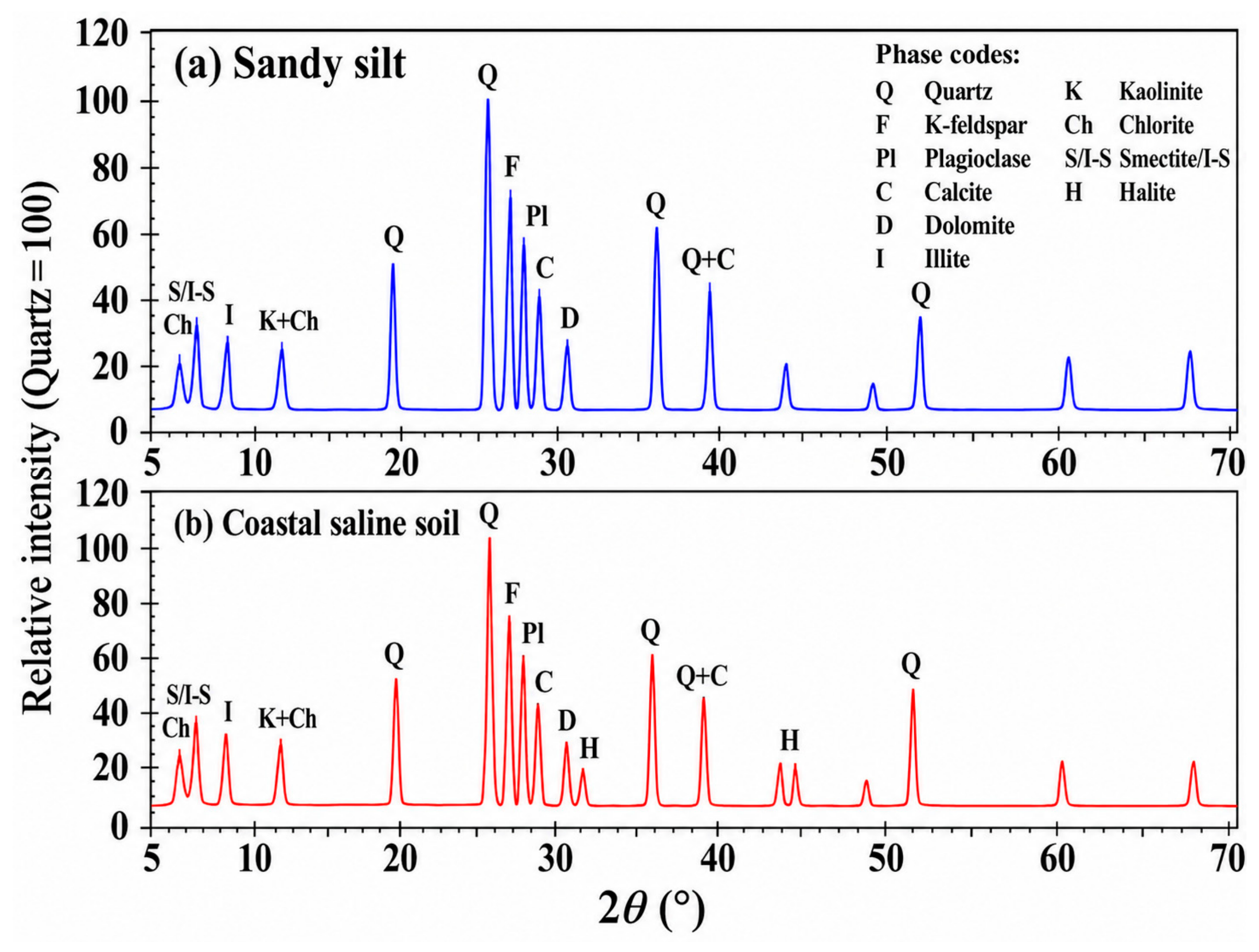
The mineralogical compositions of the coastal saline soil and sandy silt were further characterized by X-ray diffraction (XRD). Representative portions of the two raw soils before the addition of cement and XG were naturally air-dried, gently ground using an agate mortar, and passed through a 75 μm sieve. The prepared powder samples were placed in sample holders and leveled to obtain randomly oriented specimens. XRD measurements were performed using an Empyrean X-ray diffractometer (Malvern Panalytical B.V., Almelo, The Netherlands) equipped with Cu Kα radiation (λ = 1.5406 Å). The operating voltage and current were 40 kV and 40 mA, respectively. Diffraction patterns were collected over a 2θ range of 5°–70° with a step size of 0.02°.
Mineral phases were identified and semi-quantitatively analyzed using HighScore Plus software (version 4.9, Malvern Panalytical). The measured diffraction patterns were matched with standard powder diffraction reference data, and the relative contents of the identified crystalline phases were estimated by Rietveld refinement. For comparison among the diffraction patterns, each XRD pattern was independently normalized to its maximum peak intensity, with the maximum intensity assigned a value of 100. For both soils, the maximum-intensity reflection occurred at approximately 2θ = 26.64°, corresponding to the principal quartz (Q) reflection. The XRD patterns are shown in Figure 2, and the semi-quantitative mineralogical compositions are summarized in Table 3.
As shown in Figure 2 and Table 3, quartz was the dominant crystalline mineral in both soils, accounting for 48.8% of the coastal saline soil and 60.8% of the sandy silt. K-feldspar and plagioclase were also present in both materials, whereas calcite and dolomite occurred in relatively smaller proportions. The main difference between the two soils was associated with the clay-mineral fraction. The total content of illite, S/I-S-related phases, kaolinite, and chlorite reached 22.7% in the coastal saline soil, compared with 8.5% in the sandy silt. Illite was the dominant clay mineral in the saline soil, accounting for 11.0%, followed by S/I-S-related phases at 5.2%. In addition, approximately 1.5% halite was identified in the coastal saline soil, whereas no evident halite phase was detected in the non-salinized sandy silt.
To quantitatively characterize the salinity of the coastal saline soil, soluble-salt analysis was conducted using a soil–water extract. Air-dried soil passing the 2 mm sieve was mixed with deionized water at a soil-to-water mass ratio of 1:5. After sufficient shaking, the suspension was filtered to obtain the extract. The pH and electrical conductivity (EC) of the extract were measured using a PHS-3C pH meter (Shanghai INESA Scientific Instrument Co., Ltd., Shanghai, China) and a DDS-307A conductivity meter (Shanghai INESA Scientific Instrument Co., Ltd., Shanghai, China), respectively. Total soluble salts (TSS) were determined by the gravimetric residue method. The concentrations of Cl and SO42− were determined using a Dionex ICS-1100 ion chromatography system (Thermo Fisher Scientific, Sunnyvale, CA, USA), whereas Na+, K+, Ca2+, and Mg2+ were determined using an Agilent 5110 inductively coupled plasma optical emission spectrometer (Agilent Technologies, Santa Clara, CA, USA). The measured salinity characteristics are summarized in Table 4.

2.1.2. Soil Pretreatment

The sieved saline soil and sandy silt were placed in a DHG-9140A forced-air drying oven (Shanghai Yiheng Scientific Instrument Co., Ltd., Shanghai, China) and dried at 105 ± 5 °C. The samples were initially dried for 8 h, then cooled to room temperature in a desiccator and weighed. The drying process was continued when necessary until the mass variation between two consecutive measurements satisfied the constant-mass requirement. The dried soil samples were subsequently stored in sealed containers under dry conditions to minimize moisture absorption during the subsequent testing process.

2.2. Mix Proportions

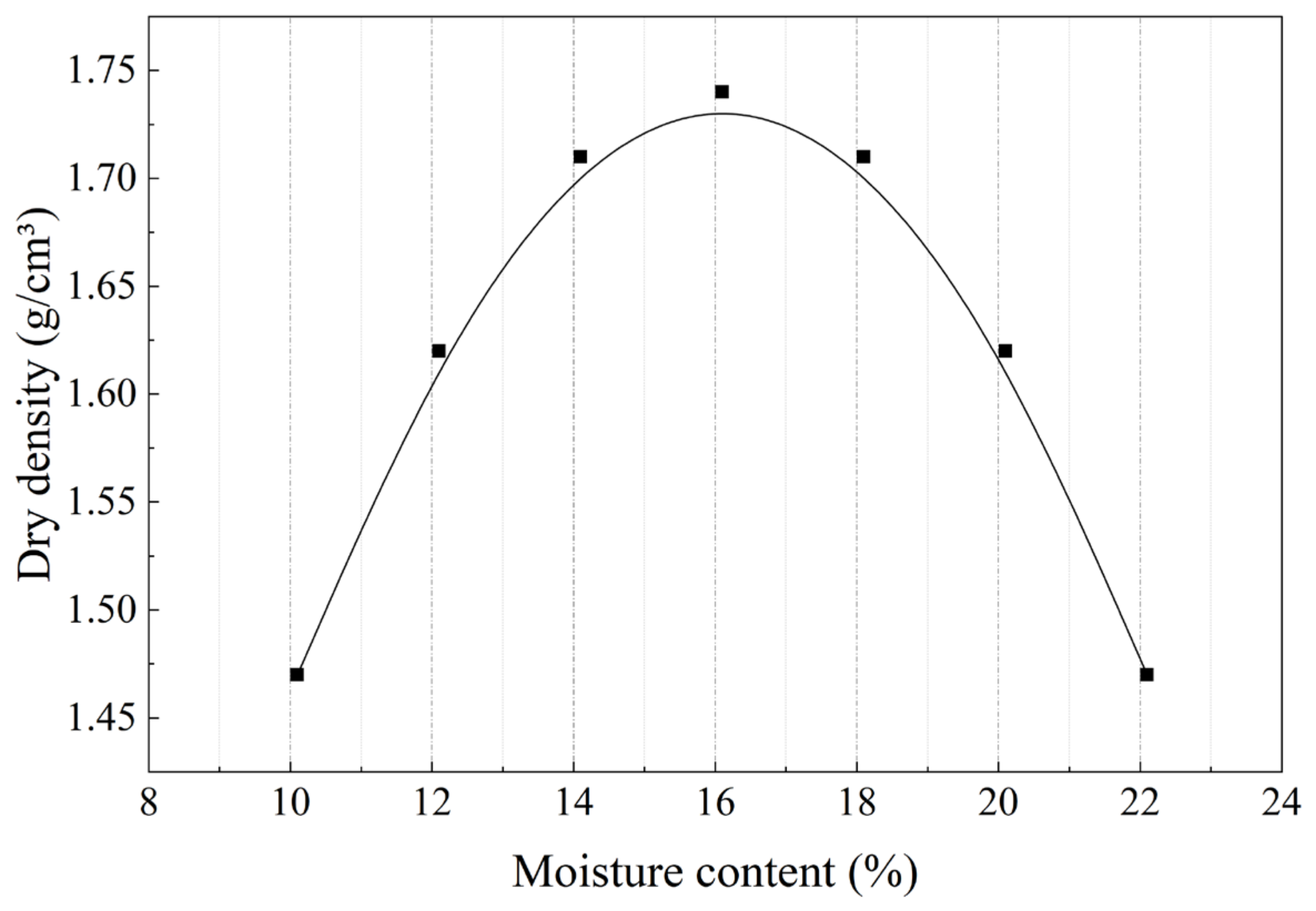
To determine the compaction parameters for subsequent specimen preparation, a standard light compaction test was conducted. The optimum moisture content and maximum dry density of the 70:30 mixed soil were determined to be 16.1% and 1.74 g/cm3, respectively, as shown in Figure 3. Different XG dosages were then selected for the comparative tests.
A fixed 3% of cement was added to the mixed soil as the basic stabilizer, and five comparative groups with different XG dosage levels were set up to explore the influence of XG dosage on the mechanical properties and W–D durability of the modified saline soil. The specific proportioning scheme is shown in Table 5. All groups had three replicate specimens, and the coefficient of variation in the replicate test results was within 5% to ensure the reliability and repeatability of the experimental data.

2.3. Specimen Preparation and Testing Methods

2.3.1. Specimen Preparation

Batching and Mixing: According to the designed proportions, the oven-dried mixed soil, cement, and XG powder were weighed. Approximately 2 kg of dry mixed soil was prepared for each batch, and the materials were mixed using a UJZ-15 laboratory vertical mortar mixer (Shanghai Leiyun Test Instrument Manufacturing Co., Ltd., Shanghai, China). To improve the dispersion uniformity of low-dosage XG in the soil, a portion of the mixed soil was first premixed with XG powder to promote its uniform distribution on soil particles. The remaining mixed soil and cement were then added and dry mixed using the forced mixer for 3 min. Subsequently, deionized water was added in three portions to achieve the designed moisture condition, followed by wet mixing for 5 min to prepare the mixture.
Moisture Equilibration: The mixed soil was immediately placed in a sealed polyethylene bag and kept in a standard curing room at 20 ± 2 °C and a relative humidity of ≥95% for 12 h to promote moisture redistribution and reduce internal moisture gradients before specimen molding.
Static Compaction Molding: Two types of standard specimens were prepared using a WAW-300E microcomputer-controlled electro-hydraulic servo universal testing machine (Shandong Luda Testing Instrument Co., Ltd., Tai’an, China) via the static pressure method: ① standard cylindrical specimens for unconfined compressive strength tests, measuring Φ50 mm × H100 mm; ② standard ring cutter specimens for direct shear tests, measuring Φ61.8 mm × H20 mm. During molding, the displacement rate was controlled at 1 mm/min, and the degree of compaction for all specimens was uniformly controlled at 96%. After reaching the target dry density, the load was held for 2 min before slow unloading. Specimens with obvious surface defects, including edge collapse, local surface peeling, cracks, or dimensional deviations exceeding ±0.5 mm, were discarded. These defects were mainly caused by insufficient uniformity during mixing and static compaction, local stress concentration during molding, weak bonding in localized areas, or disturbance during demolding, which may affect the structural uniformity of specimens and the reliability of subsequent mechanical tests.
Standard Curing: The molded specimens were immediately sealed and wrapped with polyethylene film and placed in a standard curing room at 20 ± 2 °C and a relative humidity of ≥95% for 28 d; subsequent tests were conducted after the specified curing period.

2.3.2. W–D Cycling Procedure

Indoor accelerated W–D cycle tests were conducted to simulate the deterioration effects of alternating wetting–drying environmental conditions on the performance of modified saline soil. The W–D cycle procedure was established with reference to previous studies on the wetting–drying durability evaluation of stabilized soils [15] and considering the characteristics of the modified saline soil investigated in this study. The selected drying temperature, drying duration, and wetting duration were designed to accelerate moisture migration and cyclic deterioration while maintaining the structural integrity of the specimens. The relevant soil testing procedures were conducted according to the Standard for Geotechnical Testing Method (GB/T 50123–2019), and the specific W–D cycle regime was as follows:
The specimens cured to the specified age were first weighed for their initial mass and then placed in the same forced-air drying oven at 40 °C for 2 h to remove surface free water and reduce abrupt thermal and moisture gradients before the main drying stage.
Drying: The pre-dried specimens were then dried in the same oven at 60 °C for 24 h to complete a single drying process.
Cooling: After drying for 24 h, the specimens were immediately removed from the same forced-air drying oven and transferred into a sealed desiccator containing desiccant. The specimens were naturally cooled to room temperature (20 ± 2 °C) before the subsequent wetting process.
Immersion Wetting: The specimens cooled to room temperature after drying were saturated using a progressive immersion procedure. The specimens were first partially immersed in deaired deionized water at 20 ± 2 °C to allow for gradual water penetration into the pore structure and facilitate the displacement of entrapped air. Subsequently, the specimens were completely immersed in water for complete immersion. During immersion, the water level was maintained 20 mm above the top surface of the specimens, and the specimens were kept immersed for 24 h to complete the wetting stage.
The above sequence of pre-drying, thermostatic drying, cooling, and immersion wetting was defined as one complete W–D cycle. The specimens were subjected to W–D cyclic treatments for 0, 2, 4, 6, 8, 10, 15, and 20 cycles, respectively; upon reaching the target number of cycles, the specimens were immediately removed for subsequent mechanical property tests and microstructural interface tests.
To evaluate the surface crack development and material deterioration of the specimens during W–D cycles, the crack ratio fc and mass loss rate were selected as evaluation indicators. After the specified number of W–D cycles, the specimen surfaces were photographed, and the crack areas were calculated using an image binarization processing method. The crack ratio fc was defined as the ratio of the total surface crack area to the effective observation area of the specimen:
The calculation methods for mass loss rate and crack ratio were established based on previous studies on the wetting–drying durability of biopolymer-treated soils and quantitative analysis of soil surface cracks [7,19]. The mass loss rate was calculated using Equation (1), and the crack ratio was calculated using Equation (2).
w Loss = m 0     m n m 0 × 100 %  
where: wLoss is the mass loss rate (%) after n W–D cycles; m0 is the initial dry mass of the specimen (g); mn is the dry mass of the specimen after n W–D cycles (g).
f c = S c S 0 × 100 %  
where: fc is the crack ratio of the specimen (%); Sc is the total surface crack area of the specimen (mm2); S0 is the effective observation area used for image analysis (mm2).

2.3.3. Direct Shear Test

Using a ZJ strain-controlled direct shear apparatus (Nanjing Ningxi Soil Instrument Co., Ltd., Nanjing, China), rapid direct shear tests were conducted on specimens with different numbers of cycles, strictly in accordance with the Test Methods of Soils for Highway Engineering (JTG 3430–2020) standard. Four levels of normal stress (100 kPa, 200 kPa, 300 kPa, and 400 kPa) were applied respectively. The shear displacement rate was controlled at 0.8 mm/min; the test was terminated upon reaching the peak shear strength; if no distinct peak occurred, shearing was continued to a displacement of 6 mm. Based on the test results, the cohesion and internal friction angle of the modified saline soil were calculated, and the effects of W–D cycles and XG dosage on the shear-strength parameters of the modified saline soil were systematically analyzed.

2.3.4. Unconfined Compressive Strength Test

The test was conducted using a Sansi Zongheng WDW-100 microcomputer-controlled electronic universal (fatigue) testing machine (Shenzhen Suns Technology Stock Co., Ltd., Shenzhen, China); the equipment has a force indication accuracy of ±1%, a displacement indication accuracy of ±0.5%, and a loading rate accuracy of ±0.5%, meeting the requirements of the Standard for Geotechnical Testing Method (GB/T 50123–2019). The crosshead displacement rate was set at 1 mm/min until specimen failure; load and deformation data during the test were recorded, the peak compressive strength was calculated, and the stress–strain curve was plotted to analyze the effect of coating modification on the soil failure mode and deformation characteristics.

2.3.5. Microstructural Analysis

Typical specimens after mechanical property tests were selected, and representative samples were collected from the interior of the specimens and prepared into block samples with dimensions of approximately 10 mm × 10 mm × 5 mm. The samples were immersed in absolute ethanol (99.7%, Shanghai Macklin Biochemical Technology Co., Ltd., Shanghai, China) to terminate cement hydration, followed by vacuum freeze-drying using a SCIENTZ-10N/A vacuum freeze dryer (Ningbo Scientz Biotechnology Co., Ltd., Ningbo, China) and gold sputter coating using a Q150R ES Plus sputter coater (Quorum Technologies Ltd., Laughton, East Sussex, UK). Subsequently, the microstructural morphology was examined using an SU8010 field-emission scanning electron microscope (Hitachi High-Technologies Corporation, Tokyo, Japan). The FE-SEM observations were conducted at an accelerating voltage of 5.0 kV, a magnification of 5000×, and an image scale bar of 20 μm. The analysis focused on the interfacial structures between the coating and soil particles, as well as between the coating and cement hydration products, together with pore characteristics and crack evolution, to reveal the microscopic mechanisms of XG modification and resistance to W–D-induced degradation.

3. Results and Discussion

3.1. Effect of XG Dosage on the Shear Strength of Modified Saline Soil

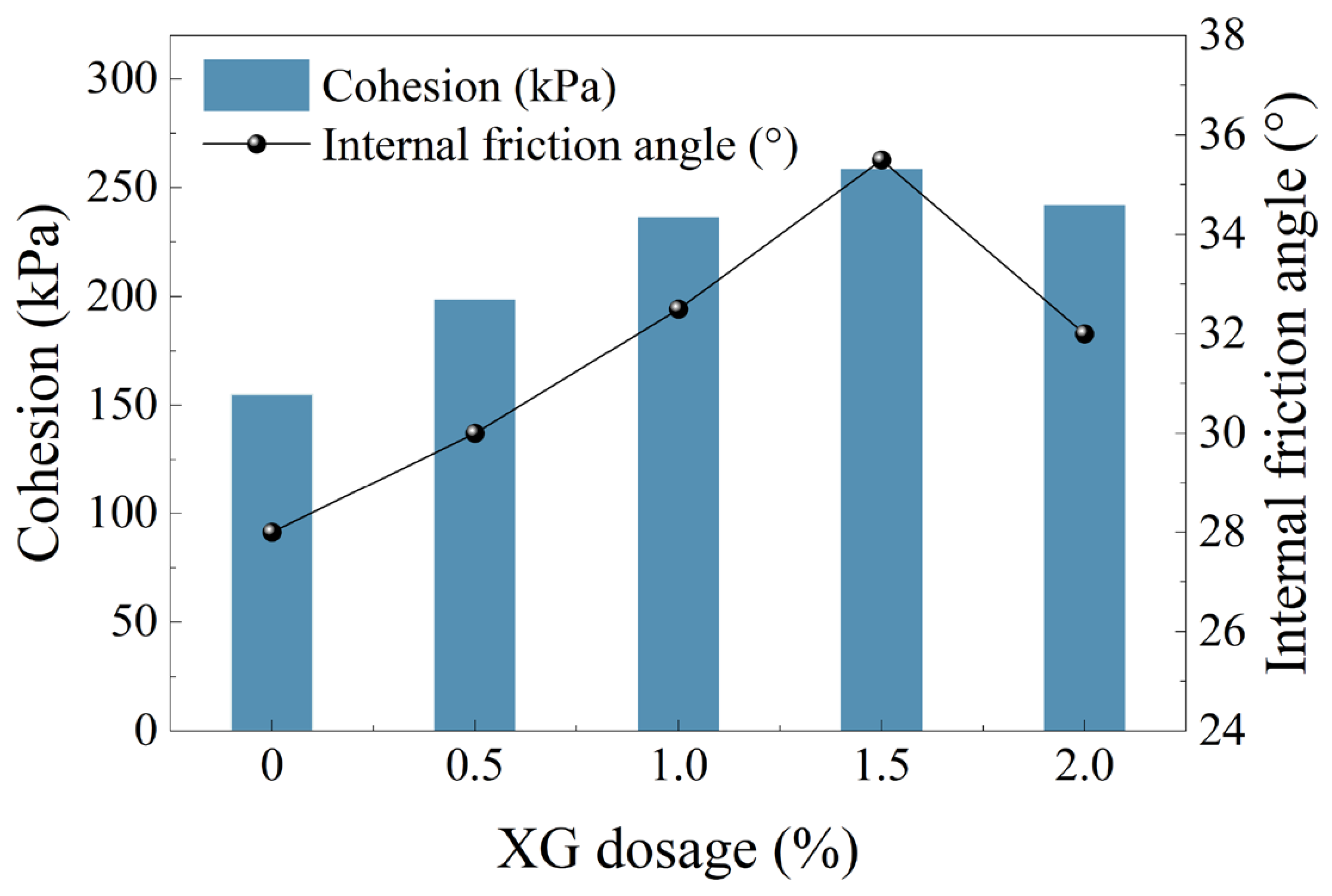
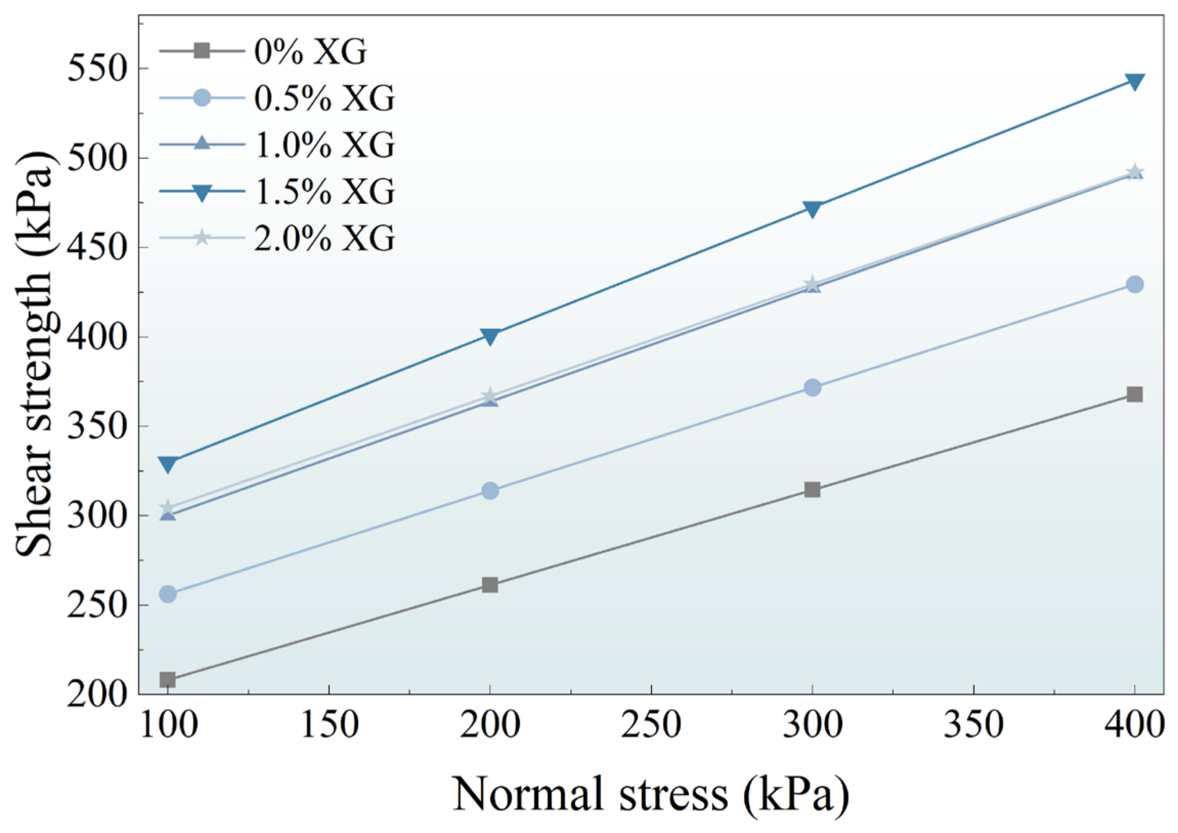
As shown in Figure 4, after 28 d of standard curing (0 W–D cycles), the shear strength of the modified saline soil increased linearly with increasing normal stress at all XG dosages, consistent with the Mohr–Coulomb strength criterion. As shown in Figure 5, the cohesion and internal friction angle of the modified saline soil first increased and then decreased with increasing XG dosage. The cohesion of the 0% XG control was 155.0 kPa, and the internal friction angle was 28.0°. At an XG dosage of 1.5%, the cohesion and internal friction angle increased to 258.5 kPa and 35.5°, respectively, reaching their maximum values. When the XG dosage increased to 2.0%, both parameters decreased slightly.
In the 70:30 mixed soil, particles of different sizes jointly form the load-bearing structure, and the interparticle contact condition and interface bonding strength determine the resistance to sliding during shear deformation. After XG incorporation, the hydrated gel structure improves interparticle connections and enhances the bonding between soil particles and cement hydration products, thereby restricting relative particle movement during shearing and increasing shear strength [20]. The marked increase in cohesion suggests that the strengthening effect of XG is mainly associated with enhanced interparticle bonding. In the present study, the 1.5% XG specimen exhibited the highest cohesion and internal friction angle, whereas both parameters decreased slightly at 2.0% XG. This trend indicates that the strengthening effect peaked near 1.5% under the present test conditions. Compared with cohesion, the change in internal friction angle was smaller because this parameter is mainly governed by particle arrangement, surface roughness, and frictional contact. XG primarily enhances interparticle bonding rather than altering the intrinsic frictional characteristics of the mineral particles.

3.2. Effect of XG Dosage on the Unconfined Compressive Strength of Modified Saline Soil

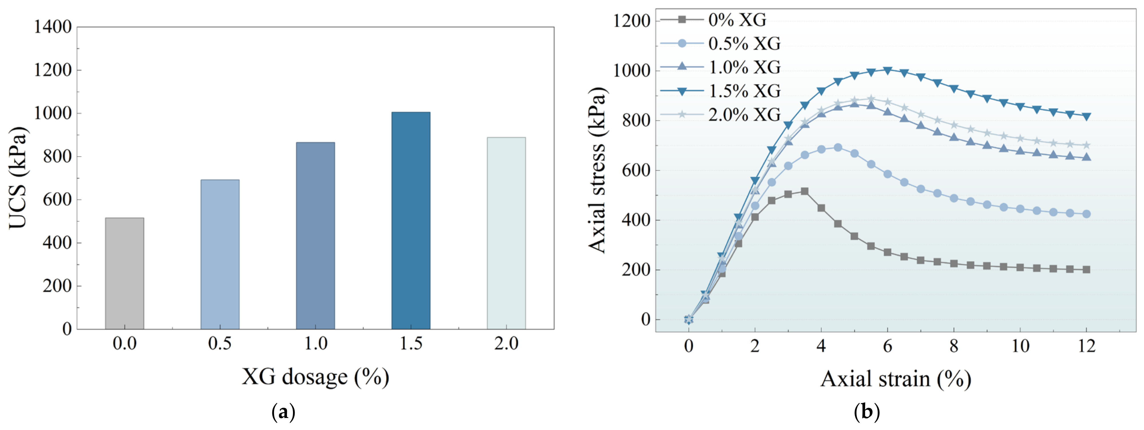
As shown in Figure 6a, the peak unconfined compressive strength of the modified saline soil first increased and then decreased as XG dosage increased. The peak strength of the 0% XG control specimen was 515.8 kPa, while the 1.5% XG specimen reached the maximum value of 1005.4 kPa, representing a 94.9% increase compared with the 0% XG control. When the dosage increased to 2.0%, the peak strength decreased, confirming an optimum XG dosage near 1.5% under the present test conditions. As shown in Figure 6b, the stress–strain curves shifted from a predominantly brittle response toward more ductile deformation as XG dosage increased. The strain corresponding to the peak stress of the 1.5% XG specimen increased to approximately 6.0%, indicating greater deformation capacity.
The improvement in compressive strength of the modified saline soil is mainly attributed to enhanced axial load transfer and the suppression of crack propagation during compression. Unlike shear failure, the compressive behavior is primarily controlled by the development of internal defects and crack coalescence under axial loading. The particle skeleton in the 70:30 mixed soil provides the basic support structure, while cement hydration products further enhance cementitious bonding between particles. After XG incorporation, the flexible gel structure improves local stress distribution, reduces stress concentration during loading, and restricts the propagation of microcracks, resulting in higher peak strength and greater deformation capacity [21]. However, at higher XG dosages, an excessive proportion of flexible gel phase may reduce the continuity of the rigid load-bearing skeleton and lower load-transfer efficiency, leading to a slight decrease in compressive strength [22]. An appropriate XG dosage balances rigid cementitious support and flexible interparticle bridging, thereby improving the overall compressive response of the modified saline soil.

3.3. Surface Deterioration and Crack Evolution

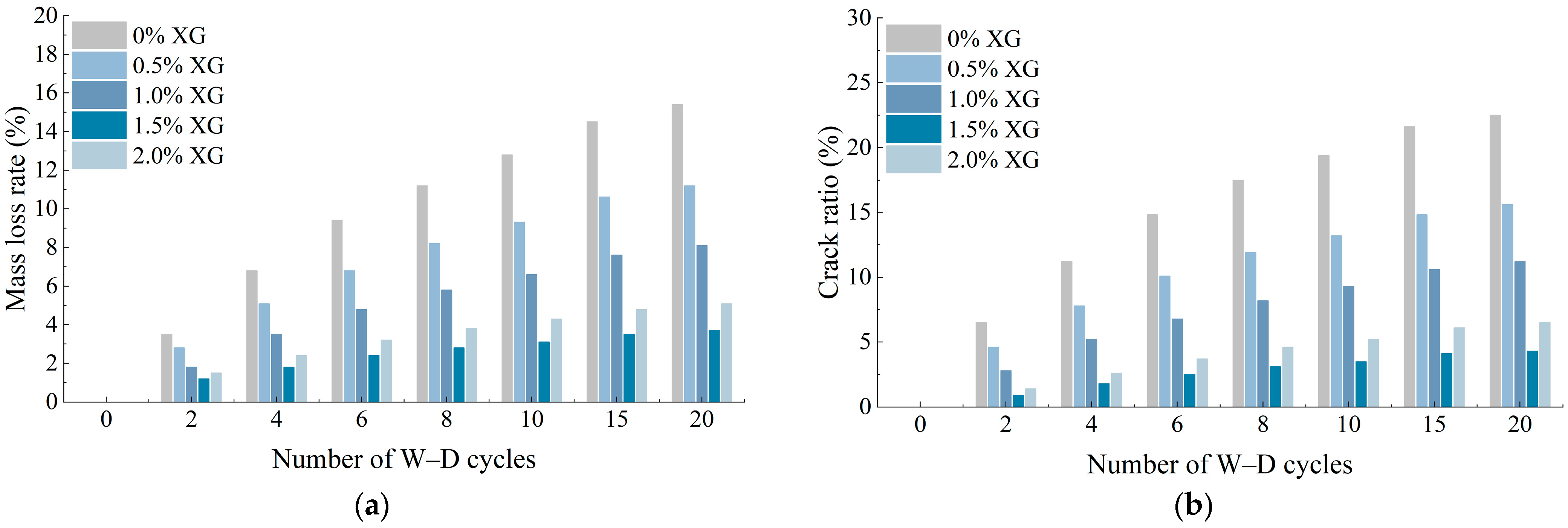
As shown in Figure 7, the crack ratio fc and mass loss rate of specimens with different XG dosages gradually increased with increasing W–D cycles, while the magnitude of increase depended on XG dosage. The 0% XG control specimens exhibited the most severe deterioration, whereas the 1.5% XG specimens maintained lower crack ratios and mass loss rates throughout the cyclic process, indicating that an appropriate XG dosage effectively mitigated surface cracking and material detachment induced by W–D cycles. In comparison, the 2.0% XG specimens exhibited slightly greater deterioration than the 1.5% XG specimens, indicating that further XG addition did not provide additional resistance to W–D cycling.
The crack ratio fc and mass loss rate represent different damage characteristics during W–D cycles. The crack ratio fc reflects the extent of surface cracking, while the mass loss rate represents surface material detachment and particle loss. Therefore, the combination of these two indicators provides an evaluation of cyclic deterioration from the perspectives of crack evolution and material loss. According to the salinity analysis, the total soluble salts (TSS) content of the original coastal saline soil was 1.25%, with Cl and SO42− contents of 6087 mg/kg and 1548 mg/kg, respectively. During repeated wetting and drying, soluble salts undergo dissolution and redistribution with moisture migration, altering the pore solution environment and potentially affecting interparticle bonding stability. Meanwhile, repeated moisture ingress and evaporation induce wetting-induced swelling and drying shrinkage, promoting crack propagation and surface particle detachment [14]. Previous studies have shown that XG can enhance interparticle bonding and improve the mechanical and hydraulic behavior of treated soils [23,24]. In the present study, the XG-containing gel structure contributed to improved interparticle bonding and interfacial continuity, which was consistent with the lower crack ratios and mass loss rates observed for the XG-modified specimens.

3.4. Effect of W–D Cycling on Mechanical Properties

3.4.1. Effect of W–D Cycling on Shear Strength

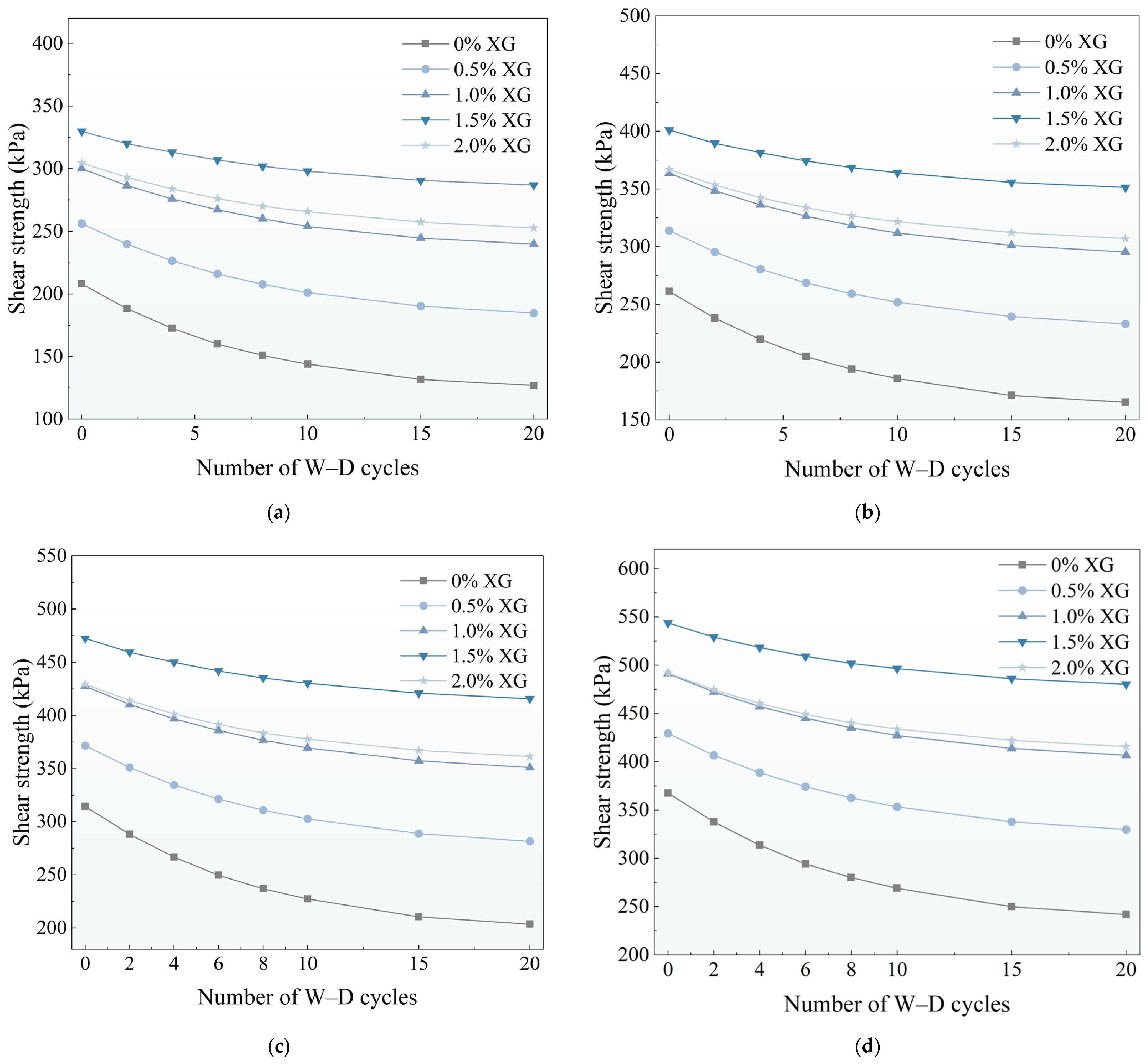
As shown in Figure 8, the shear strength of specimens under different normal stresses decreased continuously with increasing W–D cycles, while the extent of strength degradation varied with normal stress. During the first 10 cycles, the shear strength decreased significantly under all normal stresses; from 10 to 20 cycles, the reduction became less pronounced and gradually stabilized. Under the same number of W–D cycles, the shear strength increased progressively as the normal stress increased from 100 to 400 kPa, indicating that higher normal stress enhanced the shear resistance of the specimens after W–D cycling.
The reduction in shear strength during W–D cycling was mainly associated with accumulated structural damage and weakened interparticle bonding. During repeated wetting and drying, moisture migration and salt redistribution may alter interparticle bonding conditions, while moisture-sensitive clay minerals can further destabilize particle contacts and the cemented structure. The XRD results showed that rigid minerals such as quartz and feldspar are abundant in the constituent soils and contribute to particle support, whereas clay minerals are more responsive to moisture changes. After XG modification, the formed gel structure improves the stability of interparticle connections during cyclic exposure, restricts particle migration and local structural damage, and consequently reduces the loss of shear strength caused by W–D cycles [25]. Higher normal stress increases interparticle contact forces and frictional resistance, which helps maintain shear resistance after cyclic exposure. Accordingly, post-cyclic shear behavior reflects the combined effects of W–D-induced structural damage, XG-enhanced interparticle bonding, and the applied normal stress.
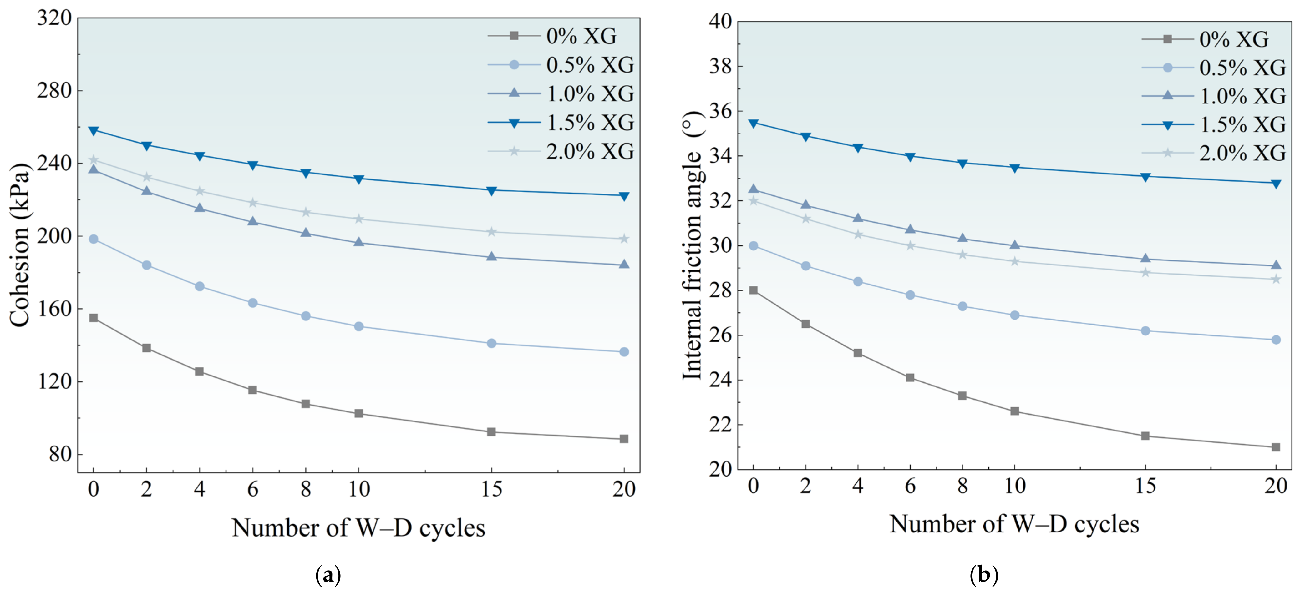
As shown in Figure 9, both cohesion and internal friction angle decreased with increasing W–D cycles, but to different extents. Cohesion was more sensitive to cyclic wetting and drying, with the 0% XG control specimen exhibiting the largest reduction, while the 1.5% XG specimen maintained a relatively higher cohesion throughout the cyclic process. The variation in cohesion with XG dosage was consistent with the shear-strength trend. In comparison, the internal friction angle decreased gradually with increasing W–D cycles, and the differences among specimens with different XG dosages were relatively smaller. The 1.5% XG specimen maintained a relatively higher internal friction angle, indicating that XG could partially alleviate the deterioration of particle structural stability during cyclic exposure.
The different responses of cohesion and internal friction angle to W–D cycles reflect their different controlling mechanisms. Cohesion reflects interparticle bonding, which is more vulnerable to bond degradation during cyclic wetting and drying, resulting in a more significant reduction. In contrast, the internal friction angle is mainly governed by particle arrangement, surface roughness, and frictional contact, and its variation mainly reflects changes in particle arrangement and frictional contact during cycling, leading to a relatively slower decrease [15]. According to the XRD results, skeletal minerals such as quartz and feldspar contribute to maintaining particle contact structures, while clay minerals participate in interfacial responses during cyclic processes. After XG modification, the formed gel structure improves interfacial stability during W–D cycles and reduces particle migration and structural damage, with a more pronounced effect on cohesion than on the internal friction angle. Therefore, W–D cycles mainly reduce shear performance by weakening interparticle bonding, while XG-enhanced interfacial bonding contributes to improved shear-strength retention after cyclic wetting and drying.

3.4.2. Effect of W–D Cycling on Unconfined Compressive Strength

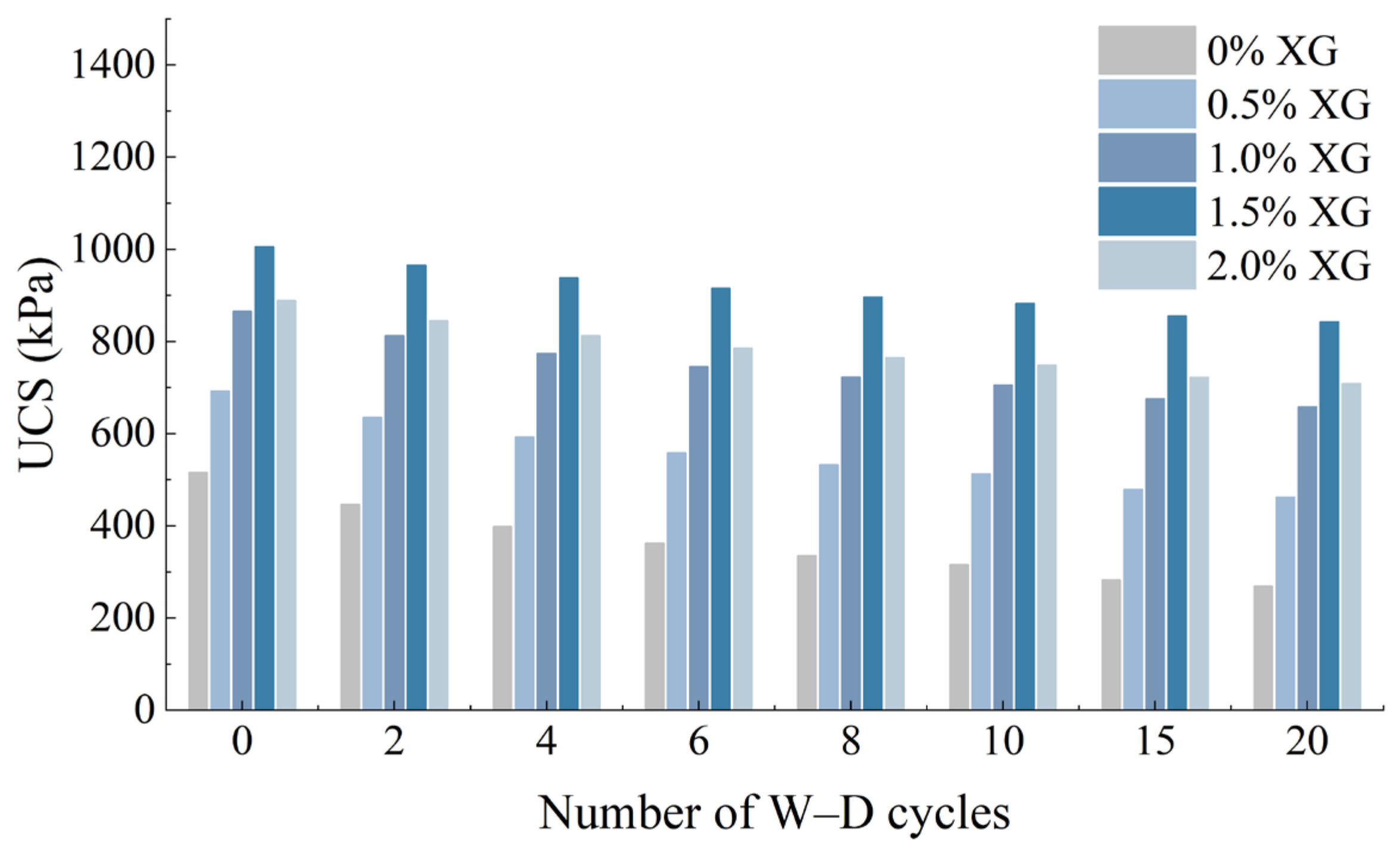
As shown in Figure 10, the UCS of all specimens decreased with increasing W–D cycles, while strength retention varied with XG dosage. Before cyclic exposure, the UCS initially increased and then decreased with increasing XG dosage, and the 1.5% XG specimen exhibited the highest UCS of 1005.4 kPa. With increasing W–D cycles, the UCS of all specimens continuously decreased. After 20 W–D cycles, the UCS values of the 0% and 1.5% XG specimens decreased to 268.5 kPa and 842.8 kPa, respectively. The 1.5% XG specimen maintained a higher strength level, indicating better compressive strength retention after cyclic exposure.
The degradation of compressive strength under W–D cycles is mainly associated with the accumulation of internal structural damage and the weakening of load-transfer paths within the soil. According to the XRD results, rigid minerals such as quartz and feldspar are abundant in the constituent soils and provide basic particle support during compression, while clay minerals such as illite and S/I-S-related phases are sensitive to moisture variation and may affect interparticle bonding conditions during cyclic processes. Under repeated wetting and drying, moisture migration and volume changes gradually weaken the interfacial structure, causing microcracks to develop around particle contact areas and reducing the effective load-bearing area, which ultimately leads to compressive strength degradation [7]. After XG incorporation, the formed gel structure improves the stability of interparticle connections, promotes load transfer between rigid mineral particles and cementitious bonds, reduces structural damage during cyclic exposure, and consequently improves strength retention [26].
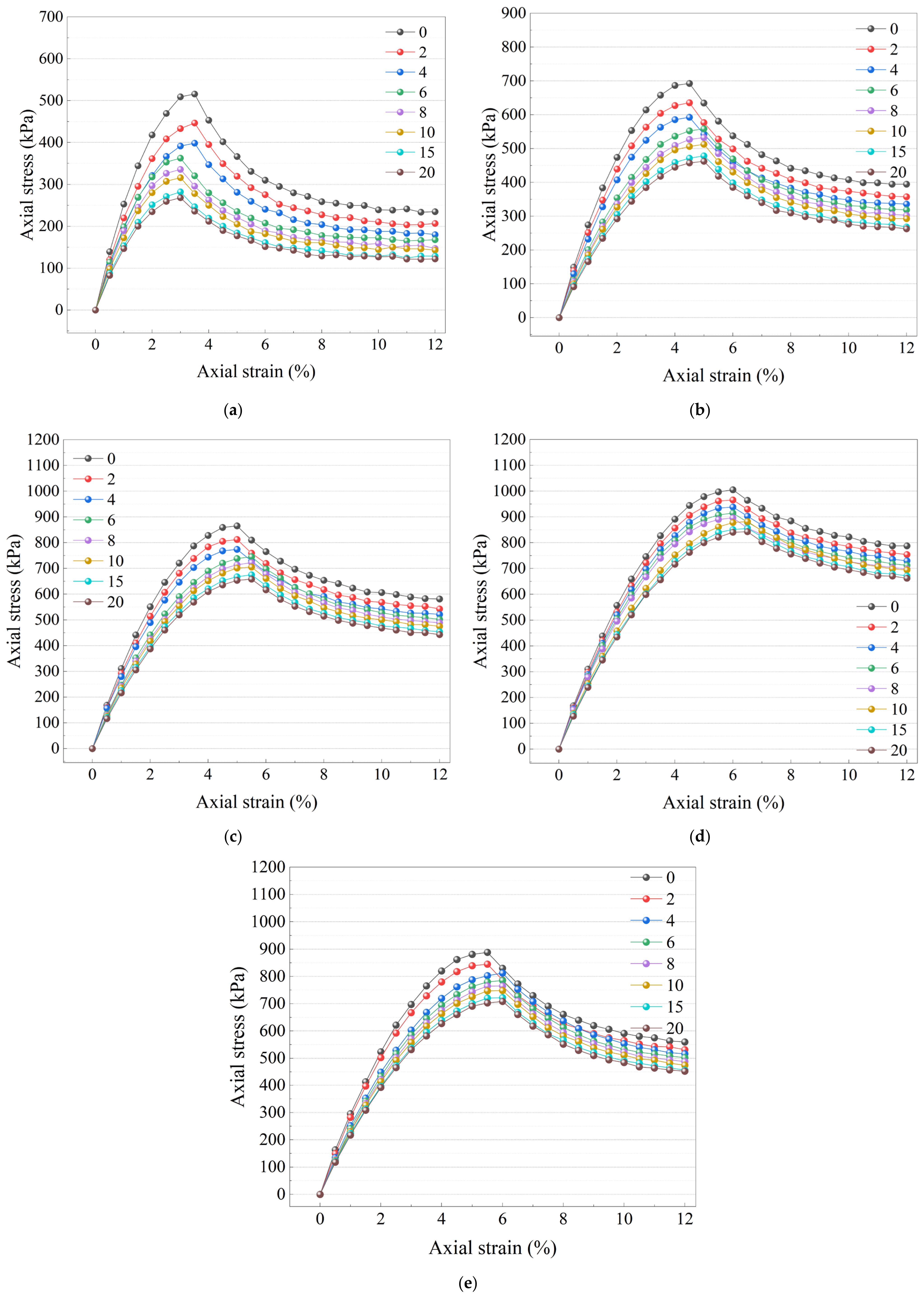
As shown in Figure 11, with increasing W–D cycles, the stress–strain curves of all specimens gradually shifted downward, and the peak stress continuously decreased, indicating progressive degradation of the compressive resistance caused by cyclic wetting and drying. The extent of degradation varied significantly with different XG dosages. The 0% XG control specimen exhibited the most significant reduction, with the peak stress decreasing from 515.8 kPa after 0 W–D cycles to 268.5 kPa after 20 W–D cycles, corresponding to a strength loss of 47.9%. In comparison, the 1.5% XG specimen maintained a higher stress level after cyclic exposure, with the peak stress decreasing from 1005.4 kPa to 842.8 kPa, corresponding to a strength loss of 16.2%. The peak stress of the 2.0% XG specimen decreased from 888.5 kPa to 708.6 kPa, showing an intermediate extent of degradation. With increasing W–D cycles, the post-peak softening became more gradual in all specimens, indicating that W–D cycles not only reduced the peak compressive strength but also altered the deformation characteristics during the failure stage.
The variation in stress–strain curves reflects the progressive internal structural damage of the soil under W–D cycles. Repeated wetting and drying weaken interparticle bonding and reduce the effective load-bearing structure, resulting in lower peak stress. According to the mineralogical analysis, skeletal minerals contribute to maintaining the particle support structure, while clay minerals and the saline environment affect interfacial stability during cyclic processes and promote damage accumulation. After XG modification, the XG-containing interfacial network limits particle migration and crack propagation, allowing the specimens to maintain higher compressive resistance and improved post-peak deformation behavior [27]. When the XG dosage reaches 2.0%, excessive XG may weaken the structural constraint effect, resulting in slightly lower cyclic performance than that of the 1.5% XG specimen. These results indicate that an appropriate XG dosage can effectively improve the resistance of soil to damage induced by W–D cycles.

3.5. FE-SEM Analysis of Microstructural and Interfacial Evolution

To examine the microstructural and interfacial changes associated with XG modification and W–D cycling, FE-SEM was used to compare the fracture surfaces of specimens containing 0% and 1.5% XG before cycling and after 10 W–D cycles.
(1)
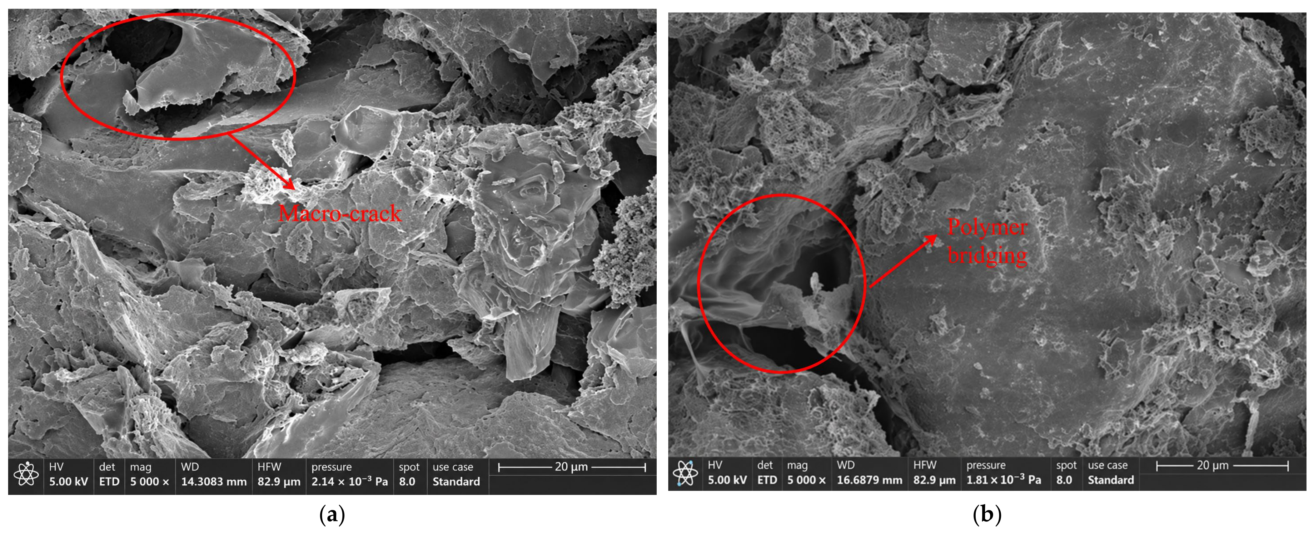
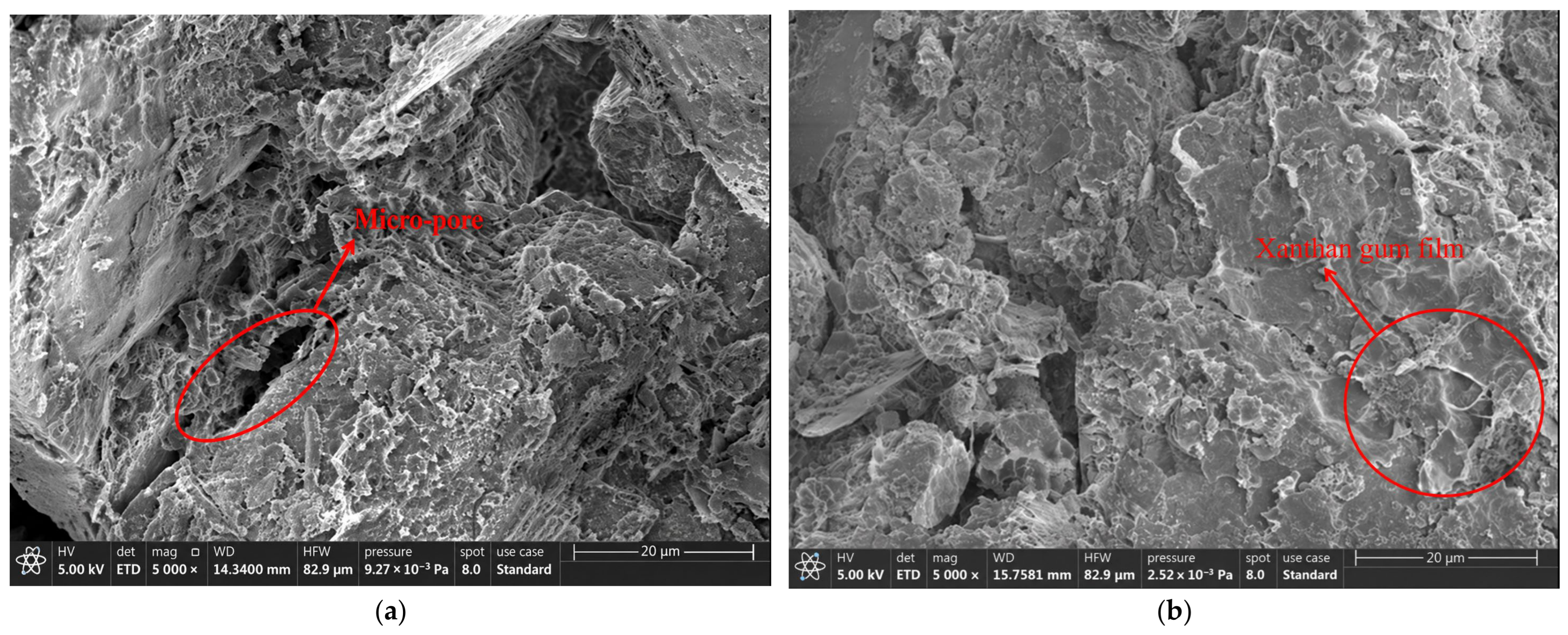
As shown in Figure 12, the specimens with different XG dosages exhibited distinct microstructural characteristics before W–D cycling. For the 0% XG control specimen, the fracture surface contained more exposed soil particles and locally connected pores. The cement hydration products were mainly distributed around particle contact areas, and the overall cemented microstructure was relatively discontinuous. In contrast, the 1.5% XG specimen exhibited a denser microstructure, with more continuous connections between particles, fewer visible pores, and stronger bonding between cement hydration products and soil particles. The red-marked regions show gel-like material coating and bridging adjacent particles, contributing to improved interfacial continuity and a more continuous cemented microstructure [20].
The XRD results showed that quartz and feldspar are abundant in both constituent soils and contribute rigid skeletal support within the microstructure. Clay minerals, such as illite and S/I-S-related phases, have relatively large specific surface areas and participate in interfacial interactions between particles [18]. After XG incorporation, the formed gel structure interacts with cement hydration products and improves interparticle bonding, enabling the original mineral skeleton and cementitious phases to form a more stable composite structure. Therefore, the 1.5% XG specimen exhibited greater microstructural continuity, providing microscopic evidence for its improved macroscopic mechanical performance.
(2)
As shown in Figure 13, after 10 W–D cycles, the specimens with different XG dosages exhibited different degrees of microstructural deterioration. The 0% XG control specimen showed more pronounced structural damage, with weakened interparticle connections, particle detachment, and pore expansion observed in some areas of the fracture surface. The red-marked regions indicate representative microcrack and pore expansion areas, suggesting progressive deterioration of the original cementation structure during cyclic wetting and drying. In comparison, although the 1.5% XG specimen developed some pores and local microcracks after cyclic exposure, the overall structure remained relatively continuous, with stable connections between particles and without extensive local fragmentation in the observed regions. The red-marked regions show bridge-like gel features and relatively intact particle contacts, suggesting that XG modification helped preserve microstructural continuity during W–D cycling.
The XRD and salinity analyses confirmed the presence of moisture-sensitive clay minerals and soluble salts in the constituent materials, both of which can influence moisture migration and interfacial stability during W–D cycling. Repeated wetting and drying may gradually weaken interparticle bonding and promote microcrack development. For the 0% XG control specimen, the absence of XG-mediated interparticle bridging resulted in more severe accumulation of cyclic damage and greater microstructural degradation [28]. After XG incorporation, the formed gel structure improved interparticle bonding and reduced interfacial deterioration associated with moisture and salt migration, allowing the microstructure to maintain better integrity after cyclic exposure [26]. Therefore, the improved microstructural stability observed in the 1.5% XG specimen corresponds to its greater mechanical-strength retention after W–D cycles.

4. Conclusions

(1)
The incorporation of XG biopolymer coating effectively improved the mechanical performance and W–D durability of modified saline soil. The reinforcement effect was closely related to the XG dosage, and an appropriate dosage could enhance particle bonding and improve the stability of the composite structure. However, excessive XG addition did not continuously improve the mechanical properties, indicating that the modification efficiency was controlled by the balance between interfacial bonding enhancement and internal structural stability.
(2)
W–D cycles caused progressive deterioration of the modified saline soil through repeated moisture migration, salt redistribution, and interfacial damage. The degradation was reflected by reductions in shear and compressive strengths and increases in crack ratio and material loss. Compared with the 0% XG control, the XG-modified specimens exhibited stronger resistance to cyclic deterioration, indicating that the XG coating could effectively mitigate the damage accumulation induced by repeated wetting and drying.
(3)
The mineral composition and saline environment played important roles in the interfacial response of the modified saline soil. The skeletal minerals such as quartz and feldspar contributed to maintaining particle support, while clay minerals and soluble salts influenced the stability of particle interfaces during moisture migration. The combination of XG coating and cement hydration products formed an organic–inorganic composite interface structure, which improved structural continuity and delayed crack propagation under W–D cycles.
(4)
The FE-SEM observations further showed that XG modification altered the microstructural characteristics and damage evolution of the saline soil. The observed gel-like features were distributed around particle contacts and cement hydration products, contributing to a relatively continuous interfacial network. During W–D cycles, the flexible bridging effect of XG helped maintain particle connections and reduced microstructural deterioration and microcrack propagation, providing a microscopic explanation for the improved durability of the modified saline soil.
(5)
This study mainly investigated the mechanical response and microstructural evolution of XG-modified coastal saline soil under accelerated laboratory W–D cycles. The tested cycle conditions, specimen dimensions, and curing environment cannot fully represent the complexity of field conditions, such as groundwater fluctuation, temperature variation, long-term salt migration, and biological degradation. Therefore, further research should combine field exposure tests and multi-scale monitoring methods to investigate the long-term durability of XG-modified saline soil under coupled environmental effects. In addition, the influence of different saline environments, XG degradation characteristics, and the long-term evolution of the XG–cement interface should be further explored to support engineering applications.

Author Contributions

Conceptualization, S.D. and C.-T.C.; methodology, S.D. and X.C.; validation, Y.D., Y.C. and C.-T.C.; formal analysis, S.D., X.C. and Y.D.; investigation, S.D., X.C., Y.D. and Y.C.; data curation, S.D., X.C. and Y.C.; writing—original draft preparation, S.D.; writing—review and editing, C.-T.C.; visualization, Y.D., X.C. and C.-T.C. All authors have read and agreed to the published version of the manuscript.

Funding

This research was funded by the Natural Science Foundation of Fujian Province, grant number 2025J011132, and the Education Foundation of Fujian Province, grant number JZ240081. The APC was funded by the Natural Science Foundation of Fujian Province.

Institutional Review Board Statement

Not applicable.

Informed Consent Statement

Not applicable.

Data Availability Statement

The raw experimental data generated and analyzed during this study are available from the corresponding author upon reasonable request.

Acknowledgments

The authors would like to thank Hongyuan Waterproof Technology Group Co., Ltd., for providing experimental raw materials and technical support for this research.

Conflicts of Interest

Author Yangfei Chen was employed by Hongyuan Waterproof Technology Group Co., Ltd. The remaining authors declare that this research was conducted in the absence of any commercial or financial relationships that could be construed as potential conflicts of interest.

References

  1. Li, G.; Ren, Z.; Liu, J.; Chen, H.; Wen, Z.; Fu, C. Enhancing Coastal saline dispersive soil with ionic stabilizer-cement synergy: Mechanisms and performance. Case Stud. Constr. Mater. 2025, 23, e05519. [Google Scholar] [CrossRef] [Scilit]
  2. Li, T.; Yang, Z.; Ma, D.; Tian, J.; Feng, H. Effects of dry–wet cycles on the dynamic characteristics of cement-stabilized loess. Bull. Eng. Geol. Environ. 2025, 84, 433. [Google Scholar] [CrossRef] [Scilit]
  3. Nouri, H.; Ghadir, P.; Fatehi, H.; Shariatmadari, N.; Saberian, M. Effects of protein-based biopolymer on geotechnical properties of salt-affected sandy soil. Geotech. Geol. Eng. 2022, 40, 5739–5753. [Google Scholar] [CrossRef] [Scilit]
  4. Castro, G.M.; Tewelde, D.; Tubaldi, E. Assessment of the use of sodium alginate for soil improvement in coastal applications. Sci. Rep. 2025, 15, 38714. [Google Scholar] [CrossRef] [Scilit] [PubMed]
  5. Soldo, A.; Miletić, M.; Auad, M.L. Biopolymers as a sustainable solution for the enhancement of soil mechanical properties. Sci. Rep. 2020, 10, 267. [Google Scholar] [CrossRef] [Scilit] [PubMed]
  6. Qin, Z.; Tian, Y.; Guo, X.; Chen, J.; Huang, H.; Ye, Z.; Wang, D.; Xu, E.; Huang, H.; Chen, X. Investigation of Water-Stability Behaviors in Coastal Mud Multiply Modified by Cement and Coarse-Particle Spoil. J. Mar. Sci. Eng. 2025, 13, 2105. [Google Scholar] [CrossRef] [Scilit]
  7. Chen, Z.; Liu, J.; Wang, Y.; Qi, C.; Ma, X.; Che, W.; Ma, K. Wetting–drying effects on the mechanical performance of xanthan gum biopolymer-stabilized soil. Environ. Earth Sci. 2024, 83, 197. [Google Scholar] [CrossRef] [Scilit]
  8. Cabalar, A.F.; Wiszniewski, M.; Skutnik, Z. Effects of xanthan gum biopolymer on the permeability, odometer, unconfined compressive and triaxial shear behavior of a sand. Soil Mech. Found. Eng. 2017, 54, 356–361. [Google Scholar] [CrossRef] [Scilit]
  9. Ma, Q.; Tao, Y.; Wu, J.; Lu, X.; Lei, J. Effect of xanthan gum on mechanical strength and microstructure of Cu (II)-contaminated soil subjected to freeze–thaw cycles. Sci. Rep. 2026, 16, 6430. [Google Scholar] [CrossRef] [Scilit] [PubMed]
  10. Cabalar, A.F.; Akbulut, N.; Demir, S.; Yildiz, O. Use of a biopolymer for road pavement subgrade. Sustainability 2023, 15, 8231. [Google Scholar] [CrossRef] [Scilit]
  11. Fateh, S.; Mansourkiaei, Y.; Shalchian, M.M.; Arabani, M.; Payan, M.; Ranjbar, P.Z. A comparison of temperature and freeze-thaw effects on high-swelling and low-swelling soils stabilized with xanthan gum. Results Eng. 2025, 25, 103719. [Google Scholar] [CrossRef] [Scilit]
  12. Sulaiman, H.; Taha, M.R.; Abd Rahman, N.; Taib, A.M. Performance of soil stabilized with biopolymer materials–xanthan gum and guar gum. Phys. Chem. Earth Parts A/B/C 2022, 128, 103276. [Google Scholar] [CrossRef] [Scilit]
  13. Hamza, M.; Nie, Z.; Aziz, M.; Ijaz, N.; Ijaz, Z.; Rehman, Z.U. Strengthening potential of xanthan gum biopolymer in stabilizing weak subgrade soil. Clean Technol. Environ. Policy 2022, 24, 2719–2738. [Google Scholar] [CrossRef] [Scilit]
  14. Xu, X.; Li, J.; Wang, Q.; Chu, H.; Lei, H.; Wang, X.; Meng, L.; Ruan, Z.; Du, H. Investigation into the mechanical properties and microscopic mechanisms of dispersive saline soil improved by environmentally friendly biopolymers. J. Environ. Chem. Eng. 2025, 13, 115222. [Google Scholar] [CrossRef] [Scilit]
  15. Soldo, A.; Miletic, M. Durability against wetting-drying cycles of sustainable biopolymer-treated soil. Polymers 2022, 14, 4247. [Google Scholar] [CrossRef] [Scilit] [PubMed]
  16. Kumar, S.A.; Sujatha, E.R. An appraisal of the hydro-mechanical behaviour of polysaccharides, xanthan gum, guar gum and β-glucan amended soil. Carbohydr. Polym. 2021, 265, 118083. [Google Scholar] [CrossRef] [Scilit] [PubMed]
  17. Mendonça, A.; Morais, P.V.; Pires, A.C.; Chung, A.P.; Oliveira, P.V. A review on the importance of microbial biopolymers such as xanthan gum to improve soil properties. Appl. Sci. 2021, 11, 170. [Google Scholar] [CrossRef] [Scilit]
  18. Arabani, M.; Shalchian, M.M. A review of the use of bio-based substances in soil stabilization. Environ. Dev. Sustain. 2024, 26, 13685–13737. [Google Scholar] [CrossRef] [Scilit]
  19. Baer, J.U.; Kent, T.F.; Anderson, S.H. Image analysis and fractal geometry to characterize soil desiccation cracks. Geoderma 2009, 154, 153–163. [Google Scholar] [CrossRef] [Scilit]
  20. Lang, L.; Li, J.; Huang, X.; Wang, P.; Zhang, W. Coupling effect of cement-stabilization and biopolymer-modification on the mechanical behavior of dredged sediment. J. Rock Mech. Geotech. Eng. 2024, 16, 3284–3298. [Google Scholar] [CrossRef] [Scilit]
  21. Al-Jabobi, A.; Bilsel, H. The effects of xanthan gum and guar gum on the mechanical properties of sand–bentonite mixtures. Sustainability 2025, 17, 5339. [Google Scholar] [CrossRef] [Scilit]
  22. Reddy, J.J.; Varaprasad, B.J.S. Long-term and durability properties of xanthan gum treated dispersive soils—An eco-friendly material. Mater. Today Proc. 2021, 44, 309–314. [Google Scholar] [CrossRef] [Scilit]
  23. Zhang, X.; Cao, W.; Zhang, X. Experimental study on mechanical and hydraulic properties of xanthan gum improved low liquid limit silty soil. Sci. Rep. 2024, 14, 11072. [Google Scholar] [CrossRef] [Scilit] [PubMed]
  24. Sujatha, E.R.; Atchaya, S.; Sivasaran, A.; Keerdthe, R.S. Enhancing the geotechnical properties of soil using xanthan gum—An eco-friendly alternative to traditional stabilizers. Bull. Eng. Geol. Environ. 2021, 80, 1157–1167. [Google Scholar] [CrossRef] [Scilit]
  25. Du, X.; Tian, H.; Kang, X.; Sun, Z.; Zhao, X.; Ren, Y. Strength and water retention behavior of loess stabilized with guar gum and fiber under dry and wet cycles. Sci. Rep. 2025, 15, 11410. [Google Scholar] [CrossRef] [Scilit] [PubMed]
  26. Gao, Q.F.; Shi, X.K.; Zeng, L.; Yu, H.C.; Hu, J.X. Characterization of the mechanical behavior and stabilization mechanism of soft soil treated with xanthan gum biopolymer. Polymers 2025, 17, 1532. [Google Scholar] [CrossRef] [Scilit] [PubMed]
  27. Bagheri, P.; Gratchev, I.; Rybachuk, M. Effects of xanthan gum biopolymer on soil mechanical properties. Appl. Sci. 2023, 13, 887. [Google Scholar] [CrossRef] [Scilit]
  28. Lee, M.; Kwon, Y.M.; Park, D.Y.; Chang, I.; Cho, G.C. Durability and strength degradation of xanthan gum based biopolymer treated soil subjected to severe weathering cycles. Sci. Rep. 2022, 12, 19453. [Google Scholar] [CrossRef] [Scilit] [PubMed]
Figure 1. Particle size distribution curves of the tested soils.
Coatings 16 01107 g001
Figure 2. XRD patterns of the tested soils: (a) sandy silt; (b) coastal saline soil.
Coatings 16 01107 g002
Figure 3. Light compaction test curve of the 70:30 mixed soil.
Coatings 16 01107 g003
Figure 4. Shear strength of modified saline soil at different normal stresses and XG dosages.
Coatings 16 01107 g004
Figure 5. Changes in cohesion and internal friction angle with XG dosage.
Coatings 16 01107 g005
Figure 6. Unconfined compressive strength and stress–strain characteristics of modified saline soil at different XG dosages. (a) Peak unconfined compressive strength; (b) Axial stress–strain curves.
Coatings 16 01107 g006
Figure 7. Evolution of specimen mass loss rate and crack ratio during W–D cycles. (a) Mass loss rate; (b) Crack ratio.
Coatings 16 01107 g007
Figure 8. Shear strength of modified saline soil after different numbers of W–D cycles. (a) normal stress of 100 kPa; (b) normal stress of 200 kPa; (c) normal stress of 300 kPa; (d) normal stress of 400 kPa.
Coatings 16 01107 g008
Figure 9. Changes in cohesion and internal friction angle at different XG dosages during different W–D cycles. (a) Cohesion; (b) Internal friction angle.
Coatings 16 01107 g009
Figure 10. Unconfined compressive strength of modified saline soil after different numbers of W–D cycles.
Coatings 16 01107 g010
Figure 11. Axial stress–strain curves of modified saline soil after different numbers of W–D cycles. (a) C3-XG0; (b) C3-XG0.5; (c) C3-XG1.0; (d) C3-XG1.5; (e) C3-XG2.0.
Coatings 16 01107 g011
Figure 12. FE-SEM images of the modified saline soil before W–D cycling. (a) C3-XG0; (b) C3-XG1.5.
Coatings 16 01107 g012
Figure 13. FE-SEM images of the modified saline soil after 10 W–D cycles. (a) C3-XG0; (b) C3-XG1.5.
Coatings 16 01107 g013
Table 1. Basic Physical Properties of Saline Soil and Sandy Silt.
IndicatorSaline SoilSandy Silt
SourceWeifang CoastalWeifang Local
Natural Moisture Content/%27.213.1
Liquid Limit wL/%41.625.3
Plastic Limit wP/%22.117.2
Plasticity Index IP19.58.1
Maximum Dry Density/g/cm31.661.83
Optimum Moisture Content/%18.511.8
Table 2. Characteristic Particle-Size Gradation Parameters of the Tested Soils.
Soil Sample NameParticle Size at 10% Passing, d10 (mm)Particle Size at 30% Passing, d30 (mm)Particle Size at 60% Passing, d60 (mm)Coefficient of Uniformity CuCoefficient of Curvature Cc
Coastal Saline Soil0.00650.01570.03074.721.23
Sandy Silt0.0260.1050.29411.311.44
70:30 Mixed Soil0.00790.02050.04525.721.18
Table 3. Semi-quantitative Mineralogical Compositions of the Tested Soils Determined by XRD Analysis.
Mineral PhaseCodeCoastal Saline Soil (%)Sandy Silt (%)
QuartzQ48.860.8
K-feldsparF6.88.5
PlagioclasePl11.413.8
CalciteC6.26
DolomiteD2.62.4
IlliteI114.8
Smectite/I-S-related phaseS/I-S5.21.6
KaoliniteK3.31.2
ChloriteCh3.20.9
HaliteH1.5
Total100100
Total clay minerals22.78.5
Table 4. Salinity Characteristics and Major Soluble-Ion Contents of the Coastal Saline Soil.
ParameterUnitValue
pH8.21
Electrical conductivity (EC)mS/cm4.18
Total soluble salts (TSS)%1.25
Na+mg/kg3582
K+mg/kg96
Ca2+mg/kg347
Mg2+mg/kg416
Clmg/kg6087
SO42−mg/kg1548
HCO3mg/kg424
Table 5. Mix Proportions of the Tested Specimens.
Specimen GroupMixed-Soil Ratio (Saline Soil:Sandy Silt)Cement Dosage (%)XG Dosage (%)
C3-XG0 (0% XG Control)70:3030
C3-XG0.570:3030.5
C3-XG1.070:3031
C3-XG1.570:3031.5
C3-XG2.070:3032
Disclaimer/Publisher’s Note: The statements, opinions and data contained in all publications are solely those of the individual author(s) and contributor(s) and not of MDPI and/or the editor(s). MDPI and/or the editor(s) disclaim responsibility for any injury to people or property resulting from any ideas, methods, instructions or products referred to in the content.