Article

Performance Analysis of a Mechanical Seal with Equilateral Triangular Textured T-Groove
School of Mechanical Engineering, Jiangxi University of Water Resources and Electric Power, Nanchang 330099, China
*
Author to whom correspondence should be addressed.
Coatings 2026, 16(8), 951; https://doi.org/10.3390/coatings16080951
Submission received: 3 July 2026 / Revised: 30 July 2026 / Accepted: 4 August 2026 / Published: 11 August 2026

Abstract

Mechanical seals in rotating machinery require sufficient liquid-film support while limiting leakage and temperature rise. This study proposes an equilateral-triangle-textured T-groove seal face and establishes a thermohydrodynamic CFD model incorporating cavitation to evaluate its lubrication and sealing behavior. The novelty lies in coupling equilateral triangular microtextures with T-grooves and assessing their combined effects on pressure generation, cavitation, thermal response, leakage, and film stability. The effects of medium pressure, rotational speed, film thickness, T-groove number, and texture depth were analyzed. The results show that the triangular textures and T-grooves jointly enhance local hydrodynamic pressure and load-carrying capacity. Higher medium pressure increases both load-carrying capacity and leakage, whereas higher rotational speed improves load support while reducing leakage. The maximum film temperature first increases and then decreases with medium pressure, peaking near 2 MPa. As film thickness increases, the load-carrying capacity reaches its maximum at approximately 8 μm, while the temperature and frictional coefficient decrease. Increasing the number of T-grooves improves load-carrying capacity and film stiffness but also increases leakage and machining complexity. Under the investigated conditions, 10–14 T-grooves provide a practical compromise among load support, leakage control, stiffness, and manufacturability.

1. Introduction

Owing to their superior durability and stable operating performance, non-contact mechanical seals are regarded as important sealing elements for high-reliability equipment and have found extensive applications in key industries such as marine engineering, aerospace, and petrochemical processing [1]. Nevertheless, under high-parameter operating conditions, excessive temperature rise and medium vaporization may occur at the seal end faces. These phenomena make it difficult to maintain a stable lubricating liquid film between the sealing interfaces, thereby weakening the operational stability of the sealing system. To further understand the underlying mechanism of hydrodynamic groove structures, previous studies have investigated end-face film formation, performance regulation, and structural optimization through theoretical calculations and physical configuration analyses [2,3,4,5]. These findings offer valuable support for maintaining the stable operation of mechanical seals.
At present, the enhancement of mechanical seal performance mainly relies on two approaches: optimization of end-face groove geometry and design of surface textures. In terms of groove-geometry optimization, previous studies have shown that the long circular-arc groove design is effective in reducing the leakage rate while improving the load-carrying capacity [6]. Meanwhile, the wavy inclined dam configuration has been found to significantly enhance the hydrodynamic effect within the sealing interface [7]. Liu et al. [8] developed a hybrid groove–elliptical mechanical seal, showing its advantages in improving sealing behavior and regulating cavitation distribution. Qiu et al. [9] indicated that the recirculation flow formed near the opening of the U-shaped groove can improve the temperature distribution within the sealing interface, thereby enhancing the sealing performance. Zhang et al. [10] compared different groove configurations and found that annular grooves were beneficial for suppressing end-face temperature rise, whereas T-shaped spiral grooves were more suitable for leakage control.
In mechanical engineering, surface texturing provides an effective means of regulating interfacial behavior and improving the operating performance of mechanical components. Zhang et al. [11] introduced bionic textures onto the seal end face and reported that scale-like textures exhibited better load-carrying capacity and sealing performance than conventional textures. Li et al. [12,13] incorporated porous structures around T-grooves and spiral grooves, respectively, and confirmed that porous structures could improve fluid-flow characteristics and further enhance liquid-film load-carrying capacity and lubrication performance. Yu et al. [14] arranged textures on the side surface of the rotor and achieved a maximum reduction of approximately 10 °C in end-face temperature. Based on a multi-objective optimization framework, Li et al. [15] investigated the influence of texture shape and identified an optimal configuration that combined zero-leakage behavior with good overall performance. He et al. [16] solved the sealing performance parameters of different textures using the successive over-relaxation iterative method and found that rectangular textures produced the most pronounced optimization effect, with the load-carrying capacity increasing by up to 81.2%. Xu et al. [17] developed a method for characterizing texture morphology and reported that the texture accommodation volume played a dominant role in performance regulation, while convergent geometries contributed to leakage control. Comparative experiments by Sato et al. [18] indicated that surface texture morphology can alter flow-field characteristics and further influence temperature distribution. Zhang et al. [19] combined numerical simulation with experimental validation and confirmed that bullet-shaped and fish-shaped textures possessed favorable comprehensive performance and good tribological characteristics. The performance of textured surfaces is strongly affected by texture geometry and spatial arrangement. Etsion [20] noted that micro-dimples can act as micro-hydrodynamic elements, fluid reservoirs, or debris traps under different lubrication conditions. Costa and Hutchings [21] further showed that texture shape, spacing, area density, depth, width, distribution, and orientation relative to the sliding direction can significantly influence hydrodynamic liquid-film formation. These findings indicate that the effect of surface texturing depends not only on the presence of textures, but also on the detailed texture parameters and their interaction with the local flow field. Morris et al. [22] demonstrated that chevron-based textures can induce local pressure perturbations and promote micro-hydrodynamic effects, thereby affecting film formation and load-carrying behavior. Therefore, surface texturing should be understood as a geometry-dependent flow-regulation strategy rather than a simple surface modification. Moreover, texture design is essentially a multi-objective optimization problem. Rahmani and Rahnejat [23] showed that optimized partial texturing can improve load-bearing performance, whereas Dobrica et al. [24] emphasized that texture extent, depth, cavitation, and leakage-related flow behavior should be considered together. This is particularly important for mechanical seals, where increased leakage may offset the benefits of improved liquid-film support.
In addition to groove-configuration and surface-texture optimization, cavitation is also an important factor affecting sealing performance. The numerical results of Bai et al. [25] showed that the cavitation region formed inside spiral grooves can reduce local pressure by 70%, thereby weakening sealing performance. Li et al. [26] pointed out that cavitation mainly occurs in low-pressure regions and is significantly affected by operating parameters and medium viscosity. Jiang et al. [27] suggested that optimizing the spiral angle of combined groove structures is an effective approach for weakening cavitation within the sealing interface. Ma et al. [28] further found that cavitation can produce a certain cooling effect, which helps reduce end-face temperature. Morris et al. [29] conducted a combined experimental and multiphase CFD study on surface-textured journal bearings, and their results showed that surface textures can promote micro-hydrodynamic effects, delay lubricant-film rupture, and modify local cavitation behavior. Although their work mainly focused on dimpled textures in journal bearings, their findings indicate that cavitation development and multiphase flow behavior should be considered when evaluating textured lubricated contacts.
Existing studies on mechanical seals have demonstrated the potential of groove-structure optimization and surface texturing for temperature control, leakage regulation, and load-carrying enhancement. However, under high-parameter operating conditions, liquid-film lubrication behavior is jointly affected by cavitation evolution, viscous thermal effects, and texture geometry, which makes the interfacial flow and heat-transfer mechanisms more complex. For T-groove mechanical seals incorporating equilateral triangular textures, the coupled effects of pressure generation, cavitation distribution, thermal response, leakage behavior, and liquid-film stability remain insufficiently clarified. To address this issue, this study proposes an equilateral-triangle-textured T-groove mechanical seal and establishes a thermohydrodynamic CFD model incorporating cavitation. The effects of medium pressure, rotational speed, film thickness, T-groove number, and texture depth on pressure, temperature, liquid volume fraction, and sealing performance are systematically investigated. The results provide theoretical support for the structural design and parameter selection of textured T-groove mechanical seals.

2. Theoretical Analysis Model

2.1. Geometric Configuration and Parameters

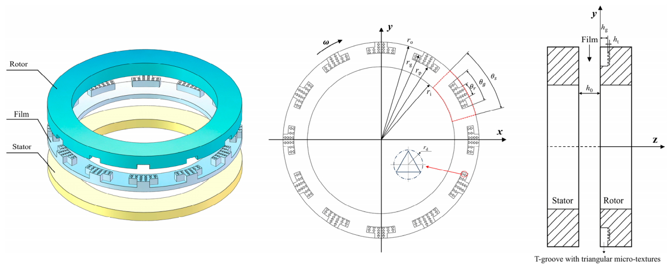
As shown in Figure 1, the proposed seal end-face structure consists of multiple periodically distributed T-grooves incorporating equilateral triangular textures. These textured grooves are arranged on the end face of the rotor, and the rotor operates at an angular velocity of ω. In Figure 1, ro, rg, rp, ri, and rd denote the outer radius of the seal ring, the pitch radius of the T-groove, the bottom radius of the T-groove, the inner radius of the seal ring, and the circumradius of the equilateral triangular texture, respectively. The parameters θ r, θ g, and θ s represent the upper-base angle, lower-base angle, and circumferential angle of the T-groove, respectively. To maintain the comparability and consistency of the numerical results, the geometric features and key parameters of the seal end face were specified uniformly, as presented in Table 1.

2.2. Governing Equations

To reduce computational complexity while obtaining reliable numerical results and representative variation trends, the following assumptions are made for the T-groove mechanical seal with equilateral triangular textures:
(1)
The end faces of the rotor and stator are regarded as two parallel sealing boundaries, and the working medium is considered to satisfy the continuum hypothesis and Newtonian-fluid behavior.
(2)
Under the investigated operating conditions, the flow within the liquid film is assumed to remain laminar, and the axial disturbance of the flow field is ignored.
(3)
The sealing medium is assumed to obey the no-slip condition on the solid walls of the sealing rings, and the effect of axial vibration on the fluid motion is not included.
(4)
Both sealing rings are modeled as rigid bodies. Accordingly, the effects of end-face elastic deformation and surface roughness on sealing characteristics are not taken into account.
On the basis of the aforementioned assumptions, a modified Reynolds equation considering the JFO cavitation effect is employed to describe the pressure variation within the lubricating liquid film:
1 r θ h 3 12 μ p θ + r h 3 12 μ p r = r ω 2 h 3 θ
To improve numerical stability and minimize the influence caused by differences in parameter dimensions, the governing equation is further converted into a dimensionless form in the following calculation:
1 R 2 θ P H 3 P θ + 1 R R P H 3 P R = Λ θ P H
The resulting dimensionless expression is given as follows:
R = r r i ,   P = p p r e f ,   H = h h 0 ,   Λ = 6 μ ω r i 2 p i h 0 2
where r and θ denote the radial coordinate and the circumferential angular coordinate, respectively; p is the liquid-film pressure; μ is the dynamic viscosity of the liquid film; h is the film thickness; and ω is the angular velocity of the rotating shaft, with the unit of rad/s. R , P , and H represent the dimensionless radius, dimensionless liquid-film pressure, and dimensionless film thickness, respectively; r i is the inner radius of the sealing end face; h 0 is the reference film thickness; p r e f is the reference pressure; and Λ is the dimensionless compressibility parameter.
The boundary conditions used for solving the numerical model are given below. The pressure boundary condition is expressed as:
p ( r i ) = p a p ( r o ) = p s
For liquid-lubricated mechanical seals operating under severe conditions, local cavitation may develop in the end-face liquid film. Therefore, cavitation-related boundary conditions are prescribed to make the numerical model more consistent with actual operating conditions. These boundary conditions are given as follows:
α l = 1 , p > p c   In   full   film   zone 0 < α l < 1 , p = p c   In   cavitation   zone
where p a , p s , and p c denote the atmospheric pressure, sealed medium pressure, and cavitation pressure, respectively; r i and r o are the inner and outer radii of the sealing end face, respectively; and α l is the liquid volume fraction.
The continuity equation of the fluid, namely the mass conservation equation, is expressed as follows:
u x + v y + w z = 0  
where u , v , and w are the velocity components of the liquid-film fluid in the x -, y -, and z -directions, respectively; x , y , and z denote the spatial coordinates. This continuity equation is used to describe the mass conservation of the incompressible sealing medium within the end-face liquid-film clearance.
The heat transfer process in the lubricating liquid film is governed by the following energy equation:
ρ m v i T x j = x j λ c p T x j + S T
For the seal rings, heat conduction is described by:
x i k r T r x i = ρ r c r U i T r x i U i = 0 ,   i = z
x i T s x i = 0
In this formulation, v i is the velocity component in the i-direction, T denotes the liquid-film temperature, c p is the specific heat capacity at constant pressure of the working medium, λ represents the thermal conductivity, and S T corresponds to the volumetric heat source term. For the rotor, its density, specific heat capacity, and thermal conductivity are denoted by ρ r , c r , and k r , respectively, with units of kg/m3, J/(kg·K), and W/(m·K). The symbols T r and T s are used for the temperatures of the rotor and stator, whereas U i indicates the velocity component of the rotor along the i-direction.
In this study, the variation in lubricant viscosity is expressed as:
μ = 0.001 e 0.0175 ( T 298.15 )
Considering the heat transfer between the sealing rings and the lubricating liquid, the numerical model applies convective heat-transfer boundary conditions to the relevant solid–fluid interface regions. To simplify the specification of thermal boundaries, an identical convective heat-transfer coefficient is assigned to the wall surfaces on both sides of the sealing rings. The corresponding expression is given as follows:
N u = 0.675 R e 1 2
h c = N u k f r o ,   R e = π n r o 2 30 ν
where N u is the Nusselt number, R e is the Reynolds number, h c denotes the convective heat transfer coefficient, k f denotes the thermal conductivity of the fluid, and ν represents the kinematic viscosity of the fluid.
The performance of the liquid-lubricated mechanical seal is assessed in terms of load-carrying capacity, leakage rate, frictional coefficient, and liquid-film stability. For this purpose, Fo, Q, f, Γ, Ftotal, and Kz are selected as the main evaluation indicators.
F 0 = Ω p d Ω
f = Ω τ d Ω / F 0
Q = S q d S
K z = F 0 h
Γ = F 0 Q
F total = N g F 0
where τ denotes the shear stress; q is the radial mass flux; S is the surface area of the pressure outlet; h is the axial distance; p is the pressure at the fluid–solid interface; K z is the liquid film stiffness; Γ is the opening-leakage ratio; Ftotal is the total load-carrying capacity; and Ω represents the fluid–solid interface area.

2.3. Numerical Method and Model Validation

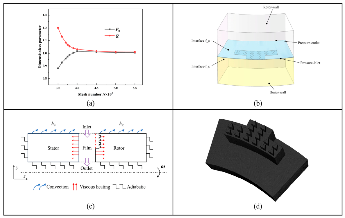
The thermophysical parameters used in the THD model of the T-groove mechanical seal with equilateral triangular textures are listed in Table 2. The computational domains were discretized using Fluent Meshing 2022. A mesh-independence study was conducted to ensure that the numerical results were not significantly affected by the mesh density. As illustrated in Figure 2a, further mesh refinement led to only minor changes in the dimensionless load-carrying capacity Fo and leakage rate Q, indicating that the calculated results became sufficiently stable. When the mesh size exceeded 5 × 10⁵ cells, both performance indicators showed negligible variation with further mesh refinement, and the relative deviation remained below 2%. Therefore, more than 5 × 10⁵ cells were adopted in all subsequent simulations to maintain sufficient numerical accuracy. In addition, the THD computational domain is presented in Figure 2b. Periodic boundary conditions were assigned to the lateral surfaces of both the solid regions and the liquid-film domain. For the liquid film, the outer-radius boundary was specified as the pressure outlet, whereas the inner-radius boundary was defined as the pressure inlet. To account for thermal interaction between the sealing-ring surfaces and the surrounding medium, convective heat-transfer boundaries were applied on the outer-radius sides of the sealing rings. Under high-duty operating conditions, heat exchange between the liquid film and the sealing rings mainly occurs through their contact interfaces; therefore, these interfaces were treated as thermally coupled surfaces. The corresponding thermal boundary conditions are illustrated in Figure 2c. At the fluid–solid interface, viscous heat generation caused by shear action was considered. The generated heat is transferred from the liquid film into the solid regions through the coupled interfaces between the film and the rotating and stationary rings. After entering the solid rings, most of the heat is dissipated into the sealing-chamber medium through convective heat transfer from the external surfaces of the rings. For simplification, the convective heat-transfer coefficients on the outer surfaces of the rotating and stationary rings were assumed to be identical and were denoted uniformly by h c , which was calculated using Equation (12). Except for the above-specified boundaries, the remaining wall surfaces were simplified as adiabatic boundaries because their heat exchange with the surroundings was relatively weak. The mesh arrangement of the fluid domain is shown in Figure 2d. Since the axial clearance of the sealing end faces is at the micrometer scale, whereas the radial dimension is at the millimeter scale, the mesh is enlarged in the axial direction for clearer visualization. To accurately resolve the pressure, velocity, and temperature gradients within the sealing clearance and along the groove-depth direction, local mesh refinement was performed in the liquid-film region. Specifically, 12 mesh layers were arranged across the film-thickness direction, and 10 layers were used along the groove depth. The total number of cells in the fluid domain exceeded 5 × 10⁵. According to the mesh-independence verification shown in Figure 2a, the numerical results obtained with the current mesh density were essentially stable. Therefore, the adopted mesh scheme was considered sufficient for the accuracy requirements of the subsequent simulations, and all following results were obtained from this single-period computational model.
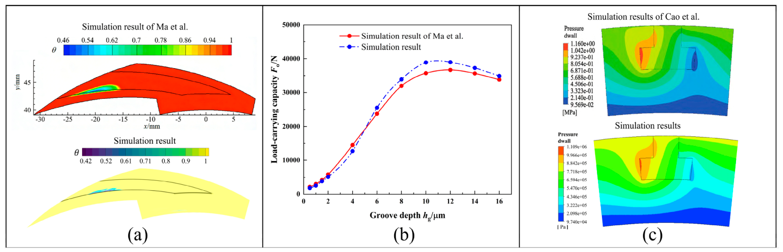
To validate the proposed numerical model, the results obtained in this study were compared with both simulation and experimental data reported in Refs. [30,31]. Figure 3a presents the simulated cavitation distribution from Ref. [30]. The comparison shows that the location and morphology of the cavitation region predicted by the present model are in good agreement with the published results. Figure 3b compares the experimental data in Ref. [30] with the corresponding results obtained in this study. A consistent variation trend can be observed, and the relative deviations are all less than 4%. In addition, Figure 3c compares the pressure distribution calculated by the present model with the pressure contour reported in Ref. [31]. The positions and shapes of the high-pressure and low-pressure regions are highly consistent with those in the reference results. Therefore, the reliability and accuracy of the proposed method are confirmed from three aspects: cavitation distribution, sealing-performance variation, and pressure-field characteristics.

3. Results and Discussion

3.1. Effect of Medium Pressure on the Performance of the T-Groove Mechanical Seal with Equilateral Triangular Textures

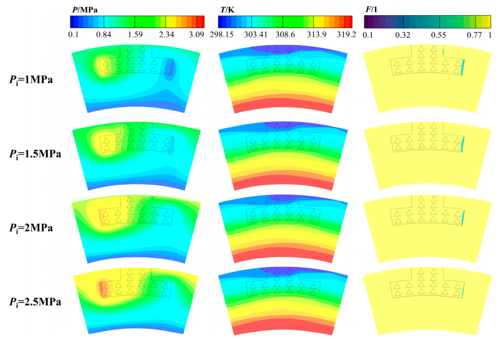
Figure 4 presents the pressure, temperature, and liquid volume fraction distributions of the mechanical seal with equilateral-triangle-textured T-grooves under various medium pressures. Owing to the hydrodynamic action of the lubricating liquid film, pressure is significantly increased on the windward side of the T-groove. As a result, this region exhibits a higher pressure than the other groove regions, forming a distinct local high-pressure zone. By contrast, a negative hydrodynamic pressure effect appears on the leeward side, where a low-pressure region is formed. With increasing medium pressure, the pressure throughout the liquid film increases simultaneously, while the pressure levels on the two sides show a similar upward tendency. Meanwhile, the high-pressure region expands, whereas the low-pressure area becomes smaller, suggesting that increasing medium pressure improves the pressure-supporting capability between the seal end faces. Moreover, cavitation occurs on the leeward side when the local pressure drops below the saturated vapor pressure of the medium, where the continuity of the liquid film is destroyed. As the medium pressure increases, the cavitation zone is gradually reduced. This behavior is further confirmed by the liquid volume fraction distribution. The liquid-phase distribution reveals that a higher medium pressure strengthens the pressure field of the liquid film, which inhibits the development of cavitation within the T-groove and leads to a smaller cavitation area. Once the medium pressure reaches 2.5 MPa, cavitation in the T-groove is largely suppressed. This phenomenon can be attributed to the increased liquid-film pressure, which helps maintain film continuity and weakens cavitation development. Owing to the proximity of the inner-diameter region of the sealing ring to the rotating shaft, the temperature field exhibits a radial distribution characterized by higher values on the inner-diameter side and lower values on the outer-diameter side. This difference leads to an evident thermal zoning pattern between the inner and outer regions of the seal end face. Under the influence of the T-groove structure with equilateral triangular textures, a distinct low-temperature inlet band is observed near the outer-radius region. This indicates that convective heat transfer between the fluid at the T-groove inlet and the medium in the sealing chamber is more sufficient, accompanied by stronger heat exchange and fluid mixing. As the medium pressure rises, the high-temperature region gradually extends toward the outer radius, while the low-temperature region decreases in area. However, the overall temperature variation remains relatively limited. In addition, the low-temperature band first narrows and then expands with increasing pressure, implying that a pressure rise within the lower pressure range promotes the end-face temperature increase, whereas further pressure elevation partially suppresses the temperature rise.
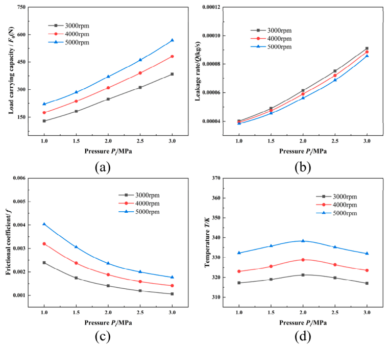
Figure 5 illustrates the variation in sealing performance of the T-groove mechanical seal with equilateral triangular textures under different medium pressures. Figure 5a indicates that the load-carrying capacity exhibits an increasing trend as the medium pressure rises. Moreover, under a given pressure level, increasing the rotational speed leads to a further improvement in load-carrying capacity. Quantitatively, the load-carrying capacity increases from 130 N to 384 N with the rise in medium pressure, giving an increment of about 195%. By comparison, the largest increase induced by rotational speed under the same pressure condition is 48.7%. The improvement in load-carrying capacity is mainly associated with the enhanced hydrostatic supporting effect of the liquid film under higher medium pressure. At the same time, the interaction between the textured surface and the T-groove structure promotes the formation of a local convergent wedge, which strengthens the hydrodynamic effect within the sealing interface. Consequently, the load-carrying capacity is further increased. The increasing slope of the curves with rotational speed also suggests that pressure and speed have a synergistic effect on improving the load-carrying behavior of the end-face liquid film. Figure 5b shows that the leakage rate increases with increasing medium pressure, while an increase in rotational speed reduces the leakage rate under the same pressure condition. This indicates that medium pressure and rotational speed have opposite effects on the leakage behavior of the liquid-lubricated mechanical seal. Specifically, the leakage rate increases from 0.000041 kg/s to 0.0000902 kg/s with increasing medium pressure, indicating that pressure is a major factor governing leakage behavior. The increase in medium pressure enlarges the pressure difference across the sealing gap. As a result, the driving force for cross-clearance flow is strengthened, leading to a higher leakage rate. Compared with the effect of medium pressure, increasing the rotational speed tends to strengthen the centrifugal inertial behavior of the liquid film and create a local resistance to flow in the groove region. This limits the cross-end-face fluid flow and contributes to a reduction in the leakage rate. Therefore, within an appropriate operating range, increasing rotational speed is beneficial for reducing the leakage rate between the seal end faces. As presented in Figure 5c, the frictional coefficient decreases rapidly at first and then declines slowly with increasing medium pressure; the frictional coefficient is enhanced under higher rotational-speed conditions. The decrease in the frictional coefficient is mainly related to the enhanced hydrostatic support between the seal end faces, which weakens the contribution of shear flow to frictional behavior. Conversely, increasing rotational speed intensifies shear action and fluid disturbance within the liquid film, resulting in a higher frictional coefficient. As shown in Figure 5d, the liquid-film temperature exhibits a non-monotonic variation with increasing medium pressure, rising first and then decreasing as the pressure continues to increase. In contrast, the end-face temperature increases further with higher rotational speed. As the medium pressure continues to increase, the cavitation region gradually contracts, indicating that the load-carrying capacity of the lubricating liquid film is enhanced. When the medium pressure reaches 2 MPa, the temperature reaches a peak value of 321.2 K and then gradually decreases with further pressure increase. This behavior suggests that, within the lower pressure range, increasing pressure enhances fluid shear and viscous dissipation between the seal end faces, leading to a temperature rise. As the medium pressure rises further, the cavitation zone is gradually reduced, while the load-supporting capability of the lubricating liquid film is enhanced. The improved film stability promotes more effective heat transfer across the sealing interface, thereby lowering the liquid-film temperature. Meanwhile, under high rotational-speed conditions, viscous shear heating within the liquid film becomes more pronounced. The increased shear-induced heat generation further promotes the rise in end-face temperature. An increase in medium pressure enhances liquid-film support and improves the load-carrying capacity of the seal face. At the same time, however, the pressure difference across the sealing clearance also increases, thereby intensifying pressure-driven leakage flow of the sealing medium. This result indicates that the improvement in liquid-film load-carrying performance is often accompanied by the negative cost of increased leakage. Therefore, when evaluating the overall sealing performance, load-carrying capacity should be considered together with leakage-related indicators, such as leakage rate and opening-leakage ratio.

3.2. Effect of Rotational Speed on the Performance of the T-Groove Mechanical Seal with Equilateral Triangular Textures

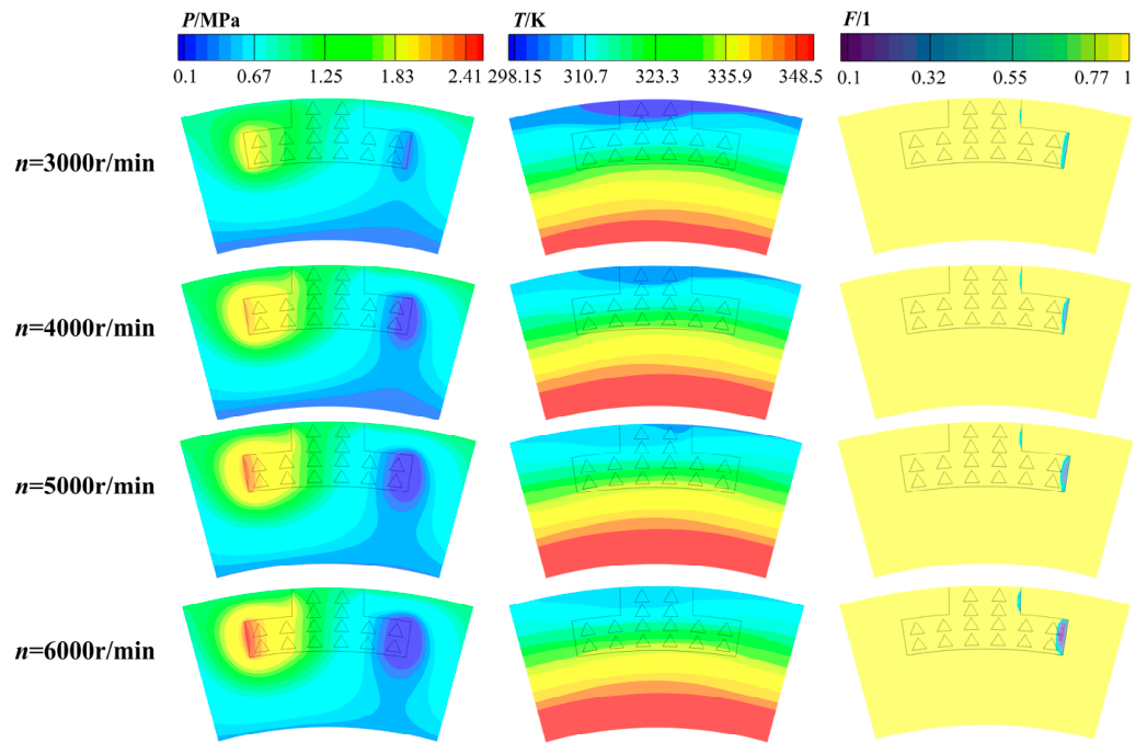
Figure 6 presents the multi-field distributions of the mechanical seal with equilateral-triangular-textured T-grooves at different rotational speeds. An increase in rotational speed strengthens the shear action within the liquid film and promotes the development of the hydrodynamic effect. As a result, the overall pressure level on the seal end face is enhanced, and the pressure field becomes more nonuniform. This behavior is characterized by a further increase in the high-pressure region, a decrease in the low-pressure region, and an expansion of both distribution areas. Under these conditions, the pressure in the low-pressure zone may drop below the saturated vapor pressure of the medium, leading to cavitation and a reduction in liquid-film continuity. The enlarged cavitation region is further confirmed by the variation in liquid volume fraction. From the perspective of temperature-field evolution, higher rotational speed causes the high-temperature region on the seal end face to extend toward the outer-diameter side. Consequently, the high-temperature area gradually expands, whereas the low-temperature region becomes smaller. When the rotational speed reaches 6000 r/min, the liquid-film temperature exhibits a distinct radial difference. The maximum temperature appears near the inner diameter, reaching approximately 353.5 K, while the minimum temperature is located near the groove opening on the outer-diameter side, with a value of 302.1 K. The maximum temperature difference between these two regions is therefore 51.4 K. These results indicate that the T-groove structure with equilateral triangular textures enhances heat exchange and fluid mixing between the fluid near the groove inlet and the medium in the sealing chamber, thereby delaying the outward expansion of the high-temperature region to some extent. In addition, the temperature field exhibits a distinct circumferential fluctuation, indicating that the groove structure can modify the local flow state on the seal end face and exert a certain regulatory effect on the temperature distribution.
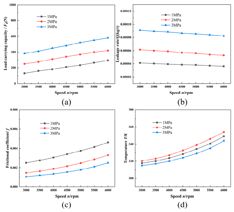
The performance characteristics of the mechanical seal with equilateral-triangular-textured T-grooves under various rotational speeds are presented in Figure 7. As indicated by the load-carrying capacity curve in Figure 7a, rotational speed plays a significant role in enhancing the load-supporting performance, with the curve showing a nearly linear increasing tendency. At a given rotational speed, increasing the medium pressure likewise results in an improvement in load-carrying capacity. This trend is mainly attributed to the intensified shear-driven flow in the liquid film at higher rotational speeds, which strengthens the hydrodynamic pressure effect. Meanwhile, the equilateral triangular textures arranged inside the T-groove induce local converging wedge effects, thereby further improving the load-carrying capability of the liquid film. Moreover, a higher medium pressure not only enhances the hydrostatic supporting capability of the interfacial fluid but also intensifies the effects of both pressure-gradient-driven flow and shear-driven flow. Quantitatively, the load-carrying capacity increases from 130 N to 294 N as the rotational speed rises, with an increment of about 126%. Under increased medium pressure, the load-carrying capacity reaches 384 N, representing an improvement of approximately 195% relative to the initial value. Therefore, within the investigated operating range, medium pressure has a stronger effect on improving the load-carrying capacity than rotational speed. As illustrated in Figure 7b, the leakage rate responds differently to rotational speed and medium pressure. At a given pressure level, raising the rotational speed helps suppress leakage, whereas an increase in medium pressure under the same speed condition tends to promote fluid loss through the sealing clearance. This reduction in leakage at higher speeds can be attributed to the enhanced centrifugal inertia of the lubricating medium. The stronger centrifugal effect restricts the inward migration of the fluid toward the inner-diameter side, causing the leakage rate to decline from 0.000041 kg/s to 0.000036 kg/s, which corresponds to an approximate decrease of 13%. By contrast, higher medium pressure increases the pressure difference across the sealing gap. The resulting pressure-driven flow becomes stronger, accelerating fluid transport from the high-pressure side to the low-pressure side and thereby increasing the leakage rate. As shown in Figure 7c, the frictional coefficient increases with rotational speed, while increasing the medium pressure under the same rotational speed contributes to a reduction in the frictional coefficient. Under the two operating conditions, the frictional coefficient shows distinctly different responses. An increase in rotational speed raises the frictional coefficient from 0.00249 to 0.00463, whereas a higher medium pressure continuously suppresses the frictional coefficient, reducing it to a minimum value of approximately 0.0011. The increase in rotational speed intensifies shear action and local fluid disturbance within the liquid film, resulting in greater viscous friction loss and thus a higher frictional coefficient. Although the equilateral triangular textures promote fluid exchange and local hydrodynamic pressure generation inside the groove, they also enhance shear effects within the film. By contrast, higher medium pressure strengthens the hydrostatic supporting effect and weakens the contribution of shear flow to frictional behavior, leading to a decrease in the frictional coefficient. Under the same rotational speed, increasing pressure reduces the frictional coefficient by 41% and 58.4%, respectively, indicating that medium pressure plays a more pronounced role in friction reduction within the present operating range. Figure 7d shows that a higher rotational speed strengthens heat generation at the seal end face, leading to a continuous temperature increase from 317.2 K to 353.5 K. By comparison, the increase in medium pressure causes the temperature to rise slightly in the initial stage, followed by a gradual decline after a peak value is reached. This trend agrees well with the previous discussion. This behavior is mainly caused by the enhanced viscous shear and energy dissipation in the liquid film at higher rotational speeds, which increases frictional heat generation and raises the end-face temperature. In the lower pressure range, increasing pressure strengthens fluid shear and heat accumulation between the seal end faces, leading to a temperature rise. When the pressure exceeds 2 MPa, the hydrostatic supporting effect is further enhanced, the cavitation region decreases, and the load-carrying state of the liquid film is improved. As a result, the shear-heating effect induced by local hydrodynamic pressure inside the groove is partially suppressed, and the end-face temperature gradually decreases. From the viewpoint of texture design, the expansion of the low-pressure region and the variation in liquid volume fraction caused by increasing rotational speed suggest that the geometric parameters of the equilateral triangular textures should be considered together with cavitation behavior. The characteristic size and depth of the textures may affect local pressure perturbation, fluid exchange, and the distribution of low-pressure regions, thereby influencing liquid-film continuity and cavitation development. Improperly selected texture parameters may weaken liquid-film support or increase leakage risk. Therefore, the size and depth of the equilateral triangular textures should not be determined solely by the enhancement of local hydrodynamic effects, but should be optimized by balancing pressure build-up, cavitation suppression, leakage control, and liquid-film stability.

3.3. Effect of Film Thickness on the Performance of the T-Groove Mechanical Seal with Equilateral Triangular Textures

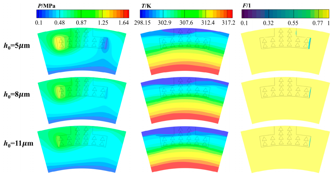
Figure 8 presents the multi-field distribution characteristics of the mechanical seal with equilateral-triangular-textured T-grooves under different liquid-film thicknesses. The pressure contours show that the differentiation of the end-face pressure field becomes progressively weaker as the liquid-film thickness increases. The distribution areas of both the high-pressure and low-pressure regions are reduced. Meanwhile, the peak pressure decreases, whereas the valley pressure rises, indicating a gradual reduction in the pressure difference within the groove region. As the liquid-film thickness increases, the sealing clearance between the end faces becomes larger, providing a wider flow space for the fluid in the gap. Consequently, the hydrodynamic effect induced by the groove structure is weakened, and the pressure gradient in the liquid film decreases accordingly. The temperature-field results indicate that the overall end-face temperature decreases with increasing liquid-film thickness. On the one hand, a larger sealing clearance allows more sealing medium to enter the friction-pair region, which enhances convective heat transfer between the fluid near the outer-diameter side and the medium in the sealing chamber. This promotes the expansion of the low-temperature region toward the inner diameter and suppresses the development of the high-temperature zone. On the other hand, the increase in liquid-film thickness weakens viscous shearing between the seal faces, thereby reducing heat generation caused by viscous dissipation. In general, a moderate increase in liquid-film thickness can modify both the flow pattern and heat-transfer mechanism at the seal end face. The larger clearance reduces the intensity of viscous shearing between the seal faces and decreases shear-dissipation heat generation, resulting in a lower end-face temperature rise. Meanwhile, the increased flow space promotes the supply of sealing medium and raises the pressure in the low-pressure region. Once the local pressure exceeds the saturated vapor pressure of the medium, cavitation is weakened, accompanied by an increase in liquid volume fraction and an improvement in liquid-film continuity.
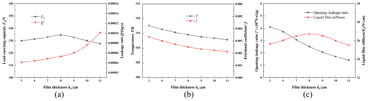
The effect of liquid-film thickness on the performance of the proposed sealing configuration is summarized in Figure 9. According to the curves in Figure 9a, film thickness does not influence load-carrying capacity and leakage rate in the same manner. As the liquid film becomes thicker, the load-carrying capacity increases slightly at the early stage and then begins to decline, while the leakage rate rises sharply throughout the investigated range. Quantitatively, the leakage rate increases by approximately 185%, whereas the largest increment in load-carrying capacity is only 0.72%. This contrast indicates that film-thickness variation has a much stronger impact on leakage behavior than on load-supporting performance. The slight enhancement of load-carrying capacity at smaller film thicknesses is mainly associated with the additional hydrodynamic support induced by the equilateral triangular texture in the groove region. When the film thickness is further enlarged, however, the wider end-face gap reduces the hydrodynamic pressure-building effect, leading to a decrease in load-carrying capacity. The continuous growth in leakage rate can be explained from two aspects. On the one hand, the reduction of the cavitation zone weakens its resistance to through-flow. On the other hand, the expanded sealing clearance provides a larger flow channel for the medium, thereby increasing the leakage rate across the sealing interface. Figure 9b reveals that an increase in film thickness produces a pronounced decline in the thermal and frictional responses of the seal pair, followed by a progressively weakened variation trend. With the enlargement of the fluid film, the maximum temperature is reduced to 311.3 K from 317.2 K, indicating an approximate decrease of 1.9%. Meanwhile, the frictional coefficient is lowered from its initial value of 0.00332 to 0.00212, corresponding to a reduction of about 36.1%. This phenomenon is mainly associated with the attenuation of viscous shearing inside the liquid film as the film thickness increases. The reduced shear action diminishes viscous dissipation heat, thereby limiting the temperature rise on the sealing end faces. In addition, the increased leakage rate enhances convective heat removal, allowing part of the generated heat to be carried away from the seal-face region by the flowing fluid and further reducing the film temperature. With respect to the frictional coefficient, an increase in film thickness reduces the circumferential velocity gradient of the fluid between the seal faces, thereby decreasing the shear stress and, consequently, the frictional coefficient. As shown in Figure 9c, the opening-leakage ratio decreases overall with increasing film thickness, whereas the film stiffness first increases and then decreases. These results indicate that a moderate increase in film thickness can improve the disturbance resistance of the liquid film within a certain range; however, it also causes a substantial increase in the leakage rate, thereby reducing the overall sealing performance. The film stiffness reaches its maximum value at a film thickness of 8 μm, suggesting that the liquid film exhibits the strongest resistance to external disturbances under this condition. When the film thickness is increased further, the film stiffness gradually decreases, accompanied by a reduction in film stability. The results related to film thickness further demonstrate the importance of leakage control in textured mechanical seals. Although increasing the liquid-film thickness within a certain range can reduce temperature rise, decrease friction, and improve the liquid-film support state, the enlarged sealing clearance also provides a wider flow passage for the medium. As a result, the increase in leakage is much greater than the increase in load-carrying capacity. This indicates that even when thermal and frictional characteristics are improved, an excessively large film thickness may still weaken the overall sealing performance of the structure. Overall, a moderate increase in film thickness contributes to reducing the seal-face temperature and improving film stiffness. Excessive film thickness, however, markedly increases the leakage rate and decreases the opening-leakage ratio. Therefore, the film thickness of an equilateral-triangle-textured T-groove mechanical seal should be selected appropriately to balance load-carrying capacity, leakage control, and operational stability.

3.4. Effect of the Number of T-Grooves on the Performance of the T-Groove Mechanical Seal with Equilateral Triangular Textures

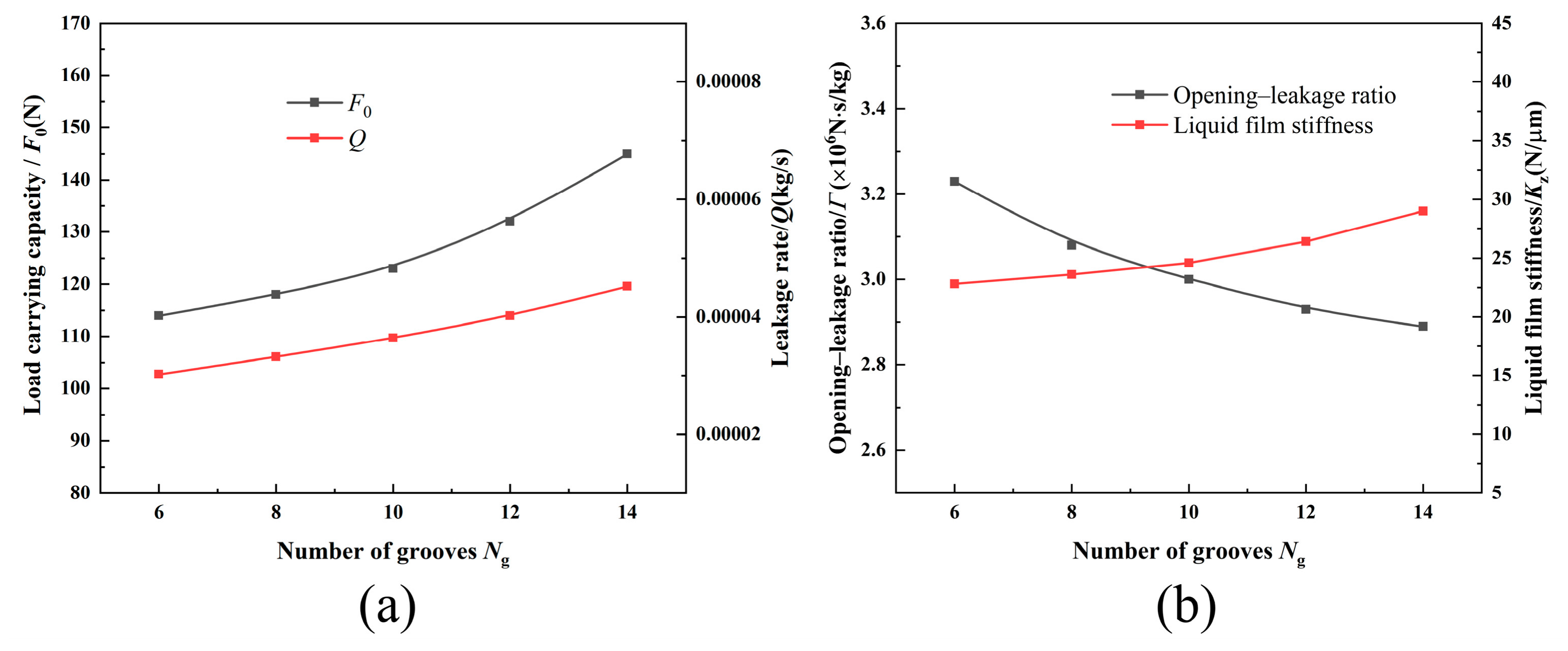
Figure 10 illustrates the influence of the number of T-grooves on the performance of the mechanical seal with equilateral triangular textures. As shown in Figure 10a, both the load-carrying capacity and leakage rate increase with the number of T-grooves. When the groove number increases from 6 to 14, the load-carrying capacity rises from 114.2 N to 145.6 N, while the leakage rate increases from 0.000301 kg/s to 0.000452 kg/s. These results indicate that introducing additional T-grooves improves the load-carrying performance of the liquid film but simultaneously aggravates fluid leakage. Therefore, the number of grooves has opposing effects on load support and leakage control. Increasing the number of T-grooves produces more locally converging wedge-shaped regions on the seal faces. In addition, the equilateral triangular textures incorporated into the grooves further strengthen the local hydrodynamic pressure effect, resulting in higher film pressure and an enhanced load-carrying capacity. However, a larger number of grooves also increases the total grooved area and creates additional fluid transport channels. Consequently, the flow capacity of the sealing medium through the interfacial clearance is enhanced, leading to an increase in the leakage rate. Figure 10b shows that the opening-leakage ratio decreases progressively with increasing groove number, whereas the film stiffness continuously increases. The improvement in film stiffness indicates enhanced resistance of the liquid film to external disturbances. In contrast, the reduction in the opening-leakage ratio suggests that less load support is obtained per unit leakage rate, thereby weakening the overall balance between load-carrying performance and leakage control. Thus, although increasing the number of T-grooves improves film stiffness and disturbance resistance, it also aggravates leakage and may adversely affect the overall sealing performance. These results further indicate that the groove number should not be determined solely by maximizing load-carrying capacity. Although more T-grooves enhance hydrodynamic pressure generation and film stiffness, they also enlarge the grooved area and provide additional leakage paths. Therefore, the groove number should be selected by balancing load support, leakage control, liquid-film stiffness, and manufacturing complexity. Considering the load-carrying capacity, leakage characteristics, film stiffness, machining complexity, and manufacturing cost, a T-groove number ranging from 10 to 14 may be selected under the operating conditions and structural parameters investigated in this study. For practical applications, the groove number should be further optimized by simultaneously considering the allowable leakage rate, required load-carrying capacity, and disturbance resistance.

3.5. Effect of Texture Depth on Sealing Performance

To further analyze the influence of texture depth on cavitation behavior and sealing performance, three models with different texture depths were compared while keeping the other conditions unchanged. The load-carrying capacity, leakage rate, minimum liquid volume fraction, and maximum temperature were selected as evaluation indicators, and the results are shown in Table 3. As the texture depth increases, the load-carrying capacity slightly increases from 129.4 N to 131.2 N, indicating that increasing texture depth can enhance local pressure perturbation and the hydrodynamic effect to a certain extent. Meanwhile, the minimum liquid volume fraction increases from 0.078 to 0.085, suggesting that, within the investigated range, an appropriate increase in texture depth helps improve local liquid-phase retention and suppress cavitation development to some extent. In addition, the maximum temperature decreases from 317.7 K to 316.4 K, indicating that deeper textures can enhance local fluid exchange and thus contribute to reducing the temperature rise at the seal end face. However, the leakage rate also increases from 0.000039 kg/s to 0.000045 kg/s as the texture depth increases. This indicates that deeper textures, while improving liquid-film support and thermal behavior, may also enlarge the local flow space and intensify leakage of the sealing medium. Therefore, texture depth should not be optimized solely for improving load-carrying capacity or reducing temperature, but should be comprehensively optimized by balancing load enhancement, cavitation suppression, leakage control, and liquid-film stability.

4. Conclusions

An equilateral-triangle-textured T-groove mechanical seal was proposed, and a thermohydrodynamic lubrication model was established using computational fluid dynamics. The effects of film thickness, medium pressure, rotational speed, T-groove number, and texture depth on film pressure, temperature, cavitation characteristics, and sealing performance were investigated. The main conclusions are summarized as follows:
(1)
The equilateral triangular textures modify the local flow and pressure distributions within the T-grooves, thereby affecting the load-carrying capacity, leakage characteristics, and frictional behavior of the liquid film. With increasing film thickness, the load-carrying capacity first increases slightly and then decreases, whereas the leakage rate continuously rises. Within the investigated range, the leakage rate increases by 185%, while the maximum increase in load-carrying capacity is only 0.72%, indicating that film thickness has a more pronounced influence on leakage behavior. A moderate increase in film thickness contributes to reducing the temperature and improving film stiffness. Excessive film thickness, however, increases the leakage rate and reduces the opening-leakage ratio. Therefore, the film thickness should be selected by jointly considering load support, leakage control, and film stability.
(2)
Increasing the medium pressure results in higher load-carrying capacity and leakage rate, whereas the frictional coefficient generally decreases. The liquid-film temperature initially increases with pressure, reaches a maximum near 2 MPa, and subsequently declines. A higher medium pressure also raises the pressure in the low-pressure region and suppresses cavitation development. When the pressure reaches 2.5 MPa, the cavitation region nearly disappears. These results demonstrate that medium pressure directly affects load support and leakage through hydrostatic support and the pressure gradient, while also altering the thermohydrodynamic behavior of the liquid film by modifying the cavitation state and local flow structure.
(3)
An increase in rotational speed strengthens the shear-driven flow and hydrodynamic pressure effect between the seal faces, resulting in increases in load-carrying capacity, frictional coefficient, and temperature. Meanwhile, the spatial extents of both the high- and low-pressure regions increase, and the pressure in the low-pressure region decreases further, leading to a stronger tendency toward cavitation. The rotation-induced centrifugal inertia partially restricts the inward leakage of the medium from the outer radius, and the leakage rate therefore decreases with rotational speed. Thus, increasing the rotational speed enhances the load-carrying capacity of the liquid film but also intensifies viscous dissipation, temperature rise, and local cavitation.
(4)
Within the operating range considered in this study, medium pressure exerts a stronger influence on the load-carrying capacity and cavitation state than rotational speed. When the number of T-grooves increases from 6 to 14, the load-carrying capacity rises from 114.2 N to 145.6 N, while the leakage rate increases from 0.000301 kg/s to 0.000452 kg/s. Increasing the groove number improves film stiffness and resistance to external disturbances but simultaneously increases leakage and reduces the opening-leakage ratio. Considering load-carrying performance, leakage control, film stiffness, machining complexity, and manufacturing cost, 10–14 T-grooves may be selected for the structure and operating conditions investigated in this study. Further optimization is required in practical applications according to the allowable leakage rate and load-carrying requirements.
(5)
The equilateral-triangle-textured T-groove structure does not improve all sealing indicators simultaneously. Its main advantages lie in enhancing local hydrodynamic pressure generation and liquid-film stiffness, whereas leakage, cavitation, temperature rise, and manufacturing complexity may become limiting factors under certain conditions. The additional texture-depth analysis further shows that increasing texture depth within the investigated range slightly improves load-carrying capacity, increases the minimum liquid volume fraction, and reduces the maximum temperature, but it also increases the leakage rate. Therefore, the proposed structure should not be optimized solely by maximizing load-carrying capacity or reducing temperature, but should be comprehensively evaluated by balancing load-carrying capacity, leakage rate, opening-leakage ratio, liquid-film stiffness, temperature rise, and cavitation extent. Future work should further optimize texture size, depth, and distribution to achieve a better balance among hydrodynamic pressure generation, cavitation suppression, leakage control, and liquid-film stability.

Author Contributions

Conceptualization, S.J.; methodology, G.K.; software, G.K. and Y.Y.; validation, G.K.; formal analysis, G.K. and S.J.; investigation, S.J.; resources, Y.R.; data curation, P.L. and Q.G.; writing—original draft preparation, G.K.; writing—review and editing, S.J.; visualization, G.K. and Y.R.; supervision, S.J.; project administration, S.J.; funding acquisition, G.K. All authors have read and agreed to the published version of the manuscript.

Funding

This work is supported by the Jiangxi Provincial Natural Science Foundation (Grant No. 20232BAB204047), the Nanchang Institute of Technology Doctoral Research Initiation Project (Grant No. 2022kyqd026), and the Science and Technology Research Project of the Jiangxi Provincial Department of Education (Grant No. GJJ211912).

Institutional Review Board Statement

Not applicable.

Informed Consent Statement

Not applicable.

Data Availability Statement

Data are contained within the article.

Conflicts of Interest

The authors declare no conflicts of interest.

Nomenclature

rRadial coordinate, mcrSpecific heat capacity of rotor, J/(kg·K)
θCircumferential angular coordinate, radcsSpecific heat capacity of stator, J/(kg·K)
pLiquid-film pressure, PacfSpecific heat capacity of fluid, J/(kg·K)
μDynamic viscosity of liquid film, Pa·sTLAmbient temperature, K
hLiquid-film thickness or axial clearance, μmNuNusselt number
ωAngular velocity of rotating shaft, rad/sReReynolds number
RDimensionless radiushcConvective heat-transfer coefficient, W/(m2·K)
PDimensionless liquid-film pressureνKinematic viscosity of fluid, m2/s
HDimensionless liquid-film thicknessnRotational speed, rpm
ΛDimensionless compressibility parameterFoLoad-carrying capacity, N
riInner radius of sealing end face, mmfFrictional coefficient
roOuter radius of sealing end face, mmQLeakage rate, kg/s
h0Reference film thickness, μmKzLiquid film stiffness, N/μm
prefReference pressure, PaΓOpening-leakage ratio, N·s/kg
paAtmospheric pressure, PaτShear stress, Pa
psSealed-medium pressure, PaqRadial mass flux, kg/(m2·s)
pcCavitation pressure, PaSSurface area of pressure outlet, m2
αlLiquid volume fractionΩFluid–solid interface area, m2
u, v, wVelocity components in x-, y-, and z-directions, m/srdCircumradius of texture, mm
x, y, zSpatial coordinates, mrgPitch radius of T-groove, mm
viVelocity component, m/srpBottom radius of T-groove, mm
xi, xjCoordinate components in tensor notation, mhgMachining depth of T-groove, μm
TLiquid-film temperature, KhtMachining depth of texture, μm
cpSpecific heat capacity of liquid-film medium, J/(kg·K)θrUpper-base angle of T-groove, °
λThermal conductivity of liquid film, W/(m·K)θgLower-base angle of T-groove, °
STHeat source termθsCircumferential angle of T-groove, °
ρmMixture density of liquid film, kg/m3NgNumber of grooves
TrRotor temperature, KNtNumber of textures inside each groove
TsStator temperature, KPiInlet pressure, MPa
UiProjection of rotor velocity in the i-direction, m/sPoOutlet pressure, MPa
krThermal conductivity of rotor, W/(m·K)
ksThermal conductivity of stator, W/(m·K)
kfThermal conductivity of fluid, W/(m·K)

References

  1. Li, X.; Meng, X.; Han, L.; Zhao, W.; Peng, X. Coupling Model and Performance Analysis of Partial Porous T-Grooved Mechanical Seal. Tribology 2025, 45, 242–252. [Google Scholar] [CrossRef]
  2. Zhao, W.; Tu, Z.; Meng, X.; Jiang, J.; Peng, X. Effect of Irregular V-Shaped Surface Texture on the Performance of Mechanical Face Seal. CIESC J. 2022, 73, 4585–4593. [Google Scholar] [CrossRef]
  3. Wang, Y.; Xie, X.; He, Y.; Huang, Z.; Xu, H.; Chai, D.; Yang, H. A New Non-Contact Fluid Seal Technology Based on Tesla Valve. Tribology 2023, 43, 975–985. [Google Scholar] [CrossRef]
  4. He, M.; Liu, Z.; Li, S.; Bi, E.; Zhang, J.; Liu, X. Optimization Method of Seal Groove Shape Based on Hydrodynamic Pressure Principle. Tribology 2023, 43, 1254–1263. [Google Scholar] [CrossRef]
  5. Ding, C.; Gong, L.; Wang, Y.; Wang, X. Experimental Study on the Influence of Surface Texturing Shape on the Friction Performance and Leakage Characteristics of Mechanical Seals. Mater. Prot. 2026, 59, 75–83. [Google Scholar] [CrossRef]
  6. Zhang, M.; Shen, Y.; Zhang, J.; Shen, Y.; Wang, W.; Wang, J. Optimization Design and Performance Analysis of Mechanical Seal End Face with Long-Arc Groove for High-Pressure Oil Delivery Pump. Chin. Hydraul. Pneum. 2025, 49, 76–87. [Google Scholar] [CrossRef]
  7. He, T.; Zhang, Q.; Yan, Y.; Dong, J.; Zhou, P. Numerical Simulation of a New Designed Mechanical Seals with Spiral Groove Structures. Lubricants 2023, 11, 70. [Google Scholar] [CrossRef] [Scilit]
  8. Liu, F.; Li, Y.; Yu, B.; Hao, M.; Sun, X.; Li, Z.; Xu, L. Experimental Research on Sealing Performance of Liquid Film Seal with Herringbone-Grooved Composite Textures. Tribol. Int. 2023, 178, 108005. [Google Scholar] [CrossRef] [Scilit]
  9. Qiu, Y.; Meng, X.; Liang, Y.; Peng, X. Thermal Mixing Effect and Heat Transfer in U-Shaped Notch on the Mechanical Seal Face. Proc. Inst. Mech. Eng. Part J J. Eng. Tribol. 2021, 235, 1924–1936. [Google Scholar] [CrossRef] [Scilit]
  10. Zhang, W.; Han, D. Study of the Sealing Performance of a High-Speed Deep Groove Mechanical Seal Thermodynamic Lubrication Model. Ind. Lubr. Tribol. 2024, 76, 991–1002. [Google Scholar] [CrossRef] [Scilit]
  11. Zhang, N.; Liu, Y.; Li, Z.; Zhan, X. Sealing Performance and Optimization Design of Squamous Textured Mechanical Seal. Tribol. Int. 2024, 193, 109425. [Google Scholar] [CrossRef] [Scilit]
  12. Li, X.; Meng, X.; Liang, Y.; Jiang, J.; Peng, X. Mass Transfer of a Hybrid Porous T-Groove Mechanical Face Seal under Elasto-Hydrodynamic Model. Heat Mass Transf. 2025, 61, 50. [Google Scholar] [CrossRef] [Scilit]
  13. Li, X.; Meng, X.; Zhao, W.; Peng, X. Numerical Investigation on a Hybrid Porous-Spiral Groove Mechanical Face Seal. Tribol. Int. 2024, 198, 109943. [Google Scholar] [CrossRef] [Scilit]
  14. Yu, M.; Peng, X.; Meng, X.; Jiang, J.; Ma, Y. Influence of Cavitation on the Heat Transfer of High-Speed Mechanical Seal with Textured Side Wall. Lubricants 2023, 11, 378. [Google Scholar] [CrossRef] [Scilit]
  15. Li, Y.; He, Y.; Luo, J. Multi-Objective Optimization of Surface Texture Shape in Fluid Mechanical Face Seals Using Mass-Conserving Cavitation Boundary Condition. Proc. Inst. Mech. Eng. Part J J. Eng. Tribol. 2024, 238, 581–599. [Google Scholar] [CrossRef] [Scilit]
  16. He, Z.; Guo, Y.; Si, J.; Li, N.; Jia, L.; Zou, Y.; Wang, H. Numerical Optimization Analysis of Floating Ring Seal Performance Based on Surface Texture. Lubricants 2024, 12, 241. [Google Scholar] [CrossRef] [Scilit]
  17. Xu, J.; Yu, S.; Ding, X.; Jiang, H.; Li, L. Performance of the Compliant Foil Gas Seal with Surface Micro-Textured Top Foil. Appl. Sci. 2022, 12, 5633. [Google Scholar] [CrossRef] [Scilit]
  18. Sato, Y.; Ochiai, M. Temperature Distribution Measurement and Internal Flow Visualization in the Lubrication Film of Non-Contacting Mechanical Seals. Tribol. Lett. 2022, 70, 93. [Google Scholar] [CrossRef] [Scilit]
  19. Zhang, H.; Hua, M.; Dong, G.; Zhang, D.-Y.; Chen, W.-J.; Dong, G.-N. Optimization of Texture Shape Based on Genetic Algorithm under Unidirectional Sliding. Tribol. Int. 2017, 115, 222–232. [Google Scholar] [CrossRef] [Scilit]
  20. Etsion, I. State of the Art in Laser Surface Texturing. J. Tribol. 2005, 127, 248–253. [Google Scholar] [CrossRef] [Scilit]
  21. Costa, H.L.; Hutchings, I.M. Hydrodynamic Lubrication of Textured Steel Surfaces under Reciprocating Sliding Conditions. Tribol. Int. 2007, 40, 1227–1238. [Google Scholar] [CrossRef] [Scilit]
  22. Morris, N.; Leighton, M.; De la Cruz, M.; Rahmani, R.; Rahnejat, H.; Howell-Smith, S. Combined Numerical and Experimental Investigation of the Micro-Hydrodynamics of Chevron-Based Textured Patterns Influencing Conjunctional Friction of Sliding Contacts. Proc. Inst. Mech. Eng. Part J J. Eng. Tribol. 2015, 229, 316–335. [Google Scholar] [CrossRef] [Scilit]
  23. Rahmani, R.; Rahnejat, H. Enhanced Performance of Optimised Partially Textured Load Bearing Surfaces. Tribol. Int. 2018, 117, 272–282. [Google Scholar] [CrossRef] [Scilit]
  24. Dobrica, M.B.; Fillon, M.; Pascovici, M.D.; Cicone, T. Optimizing Surface Texture for Hydrodynamic Lubricated Contacts Using a Mass-Conserving Numerical Approach. Proc. Inst. Mech. Eng. Part J J. Eng. Tribol. 2010, 224, 737–750. [Google Scholar] [CrossRef] [Scilit]
  25. Bai, S.; Hao, J.; Yang, J.; Song, Y. Gas–Liquid Mass Transfer Behavior of Upstream Pumping Mechanical Face Seals. Materials 2022, 15, 1482. [Google Scholar] [CrossRef] [Scilit] [PubMed]
  26. Li, Z.; Yin, X.; Yue, J.; Liu, F.; Hao, M.; Ren, B.; Xiao, B. Effects of Operating Conditions on Cavitation Induction of Spiral Groove Liquid-Film Seal (SG-LFS). Ind. Lubr. Tribol. 2020, 72, 1267–1275. [Google Scholar] [CrossRef] [Scilit]
  27. Jiang, A.; Ding, X.; Wang, S.; Li, N.; Ding, J.; Jiang, H. Simulation and Performance Analysis of Spiral Line Combined Mechanical Seals Considering Cavitation and Viscosity-Heating Effects. J. Xi’an Jiaotong Univ. 2026, 60, 261–270. [Google Scholar] [CrossRef]
  28. Ma, X.; Xiao, X. Cooling Flow and Temperature Control Mechanism in Novel Hydrodynamic-Hydrostatic Hybrid Mechanical Seals with Externally Pressurized Fluid. Appl. Therm. Eng. 2025, 265, 125561. [Google Scholar] [CrossRef] [Scilit]
  29. Morris, N.J.; Shahmohamadi, H.; Rahmani, R.; Rahnejat, H.; Garner, C.P. Combined Experimental and Multiphase Computational Fluid Dynamics Analysis of Surface Textured Journal Bearings in Mixed Regime of Lubrication. Lubr. Sci. 2018, 30, 161–173. [Google Scholar] [CrossRef] [Scilit]
  30. Ma, X.; Meng, X.; Wang, Y.; Liang, Y.; Peng, X. Fluid Inertia Effect on Spiral-Grooved Mechanical Face Seals Considering Cavitation Effects. Tribol. Trans. 2021, 64, 367–380. [Google Scholar] [CrossRef] [Scilit]
  31. Cao, G.; Mutellip, A. Analysis of the Sealing Performance of Microporous Composite Textured Bottom of E-Groove. Modular Mach. Tool Autom. Manuf. Tech. 2025, 173–176. [Google Scholar] [CrossRef]
Figure 1. End-face configuration of the textured T-groove mechanical seal incorporating equilateral-triangle patterns.
Coatings 16 00951 g001
Figure 2. Numerical model and computational settings of the T-groove mechanical seal with equilateral triangular textures: (a) grid independence test, (b) THD lubrication computational domain, (c) thermal boundary conditions, and (d) fluid-domain mesh.
Coatings 16 00951 g002
Figure 3. Validation of the numerical model: (a) Comparison with simulation results of Ma et al. [30]. (b) Comparison with simulation results of Ma et al. [30]. (c) Comparison with simulation results of Cao et al. [31].
Coatings 16 00951 g003
Figure 4. Pressure, temperature, and liquid volume fraction distributions of the T-groove mechanical seal with equilateral triangular textures under different medium pressures.
Coatings 16 00951 g004
Figure 5. Variation characteristics of mechanical seal performance under different medium pressures: (a) load carrying capacity Fo; (b) leakage rate Q; (c) frictional coefficient f; (d) temperature T.
Coatings 16 00951 g005
Figure 6. Pressure, temperature, and liquid volume fraction distributions of the T-groove mechanical seal with equilateral triangular textures at different rotational speeds.
Coatings 16 00951 g006
Figure 7. Variation characteristics of mechanical seal performance at different rotational speeds: (a) load carrying capacity Fo; (b) leakage rate Q; (c) frictional coefficient f; (d) temperature T.
Coatings 16 00951 g007
Figure 8. Pressure, temperature, and liquid volume fraction distributions of the T-groove mechanical seal with equilateral triangular textures under different liquid-film thicknesses.
Coatings 16 00951 g008
Figure 9. Variation characteristics of mechanical seal performance under different film thicknesses: (a) load carrying capacity Fo and leakage rate Q; (b) frictional coefficient f and temperature T; (c) opening-leakage ratio Γ and liquid film stiffness Kz.
Coatings 16 00951 g009
Figure 10. Variation characteristics of mechanical seal performance with different numbers of T-grooves: (a) load carrying capacity Fo and leakage rate Q; (b) opening-leakage ratio Γ and liquid film stiffness Kz.
Coatings 16 00951 g010
Table 1. Main dimensional parameters, texture-related variables, and operating conditions adopted for the numerical model.
ParameterValueParameterValue
Inner radius of the rotor and stator rings, r i /mm58.42Upper-base angle of the T-groove θ r 2.10°
Outer radius of the rotor and stator rings, r o /mm77.78Lower-base angle of the T-groove, θ g 18°
Film thickness, h o / μ m 5Circumferential angle of the T-groove, θ s 30°
Circumradius of the texture, r d /mm1Number of T-grooves, N g 12
Pitch radius of the T-groove, r g /mm37Number of textures inside each groove, N t 16
Bottom radius of the T-groove, r p /mm34.5Medium pressure, Pi/MPa1–2.5
Machining depth of the T-groove, h g / μ m 4Rotational speed, n/rpm3000–6000
Machining depth of the texture, h t / μ m 1Ambient pressure, Po/MPa0.1
Table 2. Thermophysical parameters used in the THD model.
Parameter Value Parameter Value
Rotor materialSilicon carbideStator materialGraphite
Thermal conductivity of rotor, kR [W/(m·K)]150Specific heat capacity of rotor, cR [J/(kg·K)]720
Thermal conductivity of stator, kS [W/(m·K)]45Specific heat capacity of stator, cS [J/(kg·K)]900
Thermal conductivity of fluid, kf [W/(m·K)]0.8Specific heat capacity of fluid, cf [J/(kg·K)]4600
Ambient temperature, TL [K]298.15Sealing mediumWater
Table 3. Effect of different equilateral triangular texture depths on the sealing performance of the T-groove mechanical seal.
ht/μmLoad Capacity/NLeakage Rate/kg·s−1Minimum Liquid Volume FractionMaximum Temperature/K
0.5129.40.0000390.078317.7
1.01300.0000410.081317.2
1.5131.20.0000450.085316.4
Disclaimer/Publisher’s Note: The statements, opinions and data contained in all publications are solely those of the individual author(s) and contributor(s) and not of MDPI and/or the editor(s). MDPI and/or the editor(s) disclaim responsibility for any injury to people or property resulting from any ideas, methods, instructions or products referred to in the content.