Article

Pitting Corrosion Resistance of LDED-Manufactured IN625-YSZ Coatings Exposed to Sulfide-Containing NaCl Solution


1
Special Equipment Safety Supervision Inspection Institute of Jiangsu Province, Nanjing 210009, China
2
School of Materials Science and Engineering, Jiangsu University of Science and Technology, Zhenjiang 212100, China
*
Authors to whom correspondence should be addressed.
Coatings 2026, 16(8), 929; https://doi.org/10.3390/coatings16080929
Submission received: 27 June 2026 / Revised: 26 July 2026 / Accepted: 30 July 2026 / Published: 4 August 2026
(This article belongs to the Special Issue Coating Innovations in Energy-Assisted Deposition)

Abstract

Pitting corrosion is a more insidious and dangerous failure mode than uniform corrosion for protective coatings in marine environments, especially when sulfide ions (S2−) are present. In this work, Inconel 625 (IN625) and IN625-5 wt.% yttria-stabilized zirconia (YSZ) composite coatings were fabricated on 20G steel by laser-directed energy deposition (LDED) using optimized parameters. The coatings exhibit dense microstructures, with porosities of 1.87% ± 0.10% and 1.67% ± 0.10%, respectively. The pitting resistance was systematically evaluated by cyclic potentiodynamic polarization (CPP) and electrochemical impedance spectroscopy (EIS) in 3.5 wt.% NaCl solution without and with 20 ppm Na2S. The CPP results show that the addition of YSZ decreases the pitting potential (Epit) and protection potential (Eprot), indicating reduced resistance to pit initiation, while the smaller hysteresis loop suggests an improved tendency for repassivation. S2− induces a notable drop in Eprot and impairs repassivation for both coatings, yet the IN625-YSZ coating retains a slightly higher Eprot than IN625. EIS analysis reveals that the IN625-YSZ coating in S2−-containing solution shows an increased Rct of 2.738 × 10⁵ Ω·cm2 compared with its counterpart in 3.5 wt.% NaCl solution, while the corresponding RL decreases to 2.513 Ω·cm2, suggesting a weakened outer barrier layer despite partial interfacial blocking. Post-corrosion morphology shows that YSZ particles act as preferential pitting nucleation sites; in sulfide-free solution they produce numerous shallow pits, whereas in S2−-containing solution they lead to larger and deeper pits. The results may provide a reference for the future design and evaluation of LDED-manufactured composite coatings under sulfide-containing marine environments.

1. Introduction

Marine engineering structures often suffer from localized corrosion, among which pitting is particularly dangerous because it can lead to sudden failure without significant mass loss [1,2]. For protective coatings applied in seawater, the presence of aggressive anions such as chloride (Cl) and sulfide (S2−) strongly promotes pit initiation and growth. Sulfide ions are commonly found in marine environments with biological activity or industrial pollution, and they have been reported to destabilize passive films on nickel-based alloys [3,4].
Nickel-based composite coatings reinforced with ceramic particles (e.g., YSZ, WC, TiC) are increasingly fabricated by LDED to improve wear resistance and hardness [5,6]. However, the addition of ceramic particles inevitably introduces interfaces, pores, and micro-defects, which can act as preferential sites for pit nucleation [7,8]. The pitting behavior of such composite coatings, especially under S2−-containing conditions, remains poorly understood.
Praharaj, A.K. et al. [9] investigated the effect of scanning speed on the corrosion performance of laser-directed energy deposited Inconel 625 in 3.5 wt% NaCl solution. It was observed that the sample deposited at high scanning speed exhibited the finest grains, highest dislocation density and lowest volume fraction of secondary phases, resulting in the highest corrosion potential and lowest corrosion current density (Icorr). Surface analysis further indicated that the as-deposited specimens were more susceptible to localized corrosion than to pitting corrosion. Long, H. et al. [10] studied the optimization of laser cladding process parameters for Ni-based coatings on 45# steel via response surface method and reported that the optimized coating achieved an Icorr of 7.623 × 10⁻⁷ A/cm2 and a corrosion potential (Ecorr) of −0.292 V, along with favorable wear resistance. Previous studies on LDED-manufactured IN625-YSZ coatings have mainly focused on overall corrosion performance using conventional Tafel polarization and EIS at open-circuit potential [11]. However, these methods mainly describe general corrosion behavior and cannot directly reveal pitting initiation and repassivation in sulfide-containing chloride media. While these methods provide information on uniform corrosion rates, they do not directly assess pitting susceptibility or repassivation ability.
CPP is a standard technique for evaluating pitting resistance, as it provides the Epit, Eprot, Ecorr and hysteresis loop area, which reflect the ease of pit initiation and the ability to repassivate [12,13]. Gola, K. et al. [14] investigated the effect of the microstructure of LPBF- and LDED-fabricated Inconel 625 on corrosion resistance in sulfuric acid solution. It was found that after 180 days of immersion, the area fraction of corrosion pits reached 9.63% for LPBF and 4.49% for LDED, and pits preferentially initiated at melt pool boundaries, grain boundaries, cell walls and near precipitates. The more severe pitting in LPBF was attributed to a more refined microstructure that provides a higher density of preferential sites for localized corrosion. Rezayat, M. et al. [15] evaluated the influence of laser cladding parameters on the corrosion resistance of coatings, with emphasis on pitting behavior. Electrochemical tests and SEM observations revealed that increasing laser power promotes pitting corrosion and surface defects, while the release of Mo and Cr ions into the solution improves the protectiveness of the passive film by occupying defects and thus suppressing further dissolution. While Zeng, X. et al. [16] investigated pitting corrosion of Monel K500 in sulfurous environments and showed that pits initiated preferentially at TiC precipitate interfaces via micro-galvanic coupling. The passivation film formed in Na2S solution was loose and non-protective, composed of porous NiS and Cu2S, and sulfide accumulation inside pits triggered catalytic-occluded cell acidification, driving sustained pitting growth.
Although previous work has shown that pits tend to initiate at melt pool boundaries, grain boundaries, and precipitate interfaces, the combined influence of S2− and YSZ-induced interfaces on localized corrosion in LDED-fabricated IN625-YSZ coatings has not been systematically clarified. In particular, it remains unclear whether YSZ-related interfaces act as preferential pitting sites and how sulfide ions affect passive-film stability and repassivation. Therefore, it is necessary to combine CPP, EIS, and corrosion morphology analysis to systematically evaluate the pitting behavior and mechanism of LDED-fabricated IN625-YSZ coatings in sulfide-containing chloride solutions.
In this study, we systematically investigate the pitting corrosion resistance of LDED-manufactured IN625 and IN625-YSZ coatings in 3.5 wt.% NaCl solution without and with 20 ppm Na2S. The objectives are: (i) to compare the pitting behavior using CPP and EIS; (ii) to identify the role of YSZ particles in pit initiation; and (iii) to clarify the effect of S2− on the passive film stability and repassivation ability. This study provides preliminary insight into the pitting corrosion behavior of LDED-manufactured IN625 and IN625-YSZ coatings in sulfide-containing chloride environments, which may be useful for future coating design and corrosion assessment.

2. Experimental Procedures

2.1. Coating Fabrication

In this study, IN625 powder (Xi’an Hanhai New Material Technology Co., Ltd., Xi’an, China) with a particle size range of 53–150 µm and YSZ powder (Shanghai Liantian Materials Technology Co., Ltd., Shanghai, China) with a size range of 45–75 µm were used as feedstock powders. The substrate was 20G steel. The nominal chemical compositions of the powders and the substrate are listed in Table 1 and Table 2, respectively. The mixed powder consisted of 95 wt.% IN625 and 5 wt.% YSZ were blended in a planetary ball mill at a ball-to-powder ratio of 1.5:1 and a rotation speed of 300 r/min for 10 h to obtain a homogeneous mixture. Figure 1 shows the morphology of the IN625 powder, YSZ powder, and their mixture. All powders exhibit good sphericity, indicating favorable flowability during the deposition process [17].
The coatings were fabricated using an RC-LDM-D-D additive manufacturing system (Nanjing Zhongke Yu Chen Laser Technology Co., Ltd., Nanjing, China). Based on preliminary experiments, suitable process parameters were selected for the deposition of both purer IN625 and IN625-YSZ coatings. Before deposition, the substrate surface was ground to a bright finish using an angle grinder, cleaned with alcohol, and preheated. The key parameters were as follows: 1000 W for laser power, 10 mm/s for scanning speed, 0.5 r/min for powder feed rate, 4 cm for stand-off distance, 35% for overlap ratio and 5 L/min for shielding gas flow. The coatings were deposited with two layers. High-purity argon was used as both the shielding and powder carrier gas.

2.2. Microstructural Characterization

The cross-sectional specimens for microstructural observation were ground with SiC papers of increasing grit size, polished using diamond suspensions to a mirror-like finish, ultrasonically cleaned in ethanol, and dried before microstructural characterization. The cross-sectional microstructures of the coatings were characterized using a JSM-6480 scanning electron microscope (SEM) (JEOL, Tokyo, Japan). Coating porosity was evaluated using ImageJ software (v2025) based on grayscale thresholding of SEM cross-sectional images at 200× magnification. The images were converted to 8-bit grayscale, and the threshold was adjusted to distinguish pore regions from the coating matrix according to contrast differences. The porosity was calculated as the area fraction of the segmented pore regions relative to the total analyzed area in each image. For each coating, 20 SEM images randomly selected from different cross-sectional regions were analyzed, and the porosity is reported as mean ± standard deviation. Elemental composition was determined by energy-dispersive X-ray spectroscopy (EDS), and the dilution ratio was calculated from line-scanning profiles across the coating/substrate interface. Vickers microhardness was measured using an HXS-1000TAC microhardness tester (HIGHWELL, Shanghai, China) with a load of 0.1 kgf and a dwell time of 15 s. To minimize measurement error, each reported hardness value was averaged from 10 indentation points.

2.3. Electrochemical Corrosion Tests

Prior to electrochemical testing, the specimens were cold-mounted in epoxy resin, and the exposed coating surface was sequentially ground with SiC papers of increasing grit size, polished to a mirror-like finish, cleaned with ethanol and deionized water, and finally dried in air. All electrochemical measurements were conducted using a CS2350 electrochemical workstation (Wuhan Corrtest Instruments Corp., Ltd. Wuhan, China) in a conventional three-electrode cell, with the coating sample as the working electrode, a platinum sheet as the counter electrode, and a saturated calomel electrode (SCE) as the reference electrode. 3.5 wt.% NaCl solution and 3.5 wt.% NaCl + 20 ppm Na2S solution were employed to simulate service environments with and without sulfide contamination. Prior to each test, the working electrode was immersed in the electrolyte for 60 min until the open-circuit potential (OCP) was considered stable, with a variation remaining within ±10 mV over a continuous period of 5 min.
Electrochemical impedance spectroscopy (EIS) (Wuhan Corrtest Instruments Corp., Ltd. Wuhan, China) was performed at OCP over a frequency range of 10−2 to 105 Hz with a sinusoidal AC perturbation amplitude of 10 mV (±10 mV around OCP). The impedance spectra were fitted using ZSimpwin software (v3.60) with appropriate equivalent circuit models selected based on the physical characteristics of each coating/electrolyte system. CPP measurements were performed to assess the susceptibility of each coating to pitting corrosion by scanning the potential from OCP in the positive direction (forward/anodic scan) to the vertex potential, followed by a reverse scan back toward OCP (reverse/cathodic scan). The potential was swept anodically from −0.8 V vs. OCP to a preset vertex potential of 1.0 V vs. OCP at a scan rate of 0.5 mV/s. The scan was then reversed at the same rate, and the reverse scan was terminated when the current returned to the passive region. The pitting potential (Epit) was defined as the potential at which the anodic current density exhibited a sharp, irreversible increase, indicating pit initiation. The Eprot was identified as the potential at which the reverse scan intersected the forward scan, below which active pits cease to propagate. Following CPP testing, the corroded surfaces were examined by SEM to characterize pit morphology and distribution.

3. Results and Discussion

3.1. Coating Characterization

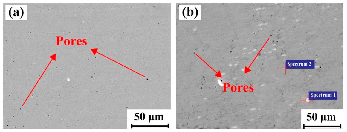
Figure 2 presents the cross-sectional microstructures of the IN625 and IN625-YSZ coatings. Both coatings exhibit a dense structure with sound metallurgical bonding to the substrate, though a limited number of pores are inevitably present. Quantitative image analysis yielded porosities of 1.87% ± 0.15% and 1.67% ± 0.10% for the IN625 and IN625-YSZ coatings, respectively. In LDED coatings, porosity is generally ascribed to shielding gas entrapment or the collapse of transient melt pools during rapid solidification [18]. Notably, the incorporation of YSZ results in a measurable reduction in porosity relative to the monolithic IN625 coating. YSZ particles may provide favorable sites for pit initiation, which promote more uniform solidification, refine the solidification microstructure, and suppress gas entrapment and pore coalescence [19].
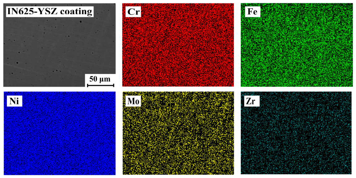
EDS point analyses were conducted on a representative YSZ particle (Spectrum 1) and the surrounding matrix (Spectrum 2) to confirm phase identity. The quantified compositions are listed in Table 3. Spectrum 1 reveals markedly elevated concentrations of Zr (53.08 wt.%) and O (32.11 wt.%), confirming that the bright-contrast phase corresponds to a Zr- and O-rich ceramic constituent consistent with YSZ. Spectrum 2 yields Ni (57.21 wt.%), Cr (17.35 wt.%), Mo (7.57 wt.%), and Fe, in close agreement with the nominal composition of IN625. Figure 3 shows the EDS elemental maps of the IN625-YSZ coating region, revealing a uniform dispersion of YSZ particles within the matrix.
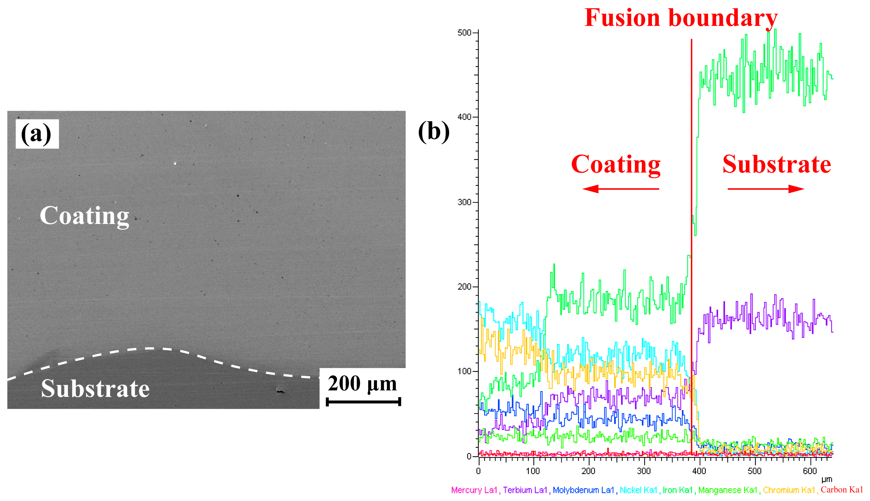
To characterize the elemental transition across the coating-substrate interface, EDS line scanning was performed, as shown in Figure 4. Within the coating region, the Ni, Cr, and Mo signals are consistently elevated while the Fe signal remains low. At the interface, the Fe signal increases sharply, accompanied by a concurrent decline in Ni, Cr, and Mo intensities, indicating an abrupt compositional transition from the coating to the substrate. The dilution ratio (η) was determined following the methodology reported by Ferreira et al. [20], based on the Fe concentration profile across the interface. The calculated dilution ratio is approximately 33%, which falls within the accepted range for nickel-based protective coatings, signifying adequate metallurgical bonding while limiting substrate dilution to an acceptable level.

3.2. Microhardness Distribution

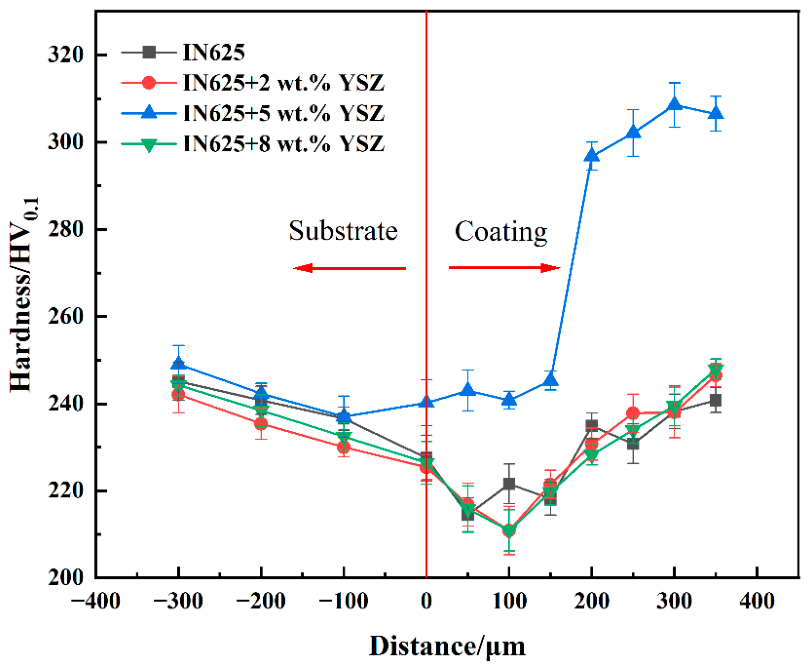
The surface hardness of the IN625-YSZ coating (299.98 HV0.1) is approximately 27.6% higher than that of the IN625 coating (235.01 HV0.1). This may be related to the dispersion strengthening effect of hard YSZ particles, which simultaneously impede dislocation motion and refine the grain structure. The hardness change is related to the phase constitution of the coatings. The γ-Ni matrix, together with hard YSZ particles and Nb-rich Laves phase, contributes to dispersion/precipitation strengthening and dislocation blockage, thereby affecting the microhardness [21,22].
Figure 5 presents the cross-sectional hardness profiles of both coatings. In the heat-affected zone (HAZ) of the substrate, both coatings show a hardness reduction toward the interface, consistent with thermally induced tempering of the 20G steel during deposition [23]. For the IN625-YSZ coating, this decline is partially offset near the interface by rapid heat dissipation into the cold substrate and grain boundary pinning by YSZ particles, resulting in a slight hardness recovery that is absent in the IN625 coating. Within the coating itself, both systems exhibit a localized hardness drop adjacent to the interface, attributed to the tempering and grain coarsening of previously deposited layers induced by subsequent thermal cycles [24,25,26]. Beyond this softened zone, however, the two coatings diverge markedly: the IN625 coating recovers to a stable plateau, whereas the IN625-YSZ coating rises sharply to values exceeding those of the substrate. This confirms that YSZ particles retain their strengthening effect through successive thermal cycles, and that their uniform dispersion within the IN625 matrix governs the superior hardness of the composite coatings in the regions unaffected by interfacial thermal transients.

3.3. Cyclic Polarization Measurements

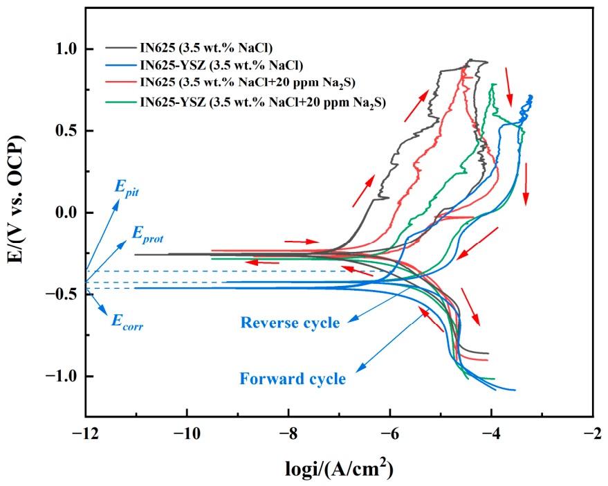
Figure 6 displays the cyclic polarization curves of the IN625 and IN625-YSZ coatings in 3.5% NaCl and 3.5% NaCl + 20 ppm Na2S solutions. The polarization curves of both coatings show a passivation-pitting corrosion behavior. The extracted pitting parameters are summarized in Table 4.
As shown in Figure 6, during the forward scan from cathodic to anodic potentials, Ecorr is defined as the potential at which the anodic and cathodic currents are equal, reflecting the thermodynamic tendency of the system to corrode. As the potential increases further, the current remains at a low passive level until Epit is reached. At Epit, a sharp increase in current indicates breakdown of the passive film and the onset of stable pitting. When the anodic current reaches the preset limit, the scan is reversed. During the reverse scan, the current decreases. If repassivation occurs, the reverse branch intersects the forward anodic branch and the corresponding potential is taken as Eprot. Below Eprot, pit growth can no longer be sustained and the existing pits begin to repassivate [27,28]. The area of the hysteresis loop enclosed by the forward and reverse scans directly reflects the extent of pit propagation and the difficulty of repassivation [29]. The IN625 coating in 3.5 wt.% NaCl solution exhibited negative hysteresis, suggesting that the corrosion sites repassivated readily during the reverse scan. In contrast, the other three samples showed positive hysteresis, indicating that stable pit growth occurred before repassivation. Taking the IN625-YSZ coating in 3.5 wt.% NaCl solution as an example, the characteristic potentials and scan directions are clearly marked.
Table 4 shows that in 3.5 wt.% NaCl solution, the IN625 coating exhibits a relatively noble Epit of −0.10 V, indicating a higher overpotential for pit initiation. However, its Eprot (−0.25 V) is only 0.01 V positive to Ecorr (−0.26 V), suggesting very poor repassivation capability and the largest hysteresis loop, signifying severe pit propagation. With the addition of YSZ, the IN625-YSZ coating shows a negative shift in Ecorr to −0.47 V and a lower Epit of −0.36 V. The separation between Eprot (−0.43 V) and Ecorr widens to 0.04 V, and the hysteresis loop becomes the smallest among all specimens. This demonstrates that YSZ greatly enhances repassivation and self-healing of the passive film, effectively suppressing pit growth even though pitting initiates at a lower potential [30].
In the 3.5 wt.% NaCl + 20 ppm Na2S solution, the IN625 coating suffers a negative shift of Epit to −0.18 V, and Eprot (−0.26 V) almost coincides with Ecorr (−0.27 V), implying promoted pit initiation and persistently poor repassivation. In contrast, the IN625-YSZ coating in the sulfidic medium exhibits a positive shift of Epit to −0.23 V, which is more positive than the value of −0.36 V measured in 3.5 wt.% NaCl solution. This indicates that YSZ effectively raises the resistance to pit initiation in the presence of sulfides. Its Eprot (−0.39 V) and Ecorr (−0.42 V) maintain a difference of 0.03 V. Although the repassivation ability is slightly lower than in 3.5 wt.% NaCl solution, it remains markedly superior to that of the IN625 coating, with a much smaller hysteresis loop. Overall, the incorporation of YSZ shifts the corrosion potential of IN625 negatively and appears to modify the localized corrosion response in a stage-dependent manner. In 3.5 wt.% NaCl without S2−, it markedly reduces the hysteresis loop, suggesting an improved tendency for repassivation. In 3.5 wt.% NaCl + 20 ppm Na2S, it may help suppress pit propagation. This observation may be associated with a partial physical barrier effect of YSZ against aggressive ions and a possible enhancement of passive-film repassivation [31].
In 3.5 wt.% NaCl, the Icorr values of IN625 and IN625-YSZ coatings were 0.088 and 0.121 μA·cm−2, respectively, indicating a slightly higher corrosion rate for the composite coating. After adding 20 ppm Na2S, Icorr increased to 0.417 μA·cm−2 for the IN625 coating and 1.666 μA·cm−2 for the IN625-YSZ coating, corresponding to increases of about 4.7 and 13.8 times, respectively, which suggests that S2− markedly accelerated anodic dissolution and weakened passive film stability, especially for the composite coating. Although Icorr mainly reflects the overall corrosion rate, it also helps reveal the stability of the passive film before pitting occurs. A lower Icorr means slower uniform dissolution and a more protective passive layer, which is beneficial for delaying pit initiation [32].

3.4. EIS Analysis of Pitting Behavior

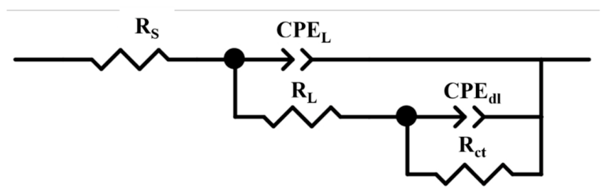
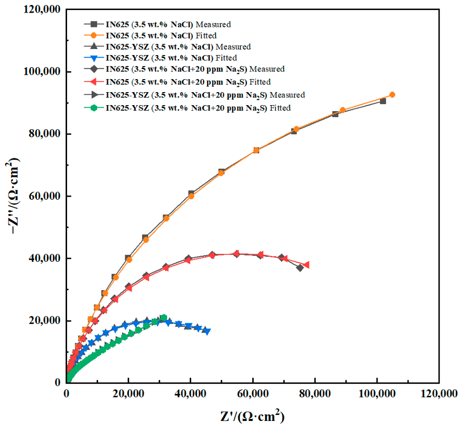
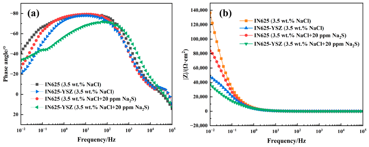
The EIS measurements were performed in different solutions after OCP tests. The results are presented in both Nyquist and Bode plots shown in Figure 7 and Figure 8. The fitting was performed using the equivalent circuit model R(Q(R(QR))) as illustrated in Figure 9, and the fitted parameters are listed in Table 5 [33]. The circuit was selected because two distinct time constants are observed in the Bode phase spectra, suggesting the presence of two electrochemical processes.
The capacitive semicircle diameter reflects the charge transfer resistance and corrosion resistance. A larger diameter indicates a more protective passive film [34]. Figure 7 displays that the diameters decrease in the order of the IN625 coating in 3.5 wt.% NaCl solution, the IN625 coating in S2−-containing solution, the IN625-YSZ coating in 3.5 wt.% NaCl solution, and the IN625-YSZ coating in S2−-containing solution. The IN625 coating in the benign chloride environment exhibits the best barrier property. The IN625 coating in the sulfidic medium still retains a fairly large semicircle, suggesting that S2− causes only moderate degradation. Both YSZ-containing coatings yield smaller diameters. Even the IN625-YSZ coating in 3.5 wt.% NaCl solution shows a diameter smaller than that of the IN625 coating in S2−-containing solution, indicating that YSZ addition reduces the charge transfer resistance. The IN625-YSZ coating in the S2−-containing solution produces the smallest semicircle, corresponding to the poorest corrosion resistance. The combined presence of YSZ and S2− leads to the most severe deterioration of passive film protectiveness.
The equivalent circuit R(Q(R(QR))) contains two-time constants, each composed of a resistance in parallel with a constant phase element (CPE). The CPE is employed to account for the non-ideal capacitive behavior [35]. In this model, RL and CPEL represent the outer porous layer, while Rct and CPEdl correspond to the charge-transfer process at the passive film/electrolyte interface. RS is the solution resistance, which remains nearly constant across all tests [36].
RL reflects the barrier property of the outer layer. In 3.5 wt.% NaCl solution, the IN625-YSZ coating exhibits a slightly higher RL (39,820 Ω·cm2) than IN625 (31,350 Ω·cm2), suggesting that YSZ may lead to a somewhat more resistive outer layer. However, upon addition of S2−, the RL of the IN625-YSZ coating drops drastically to 2.513 Ω·cm2, while that of IN625 increases to 51,280 Ω·cm2. This indicates that the outer layer on the composite coating is severely disrupted by S2− attack, whereas the IN625 coating retains a more stable outer barrier [25,37]. Here, RL mainly represents the resistance of the outer barrier/passive layer, which reflects the protective ability of the coating surface, while Rct is related to the charge-transfer process at the coating/inner passive-layer interface. Therefore, the pronounced decrease in RL suggests that the surface barrier is strongly weakened by sulfide attack, even though the interfacial reaction remains relatively more resistive.
Rct directly reflects the corrosion kinetics at the passive film surface. A higher Rct indicates a slower corrosion rate and better protectiveness. In 3.5 wt.% NaCl solution, the IN625 coating shows a high Rct of 3.267 × 10⁵ Ω·cm2, while the IN625-YSZ coating exhibits a much lower value of 0.2517 × 10⁵ Ω·cm2, indicating that YSZ/matrix interfaces act as preferential pathways for ionic conduction and reduce the protective efficiency of the passive film. In S2−-containing solution, the Rct of IN625 decreases to 0.7425 × 10⁵ Ω·cm2, reflecting moderate film degradation [38]. Notably, the IN625-YSZ coating in sulfidic medium shows an increased Rct of 2.738 × 10⁵ Ω·cm2 compared to its 3.5 wt.% NaCl solution counterpart, which may be related to the formation of S2−-containing corrosion products that partially block active sites and impede charge transfer [39,40]. However, this increase in Rct (from 0.2517 × 10⁵ to 2.738 × 10⁵ Ω·cm2) is not sufficient to offset the pronounced decrease in RL (from 39,820 to 2.513 Ω·cm2), so the coating still exhibits a less protective overall barrier response despite the higher fitted Rct value [41].
The simultaneous sharp reduction in RL and the smallest capacitive semicircle (Figure 6) for the IN625-YSZ coating in S2−-containing solution indicate that the outer layer is heavily damaged. The dramatic decrease in RL after sulfide addition suggests severe degradation of the outer porous/passive layer. Because RL is sensitive to local rupture and electrolyte penetration, sulfide ions may promote film destabilization and pit initiation at YSZ-related interfaces and defects, resulting in the collapse of the outer barrier layer and a pronounced reduction in RL. However, its partially recovered Rct suggests that the charge-transfer process is retarded to some extent. These fitting results are consistent with the CPP findings that the IN625-YSZ coating maintains acceptable repassivation ability even in sulfidic medium.
A higher low-frequency impedance modulus (|Z|) and a larger phase angle normally indicate a more protective passive film [42]. As shown in Figure 8, the maximum |Z| values decrease in the same order as the Nyquist capacitive semicircle diameters. The IN625 coating in 3.5 wt.% NaCl solution gives the highest |Z|, followed by the IN625 coating in the S2−-containing solution, the IN625-YSZ coating in 3.5 wt.% NaCl solution, and the IN625-YSZ coating in the S2−-containing solution. The three coatings other than the IN625-YSZ coating in the sulfidic medium exhibit nearly identical maximum phase angles, implying that these passive films possess a similar capacitive character but differ in ionic resistance. The IN625-YSZ coating in the S2−-containing solution shows the lowest |Z| and a markedly smaller phase angle. This points to a less capacitive and more defective passive film, consistent with its smallest Nyquist diameter. The combination of YSZ and S2− therefore leads to the most severe degradation of passive film protectiveness.

3.5. Pit Morphology and the Role of YSZ

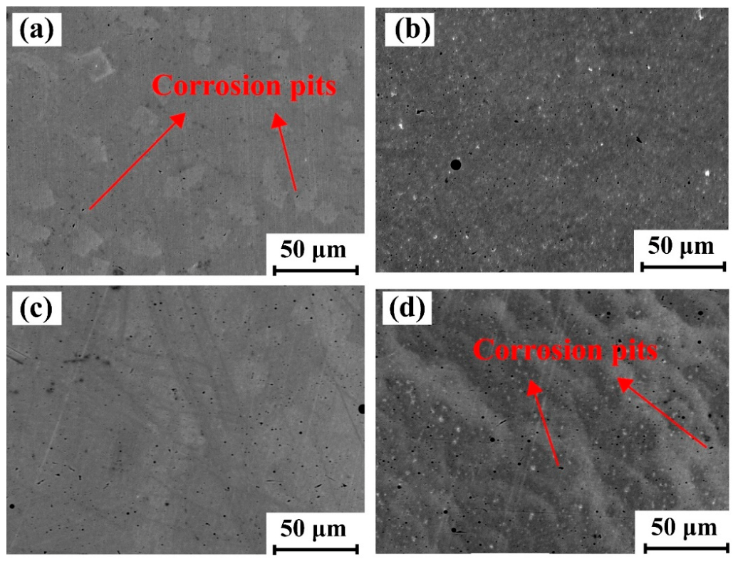
Figure 10 presents the SEM morphologies of the coatings after removal of corrosion products. All pits exhibit sharp and irregular edges with a characteristic water-drop or bowl-like shape. The pitting features correspond well with the EIS and CPP testing results. The IN625 coating in 3.5 wt.% NaCl solution (Figure 10a) shows the fewest pits. Although its noble Epit of −0.10 V indicates difficult pit initiation and the Nyquist plot gives the largest capacitive semicircle, the nearly overlapping Eprot and Ecorr and the largest hysteresis loop point to extremely poor repassivation. Once pits form, they propagate severely, resulting in a small number of relatively deep pits [43]. The IN625 coating in the S2−-containing solution (Figure 10c) displays an increased pit population and larger pit dimensions. The negative shift of Epit promotes pit initiation, while the persistently poor repassivation allows continued growth, consistent with the moderately reduced capacitive semicircle.
The IN625-YSZ coating in 3.5 wt.% NaCl solution (Figure 10b) develops numerous but noticeably shallower and smaller pits. The low Epit of −0.36 V facilitates pit nucleation, yet the widened separation between Eprot and Ecorr and the smallest hysteresis loop confirm that YSZ greatly enhances repassivation and suppresses pit propagation, even though the Nyquist diameter is smaller than that of the IN625 sulfide coating [44,45]. The IN625-YSZ coating in the S2−-containing solution (Figure 10d) suffers the most severe pitting, with a high density of large and deep pits. This observation matches its smallest capacitive semicircle, lowest impedance modulus, and depressed phase angle.

3.6. Discussion on Pitting Mechanism

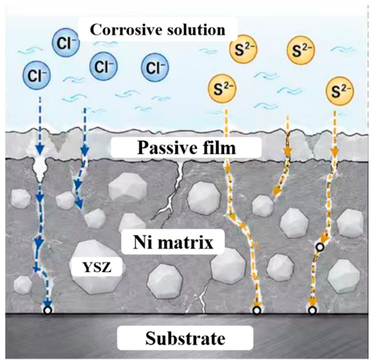
Based on the combined results and the schematic mechanism of Cl and S2− attack (Figure 11), we propose the following pitting mechanism for LDED-manufactured IN625-YSZ coatings:
YSZ addition negatively shifts Epit in 3.5 wt.% NaCl solution (from −0.10 V to −0.36 V). This is attributed to the YSZ/matrix interfaces acting as pit nucleation sites and preferred channels for aggressive ions [46]. As illustrated in the left-hand sequence of Figure 10, Cl ions preferentially penetrate inward through pores, microcracks, and these YSZ/matrix interfaces.
Despite promoting pit initiation, the incorporation of YSZ significantly enhances repassivation. The IN625-YSZ coating exhibits a much smaller hysteresis loop and a wider Eprot-Ecorr separation (0.04 V vs. 0.01 V for IN625 in 3.5 wt.% NaCl solution). While Cl attacks the passive film, the fine grains and uniform dispersion of YSZ facilitate the rapid re-formation of the passive film, effectively inhibiting the development of pits into deep cavities [47,48].
Under S2−-containing conditions, S2− degrades the passive film protectiveness for both coatings, as evidenced by reduced capacitive semicircles and impedance. The presence of S2− introduces an additional and more destructive pathway, illustrated in the right-hand sequence of Figure 10. S2− preferentially accumulates at defects, including YSZ interfaces. These species destabilize the passive film and severely hinder repassivation [49,50].
For the IN625 coating, S2− causes a negative Epit shift and persistently large hysteresis, indicating poor repassivation. For the IN625-YSZ coating, S2− lowers Eprot from −0.43 V to −0.39 V and slightly enlarges the loop. EIS analysis reveals that the synergistic attack of Cl and S2− combined with the abundant YSZ interfaces leads to the most defective passive film for the IN625-YSZ coating in sulfidic medium, resulting in the smallest capacitive semicircle and the lowest impedance modulus (Figure 6). However, repassivation remains superior to that of IN625, with a positive Eprot-Ecorr gap of 0.03 V and no catastrophic loss of passivation.
These findings highlight a trade-off: YSZ addition improves hardness but increases pitting susceptibility, especially in 3.5 wt.% NaCl solution. However, under S2−-containing conditions, the composite coating does not show a catastrophically worse repassivation behavior, which is encouraging for certain marine applications where S2− is present.

4. Conclusions

(1)
Dense IN625 and IN625-YSZ coatings were successfully fabricated on 20G steel by LDED. The addition of 5 wt.% YSZ reduced porosity (from 1.87% ± 0.15% to 1.67% ± 0.10%) and increased microhardness by approximately 27.6%.
(2)
CPP and post-corrosion morphology show that YSZ lowers both Epit and Eprot in 3.5 wt.% NaCl solution, promoting pit initiation at YSZ/matrix interfaces. YSZ significantly enhances repassivation, which is reflected by the smallest hysteresis loop and a wider Eprot-Ecorr gap (0.04 V vs. 0.01 V). S2− degrades the passive film for both coatings, shifting Epit negatively for IN625 to −0.18 V and reducing Eprot for the IN625-YSZ coating to −0.39 V, yet the IN625-YSZ coating retains superior repassivation over IN625 even in sulfidic medium.
(3)
EIS confirms that the combined presence of YSZ and S2− yields the smallest capacitive semicircle and lowest impedance modulus, indicating the most defective passive film. In 3.5 wt.% NaCl solution, the IN625-YSZ coating shows a lower RL of 39,820 Ω·cm2 and Rct of 0.2517 × 10⁵ Ω·cm2 than IN625 (31,350 Ω·cm2 and 3.267 × 10⁵ Ω·cm2, respectively), whereas in 3.5 wt.% NaCl + 20 ppm Na2S solution, RL drops sharply to 2.513 Ω·cm2 and Rct increases to 2.738 × 10⁵ Ω·cm2. However, no catastrophic loss of repassivation occurs for the IN625-YSZ coating.
It should be noted that the proposed mechanism is based on CPP, EIS, and post-corrosion morphology, and was not directly confirmed by surface chemical characterization; therefore, it should be considered as a tentative interpretation.
(4)
These findings highlight a trade-off: YSZ improves hardness but increases pitting susceptibility, especially in 3.5 wt.% NaCl solution. In S2−-containing conditions, the composite maintains acceptable repassivation, suggesting potential for S2−-rich marine applications where wear resistance is a primary concern.

Author Contributions

Writing—original draft, Y.Y.; methodology, Y.Y. and Y.G.; conceptualization, Y.Y. and Y.G.; writing—review and editing, Y.G. and R.L.; funding acquisition, Y.Y. and R.L.; data curation, Y.Y., X.M., L.Y., J.Z. (Jian Zhang 1) and J.Z. (Jian Zhang 2); validation, X.M., L.Y., J.Z. (Jian Zhang 1) and J.Z. (Jian Zhang 2). All authors have read and agreed to the published version of the manuscript.

Funding

This work was supported by the Science and Technology Project of Jiangsu Provincial Administration for Market Regulation (No. KJ2025028) and the Postgraduate Research & Practice Innovation Program of Jiangsu Province.

Data Availability Statement

Data are contained within the article.

Acknowledgments

The authors would like to express their sincere gratitude to JITRI Advanced Materials R&D Co., Ltd. for providing the characterization facilities used in this work.

Conflicts of Interest

The authors declare no conflicts of interest.

References

  1. Shojai, S.; Schaumann, P.; Braun, M.; Ehlers, S. Influence of pitting corrosion on the fatigue strength of offshore steel structures based on 3D surface scans. Int. J. Fatigue 2022, 164, 107128. [Google Scholar] [CrossRef]
  2. Bhandari, J.; Khan, F.; Abbassi, R.; Garaniya, V.; Ojeda, R. Modelling of pitting corrosion in marine and offshore steel structures—A technical review. J. Loss Prev. Proc. 2015, 37, 39–62. [Google Scholar] [CrossRef]
  3. Sazou, D.; Kourouzidou, M.; Pavlidou, E. Potentiodynamic and potentiostatic deposition of polyaniline on stainless steel: Electrochemical and structural studies for a potential application to corrosion control. Electrochim. Acta 2007, 52, 4385–4397. [Google Scholar] [CrossRef]
  4. Alhajji, J.N.; Reda, M.R. The Conflicting Roles of Complexing Agents on the Corrosion of Copper-Nickel Alloys in Sulfide Polluted Seawater. J. Electrochem. Soc. 1994, 141, 1432. [Google Scholar] [CrossRef]
  5. Cao, S.; Zhang, P.; Feng, S.; Zhou, J. Microstructure and High-Temperature Tribological Properties of Nickel-Based Composite Coatings with Laser In Situ Induced TiC and MoSi2 Reinforcement. J. Therm. Spray Technol. 2024, 33, 1006–1026. [Google Scholar] [CrossRef]
  6. Yang, H.; Li, W.; Liu, Y.; Li, F.; Yi, J.; Eckert, J. The Microstructure and Properties of Ni60/60% WC Wear-Resistant Coatings Prepared by Laser-Directed Energy Deposition. Micromachines 2024, 15, 1071. [Google Scholar] [CrossRef] [PubMed]
  7. Liang, J.; Yan, J.; Li, C.; Yang, Y. Comparing Microstructure and Corrosion Performance of Laser Powder Bed Fusion 316L Stainless Steel Reinforced with Varied Ceramic Particles. Metals 2026, 16, 173. [Google Scholar] [CrossRef]
  8. Rossi, E.; Polder, R.; Copuroglu, O.; Nijland, T.; Šavija, B. The influence of defects at the steel/concrete interface for chloride-induced pitting corrosion of naturally-deteriorated 20-years-old specimens studied through X-ray Computed Tomography. Constr. Build. Mater. 2020, 235, 117474. [Google Scholar] [CrossRef]
  9. Praharaj, A.K.; Bontha, S.; Balla, V.K.; Chakrapani, S.K.; Suvin, P.S. Microstructure—Corrosion performance correlation of laser directed energy deposited Inconel 625. J. Alloys Compd. 2025, 1036, 182089. [Google Scholar] [CrossRef]
  10. Long, H.; Li, T.; Shi, H.; Gui, Y.; Qiu, C. Experimental Study of Laser Cladding Ni-Based Coating Based on Response Surface Method. Coatings 2023, 13, 1216. [Google Scholar] [CrossRef]
  11. Garcia, I.; Conde, A.; Langelaan, G.; Fransaer, J.; Celis, J.P. Improved corrosion resistance through microstructural modifications induced by codepositing SiC-particles with electrolytic nickel. Corros. Sci. 2003, 45, 1173–1189. [Google Scholar] [CrossRef]
  12. Shi, J.; Wang, D.; Ming, J.; Sun, W. Passivation and Pitting Corrosion Behavior of a Novel Alloy Steel (00Cr10MoV) in Simulated Concrete Pore Solution. J. Mater. Civ. Eng. 2018, 30, 04018232. [Google Scholar] [CrossRef]
  13. Sherif, E.-S.M. Effects of 5-(3-aminophenyl)-tetrazole on the inhibition of unalloyed iron corrosion in aerated 3.5% sodium chloride solutions as a corrosion inhibitor. Mater. Chem. Phys. 2011, 129, 961–967. [Google Scholar] [CrossRef]
  14. Gola, K.; Ledwig, P.; Dubiel, B. Effect of Microstructure of Additively Manufactured Inconel 625 on Long-Term Corrosion Behaviour in Sulfuric Acid Media. JOM 2023, 75, 1242–1250. [Google Scholar] [CrossRef]
  15. Rezayat, M.; Aboutorabi Sani, A.; Talafi Noghani, M.; Saghafi Yazdi, M.; Taheri, M.; Moghanian, A.; Mohammadi, M.A.; Moradi, M.; Mateo García, A.M.; Besharatloo, H. Effect of Lateral Laser-Cladding Process on the Corrosion Performance of Inconel 625. Metals 2023, 13, 367. [Google Scholar] [CrossRef]
  16. Zeng, X.; Yang, M.; Hu, Q.; Wu, Z.; Xia, D.-H.; Zhang, Y.; Qin, Z.; Li, Q.; Hu, W. Unraveling the corrosion mechanism of Monel K500 in a sulfurous environment: Pitting initiation and propagation. Corros. Sci. 2026, 262, 113664. [Google Scholar] [CrossRef]
  17. Zhao, Y.; Cui, Y.; Hasebe, Y.; Bian, H.; Yamanaka, K.; Aoyagi, K.; Hagisawa, T.; Chiba, A. Controlling factors determining flowability of powders for additive manufacturing: A combined experimental and simulation study. Powder Technol. 2021, 393, 482–493. [Google Scholar] [CrossRef]
  18. Cen, L.; Yang, P.; Jiang, L.; Zhao, S.; Gao, X.; Gao, M. Pore formation mechanisms in laser directed energy deposition of high strength aluminum alloys. J. Manuf. Process. 2025, 152, 126–138. [Google Scholar] [CrossRef]
  19. Ghodsi, M.Z.; Khademzadeh, S.; Marzbanrad, E.; Razmpoosh, M.H.; De Marchi, N.; Toyserkani, E. Development of Yttria-stabilized zirconia reinforced Inconel 625 metal matrix composite by laser powder bed fusion. Mat. Sci. Eng. A 2021, 827, 142037. [Google Scholar] [CrossRef]
  20. Ferreira, A.A.; Amaral, R.L.; Romio, P.C.; Cruz, J.M.; Reis, A.R.; Vieira, M.F. Deposition of Nickel-Based Superalloy Claddings on Low Alloy Structural Steel by Direct Laser Deposition. Metals 2021, 11, 1326. [Google Scholar] [CrossRef]
  21. Savitha, U.; Reddy, G.J.; Singh, V.; Gokhale, A.A.; Sundararaman, M. Additive laser deposition of compositionally graded NiCrAlY-YSZ multi-materials on IN625-NiCrAlY substrate. Mater. Charact. 2020, 164, 110317. [Google Scholar] [CrossRef]
  22. Misra, S.; Nandi, S.; Patra, P.; Mohanty, I.; Saha, P.; Kumar, C.S. Influence of ultrasonic vibration on microstructure, texture and mechanical characteristics of Inconel 625 additively manufactured through continuous and pulsed laser directed energy deposition. Mater. Charact. 2025, 229, 115504. [Google Scholar] [CrossRef]
  23. Khan, M.S.; Soleimani, M.; Midawi, A.R.H.; Aderibigbe, I.; Zhou, Y.N.; Biro, E. A review on heat affected zone softening of dual-phase steels during laser welding. J. Manuf. Process. 2023, 102, 663–684. [Google Scholar] [CrossRef]
  24. Rao, H.; Oleksak, R.P.; Favara, K.; Harooni, A.; Dutta, B.; Maurice, D. Behavior of yttria-stabilized zirconia (YSZ) during laser direct energy deposition of an Inconel 625-YSZ cermet. Addit. Manuf. 2020, 31, 100932. [Google Scholar] [CrossRef]
  25. Likhwar, J.; Thanumoorthy, R.S.; Bontha, S.; Balan, A.S.S. Evaluation of functionally graded YSZ-IN625 clad without bond coat using laser directed energy deposition. Mater. Lett. 2023, 351, 135012. [Google Scholar] [CrossRef]
  26. Lima, R.S.; Guerreiro, B.M.H.; Aghasibeig, M. Microstructural Characterization and Room-Temperature Erosion Behavior of As-Deposited SPS, EB-PVD and APS YSZ-Based TBCs. J. Therm. Spray Technol. 2019, 28, 223–232. [Google Scholar] [CrossRef]
  27. Esmailzadeh, S.; Aliofkhazraei, M.; Sarlak, H. Interpretation of Cyclic Potentiodynamic Polarization Test Results for Study of Corrosion Behavior of Metals: A Review. Prot. Met. Phys. Chem. Surf. 2018, 54, 976–989. [Google Scholar] [CrossRef]
  28. Bellezze, T.; Viceré, A.; Giuliani, G.; Sorrentino, E.; Roventi, G. Study of Localized Corrosion of AISI 430 and AISI 304 Batches Having Different Roughness. Metals 2018, 8, 244. [Google Scholar] [CrossRef]
  29. Ma, J.; Wen, J.; Li, Q.; Zhang, Q. Electrochemical polarization and corrosion behavior of Al-Zn-In based alloy in acidity and alkalinity solutions. Int. J. Hydrogen Energy 2013, 38, 14896–14902. [Google Scholar] [CrossRef]
  30. Koch, D.; Mack, D.E.; Vaßen, R. Degradation and lifetime of self-healing thermal barrier coatings containing MoSi2 as self-healing particles in thermo-cycling testing. Surf. Coat. Technol. 2022, 437, 128353. [Google Scholar] [CrossRef]
  31. Ziegler, C.; Frank, G.; Göpel, W. Interface Properties of Thin YBa2Cu3O7−x Films. Berichte Bunsenges. Phys. Chem. 1991, 95, 1404–1409. [Google Scholar] [CrossRef]
  32. Barkat, F.; Mukhtar, A.; Afzal, M.; Arshad, S.; Arshad, S.; Cheng, S.; Hu, C.; Wu, K. Effect of calcium addition on inclusion refinement, passive film chemistry and pitting corrosion resistance of S30403 austenitic stainless steel. J. Mater. Res. Technol. 2026, 42, 6552–6563. [Google Scholar] [CrossRef]
  33. Bredar, A.R.C.; Chown, A.L.; Burton, A.R.; Farnum, B.H. Electrochemical Impedance Spectroscopy of Metal Oxide Electrodes for Energy Applications. ACS Appl. Energy Mater. 2020, 3, 66–98. [Google Scholar] [CrossRef]
  34. Lee, K.-K.; Kim, K.-B. Electrochemical impedance characteristics of pure Al and Al-Sn alloys in NaOH solution. Corros. Sci. 2001, 43, 561–575. [Google Scholar] [CrossRef]
  35. Rondelli, G.; Torricelli, P.; Fini, M.; Giardino, R. In vitro corrosion study by EIS of a nickel-free stainless steel for orthopaedic applications. Biomaterials 2005, 26, 739–744. [Google Scholar] [CrossRef] [PubMed]
  36. Mao, F.; Dong, C.; Macdonald, D.D. Effect of octadecylamine on the corrosion behavior of Type 316SS in acetate buffer. Corros. Sci. 2015, 98, 192–200. [Google Scholar] [CrossRef]
  37. Mukhopadhyay, A.; Sahoo, S. Corrosion protection of reinforcement steel rebars by the application of electroless nickel coatings. Eng. Res. Express 2019, 1, 015021. [Google Scholar] [CrossRef]
  38. Mandal, S.; Singh, J.K.; Mallapur, S.; Lee, D.-E.; Park, T. Effect of triethanolamine and sodium hexametaphosphate on formation, growth and breakdown of passive layer in concrete pore solution. J. Build. Eng. 2022, 59, 105113. [Google Scholar] [CrossRef]
  39. Chen, J.-C.; Liu, C.-Y. Effects of different pollutants on the performance and deactivation of Pt-Pd catalysts in a pilot-scale waste incineration system. Combust. Sci. Technol. 2018, 190, 1971–1987. [Google Scholar] [CrossRef]
  40. Salvarezza, R.C.; Videla, H.A.; Arvía, A.J. The electrodissolution and passivation of mild steel in alkaline sulphide solutions. Corros. Sci. 1982, 22, 815–829. [Google Scholar] [CrossRef]
  41. Lewis, K.J.; Aklian, J.H.; Sharaby, A.; Zook, J.D. Quantitative methods of predicting relative effectiveness of corrosion inhibitive coatings. Aircr. Eng. Aerosp. Technol. 1996, 68, 12–22. [Google Scholar] [CrossRef]
  42. Fang, R.; Liu, R.; Xie, Z.-H.; Wu, L.; Ouyang, Y.; Li, M. Corrosion-resistant and superhydrophobic nickel-phosphorus/nickel/PFDTMS triple-layer coating on magnesium alloy. Surf. Coat. Technol. 2022, 432, 128054. [Google Scholar] [CrossRef]
  43. Brunner, J.G.; May, J.; Höppel, H.W.; Göken, M.; Virtanen, S. Localized corrosion of ultrafine-grained Al-Mg model alloys. Electrochim. Acta 2010, 55, 1966–1970. [Google Scholar] [CrossRef]
  44. Guo, L.; Zheng, H.; Liu, S.; Li, Y.; Feng, C.; Xu, X. Effect of Heat Treatment Temperatures on Microstructure and Corrosion Properties of Inconel 625 Weld Overlay Deposited by PTIG. Int. J. Electrochem. Sci. 2016, 11, 5507–5519. [Google Scholar] [CrossRef]
  45. Lourenço, M.J.C.; Jorge, J.C.F.; de Souza, L.F.G.; Mendes, M.C.; Farneze, H.N.; Araújo, L.S. Microstructure evolution, hardness response, and corrosion resistance of Inconel 625 weld overlay obtained by the ESSC process after post-welding heat treatments. Int. J. Adv. Manuf. Technol. 2023, 127, 3357–3369. [Google Scholar] [CrossRef]
  46. Ryu, H.-S.; Lim, T.-S.; Ryu, J.; Park, D.-S.; Hong, S.-H. Electrochemical Corrosion Properties of YSZ Coated AA1050 Aluminium Alloys Prepared by Aerosol Deposition. J. Korean Ceram. Soc. 2011, 48, 439–446. [Google Scholar] [CrossRef]
  47. Tran, N.; Tada, E.; Nishikata, A. Pit Initiation and Repassivation of Stainless Steels Exposed to Cyclic Relative Humidity Changes. J. Electrochem. Soc. 2015, 162, C419–C425. [Google Scholar] [CrossRef]
  48. Dawson, J.L.; Ferreira, M.G.S. Electrochemical studies of the pitting of austenitic stainless steel. Corros. Sci. 1986, 26, 1009–1026. [Google Scholar] [CrossRef]
  49. Wang, Z.; Zhang, L.; Tang, X.; Zhang, Z.; Lu, M. The surface characterization and passive behavior of Type 316L stainless steel in H2S-containing conditions. Appl. Surf. Sci. 2017, 423, 457–464. [Google Scholar] [CrossRef]
  50. Wu, S.; Wang, J.; Song, S.; Xia, D.-H.; Zhang, Z.; Gao, Z.; Wang, J.; Jin, W.; Hu, W. Factors Influencing Passivity Breakdown on UNS N08800 in Neutral Chloride and Thiosulfate Solutions. J. Electrochem. Soc. 2017, 164, C94. [Google Scholar] [CrossRef]
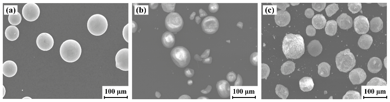
Figure 1. The morphologies of the feedstock powders: (a) IN625; (b) YSZ; (c) IN625+YSZ.
Coatings 16 00929 g001
Figure 2. Cross-sectional microstructures of the coatings: (a) IN625; (b) IN625-YSZ.
Coatings 16 00929 g002
Figure 3. EDS elemental maps of the IN625-YSZ coating.
Coatings 16 00929 g003
Figure 4. EDS line-scanning profile of the IN625-YSZ coating: (a) Cross-sectional micrograph; (b) Elemental concentration profiles across the interface.
Coatings 16 00929 g004
Figure 5. Cross-sectional hardness distribution curves of the IN625 and IN625-YSZ coatings.
Coatings 16 00929 g005
Figure 6. Cyclic polarization curves of the IN625 and IN625-YSZ coatings in different solutions. The arrows indicate the scanning direction.
Coatings 16 00929 g006
Figure 7. Nyquist plots of the IN625 and IN625-YSZ coatings in different solutions.
Coatings 16 00929 g007
Figure 8. Bode plots of the IN625 and IN625-YSZ coatings in different solutions: (a) Bode phase plot; (b) Bode magnitude plot.
Coatings 16 00929 g008
Figure 9. Equivalent circuit model: R(Q(R(QR))).
Coatings 16 00929 g009
Figure 10. Pit morphology and distribution: (a,b) IN625 and IN625-YSZ coatings in 3.5 wt.% NaCl solution respectively; (c,d) IN625 and IN625-YSZ coatings in 3.5 wt.% NaCl + 20 ppm Na2S solution respectively.
Coatings 16 00929 g010
Figure 11. Schematic diagram of the corrosion mechanism of Cl and S2− on IN625-YSZ coatings.
Coatings 16 00929 g011
Table 1. Nominal compositions of IN625 and YSZ powders (wt.%).
MaterialCrMoNbFeNiZrO2 (+HfO2)Y2O3Al2O3SiO2Fe2O3
IN62520–238–103.15–4.15≤5.0Bal./////
YSZ/////91.58.8≤0.002≤0.001≤0.003
Table 2. Nominal composition of 20G steel substrate (wt.%).
MaterialCSiMnPSFe
20G0.17–0.230.17–0.370.35–0.65≤0.025≤0.015Bal.
Table 3. The elemental compositions of the coatings (wt.%).
SpectrumCOCrFeNiZrAlTiMo
Spectrum 132.112.741.623.8853.082.254.32
Spectrum 25.6817.3512.1957.217.57
Table 4. The pitting parameters of the IN625 and IN625-YSZ coatings in different solutions.
Corrosive SolutionCoatingsEOCP (V vs. SCE)Epit/(V vs. OCP)Eprot/(V vs. OCP)Ecorr/(V vs. OCP)Icorr/(μA·cm−2)
3.5 wt.% NaClIN625−0.267−0.10−0.25−0.260.088
IN625-YSZ−0.245−0.36−0.43−0.470.121
3.5 wt.% NaCl +
20 ppm Na2S
IN625−0.273−0.18−0.26−0.270.417
IN625-YSZ−0.325−0.23−0.39−0.421.666
Table 5. EIS fitting parameters for the IN625 and IN625-YSZ coatings in different solutions.
Corrosive SolutionCoatingsRS
(Ω·cm2)
Rs (Err)/%CPELRL
(Ω·cm2)
RL (Err)/%CPEdlRctRct (Err)/%
Y/10−5 S·sn)nY/(10−5 S·sn)n(105Ω·cm2)
3.5 wt.% NaClIN6257.2811.563.4280.90331,35018.71.1430.51013.26720.29
IN625-YSZ7.4201.455.3230.871439,82019.7222.30.65830.251711.24
3.5 wt.% NaCl +
20 ppm Na2S
IN6257.6731.354.7000.891451,28015.402.4720.44860.742517.25
IN625-YSZ7.4831.732.6800.87352.51311.236.2910.38542.73812.38
Disclaimer/Publisher’s Note: The statements, opinions and data contained in all publications are solely those of the individual author(s) and contributor(s) and not of MDPI and/or the editor(s). MDPI and/or the editor(s) disclaim responsibility for any injury to people or property resulting from any ideas, methods, instructions or products referred to in the content.