Article

Crystalline Corundum-Structured Oxides as a Potential Alternative for Mirror Coatings of Gravitational Wave Interferometers

1
Department of Physics and Astronomy, Katholieke Universiteit Leuven, B-3001 Leuven, Belgium
2
Laboratoire des Matériaux Avancés-IP2I, CNRS, Université Claude Bernard Lyon 1, F-69622 Villeurbanne, France
3
Maastricht University, Minderbroedersberg 4-6, 6211 LK Maastricht, The Netherlands
4
Nikhef, Science Park 105, 1098 XG Amsterdam, The Netherlands
5
Department of Materials Engineering, Katholieke Universiteit Leuven, B-3001 Leuven, Belgium
6
Institut des Nanotechnologies de Lyon (INL UMR 5270), Site DOUA Bâtiment Irène JOLIOT CURIE-RDC, 69622 Villeurbanne, France
7
Université de Lyon, Université Claude Bernard Lyon 1, F-69622 Villeurbanne, France
*
Author to whom correspondence should be addressed.
Coatings 2026, 16(8), 895; https://doi.org/10.3390/coatings16080895
Submission received: 25 May 2026 / Revised: 20 July 2026 / Accepted: 20 July 2026 / Published: 27 July 2026
(This article belongs to the Section High-Energy Beam Surface Engineering and Coatings)

Abstract

Crystalline coatings have emerged as a promising alternative to amorphous mirror coatings for planned upgrades of second-generation detectors such as Advanced Virgo and for future 3G observatories. In this work, we investigate the structural and mechanical properties of epitaxial Cr2O3 thin films grown on c-plane sapphire by molecular beam epitaxy, with the objective of evaluating corundum-structured oxides as a new class of crystalline coating materials for gravitational wave interferometers. We report, for the first time, cryogenic mechanical loss measurements of Cr2O3 coatings and relate the measured dissipation to their crystalline quality. The structural and mechanical properties of the coatings were evaluated by XRD, RHEED, AFM, and GeNS measurements. Our findings show that the highest-quality chromia layers exhibit mechanical losses at 6 K as low as ( 5 ± 1 ) × 10−6 rad, while poorer crystalline quality is associated with significantly higher losses. These results demonstrate the potential of corundum-structured oxides as mirror coatings for next-generation interferometers. The wide availability of corundum-structured oxides (X2O3 with X = Al, Ga, Fe, V, Cr, Ti, …) and their epitaxial compatibility with sapphire, including the possibility of forming solid solutions, further highlights the potential of this largely unexplored materials class.

1. Introduction

Second-generation interferometric gravitational wave detectors (GWDs) [1] such as Advanced Virgo (AdV) [2,3] and Advanced LIGO (aLIGO) [4,5] are currently undergoing major upgrades. Advanced Virgo Plus (AdV+), for instance, targets a three-fold improvement in strain sensitivity around 40–400 Hz by increasing the beam and mirror size, providing better quantum noise suppression and installing larger, modified payloads and super-attenuators [6]. At the same time, conceptual designs for third-generation (3G) detectors such as the underground Einstein Telescope (ET) [7,8] aim at an additional order of magnitude leap in sensitivity by combining 10 km cryogenic interferometers with additional noise mitigation strategies. ET will presumably have a so-called xylophone arrangement, employing two separate interferometers per detector. One, ET-HF, will work at high frequency (30 Hz to 10 kHz), high laser power and 290 K (room temperature) similar to current 2G detectors, and a second one, ET-LF, will work in parallel at cryogenic temperature (10 K) and low power to maximize sensitivity in the low frequency regime (1.5 Hz to 30 Hz) [8]. Both interferometers, and by extension also the improved versions of 2G detectors, currently face the same technical bottleneck: the thermal noise in the high-reflectivity mirror coatings, which dominates the mid-band (≈50–300 Hz) noise budget [9]. To lower the magnitude of this noise term, a series of distinct modifications can be implemented, such as operating at cryogenic temperature or reducing the internal friction losses within the coating [10]. Currently, for aLIGO and AdV, the coating chosen for the Fabry–Perot cavity input (ITM) and end (ETM) test mirrors consists of a multilayer stack periodically alternating between a low refractive index (SiO2) and a high refractive index (Ti:Ta2O5) material deposited on an ultrapure heavy (40 kg) silica test mass [11]. Nonetheless, for operations at cryogenic temperature, multilayer coatings of SiO2/Ti:Ta2O5 are not suitable anymore, as the internal mechanical losses of these two amorphous structures tend to increase substantially below 50 K [12,13,14]. Therefore, a wide search for promising candidate materials to employ in the multilayer and as substrate test mass at cryogenic temperatures has started. While the debate on which material should be employed for the test masses is ongoing (silicon and sapphire being the best candidates to replace silica at cryogenic temperatures [15]), the even more critical challenge posed by the coating material is the object of a strenuous research effort.
Crystalline coatings have been proposed as a feasible alternative to the currently used amorphous layers. This consideration stems from a significantly lower structural density of defects, that makes their mechanical losses and optical absorption theoretically orders of magnitude lower than amorphous ones at cryogenic temperatures [16]. Still, their deposition on large scales poses considerable practical challenges, such as obtaining a virtually defect-free well-ordered epitaxial process (crystal growth in which the film adopts the crystallographic orientation of the underlying substrate). It also yields novel concerns related to lattice parameters matching and structural birefringence (in addition to the stress-induced one). One of the most relevant and promising combination of crystalline materials proposed is GaAs/Al0.92Ga0.08As (AlGaAs in short), grown on GaAs ultrapure substrates [17]. Thanks to its wide use in commercially used optical devices [18], the purity of this pair of materials have been refined over the years. This led to the deposition of GaAs/AlGaAs multilayers with extremely low optical absorption (around 3 ppm) [19,20] and mechanical losses at cryogenic temperatures (4.5 × 10⁻⁶ rad) [21]. The main concern with this class of materials is the scalability of its GaAs substrates, currently limited to around 20 cm, to the size of future GWDs mirrors (⌀55 cm [6]).
Corundum-structured oxide coatings (X2O3 compounds where X = Al, Cr, Fe, Ga, Ti, V…), a class of crystalline materials so far unexplored in the GWD field, are of particular interest, owing to the attractive properties of the corundum crystal structure, exemplified by sapphire ( α -Al2O3) [22]. These include trigonal crystal symmetry (hence, a different theoretical defect density), high thermal conductivity, high refractive index and epitaxial compatibility with sapphire substrates. In the particular case of chromia, Cr2O3, which is the focus of this work, this materials platform is further complemented by exceptionally low mechanical losses. Chromia was selected as a model material because of the thermodynamic stability of its sesquioxide phase over a wide range of temperature and pressure conditions [23,24], facilitating reproducible growth, its high refractive index [25] (2.4, suitable as a high-index material), and the ease of epitaxy on polished sapphire substrates, without the need for buffer layers to promote single-crystal growth [26,27,28,29]. In this paper, we present a preliminary structural and mechanical characterization of two Cr2O3 coatings deposited on c-plane sapphire substrates, exhibiting markedly different levels of crystalline quality. The two samples, hereafter referred to as Sample A and Sample B, were selected from a broader experimental campaign aimed at growing high-quality Cr2O3 coatings with low defect density and low mechanical and optical losses. They were selected to represent two distinct levels of crystalline quality achieved during the optimization process and enable an initial comparison of the mechanical losses of corundum-structured coatings. While the limited number of samples does not allow for the individual effects of substrate preparation and deposition parameters to be independently assessed, the present comparison serves as an initial assessment of the relationship between crystalline quality and mechanical dissipation. The primary objective of this work is to report, for the first time, mechanical loss measurements for Cr2O3 crystalline coatings and to establish an experimental foundation for future systematic investigations of corundum-structured oxide coatings. For Sample A, the best-quality epitaxial sample, we measured a loss angle as low as ( 5 ± 1 ) × 10−6 rad around 6 K. These findings suggest a realistic opportunity to further improve the film quality through systematic optimization of the molecular beam epitaxy (MBE) growth conditions. Importantly, a broad range of other corundum-structured oxides, epitaxially compatible with sapphire, can also be grown using this approach, offering encouraging prospects for identifying a material or solid solution ((AxB1−x)2O3) that fully meets the demanding requirements of upgraded second- and third-generation GWDs [30,31].

2. Methods

Prior to deposition, the mechanical losses of bare c-plane sapphire substrates (⌀ 2 ), 430 μm thick (Siegert Wafer) were measured at Laboratoire des Matériaux Avancés (LMA). The sapphire substrates nominally did not have any miscuts, i.e., the surface orientation was off from the ideal (0001) by less than 0.2°, did not have a flat side and were double side polished (roughness lower than 0.3 nm for both surfaces). Before executing the loss angle measurement on the uncoated substrates, the samples were thoroughly cleaned with isopropyl alcohol and de-ionized water. As reported in Table 1, one of the two substrates (later Sample B) was pre-annealed at 900 °C for 24 h in ambient conditions whereas the other substrate (Sample A) did not undergo any heating treatment.
After quantifying the mechanical losses at low temperature (6–65 K), the samples were prepared for deposition at KU Leuven. No further substrate cleaning was performed prior to deposition. Oxygen-assisted MBE was employed to grow crystalline Cr2O3 coatings. The growth conditions and parameters used are reported in Table 1. The base pressure in the chamber was 10−10 Torr. Chromium pellets (Alfa Aesar, 99.995% purity) were heated in an effusion cell until a steady metallic deposition rate of 0.1 Å/s was achieved, which was measured in situ using a quartz crystal microbalance (QCM). To obtain the desired oxide stoichiometry, molecular oxygen was introduced in the chamber. The deposition rate was monitored also during growth via the QCM, calibrated to the molecular weight of Cr2O3.

3. Characterization

3.1. Crystallography

The surface crystallinity of the coatings was assessed preliminarily in situ via reflection high-energy electron diffraction (RHEED). All other characterizations were performed ex situ. The phase and crystallinity of each sample was investigated by X-ray diffraction (XRD) in a Panalytical X’pert Pro diffractometer equipped with a monochromated Cu Kα1 source ( λ = 1.5418 Å). Grazing incidence XRD (GIXRD) scans were performed by keeping ω fixed at 2° and varying θ . The theoretical VESTA powder diffraction pattern of Cr2O3 used as reference was obtained from ref. [32]. Moreover, ω -2 θ symmetric scans were conducted by working in ω = θ condition. Rocking curve (RC) XRD measurements were taken around the (0006) peak of Cr2O3 and Al2O3. 2D reciprocal space maps (RSMs) were obtained by sweeping ω while performing different θ - 2 θ scans centered around the (10110) crystallographic peak of the two materials (substrate-film) under investigation. The surface topography was assessed by atomic force microscopy (AFM; Park XE-100AFM). The AFM images were collected in non-contact mode using Si probes. Image processing and surface roughness determination was performed with the open-source Gwyddion software (version 2.65) [33].

3.2. Coating Loss Angle

The loss angle φ c of the coating samples was estimated by measuring the frequency f and ring-down time τ of the sapphire disks before and after coating deposition, according to
φ c = φ + ( D 1 ) φ 0 D ,
where φ 0 = ( π f 0 τ 0 ) 1 and φ = ( π f τ ) 1 are the disk loss angle before and after coating deposition, respectively. D is a measured, frequency-dependent dilution factor [34], adjusted to take into account the geometry of these samples, where a thin (1.04 mm wide) circular crown adjacent to the border of the wafer was not coated due to masking by the mounting mechanism.
In order to avoid systematic damping from suspension and ambient pressure, we used a clamp-free, in-vacuum gentle nodal suspension (GeNS) system [35] adapted to low-temperature measurements [36]. More details about our experimental setup and data analysis method can be found in earlier studies [11,37]. We measured resonances at 1.8 and 4.2 kHz, in the 6–65 K temperature range. Those frequencies fall within the detection band of ground-based gravitational-wave interferometers (0.01–10 kHz), and that temperature range includes the planned operating temperature of the future ET detector [8].

4. Results

4.1. Structure and Defects

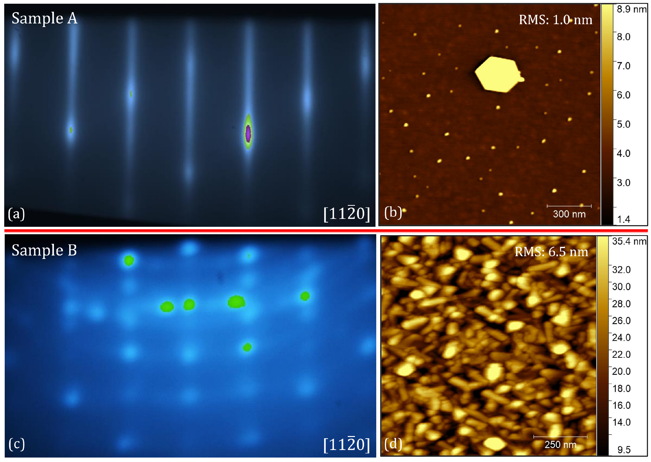
The main structural differences between the Cr2O3-coated sapphire substrates labeled Sample A and Sample B are illustrated in Figure 1. A striking difference in the RHEED pattern and AFM morphology exists between the two films. For Sample A (Figure 1a,b) a smooth epitaxial growth can be concluded: the RHEED pattern shows clear parallel streaks indicating an almost ideally flat surface and a layer-by-layer growth, where atoms complete one atomic layer before the next begins, producing smoother films. The AFM image, in Figure 1b, demonstrates that the Cr2O3 epitaxial film exhibits on its surface some sporadic hexagonal epitaxial islands, around 300 nm in lateral size and 10 nm high, plus a series of smaller localized spots, between 1 and 6 nm in height. These three-dimensional features atop the flat epitaxial lattice, induce the appearance of an overlapping faint trigonal diffraction pattern in RHEED. An RMS roughness of 1.0 nm was found for Sample A, averaging between center and edge measurements. On the other hand, Sample B (Figure 1c,d) shows a mixed epitaxial–polycrystalline deposition process. The RHEED pattern shown in Figure 1c depicts both circular rings and a dotted diffraction pattern, hinting at the presence of several domains either following the substrate order or randomly oriented. This is confirmed by the AFM image in Figure 1d, where a high RMS roughness of 6.5 nm and several domains can be clearly observed.
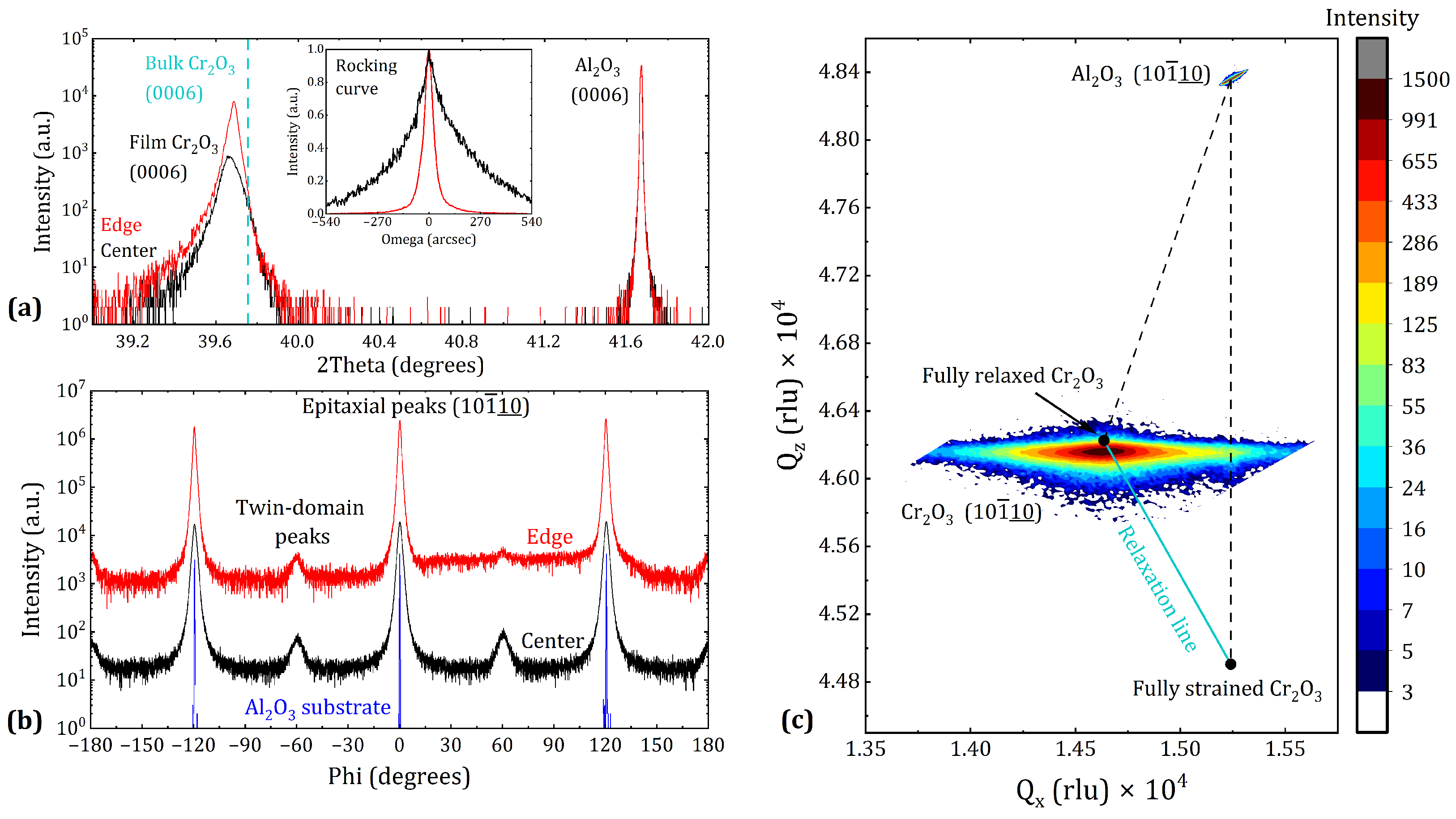
The epitaxial quality of Sample A was evaluated with XRD measurements, shown in Figure 2. The epitaxy of Cr2O3 on the Al2O3 substrate can be clearly confirmed by the θ -2 θ scan in Figure 2a, which illustrates the (0006) peak of both the film and substrate. In the figure, the signal from both the center region (black) and the edge region (located 19 mm from the center, red) of the 2 sample can be observed. The Cr2O3 (0006) peak exhibits a distinct asymmetric profile with a broad tail extending toward lower 2 θ values (corresponding to larger c-axis spacings). This asymmetry arises from a pronounced strain gradient within the coating, where the lattice parameters gradually evolve from a coherent state, where the film shares the substrate’s in-plane lattice parameter, toward their bulk values [38]. In Cr2O3, this gradual unit cell adjustment is mediated by the formation of threading dislocations and twin boundaries that propagate along the film growth direction [39]. Threading dislocations represent line defects that extend from the film/substrate interface toward the surface and relieve lattice mismatch strain, while twin boundaries are regions where the crystal adopts a mirrored crystallographic orientation relative to the surrounding lattice. The center and edge regions of Sample A exhibit tensile out-of-plane strains of 0.22% and 0.17%, respectively, given the shift of the XRD peak position compared to the theoretical bulk value represented by the dotted line. This indicates that the crystal structure of the coating in the peripheral region has relaxed more toward bulk values compared to the center.
In the inset of Figure 2a, the RC diffractograms around the (0006) reflection of Cr2O3 for both the center and edge regions of sample A are presented. The rocking curve measures the spread of crystal orientations around the ideal alignment. A narrower full width at half maximum (FWHM) corresponds to better crystalline alignment and lower defect density. The RC intensity was normalized between 0 and 1 and the corresponding ω angle was shifted to position the peak at 0 degrees in order to optimize the visual comparison between the samples. The RC peak for the center region exhibits a full width at half maximum (FWHM) of 278 arcsec, whereas the edge region presents a much narrower FWHM of 57 arcsec. Since the FWHM reflects the epitaxial growth quality and the density of defects and imperfections in the film area probed by the X-ray beam, these results confirm a significant gradient in the epitaxial growth quality across the sample. The information gained with θ -2 θ and RC scan show that the center region is considerably more strained and has greater mosaicity (broader crystal orientation distribution) than the edge region. This significant difference is most likely due to the impact of the deposition temperature, which is higher at the edge and lower at the center due to the support holder design, enhancing growth by providing the atoms with additional energy to rearrange and minimize the epitaxial stress. More information on the temperature uniformity and gradient in Sample A during growth is shown in Figure S2 in the Supplementary Material, reporting the results of a detailed simulation performed with the COMSOL Multiphysics software version 6.1 [40].
Figure 2b illustrates the ϕ scan around the (10110) reflection of Al2O3 and Cr2O3 for both the center and edge regions of Sample A. The sapphire substrate signal (blue) exhibits a clear threefold symmetry, as expected from its corundum structure. The epitaxial growth of the Cr2O3 film is confirmed by the presence of three intense peaks, separated by 120° and aligned with the substrate peaks, in both the center (black curve) and edge (red curve) regions. In addition to this main epitaxial threefold signal, a triplet of secondary, faint peaks is observed, each shifted by 60° relative to the primary peaks. These three peaks, also separated by 120°, originate from the formation of twin domains within the film. In these nanometric columnar domains, the Cr2O3 structure is rotated by 180° relative to the main epitaxial orientation, rather than aligning precisely with the substrate’s atomic arrangement. This type of three-dimensional defect is common in Cr2O3 [39,41,42], and it usually indicates that either the deposition temperature was not high enough to promote a sufficient surface mobility of the adatoms, or the chosen deposition rate was too high. Nonetheless, also for this measurement, it can be seen that the growth in the edge region was achieved with higher crystalline quality and order, as the individual peaks relative to the main epitaxial orientation (at −120°, 0° and 120°) are narrower than the ones attributed to the center region. Moreover, the ϕ scan peaks attributed to twin domains (at −180°, −60° and 60°) for the edge region show a lower intensity compared to the ones of the center, confirming a lower density of defects.
An RSM measurement around the (10110) reflection of Al2O3 and Cr2O3 of the edge region of Sample A is shown in Figure 2c. Reciprocal space mapping (RSM) is an XRD technique that simultaneously probes the in-plane and out-of-plane lattice parameters, allowing strain and relaxation to be evaluated. The intensity of the 2D-XRD peaks is displayed on a logarithmic scale. The relaxation line (in red), connecting the RSM position of a fully strained pseudomorphic Cr2O3 film with the fully relaxed Cr2O3 bulk film, was used to determine the film peak position. The strain relaxation refers here to the gradual recovery of the film lattice toward its natural bulk lattice parameters after initially matching those of the substrate. The Qx and Qz coordinates, representing the reciprocal in-plane and out-of-plane axis, of the (10110) Cr2O3 peak suggest a compressive in-plane strain of −0.20% and a tensile out-of-plane strain equal to 0.14% in the edge region of Sample A. This agrees well with the out-of-plane strain obtained with the θ - 2 θ measurement around the (0006) XRD peak, equal to 0.17%. Also, the film peak position along the relaxation line reveals a degree of relaxation of 95 % , indicating almost complete relaxation. Observing the shape of the film RSM peak yields further important details. The RSM reflection has a clear asymmetrical shape, more elongated along the Qx direction than along Qz. This asymmetry is most likely caused by the presence of multiple threading dislocations, which propagate from the interface to the surface, limiting the in-plane long-range order of the lattice and elongating the reciprocal lattice point along Qx. Furthermore, a coherent feature can be observed in the film peak at the same Qx coordinate as the sapphire peak: this small vertical stretching of the peak is due to the coherent part of the film, present at the interface with the substrate, where the film contracts and takes the same in-plane lattice parameters as the substrate (feature occurring along the vertical dashed line), hence making the spacing in the out-of-plane direction larger than bulk, as expected given the positive Poisson ratio.
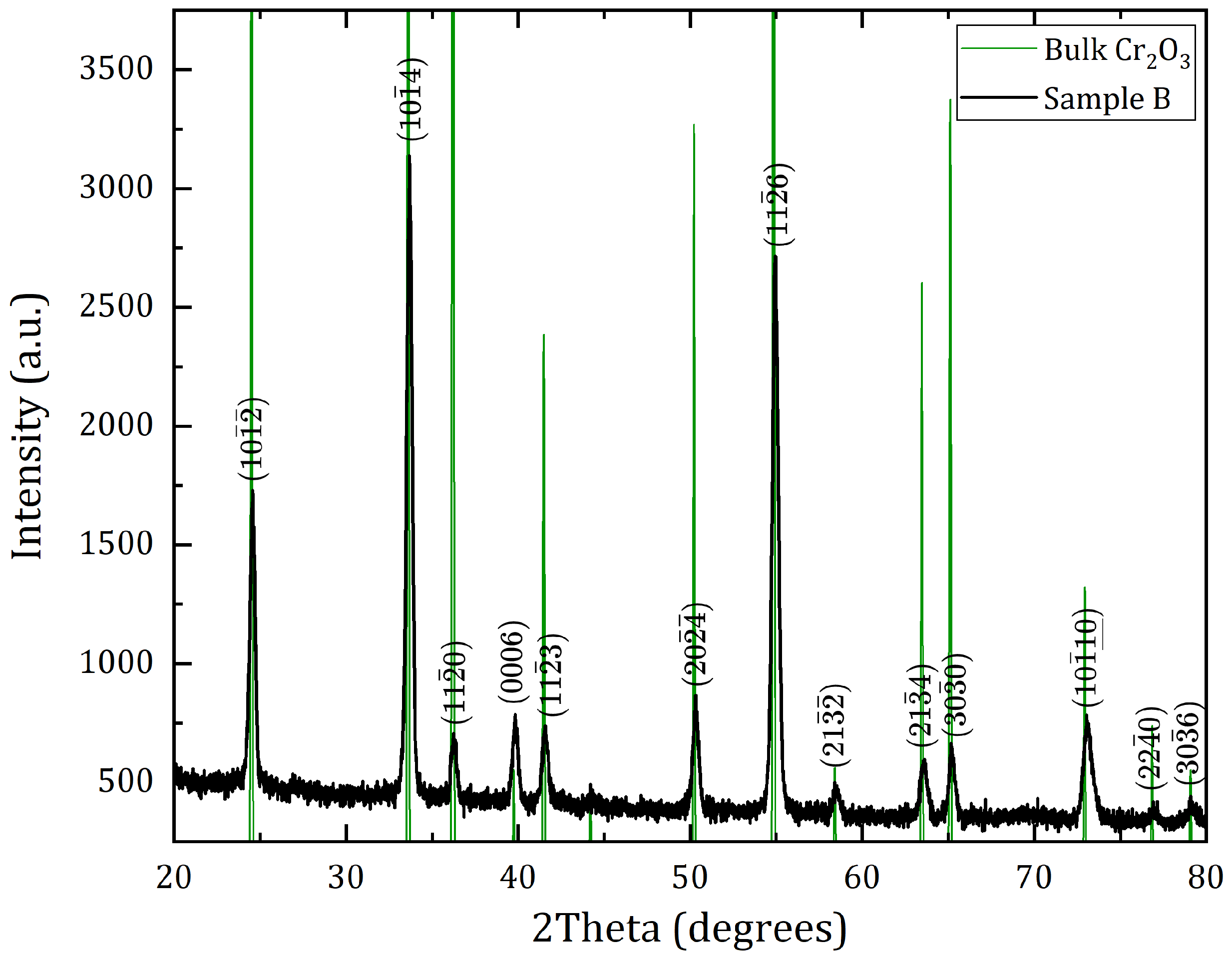
Given the polycrystalline nature of Sample B, the GIXRD technique was applied to determine the composition of the sample and identify possible secondary crystalline phases. The resulting diffractogram is displayed in Figure 3. All detected peaks correspond exclusively to the Cr2O3 compound, as confirmed by energy gap measurements obtained from UV-VIS-NIR absorbance spectra and reported in Figure S5 in the Supplementary Material. This observation aligns well with the Cr-O binary phase diagram [24], where Cr2O3 is the most stable phase under the given deposition conditions. The polycrystalline film exhibits a pronounced texture (preferred grain orientation): the intensity of peaks associated with crystallographic planes parallel to the substrate surface (e.g., the (0006) plane) exceeds that predicted by the theoretical diffractogram, whereas for planes perpendicular to the first ones (e.g., the (1120) plane) they display significantly lower intensity. A θ -2 θ scan of Sample B is shown in Figure S1 in the Supplementary Material for completeness.

4.2. Coating Loss Angle

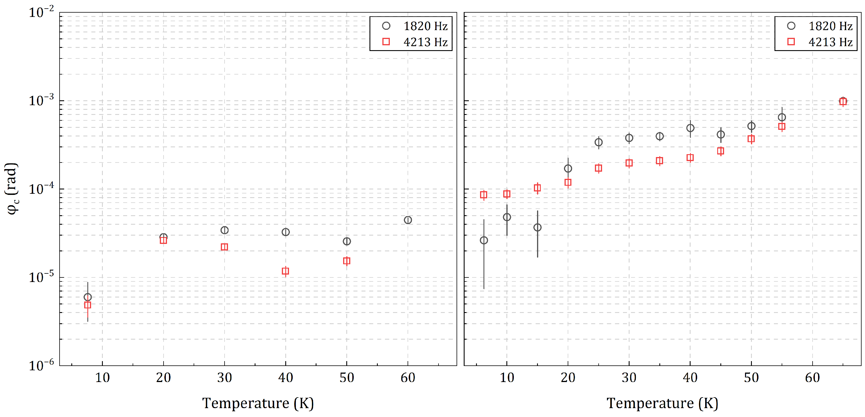
Figure 4 presents the loss angle measured on coating samples A and B. We investigated the first two butterfly modes for sample A and B, at 1820 and 4213 Hz, respectively, from about 6 K to 65 K. Butterfly modes are those with no radial nodal lines and n azimuthal nodal lines, with n > 1 , denoted by (0,n) [43].
The error on the measured coating loss angle φ c was estimated by propagating the uncertainties on the measured dilution factor D and on the loss angles φ 0 and φ of the bare and coated substrates, respectively (see Section 3.2 and Equation (1) for details). The uncertainties associated with φ 0 and φ were determined from a statistical study of the repeatability of loss angle measurements performed on a representative randomly selected sapphire substrate (Siegert 430 μm). Owing to the time-consuming nature of cryogenic GeNS measurements, each measurement was repeated between two and five times, depending on the loss angle, with the largest number of repetitions reserved for the lowest-loss cases. Based on this analysis, and on our broader experience with this class of substrates, the measured loss angles were grouped into four ranges, each associated with a conservative maximum uncertainty, as reported in Table 2. The uncertainty increases as the measured loss angle decreases, most likely because residual coupling between the suspension and the sample, always present to some extent, becomes increasingly significant for very low-loss measurements. The uncertainty on the dilution factor depends only on the uncertainties in the measured resonance frequency and sample mass which don’t show any evident dependency on the temperature.
Sample A exhibits a minimum for both modes at 6 K, with φ c = ( 5 ± 1 ) × 10−6 rad for the (0,3) mode and φ c = ( 6 ± 3 ) × 10−6 rad for the (0,2) mode. The minimum value for Sample B lies at φ c = ( 3 ± 2 ) × 10−5 rad for the (0,2) mode, but it is significantly higher φ c = ( 9 ± 1 ) × 10−5 rad for the (0,3) mode. Excluding the first point, all φ c values of Sample A are approximately an octave apart from one another. On the other hand, Sample B shows an exponential increase in the loss angle as the temperature rises, suggesting the presence of thermally activated defects that can be correlated with the reduced crystalline quality of this sample. The difference in coating thickness between Samples A and B (Table 1) is not expected to contribute significantly to the observed difference in mechanical loss. Although thickness-dependent dissipation cannot be excluded a priori, the fact that the thicker sample exhibits the lower loss angle, demonstrates that such mechanisms, if present, are secondary in comparison with the microstructural defects of the samples discussed in this work. This suggests that the measured dissipation is primarily governed by differences in crystalline quality rather than by the amount of material.
A summary of the main findings and experimental results of this paper is reported in Table 3.

5. Discussion

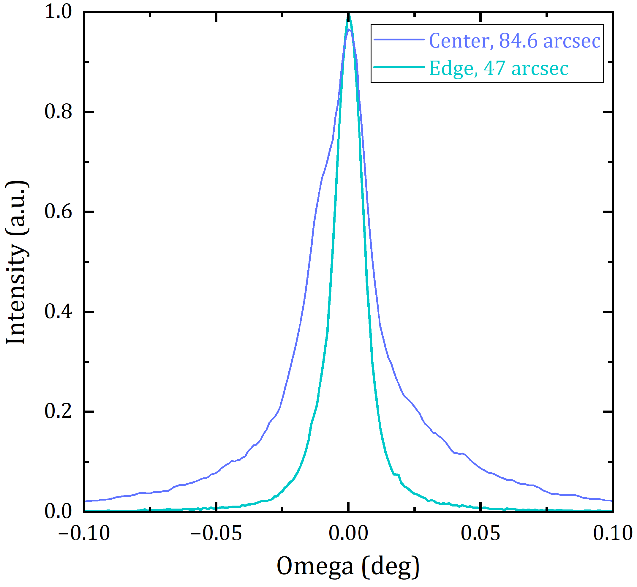
Improving the epitaxial quality of the coating is likely to be one of the most effective ways to reduce its mechanical losses in view of GWD mirror applications. Findings from previous experiments, shown in Figure 5, showed that such improvements can be achieved by increasing the substrate temperature during growth. It was observed that high temperature induces the epitaxy of the corundum-structured Cr2O3 phase and suppresses the formation of randomly oriented crystalline grains. As shown in the figure, a clear transition from amorphous to polycrystalline to epitaxial is observed when increasing the deposition temperature. In addition, Figure 6 suggests that, within the epitaxial growth temperature range, increments in the adatoms thermal energy leads to further reductions in the coating defect density. The figure illustrates the center and edge RC measurements of a test Cr2O3 coating, 550 nm thick, grown at higher substrate temperature, exhibiting a considerably narrower peak width in both regions of the sample, compared to Sample A, and a smaller center-edge gradient in crystal quality. It should be noted that, although the structural characterization clearly establishes that Sample A exhibits substantially higher crystalline quality than Sample B, the present work does not quantify the density of the individual defect types or loss mechanisms. Therefore, the discussion linking twin domains, threading dislocations, and mosaicity to the measured loss angles should be interpreted as a physically motivated hypothesis, supported by the structural characterization and existing literature, rather than as a direct demonstration of the contribution of each defect type.
Importantly, the minimum coating loss angle value of ( 5 ± 1 ) × 10−6 rad, measured for Sample A, is of the same order of magnitude as the values reported for crystalline GaAs/AlGaAs coatings at cryogenic temperatures [21], while remaining substantially lower than those reported for conventional amorphous SiO2/Ti:Ta2O5 coatings operated in the same temperature range [12,13,14]. Although additional optical and technological requirements must still be demonstrated before practical implementation, this result underlines the promise of corundum-structured oxides as a competitive crystalline coating platform for future gravitational-wave detectors.
Although the present comparison suggests that crystalline quality is strongly correlated with the measured mechanical losses, additional factors may also contribute to the dissipation. These include the residual stress state of the film, the quality of the film/substrate interface, oxygen stoichiometry, and the concentration of point defects [44]. While XRD, optical band-gap measurements (Figure S5 in Supplementary Material) and the Cr–O phase diagram consistently support the formation of single-phase Cr2O3, they do not directly determine the oxygen stoichiometry or quantify point-defect concentrations. Consequently, small deviations from ideal stoichiometry, oxygen vacancies or other point defects cannot be excluded and may also influence the measured mechanical losses. Future studies combining structural characterization with direct compositional techniques will be valuable for identifying the microscopic mechanisms governing mechanical dissipation in epitaxial Cr2O3 coatings.
We will now discuss whether the slight differences in the deposition parameters of the two present samples can explain their opposing crystalline quality. As can be seen from Table 1, the substrate temperature and oxygen partial pressure values used to grow Samples A and B were nearly identical. We note here that the deposition rate, used for Sample A and Sample B, differs only slightly: while for Sample B the Cr metal deposition rate was kept constant around 0.1 Å/s, in the case of Sample A the Cr rate was varied from 0.085 Å/s to 0.13 Å/s. However, it is known that the epitaxial growth process of a coating is strongly dependent on the crystallinity of the first few monolayers of the film and it requires a relatively small lattice mismatch with the substrate. Generally, lower deposition rates (below 0.1 Å/s) promote a more ordered and epitaxial growth whereas as the value increases, the growth becomes more disordered and polycrystalline domains appear. This suggests that the large difference in crystallinity between Samples A and B cannot be explained by the difference in deposition rate.
Our results indicate that the substrate pre-annealing step performed at 900 °C for 24 h in ambient conditions, together with the subsequent deposition conditions employed in this work, was not favorable for the growth of a high-quality chromia epitaxial layer. However, since the present study compares only two samples that differ not only in substrate pre-treatment but also slightly in deposition parameters, the poorer crystallinity of Sample B cannot be conclusively attributed to the pre-annealing step alone. Studies in the literature report optimized annealing procedures to produce atomic terraces on sapphire substrates of 1000 °C for 10 h [45]. Cuccureddu et al. stress the influence of orientation miscut on the resulting sapphire surface after annealing, highlighting that larger miscuts (3°) facilitate terrace formation at lower annealing temperatures and that the role of annealing time is marginal for the final microstructure [46]. There was nominally no miscut (±0.2°) on the surface of the substrates used in this study; therefore, ideally an annealing temperature higher than 1100 °C would have been needed to produce well-defined atomic steps. We want to highlight, however, that in this preliminary experiment the annealing temperature and duration were not optimized for sapphire, as the purpose of the heat treatment was to reduce the loss angle φ 0 of the bare substrate and hence increase the accuracy of the coating loss angle estimations. As a matter of fact, several experimental works report high-quality epitaxial growth of Cr2O3 on annealed sapphire substrates, indicating that substrate annealing itself is not detrimental when appropriately optimized [27,47]. Rather, our results suggest that the annealing procedure adopted here was not optimized for promoting high-quality epitaxial growth under the deposition conditions employed. We would also expect that annealed substrates require different deposition parameters to promote epitaxial growth compared to non-annealed ones.
For application in next-generation GWDs, low mechanical losses alone are not sufficient [48]. Candidate mirror coatings must also exhibit low optical absorption, low optical scattering, high chemical stability, and low birefringence. Compared with the amorphous SiO2/Ti:Ta2O5 coatings currently employed in second-generation detectors, Cr2O3 offers a substantially higher refractive index ( n 2.4 , see Figure S4 in the Supplementary Material), making it a promising high-index material for dielectric multilayer mirror coatings. Whether it can also satisfy the stringent optical absorption and scattering requirements of GWD mirrors remains to be established experimentally. The results presented in this work demonstrate that Cr2O3, as a representative corundum-structured oxide, can combine excellent crystalline quality with low cryogenic mechanical losses and smooth surface morphology. Although the low surface roughness measured here is generally favorable for minimizing optical scattering, this relationship must be verified through direct optical measurements. Future works will focus on measuring key optical properties of Cr2O3 coatings, including optical absorption, scattering losses, and birefringence, together with evaluating their compatibility with multilayer mirror architectures.
Beyond Cr2O3 itself, the broader interest lies in the family of corundum-structured oxides (Ga2O3, Fe2O3, V2O3, Ti2O3 to name a few) to which it belongs [49,50]. These materials are promising for this application given the high compatibility with sapphire (proposed substrate for ET-LF, together with silicon), the relatively small lattice mismatch with the other corundum-structured compounds and the almost limitless range of solid solutions possible, which enables the creation of novel materials with ideal physical properties. A promising candidate multilayer for cryogenic interferometers would involve stackings of Ga2O3 and Fe2O3 bilayers, two oxides with large refractive index difference [51,52], small lattice mismatch and ideally displaying similar mechanical losses as the values reported for Cr2O3 in this paper. Concerning applications of this technology for upgraded versions of 2G GWDs operating at room temperature like AdV+, sapphire has been ruled out as operational substrate for the cavity mirrors given its high thermoelastic noise and relatively high optical absorption at room temperature [53,54]. We plan to overcome this issue by detaching the coating from its sacrificial growth sapphire substrate and then bond it to the test mass via a substrate-transfer procedure, similarly to the case of GaAs/AlGaAs multilayers on GaAs [21]. It is important to note that currently no reliable assessment taken at room temperature of loss angle values of any corundum-structured oxide grown on sapphire is available. This stems from the fact that the substrate thermoelastic noise dominates the signal and covers the contribution of the coating, especially for small-size thin samples. In principle, it is not certain that other corundum-structured materials would behave as sapphire in terms of thermo-optic noise, further work needs to be performed to demonstrate the real physical properties of these compounds.

6. Conclusions

In this work, we presented the first structural and mechanical evaluation of epitaxial Cr2O3 coatings for applications in gravitational wave detectors mirrors, including, to the best of our knowledge, the first cryogenic coating loss measurements reported for this material. Two samples, A and B, with significantly different crystalline quality, were fabricated using oxygen-assisted MBE, and their structural and mechanical properties were systematically characterized to investigate the relationship between crystalline quality and cryogenic mechanical loss. Our results demonstrate that the microstructure of the Cr2O3 film appears to have a critical impact on the mechanical losses. Sample A, exhibiting single crystal structure, achieved a minimum coating loss angle of ( 5 ± 1 ) × 10−6 rad at 6 K, one order of magnitude lower than the polycrystalline Sample B, with losses of ( 3 ± 2 ) × 10−5 rad. This value is comparable to the best cryogenic mechanical losses reported for crystalline GaAs/AlGaAs coatings and substantially lower than those of conventional amorphous SiO2/Ti:Ta2O5 coatings, further supporting the potential of corundum-structured oxides for future cryogenic mirror coatings. Structural analysis via XRD and RHEED confirmed that substrate temperature gradients and surface morphology play a decisive role in the growth outcome, with the sample edge (subjected to higher temperature) consistently showing superior crystallinity and lower defect density.
Beyond demonstrating the potential of Cr2O3 itself, this work establishes corundum-structured oxides as a promising new class of crystalline coating materials for cryogenic gravitational wave detectors. The physical and structural compatibility of corundum-structured oxides with sapphire substrates opens a promising route for exploring other X2O3 compounds (e.g., Ga2O3, Fe2O3) or solid solutions ((AxB1−x)2O3) with tailored properties for use in cryogenic mirror coatings. Future work will focus on optimizing epitaxial growth and extending this approach to other corundum-structured oxides.

Supplementary Materials

The following supporting information can be downloaded at: https://www.mdpi.com/article/10.3390/coatings16080895/s1.

Author Contributions

Conceptualization, A.B., J.W.S. and J.-P.L.; methodology, A.B., L.O.M. and M.G.; validation, K.S., W.-F.H., C.B., G.C., J.W.S. and J.-P.L.; formal analysis, A.B., L.O.M., L.S. and B.F.; investigation, A.B., L.O.M., M.G., L.S., K.S., W.-F.H., C.B. and B.F.; resources, G.C., J.W.S. and J.-P.L.; data curation, A.B., L.O.M., M.G. and L.S.; writing—original draft preparation, A.B. and L.O.M.; writing—review and editing, M.G., L.S., K.S., G.C., J.W.S. and J.-P.L.; visualization, A.B., L.O.M. and M.G.; supervision, M.G., G.C. and J.-P.L.; project administration, M.G. and J.-P.L.; funding acquisition, G.C., J.W.S. and J.-P.L. All authors have read and agreed to the published version of the manuscript.

Funding

This research work was funded by Interreg Vlaanderen-Nederland grant number 3E211263, and by Fonds Wetenschappelijk Onderzoek (FWO) grant numbers 3E250047 and 3E221380.

Data Availability Statement

Data will be made available by the corresponding author upon reasonable request.

Acknowledgments

This work has been promoted within the Virgo and Einstein Telescope collaborations. It was a joint effort between KU Leuven and Laboratoire des Matériaux Avancés (LMA). This research was supported by Interreg Vlaanderen-Nederland, project ’R&D Field Lab Etpathfinder’. The authors are grateful for fruitful discussion within the ETpathfinder collaboration. The ETpathfinder project in Maastricht is funded by Interreg Vlaanderen-Nederland, the province of Dutch Limburg, the province of Antwerp, the Flemish Government, the province of North Brabant, the Smart Hub Flemish Brabant, the Dutch Ministry of Economic Affairs, the Dutch Ministry of Education, Culture and Science, and by own funding of the involved partners. In addition the ETpathfinder team acknowledges support from the European Research Council (ERC), the Dutch Research Council (NWO), the Research Foundation Flanders (FWO) and the Dutch National Growth Fund (NGF). This work comes within the scope of the E-TEST project, which is carried out within the framework of the Interreg V-A Euregio Meuse-Rhine Programme, with 7.5 million from the European Regional Development Fund (ERDF). By investing EU funds in Interreg projects, the European Union is investing directly in economic development, innovation, territorial development, social inclusion, and education in the Euregio Meuse-Rhine region. For a thorough review, the authors would like to thank European Union for this support and investment. J.W.S. acknowledges the FWO Infrastructure projects AKUL/13/19 and I000920N. The authors thank Joris Van de Vondel for use of the AFM instrument and Alex Amato for the fruitful discussion on the optical modeling of the transmission curves.

Conflicts of Interest

The authors declare no conflicts of interest. The funders had no role in the design of the study; in the collection, analyses, or interpretation of data; in the writing of the manuscript; or in the decision to publish the results.

References

  1. Maggiore, M.; Broeck, C.V.D.; Bartolo, N.; Belgacem, E.; Bertacca, D.; Bizouard, M.A.; Branchesi, M.; Clesse, S.; Foffa, S.; Garciá-Bellido, J.; et al. Science case for the Einstein telescope. J. Cosmol. Astropart. Phys. 2020, 2020, 50. [Google Scholar] [CrossRef]
  2. Accadia, T.; Acernese, F.; Alshourbagy, M.; Amico, P.; Antonucci, F.; Aoudia, S.; Arnaud, N.; Arnault, C.; Arun, K.G.; Astone, P.; et al. Virgo: A laser interferometer to detect gravitational waves. J. Instrum. 2012, 7, P03012. [Google Scholar] [CrossRef]
  3. Acernese, F.; Agathos, M.; Agatsuma, K.; Aisa, D.; Allemandou, N.; Allocca, A.; Amarni, J.; Astone, P.; Balestri, G.; Ballardin, G.; et al. Advanced Virgo: A second-generation interferometric gravitational wave detector. Class. Quantum Gravity 2014, 32, 024001. [Google Scholar] [CrossRef]
  4. Collaboration, T.L.S.; Aasi, J.; Abbott, B.P.; Abbott, R.; Abbott, T.; Abernathy, M.R.; Ackley, K.; Adams, C.; Adams, T.; Addesso, P.; et al. Advanced LIGO. Class. Quantum Gravity 2015, 32, 074001. [Google Scholar] [CrossRef]
  5. Abbott, B.P.; Abbott, R.; Abbott, T.D.; Abernathy, M.R.; Acernese, F.; Ackley, K.; Adams, C.; Adams, T.; Addesso, P.; Adhikari, R.X.; et al. GW150914: The Advanced LIGO Detectors in the Era of First Discoveries. Phys. Rev. Lett. 2016, 116, 131103. [Google Scholar] [CrossRef] [PubMed]
  6. Acernese, F.; Agathos, M.; Ain, A.; Albanesi, S.; Alléné, C.; Allocca, A.; Amato, A.; Andia, M.; Andrade, T.; Andres, N.; et al. Advanced Virgo Plus: Future Perspectives. J. Phys. Conf. Ser. 2023, 2429, 012040. [Google Scholar] [CrossRef]
  7. Abernathy, M.; Acernese, F.; Ajith, P.; Allen, B.; Amaro-Seoane, P.; Andersson, N.; Aoudia, S.; Astone, P.; Krishnan, B.; Barack, L.; et al. ET Design Study; European Commission Report: Brussels, Belgium, 2011; ET-0106A-10. [Google Scholar]
  8. Einstein Telescope Collaboration. Einstein Telescope Design Report; ET-0007C-20; Einstein Telescope Collaboration: Maastricht, The Netherlands, 2020; Available online: https://apps.et-gw.eu/tds/ql/?c=15418 (accessed on 25 April 2026).
  9. Utina, A.; Amato, A.; Arends, J.; Arina, C.; de Baar, M.; Baars, M.; Baer, P.; van Bakel, N.; Beaumont, W.; Bertolini, A.; et al. ETpathfinder: A cryogenic testbed for interferometric gravitational-wave detectors. Class. Quantum Gravity 2022, 39, 215008. [Google Scholar] [CrossRef]
  10. Steinlechner, J. Development of mirror coatings for gravitational-wave detectors. Philos. Trans. R. Soc. A Math. Phys. Eng. Sci. 2018, 376, 20170282. [Google Scholar] [CrossRef] [PubMed]
  11. Granata, M.; Amato, A.; Balzarini, L.; Canepa, M.; Degallaix, J.; Forest, D.; Dolique, V.; Mereni, L.; Michel, C.; Pinard, L.; et al. Amorphous optical coatings of present gravitational-wave interferometers. Class. Quantum Gravity 2020, 37, 095004. [Google Scholar] [CrossRef]
  12. Martin, I.W.; Nawrodt, R.; Craig, K.; Schwarz, C.; Bassiri, R.; Harry, G.; Hough, J.; Penn, S.; Reid, S.; Robie, R.; et al. Low temperature mechanical dissipation of an ion-beam sputtered silica film. Class. Quantum Gravity 2014, 31, 035019. [Google Scholar] [CrossRef]
  13. Granata, M.; Craig, K.; Cagnoli, G.; Carcy, C.; Cunningham, W.; Degallaix, J.; Flaminio, R.; Forest, D.; Hart, M.; Hennig, J.S.; et al. Cryogenic measurements of mechanical loss of high-reflectivity coating and estimation of thermal noise. Opt. Lett. 2013, 38, 5268–5271. [Google Scholar] [CrossRef] [PubMed]
  14. Martin, I.; Armandula, H.; Comtet, C.; Fejer, M.M.; Gretarsson, A.; Harry, G.; Hough, J.; Mackowski, J.M.M.; MacLaren, I.; Michel, C.; et al. Measurements of a low-temperature mechanical dissipation peak in a single layer of Ta2O5 doped with TiO2. Class. Quantum Gravity 2008, 25, 055005. [Google Scholar] [CrossRef]
  15. Cesarini, E.; Lorenzini, M.; Amato, A.; Cagnoli, G.; Cassar, Q.; Dickmann, J.; Granata, M.; Fafone, V.; Heinert, D.; Kroker, S.; et al. The Virgo Coating Collaboration: A detailed study on thermoelasticity in crystalline materials and other research lines. Proc. Sci. 2018, 325. [Google Scholar] [CrossRef]
  16. Topp, K.; Cahill, D. Elastic properties of several amorphous solids and disordered crystals below 100 K. Z. Phys. B 1996, 101, 235–245. [Google Scholar] [CrossRef]
  17. Cole, G.D. Cavity optomechanics with low-noise crystalline mirrors. In Optical Trapping and Optical Micromanipulation IX; SPIE: Washington, DC, USA, 2012; Volume 8458, p. 845807. [Google Scholar] [CrossRef]
  18. Jewell, J.; McCall, S.; Gossard, A.; English, J. GaAs-AlAs monolithic microresonator arrays. Appl. Phys. Lett. 1987, 51, 94–96. [Google Scholar] [CrossRef]
  19. Steinlechner, J.; W Martin, I.; Bell, A.; Cole, G.; Hough, J.; Penn, S.; Rowan, S.; Steinlechner, S. Mapping the optical absorption of a substrate-transferred crystalline AlGaAs coating at 1.5 μm. Class. Quantum Gravity 2015, 32, 105008. [Google Scholar] [CrossRef]
  20. Cole, G.D.; Zhang, W.; Bjork, B.J.; Follman, D.; Heu, P.; Deutsch, C.; Sonderhouse, L.; Robinson, J.; Franz, C.; Alexandrovski, A.; et al. High-performance near- and mid-infrared crystalline coatings. Optica 2016, 3, 647. [Google Scholar] [CrossRef]
  21. Cole, G.D.; Zhang, W.; Martin, M.J.; Ye, J.; Aspelmeyer, M. Tenfold reduction of Brownian noise in high-reflectivity optical coatings. Nat. Photonics 2013, 7, 644–650. [Google Scholar] [CrossRef]
  22. Dobrovinskaya, E.R.; Lytvynov, L.A.; Pishchik, V. Properties of sapphire. In Sapphire: Material, Manufacturing, Applications; Springer: Boston, MA, USA, 2009; pp. 55–176. [Google Scholar]
  23. Povoden, E.; Nicholas Grundy, A.; Gauckler, L.J. Thermodynamic reassessment of the Cr-O system in the framework of solid oxide fuel cell (SOFC) research. J. Phase Equilibria Diffus. 2006, 27, 353–362. [Google Scholar] [CrossRef]
  24. Mittal, A.; Albertsson, G.J.; Gupta, G.S.; Seetharaman, S.; Subramanian, S. Some thermodynamic aspects of the oxides of chromium. Metall. Mater. Trans. B Process Metall. Mater. Process. Sci. 2014, 45, 338–344. [Google Scholar] [CrossRef]
  25. Al-Kuhaili, M.F.; Durrani, S.M. Optical properties of chromium oxide thin films deposited by electron-beam evaporation. Opt. Mater. 2007, 29, 709–713. [Google Scholar] [CrossRef]
  26. Makushko, P.; Kosub, T.; Pylypovskyi, O.V.; Hedrich, N.; Li, J.; Pashkin, A.; Avdoshenko, S.; Hübner, R.; Ganss, F.; Wolf, D.; et al. Flexomagnetism and vertically graded Néel temperature of antiferromagnetic Cr2O3 thin films. Nat. Commun. 2022, 13, 6745. [Google Scholar] [CrossRef] [PubMed]
  27. Iwata, N.; Kuroda, T.; Yamamoto, H. Mechanism of growth of Cr2O3 thin films on (1102), (1120), and (0001) surfaces of sapphire substrates by direct current-radio frequency magnetron sputtering. Jpn. J. Appl. Phys. 2012, 51, 11PG12. [Google Scholar] [CrossRef]
  28. Pinho, P.V.B.; Chartier, A.; Miserque, F.; Menut, D.; Moussy, J.B. Impact of epitaxial strain on crystal field splitting of α-Cr2O3 (0001) thin films quantified by X-ray photoemission spectroscopy. Mater. Res. Lett. 2021, 9, 163–168. [Google Scholar] [CrossRef]
  29. Ekawa, H.; Sameshima, H.; Toyoki, K.; Nakatani, R.; Shiratsuchi, Y. Formation of pseudo-morphic domain in Cr2O3 (0001) epitaxial film grown on α-Al2O3 (0001) and its effect on Néel temperature. Jpn. J. Appl. Phys. 2024, 63, 09SP33. [Google Scholar] [CrossRef]
  30. Fujita, S.; Kaneko, K. Epitaxial growth of corundum-structured wide band gap III-oxide semiconductor thin films. J. Cryst. Growth 2014, 401, 588–592. [Google Scholar] [CrossRef]
  31. Hinuma, Y.; Gake, T.; Oba, F. Band alignment at surfaces and heterointerfaces of Al2O3, Ga2O3, In2O3, and related group-III oxide polymorphs: A first-principles study. Phys. Rev. Mater. 2019, 3, 084605. [Google Scholar] [CrossRef]
  32. Sawada, H. Residual electron density study of chromium sesquioxide by crystal structure and scattering factor refinement. Mater. Res. Bull. 1994, 29, 239–245. [Google Scholar] [CrossRef]
  33. Klapetek, P.; Necas, D.; Anderson, C. Gwyddion user guide. Czech Metrol. Inst. 2004, 2007, 2009. [Google Scholar]
  34. Li, T.; Aguilar Sandoval, F.A.; Geitner, M.; Bellon, L.; Cagnoli, G.; Degallaix, J.; Dolique, V.; Flaminio, R.; Forest, D.; Granata, M.; et al. Measurements of mechanical thermal noise and energy dissipation in optical dielectric coatings. Phys. Rev. D 2014, 89, 092004. [Google Scholar] [CrossRef]
  35. Cesarini, E.; Lorenzini, M.; Campagna, E.; Martelli, F.; Piergiovanni, F.; Vetrano, F.; Losurdo, G.; Cagnoli, G. A “gentle” nodal suspension for measurements of the acoustic attenuation in materials. Rev. Sci. Instrum. 2009, 80, 053904. [Google Scholar] [CrossRef] [PubMed]
  36. Granata, M.; Balzarini, L.; Degallaix, J.; Dolique, V.; Flaminio, R.; Forest, D.; Hofman, D.; Michel, C.; Pedurand, R.; Pinard, L.; et al. Internal Friction and Young’s Modulus Measurements on SiO2 and Ta2O5 Films Done with an Ultra-High Q Silicon-Wafer Suspension. Arch. Metall. Mater. 2015, 1, 365. [Google Scholar] [CrossRef]
  37. Granata, M.; Amato, A.; Bischi, M.; Bazzan, M.; Cagnoli, G.; Canepa, M.; Chicoine, M.; Di Michele, A.; Favaro, G.; Forest, D.; et al. Optical and Mechanical Properties of Ion-Beam-Sputtered MgF2 Thin Films for Gravitational-Wave Interferometers. Phys. Rev. Appl. 2022, 17, 034058. [Google Scholar] [CrossRef]
  38. Tarre, A.; Carlotti, G.; Gerst, A.; Mändar, H.; Niilisk, A.; Sammelselg, V.; Socino, G.; Rosental, A. C-plane chromia on c-plane sapphire. Phys. Status Solidi C 2009, 6, 1472–1475. [Google Scholar] [CrossRef]
  39. Mändar, H.; Uustare, T.; Aarik, J.; Tarre, A.; Rosental, A. Characterization of asymmetric rhombohedral twin in epitaxial α-Cr2O3 thin films by X-ray and electron diffraction. Thin Solid Film. 2007, 515, 4570–4579. [Google Scholar] [CrossRef]
  40. Multiphysics, C. Introduction to Comsol Multiphysics®; COMSOL Multiphysics: Burlington, MA, USA, 1998; Volume 9, p. 32. [Google Scholar]
  41. Jeong, S.Y.; Lee, J.B.; Na, H.; Seong, T.Y. Epitaxial growth of Cr2O3 thin film on Al2O3 (0001) substrate by radio frequency magnetron sputtering combined with rapid-thermal annealing. Thin Solid Film. 2010, 518, 4813–4816. [Google Scholar] [CrossRef]
  42. Kosub, T.; Kopte, M.; Hühne, R.; Appel, P.; Shields, B.; Maletinsky, P.; Hübner, R.; Liedke, M.O.; Fassbender, J.; Schmidt, O.G.; et al. Purely antiferromagnetic magnetoelectric random access memory. Nat. Commun. 2017, 8, 13985. [Google Scholar] [CrossRef] [PubMed]
  43. Cagnoli, G.; Lorenzini, M.; Cesarini, E.; Piergiovanni, F.; Granata, M.; Heinert, D.; Martelli, F.; Nawrodt, R.; Amato, A.; Cassar, Q.; et al. Mode-dependent mechanical losses in disc resonators. Phys. Lett. A 2018, 382, 2165–2173. [Google Scholar] [CrossRef]
  44. Vila, M.; Rubio-Zuazo, J.; Lucas, I.; Magen, C.; Prados, A.; Salas-Colera, E.; Arnay, I.; Castro, G.R. Ferromagnetic epitaxial Cr2O3 thin films grown on oxide substrates by pulsed laser deposition. Appl. Surf. Sci. 2020, 534, 147638. [Google Scholar] [CrossRef]
  45. Maeda, T.; Yoshimoto, M.; Ohnishi, T.; Lee, G.; Koinuma, H. Orientation-defined molecular layer epitaxy of α-Al2O3 thin films. J. Cryst. Growth 1997, 177, 95–101. [Google Scholar] [CrossRef]
  46. Cuccureddu, F.; Murphy, S.; Shvets, I.; Porcu, M.; Zandbergen, H.; Sidorov, N.; Bozhko, S. Surface morphology of c-plane sapphire (α-alumina) produced by high temperature anneal. Surf. Sci. 2010, 604, 1294–1299. [Google Scholar] [CrossRef]
  47. Mashiko, H.; Oshima, T.; Ohtomo, A. Epitaxial Structures of Band-Gap-Engineered α-(CrxFe1-x)2O3 (0 ≤ x ≤ 1) Films Grown on C-Plane Sapphire. Jpn. J. Appl. Phys. 2012, 51, 11S. [Google Scholar] [CrossRef]
  48. Reid, S.; Martin, I.W. Development of mirror coatings for gravitational wave detectors. Coatings 2016, 6, 61. [Google Scholar] [CrossRef]
  49. Spencer, J.A.; Mock, A.L.; Jacobs, A.G.; Schubert, M.; Zhang, Y.; Tadjer, M.J. A review of band structure and material properties of transparent conducting and semiconducting oxides: Ga2O3, Al2O3, In2O3, ZnO, SnO2, CdO, NiO, CuO, and Sc2O3. Appl. Phys. Rev. 2022, 9, 011315. [Google Scholar] [CrossRef]
  50. Prewitt, C.T.; Shannon, R.D.; Rogers, D.B.; Sleight, A.W. The C Rare Earth Oxide-Corundum Transition and Crystal Chemistry of Oxides Having the Corundum Structure. Inorg. Chem. 1968, 8, 1985–1993. [Google Scholar]
  51. Carrasco, D.; Nieto-Pinero, E.; Alonso-Orts, M.; Serna, R.; San Juan, J.M.; Nó, M.L.; Jesenovec, J.; McCloy, J.S.; Nogales, E.; Méndez, B. Temperature-dependent anisotropic refractive index in β-Ga2O3: Application in interferometric thermometers. Nanomaterials 2023, 13, 1126. [Google Scholar] [CrossRef] [PubMed]
  52. Al-Kuhaili, M.; Saleem, M.; Durrani, S. Optical properties of iron oxide (α-Fe2O3) thin films deposited by the reactive evaporation of iron. J. Alloys Compd. 2012, 521, 178–182. [Google Scholar] [CrossRef]
  53. Hirose, E.; Bajuk, D.; Billingsley, G.; Kajita, T.; Kestner, B.; Mio, N.; Ohashi, M.; Reichman, B.; Yamamoto, H.; Zhang, L. Sapphire mirror for the KAGRA gravitational wave detector. Phys. Rev. D Part. Fields Gravit. Cosmol. 2014, 89, 062003. [Google Scholar] [CrossRef]
  54. Black, E.D.; Villar, A.; Libbrecht, K.G. Thermoelastic-damping noise from sapphire mirrors in a fundamental-noise-limited interferometer. Phys. Rev. Lett. 2004, 93, 241101. [Google Scholar] [CrossRef] [PubMed]
Figure 1. (a) RHEED pattern around the [1120] direction and (b) AFM image 1.5 × 1.5 μm2 of sample A; (c) RHEED pattern around the [1120] direction and (d) AFM image 1 × 1 μm2 of sample B.
Coatings 16 00895 g001
Figure 2. XRD characterization of Sample A. Black curves correspond to measurements collected at the center of the 2″ wafer, while red curves correspond to the edge region, located 19 mm from the center. (a) Symmetric θ -2 θ scan around the Cr2O3 and Al2O3 (0006) reflections. The shift of the Cr2O3 peak relative to the dotted cyan line, representing the relaxed bulk lattice position, indicates residual strain in the film, while the asymmetric peak tail indicates a pronounced strain gradient along the film thickness. The inset reports rocking curves around the Cr2O3 (0006) reflection. The edge region exhibits a substantially narrower FWHM (57 arcsec) than the center (278 arcsec), indicating superior epitaxial quality. (b) ϕ scan around the Cr2O3 (1010) reflection. The three main peaks, separated by 120°, confirm epitaxial alignment between the film and the sapphire substrate, while the weaker peaks shifted by 60° arise from twin domains. (c) Reciprocal space map (RSM) around the Cr2O3 and Al2O3 (1010) reflections in the sample edge region. The Cr2O3 peak position indicates that the edge region is approximately 95% relaxed. Its elongated shape along the Qx direction suggests the presence of threading dislocations that accommodate lattice mismatch during epitaxial growth.
Coatings 16 00895 g002
Figure 3. GIXRD pattern of Sample B (black) compared with the reference diffraction peak positions of bulk Cr2O3 (green). All observed reflections can be indexed to the corundum Cr2O3 phase, indicating the absence of detectable secondary crystalline phases within the sensitivity of the measurement.
Coatings 16 00895 g003
Figure 4. Coating loss angle of samples A (left) and B (right), as a function of temperature and frequency. See Section 3.2 and Equation (1) for more details.
Coatings 16 00895 g004
Figure 5. RHEED pattern of four different Cr2O3 films on sapphire grown, without any pre-treatment or pre-annealing step, at different deposition temperatures. The actual temperature of the sapphire wafers was somewhat lower than the value indicated here, which corresponds to the sample holder. Consequently, the crucial parameter to consider is not the absolute temperature, but rather the temperature difference between the samples.
Coatings 16 00895 g005
Figure 6. Rocking Curve XRD scan of a 550 nm thick epitaxial Cr2O3 film, showing high crystalline quality, both at the center and at the edge, that is superior to Sample A.
Coatings 16 00895 g006
Table 1. Sample properties and deposition parameters. The thickness values were extracted by fitting the transmittivity spectra (see Figure S3 in Supplementary Material).
SamplePre-AnnealingDeposition Temperature (°C)Oxygen Partial Pressure (Torr)Deposition Time (min)Thickness (nm)
ANo8551.8 × 10−6387529
BYes8851.8 × 10−6330341
Table 2. Experimental uncertainties associated to measured loss angle values φ 0 and φ . See Section 3.2 and Equation (1) for more details.
Value Range (×10−8 Rad)Uncertainty
0.42–1.0333%
1.03–3.0811%
3.08–4.227%
>4.225%
Table 3. Overview of the main average physical properties measured for Sample A and B. The reported mechanical losses only represent the minimum value found, it does not specify the butterfly mode associated.
SampleGrowth ModeAFM Roughness (nm)Mechanical Losses at 6 K (Rad)Mechanical Losses at 40 K (Rad)
AEpitaxial1.0 ( 5 ± 1 ) × 10−6 ( 12 ± 2 ) × 10−6
BPolycrystalline6.5 ( 3 ± 2 ) × 10−5 ( 23 ± 3 ) × 10−5
Disclaimer/Publisher’s Note: The statements, opinions and data contained in all publications are solely those of the individual author(s) and contributor(s) and not of MDPI and/or the editor(s). MDPI and/or the editor(s) disclaim responsibility for any injury to people or property resulting from any ideas, methods, instructions or products referred to in the content.