Article

Cage Stability of an Oil-Lubricated High-Speed Angular Contact Ball Bearing in a Multi-Wire Saw

1
College of Mechanical and Electronic Engineering, Nanjing Forestry University, Nanjing 210037, China
2
Department of Artificial Intelligence, Shanxi Polytechnic College, Taiyuan 030000, China
*
Author to whom correspondence should be addressed.
Coatings 2026, 16(5), 598; https://doi.org/10.3390/coatings16050598
Submission received: 30 March 2026 / Revised: 6 May 2026 / Accepted: 13 May 2026 / Published: 14 May 2026

Highlights

What are the main findings?
  • A dynamic model of angular contact ball bearings considering the oil-phase volume distribution on the cage surface was established.
  • Guiding clearance, pocket clearance, and bearing rotational speed affect the oil-phase volume fraction on the cage surface.
  • Increasing guiding clearance, pocket clearance, and rotational speed leads to a higher cage slip ratio.
What are the implications of the main findings?
  • The regression model can predict the oil-phase volume fraction on the cage surface.
  • Moderately increasing the guiding clearance and axial load improves cage stability.
  • Large pocket clearance and high radial load reduce cage stability.

Abstract

A 7224C high-speed angular contact ball bearing used in a multi-wire sawing machine is selected as the research object to investigate the cage dynamic characteristics under oil-lubricated operating conditions. First, in order to determine the oil-phase volume fraction on the cage surface, a fluid-domain model of the bearing cavity is established, and numerical simulations are performed using the VOF multiphase-flow method coupled with the RNG k-ε turbulence model. The effects of the guiding clearance, pocket clearance, and rotational speed are analyzed, and a regression equation for the cage-surface oil-phase volume fraction is developed based on a uniform test design. Subsequently, a bearing dynamic model is constructed, in which lubrication-related parameters are determined based on the regression equation, and the force balance and equations of motion for each component are derived. Finally, using the slip ratio and the deviation ratio of the cage-centroid whirl velocity as evaluation indices, the influences of multiple parameters on cage stability are examined. The results indicate that increasing the clearances and rotational speed leads to a higher slip ratio, whereas increasing the axial and radial loads reduces the slip ratio. Moreover, enlarging the guiding clearance and increasing the axial load improve cage stability, while a larger pocket clearance and an excessively high radial load deteriorate cage stability.

1. Introduction

Multi-wire sawing machines are key equipment for the precision processing of hard and brittle materials such as semiconductor and photovoltaic wafers. The high-speed angular contact ball bearings supporting the main roller are critical components that largely determine machining accuracy, operating efficiency, and service life. Under high-speed oil-lubricated conditions, the bearing cage serves as the core element for the positioning and guidance of the rolling elements; its lubrication state and dynamic stability directly govern key bearing performances, including slip, vibration, and temperature rise. If insufficient lubrication, cage whirl, or instability occurs, bearing performance and lifetime may be severely degraded, thereby compromising the stable and reliable operation of the entire system. The dynamic behavior of the cage is therefore a decisive factor in ensuring the performance of high-speed ball bearings. Once unstable cage motion develops, it can induce torque fluctuations and squeal noise, accelerate cage wear, and, in severe cases, lead to cage fracture, resulting in bearing precision loss or seizure and ultimately catastrophic failure [1]. Accordingly, investigating the lubrication and dynamic characteristics of cages in high-speed angular contact ball bearings for multi-wire sawing machines is of significant engineering value for improving the reliability of critical components in such equipment.
High-speed angular contact ball bearings typically operate under high rotational speeds, variable loads, and oil–air two-phase lubrication, where cage motion is governed by the coupled effects of the lubrication flow field, internal mechanical clearances, load, and speed. As a result, the lubrication mechanisms and dynamic response of the cage are highly complex. To date, extensive studies have been conducted worldwide on bearing-cage behavior. Kingsbury [2] was among the first to experimentally reveal the correlation between cage unstable motion and fluctuations in bearing torque, indicating that the friction force between the balls and the cage pockets is the primary driver of cage whirl; such unstable whirling can in turn induce variations in friction torque and squeal noise. Jiang [3] developed a ball-bearing dynamic model with 4 degrees of freedom (DOF) for the ball and 6 DOF for the cage to investigate cage dynamics in rolling bearings. Zhang [4] proposed a 10-DOF nonlinear dynamic model to analyze the influence of cage wear on the system dynamics under thermal expansion, while accounting for interaction forces between the cage and other bearing components. Wang [5] established a spatial dynamic model to study cage stability and rolling-element slip under a prescribed misalignment angle. Qiu [6] developed a rolling-bearing dynamic model that considers grease lubrication and cage deformation at low temperature, investigated cage deformation under the combined effects of centrifugal force and low-temperature conditions, and analyzed its influence on pocket clearance and guiding clearance. Gupta [7,8] constructed a comprehensive bearing dynamic model in which all components possess 6 DOF; the model can reproduce transient motions of bearing components under time-varying operating conditions and systematically elucidates the effects of operating conditions, lubrication, friction, and geometric parameters on cage stability. In recent years, cage dynamic studies in China based on rolling-bearing dynamic models have progressed rapidly. Using the Gupta framework, Liu et al. [9,10,11,12,13,14] introduced reasonable simplifications tailored to specific operating conditions, providing important references for cage dynamic performance analysis. These studies collectively indicate that cage pocket clearance and guiding clearance are key geometric parameters governing cage dynamic performance.
Previous studies have mainly focused on two aspects: cage dynamic modeling and oil–air two-phase flow in bearing cavities. The former emphasizes the effects of clearance, load, and rotational speed on cage whirl, collision, and slip, whereas the latter mainly concerns lubricant transport, flow distribution, and temperature rise. Although these studies provide a basis for understanding lubrication behavior and cage motion in high-speed bearings, a clear parameter-transfer relationship between the lubrication flow field and cage dynamic response is still lacking. In particular, the local oil-phase volume fraction on the cage surface has rarely been quantified and introduced into the dynamic model. Therefore, the influence of local lubrication-state variations on cage slip and whirl stability remains to be further clarified. To fill this gap, this study investigates the lubrication behavior and dynamic stability of the cage in a 7224C high-speed angular contact ball bearing used in the main roller of a multi-wire sawing machine under oil-lubricated conditions. A bearing-cavity flow-field model is first established using the VOF multiphase model coupled with the RNG k-ε turbulence model to evaluate the effects of guiding clearance, pocket clearance, and rotational speed on the average oil-phase volume fraction on cage surfaces. On this basis, a regression model for predicting the lubrication state is developed using a uniform design method. The lubrication-related parameters obtained from the flow-field analysis are then incorporated into a bearing dynamic model, enabling an integrated analysis of the effects of cage-surface lubrication conditions on cage slip and whirl stability. Finally, by employing the slip ratio and the deviation ratio of cage-centroid whirl velocity as evaluation indices, the influences of structural parameters and operating conditions on cage stability are systematically clarified, providing a theoretical basis for cage-parameter optimization and operating-condition matching in high-speed angular contact ball bearings. Compared with previous studies, this work does not analyze the bearing-cavity flow field or cage dynamics separately. Instead, the local lubrication state on the cage surface is first quantified using CFD, and regression relationships among the oil-phase volume fraction, structural parameters, and rotational speed are established. The equivalent properties of the oil–air mixture predicted by the regression model are then introduced into the cage dynamic model, allowing lubrication-state variations to affect cage slip and whirl response through the fluid drag torque acting on the cage. Thus, a parameter-transfer relationship between bearing-cavity flow-field analysis and cage-stability analysis is established.

2. Materials and Methods

This study focuses on a 7224C high-speed angular contact ball bearing used in the main roller of a multi-wire sawing machine. A three-dimensional fluid-domain model of the bearing cavity was established, and the oil volume fraction on the cage surface was analyzed using the VOF multiphase-flow model, the RNG k–ε turbulence model, and the MRF method. On this basis, a predictive model was developed through uniform experimental design and quadratic regression analysis. Furthermore, a bearing dynamic model incorporating the influence of the lubrication flow field was established, providing a methodological foundation for the analysis of cage slip ratio and stability.

2.1. Flow-Field Analysis in the Bearing Cavity of an Oil-Lubricated High-Speed Angular Contact Ball Bearing for a Multi-Wire Sawing Machine

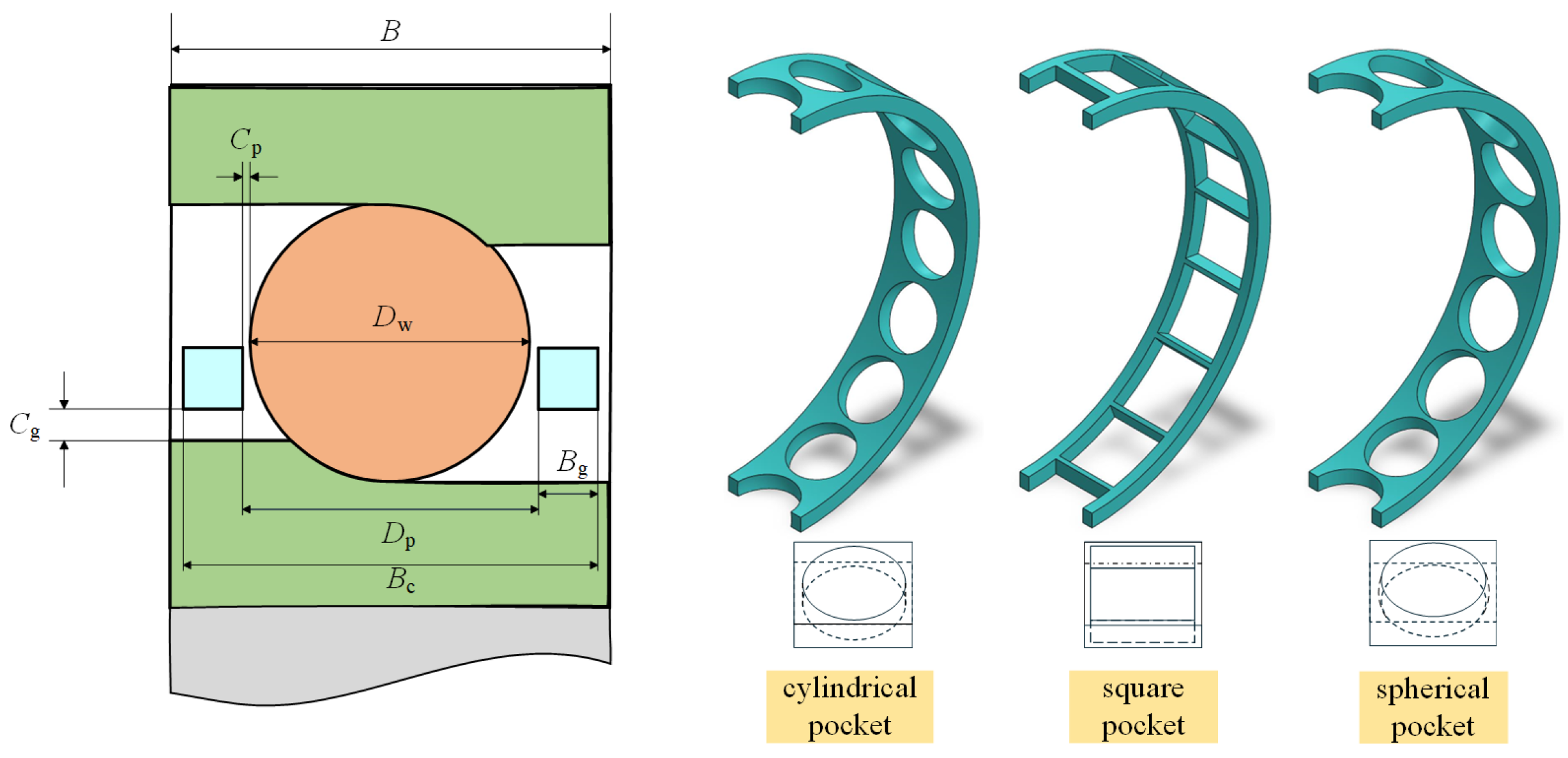
In bearing lubrication simulations, the quality of geometric modeling and mesh generation has a significant impact on the convergence and accuracy of the numerical results. The present work focuses on the flow field inside the bearing cavity; therefore, the simulation model should be constructed as the internal fluid domain of the bearing cavity. Prior to defining the specific geometry of the cavity fluid domain, a geometric model of the bearing assembly must first be established. The detailed structure of the angular contact ball bearing investigated in this study is shown in Figure 1:

2.1.1. Establishment of the Fluid-Domain Model for the Cavity of an Angular Contact Ball Bearing

A 7224C angular contact ball bearing (SKF) used for the main roller of a multi-wire sawing machine is selected as the research object. Based on its geometric parameters, a three-dimensional model including the inner and outer rings, rolling elements, and cage is established. The cage geometric parameters are given in Table 1, and a schematic of the inner-ring-guided cage configuration is shown in Figure 1. Using the DesignModeler and SpaceClaim modules in ANSYS Workbench (2025R1), the internal fluid domain is extracted and partitioned. The overall flow domain, including the annular jet flow at the nozzle outlet, is divided into three subdomains: the stationary fluid domains at the two end faces of the bearing and the rotating fluid domain in the middle. The interfaces between adjacent subdomains are coupled using interface connections. To improve computational convergence while maintaining sufficient accuracy, the effects of load-induced bearing displacement and local deformation on the flow field are neglected, and the following simplifications are introduced: (1) the bearing rotational speed is assumed to be constant, and speed fluctuations are not considered [15,16]; (2) the rolling-element size is slightly reduced to increase the clearance between the rolling elements and the raceways, thereby avoiding mesh distortion and reducing computational cost [17].
These simplifications may affect local flow-field details, but their influence on the relative trends investigated in this study is limited. Neglecting load-induced displacement and elastic deformation may underestimate the effect of local clearance non-uniformity on oil-phase distribution. The constant-speed assumption does not consider transient flow fluctuations during start-up, shutdown, acceleration, or deceleration. Slightly reducing the ball size helps avoid mesh distortion and improve numerical stability, but may slightly weaken the local shear and squeezing effects near the ball–raceway contacts. Therefore, the CFD results are mainly used to analyze the relative variation in oil-phase volume fraction under different clearance and speed conditions.
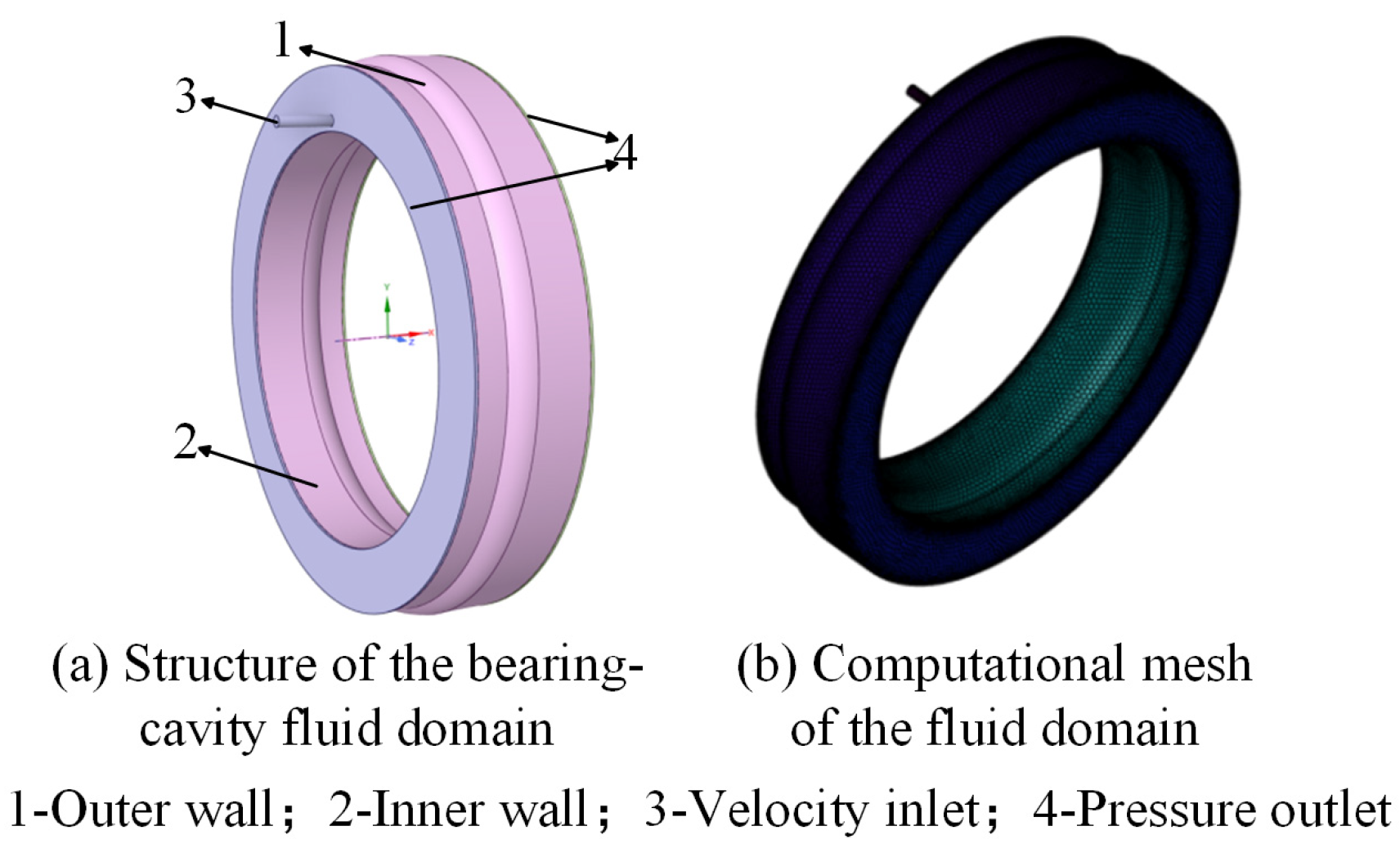
Based on the above geometric model of the angular contact ball bearing, a fluid-domain model of the bearing cavity is established. For the jet-oil lubrication and high-speed operating conditions, a lubricant inlet and outlets at the two end faces of the bearing are specified, as shown in the complete bearing-cavity fluid-domain model in Figure 2a. In ANSYS Fluent(2025R1), to represent the motions of different components, the overall fluid domain must be partitioned into several subdomains, and the governing equations are solved over the entire domain in a coupled manner. In general, computational meshes can be classified as structured or unstructured. Structured meshes typically provide higher mesh quality and better convergence, but they require substantial modeling effort for complex domains such as bearing cavities. Unstructured meshes offer stronger geometric adaptability and are therefore more suitable for complex models [18]. Accordingly, Fluent Meshing is employed to discretize the bearing-cavity fluid domain in this study, and a hexahedral mesh is generated, as illustrated in Figure 2b.
During the simulation, the lubricant enters the bearing cavity and mixes with air, forming a gas–liquid two-phase flow. The VOF multiphase model is adopted for the solution, with air specified as the primary phase and lubricating oil as the secondary phase. The physical properties of the two phases are listed in Table 2.

2.1.2. Numerical Solution and Validation of the Fluid-Domain Model

In this section, the fluid-domain model of the angular contact ball bearing adopts the RNG k-ε turbulence model to accommodate the high strain rate and strong streamline curvature typically encountered in rotating flow fields. The VOF model is employed to capture the distribution of the gas–liquid two-phase flow. The inlet is specified as a velocity inlet (10 m/s), and the outlets are located at the two end faces of the bearing and defined as pressure outlets. To represent the complex internal motions of the bearing (i.e., ball spin and revolution, cage revolution, inner-ring rotation, and the relative motion of the nozzle), the multiple reference frame (MRF) approach is used. (The MRF approach was adopted considering the research objective and computational cost. The CFD analysis aims to obtain the mean oil-phase volume fraction on the cage surface as a lubrication-related input for the dynamic model, rather than to resolve transient vortex structures or droplet motion. The MRF method can capture the influence of rotating components on the averaged flow field and oil-phase distribution with lower cost, making it suitable for multi-case regression modeling, while the transient cage response is solved by the subsequent dynamic model.) Considering ball spin under the conditions of a stationary outer ring and a rotating inner ring, the ball spin speed is determined by Equation (1) [19], where the negative sign indicates that the spin direction is opposite to that of the inner ring.
The oil-jet inlet was defined as a velocity inlet with an inlet velocity of 10 m/s, and the outlets at the two bearing end faces were set as pressure outlets. Air and lubricating oil were specified as the primary and secondary phases, respectively, and the VOF model was used to track the oil–air volume-fraction distribution. Considering the strong shear and streamline curvature in the high-speed rotating bearing cavity, the RNG k-ε turbulence model was adopted. The walls of rotating components were assigned according to their motion states, stationary walls were treated as no-slip boundaries, and adjacent fluid domains were coupled through interface connections.
n s = 1 2 n i d m D b D b cos 2 α 0 d m
where ns denotes the ball spin speed (r/min).
In the present simulations, the temperature dependence of lubricant properties was not considered, and the lubricant density and dynamic viscosity were assumed to remain constant at the reference temperature. This treatment was adopted to emphasize the effects of guiding clearance, pocket clearance, and rotational speed on the oil-phase distribution on the cage surface and the corresponding dynamic response while avoiding excessive model complexity. It should be noted that temperature rise under actual high-speed operation may reduce lubricant viscosity and further affect fluid drag, hydrodynamic action, and oil-retention capability. Therefore, the present results mainly reflect relative trends under isothermal conditions, and temperature-dependent lubricant properties will be considered in future work.

2.1.3. Mesh Independence Verification

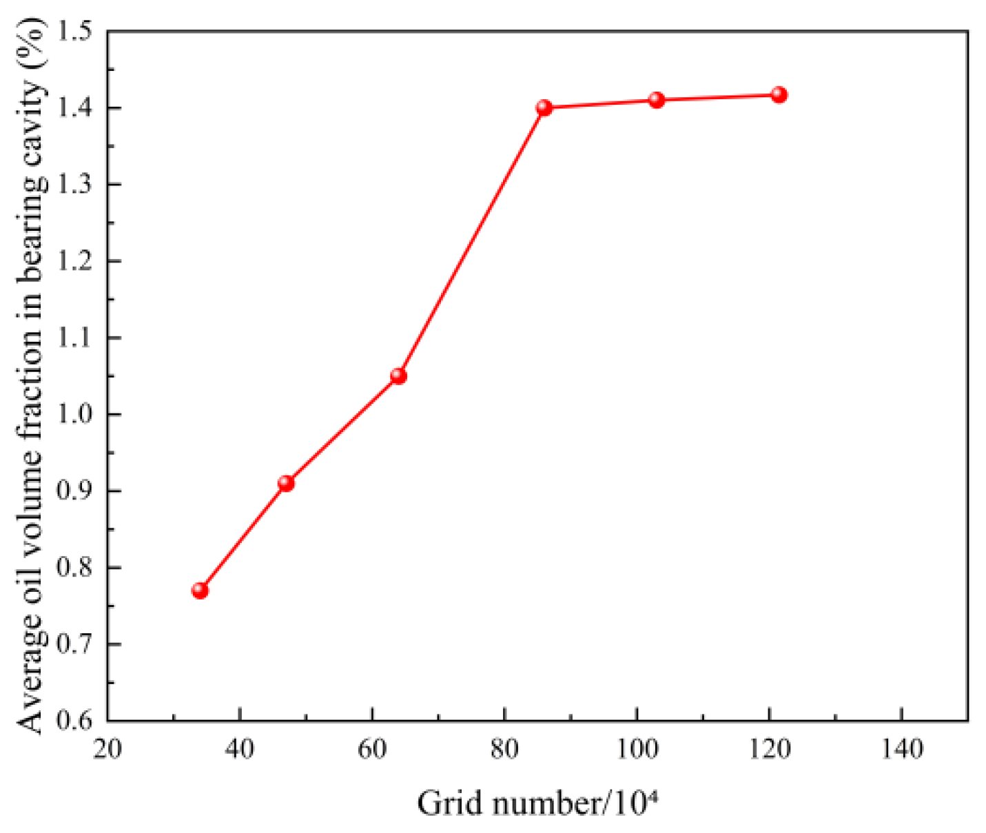
The credibility of the CFD model was evaluated through mesh independence, numerical convergence, and consistency with published observations. The mesh-independence results show that when the cell number reaches 8.4 × 10⁵, further mesh refinement has only a limited effect on the calculated mean oil-phase volume fraction on the cage surface. During the simulations, the residuals, mass-flow balance between the inlet and outlets, and stability of the oil-phase volume-fraction distribution were also monitored. Since the local oil-phase volume fraction on the cage surface inside a high-speed bearing cavity is difficult to measure directly, direct experimental validation was not performed. Instead, the predicted decrease in oil-phase volume fraction with increasing rotational speed and clearance was compared with trends reported in previous oil–air lubrication studies. Therefore, the CFD model is mainly used to analyze the relative variation in the cage-surface lubrication state.
Figure 3 presents the results of the mesh-independence verification. It can be observed that when the number of cells reaches 8.4 × 10⁵, the influence of mesh density on the computed results becomes negligible, while the computational cost remains acceptable. Therefore, a mesh with 8.4 × 10⁵ cells is selected for the subsequent numerical simulations.

2.2. Development of a Dynamic Model for a High-Speed Angular Contact Ball Bearing with Flow-Field-Based Lubrication Parameters

The coupling between the CFD lubrication model and the dynamic model is mainly achieved through the oil-phase volume fraction on the cage surface. CFD simulations are first conducted to obtain the mean oil-phase volume fractions on the inner/outer cage surfaces and end faces under different guiding clearances, pocket clearances, and rotational speeds. The relationships between the oil-phase volume fraction and these parameters are then established using the uniform design and quadratic regression method. In the dynamic calculation, the predicted oil-phase volume fraction is used to determine the equivalent density of the oil–air mixture near the cage surface and further calculate the fluid drag torque acting on the cage, thereby affecting cage slip and whirl response.

2.2.1. Geometric Deformation Relationships of the Bearing

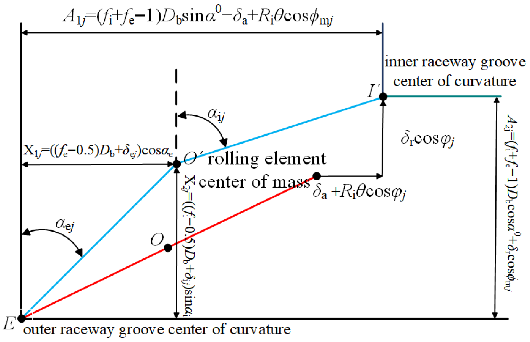
Before loading, no elastic deformation occurs at the contacts between the rolling elements and the raceways. The centroid of the rolling element is collinear with the curvature centers of the inner- and outer-race grooves, and the inner and outer contact angles are identical. The relative positions of these three points are shown in Figure 4. After loading, elastic deformation develops in the contact zones. The curvature center of the outer-race groove remains unchanged, whereas the rolling-element centroid and the curvature center of the inner-race groove deviate from their original positions. According to the geometric compatibility relationships, the following can be obtained:
A 1 j X 1 j 2 + A 2 j X 2 j 2 ( f i 0.5 ) D b + δ i j 2 = 0 X 1 j 2 + X 2 j 2 ( f e 0.5 ) D b + δ e j 2 = 0
where A1j, A2j, X1j, X2j can be obtained from the geometric deformation relationships as follows:
A 1 j = f i + f e 1 D b sin α 0 + δ a + R i θ cos ϕ m j A 2 j = ( f i + f e 1 ) D b cos α 0 + δ r cos ϕ m j X 1 j = ( ( f e 0.5 ) D b + δ e j ) cos α o X 2 j = ( ( f i 0.5 ) D b + δ i j ) sin α i
where the subscript j denotes the rolling-element index; fi and fe are the groove curvature coefficients of the inner and outer raceways, respectively; δij and δoj are the elastic deformation amounts between the rolling element and the inner and outer raceways, respectively; and αi and αo are the inner and outer contact angles after loading.
From Equations (4) and (5), the contact variables can be obtained as follows:
δ i j = A 1 j X 1 j 2 + A 2 j X 2 j 2 ( f i 0.5 ) D b δ e j = X 1 j 2 + X 2 j 2 ( f e 0.5 ) D b
Accordingly, based on Hertzian contact theory, the normal contact forces between the rolling element and the inner and outer raceways can be calculated as:
Q e j = K e j δ e j 1.5 Q i j = K i j δ i j 1.5
where Kij and Kej denote the contact stiffnesses at the inner- and outer-race contacts, respectively. The contact stiffness can be expressed as K = πκE′/3Γ(3ξℜ/Γ)½, where κ is the ellipticity parameter, E′ is the equivalent elastic modulus, and is the equivalent radius of curvature. Γ and ξ are the complete elliptic integrals of the first and second kind, respectively. Detailed calculations can be found in Ref. [20].

2.2.2. Interaction Between the Cage and the Guiding Ring

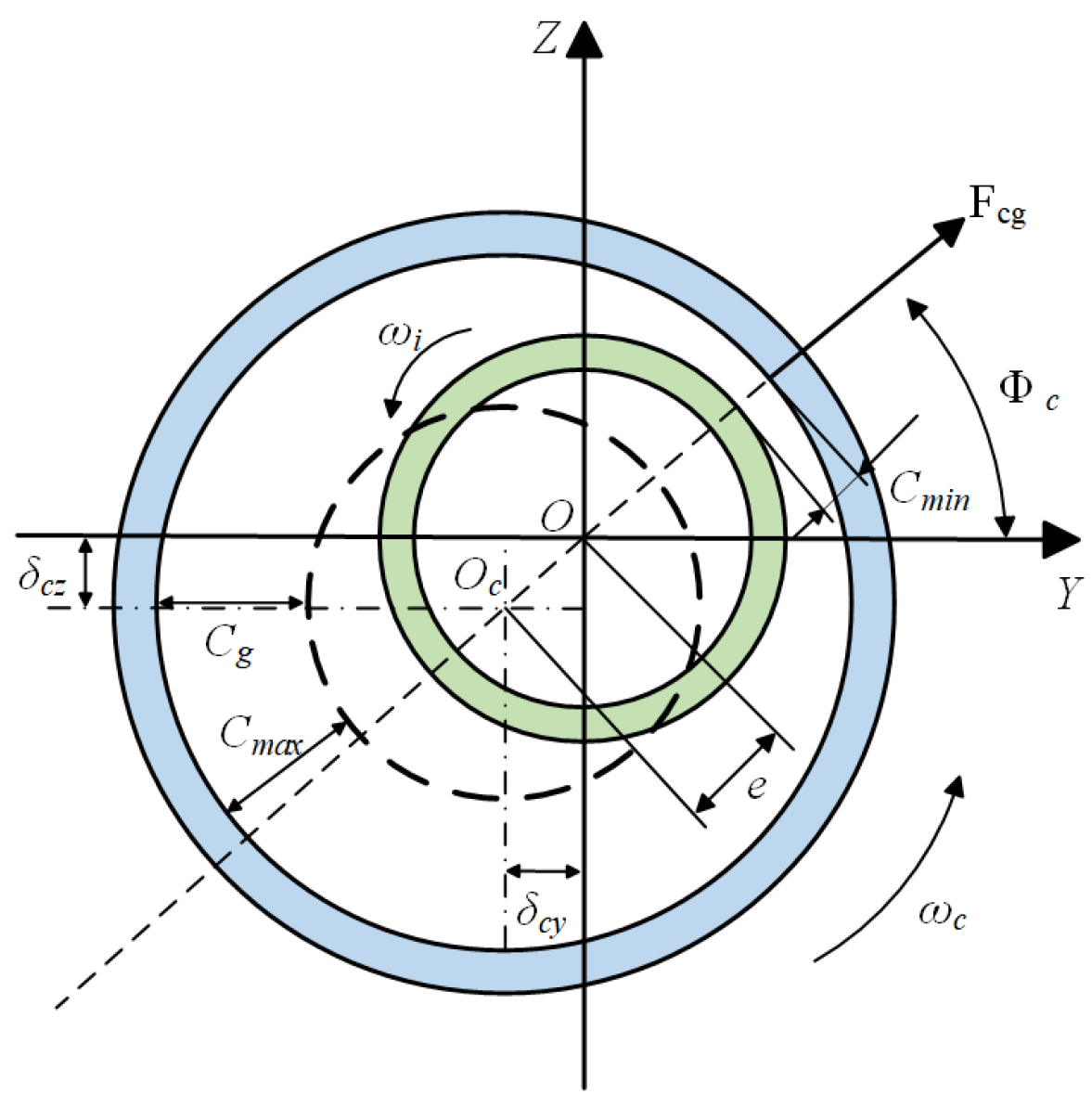
The lubricating oil flowing in the clearance between the guiding ring and the cage generates a hydrodynamic pressure acting on the cage, as shown in Figure 5. In the figure, O and Oc denote the centroid of the inner ring and the rotation center of the cage, respectively; e, Φc, and Cg represent the cage eccentricity, tilt (misalignment) angle, and guiding clearance, respectively. Cmin and Cmax are the minimum and maximum clearances between the cage and the ring, and δcy and δcz are the cage translational displacements in the Y and Z directions, respectively. The cage is inner-ring-guided: the inner ring rotates about the X-axis at an angular speed ωi, and the cage rotates at an angular speed ωc. The cage is subjected to hydrodynamic-lubrication-induced forces Fcg, F’cy, and F’cz, where F’cy and F’cz are the Y- and Z-components of the hydrodynamic pressure force Fcg, respectively.
According to short-bearing lubrication theory, the components of the hydrodynamic pressure force Fcg, i.e., F’cy and F’cz, can be expressed as:
F c z = η o u L 3 ε 2 C g 2 ( 1 ε 2 ) 2
F c y = π η o u L 3 ε 4 C g 2 ( 1 ε 2 ) 1.5
where ηo is the dynamic viscosity of the lubricating oil; L and R1 denote the width and radius of the cage-centering guiding surface, respectively; u is the fluid entrainment drag velocity, given by u = R1(ωi + ωc); and ε is the relative eccentricity, defined as ε = e/Cg.
To transform F’cy and F’cz into the inertial coordinate system, they must be multiplied by the transformation matrix Tc:
T c = sin Φ c cos Φ c cos Φ c sin Φ c
Simplifying Tc[F’cy, F’cz]T yields:
F c g y = sin Φ c η o u L 3 ε 2 c g 2 ( 1 ε 2 ) 2 cos Φ c η o u L 3 ε 4 c g 2 ( 1 ε 2 ) 1.5 F c g z = cos Φ c η o u L 3 ε 2 c g 2 ( 1 ε 2 ) 2 + sin Φ c η o u L 3 ε 4 c g 2 ( 1 ε 2 ) 1.5
Due to the viscosity of the lubricating oil, the fluid exerts a driving torque on the cage surface, denoted as Mcg, which promotes cage rotation.
M c g = 2 π η o V 1 R 1 L / ( C g 1 ε 2 )
where V1 denotes the relative sliding velocity between the cage surface and the guiding ring surface.
V 1 = R 1 ( ω i ω c )

2.2.3. Interaction Between the Oil–Air Mixture and Bearing Components

(1) Interaction between the oil–air mixture and the cage
During operation, the outer surface as well as the upper and lower surfaces of the cage are subjected to resistive drag torques induced by the surrounding lubricating fluid and the oil–air mixture, which can be calculated as follows [21]:
M c l = M c l 1 + M c l 2 = 0.125 η o ρ e 1 S r o 3 ω c 2 + 0.5 ρ e 2 C d r c 5 ω c 2
where Mcl1 and Mcl2 denote the resistive drag torques acting on the upper/lower surfaces and the side surface of the cage, respectively; Cd is a constant, typically taken as 0.04–0.05; S is the area of the upper and lower cage surfaces; rc is the characteristic radius of the cage, with rc5 = ro3(ro2ri2) where ro and ri are the outer and inner radii of the cage, respectively. ρe1 is the density of the oil–air mixture on the cage surface, and ρe2 is the density of the oil–air mixture on the cage end faces; their calculation is given by Equation (13).
It should be noted that the oil-phase volume fraction obtained from CFD is not directly introduced into the dynamic equations as an external load. Instead, it is used as the oil–air mixing coefficient λ to calculate the equivalent density ρe of the oil–air mixture near the cage surface. Specifically, the regression equations predict the mean oil-phase volume fractions on the inner/outer cage surfaces and end faces from the guiding clearance, pocket clearance, and rotational speed, which are then substituted into Equation (13) to determine ρe. This equivalent density is further used in Equation (12) to calculate the fluid drag torques acting on the outer surface and the upper/lower end faces of the cage. Therefore, the coupling between the CFD and dynamic models is mainly realized through “oil-phase volume fraction on the cage surface–equivalent mixture density–fluid drag torque acting on the cage”.
ρ e = ρ o λ 2 / ( 0.4 + 0.6 λ )
where ρo is the density of the lubricating oil at ambient room temperature, and λ is the mixing ratio coefficient of lubricating oil and air.
The relationships between the mean oil-phase volume fraction on the inner and outer cage surfaces and on the two end faces, and the guiding clearance, pocket clearance, and rotational speed are given in Equations (21) and (22).
λ = φ o i l 1 φ o i l
ρ e 1 = ρ o λ 1 2 / ( 0.4 + 0.6 λ 1 ) ρ e 2 = ρ o λ 2 2 / ( 0.4 + 0.6 λ 2 )
(2) Interaction between the oil–air mixture and the rolling elements
According to bearing fluid theory [22], within the bearing cavity, the rolling elements are subjected to the disturbance drag exerted by the oil–air mixture during high-speed motion, which can be expressed as:
F d j = π 32 C D ρ e D b d m ω m j 2
where Cd is the churning stirring coefficient. The drag force Fdj acts opposite to the direction of the rolling element’s linear velocity.

2.2.4. Equations of Motion for the Rolling Elements

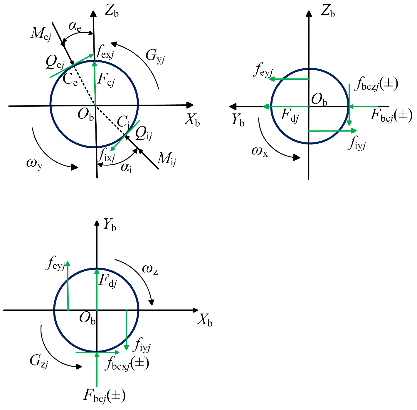
The forces acting on the jth rolling element are illustrated in Figure 6. In the figure, Ci and Ce denote the elliptical contact regions between the rolling element and the inner and outer raceways, respectively; αij and αej are the contact angles at the inner- and outer-race contacts; Qij and Qej are the normal contact forces between the rolling element and the inner and outer raceways; Mij and Mej are the spin-resisting torques acting on the rolling element induced by the lubricant films at the inner- and outer-race contacts; Gyj and Gzj are the gyroscopic moments about the Yb and Zb axes, respectively. fixj, fiyj, fexj, and feyj are the x- and y-components of the traction forces exerted on the rolling element by the inner and outer raceways, respectively. Fbcj and fbcj are the nonlinear normal contact force and the tangential friction force between the rolling element and the cage pocket wall, respectively. Fcj is the centrifugal force acting on the rolling element, and Fdj is the drag force exerted by the oil–air mixture. The drag force is given by Fdj = π/32(Dbdmωmj)2CDρe.
Based on the forces acting on the rolling element, the static equilibrium equations of the rolling element can be written as:
Q i j cos α i j Q e j cos α e j f ix j sin α i j + f ex j sin α e j + F c j f bcz j = 0 Q e j sin α i j Q i j sin α e j f ix j cos α i j + f ex j cos α e j = 0
where the centrifugal force acting on the rolling element is Fcj = 0.5mdmω2mj and m is the mass of the rolling element.
To establish the differential equation governing the rolling element’s spin motion:
I b ω ˙ x j = d m 2 f bcz j f ey cos α e j f iy cos α i j + ( M e j sin α i j M i j sin α e j ) I b ( ω ˙ j y ω m j ω z j ) = d m 2 ( f iy j + f ix j ) I b ( ω ˙ j z ω m j ω y j ) = d m 2 f bcx j f ey sin α e j f iy sin α i j + ( M i j cos α i j M e j cos α e j ) I m ω ˙ m j = d re 2 f ey j + d ri 2 f iy j d m 2 ( F bc j + F d j )
where dri and dre denote the outer and inner diameters of the bearing, respectively; Im is the rolling element’s moment of inertia about the x-axis, given by Im = Ib + 0.25md2m; and Ib is the rolling element’s own spin moment of inertia, Ib = 0.1mD2b.

2.2.5. Equations of Motion for the Cage

Fcgy and Fcgz are the Y- and Z-direction components of the hydrodynamic pressure force Fcg, respectively. Fcbj and fcbj denote the interaction forces between the rolling element and the cage. θmj is the angular position of the jth rolling element, and Φc is the cage tilt angle, defined as Φc = arctan(δcy/δcz). According to the force analysis of the cage, the differential equations governing the cage motion can be written as follows:
F cgy + j = 1 Z n ( f cb j sin θ m j F cb j cos θ m j ) + F mcy = m c δ cy ¨ F cgz + j = 1 Z n ( f cb j cos θ m j F cb j sin θ m j ) + F mcz = m c δ cz ¨ M cg + j = 1 Z n ( f cbj D b 2 + F cb j d m 2 ) M cl = I c θ ¨ c
where mc is the mass of the cage, and Ic is the moment of inertia of the cage. Fmcy and Fmcz are the unbalance forces acting on the cage, which can be expressed as Fmcy = 0.5medmωc2cosΦc, Fmcz = 0.5medmωc2sinΦc, where me is the unbalance mass of the cage.

2.2.6. Equilibrium Equations of the Inner Ring

The equilibrium equations of the inner ring can be written as:
F x = j = 1 Z n cos ϕ m j ( Q i j sin α i j f ix j cos α i j ) F y = j = 1 Z n sin ϕ m j ( Q i j sin α i j f ix j cos α i j ) F z = j = 1 Z n ( Q i j cos α i j f ix j sin α i j ) M y = j = 1 Z n R j sin ϕ m j ( Q i j cos α i j + f ix j sin α i j ) + sin ϕ m j f ix j d ri 2 M z = j = 1 Z n R j cos ϕ m j ( Q i j cos α i j f ix j sin α i j ) cos ϕ m j f ix j d ri 2
where Fx, Fy, Fz, My, and Mz are the external loads acting on the inner-raceway of the bearing, and ϕmj is the angular position of the jth rolling element.

3. Results and Discussion

3.1. Analysis of the Oil-Phase Volume-Fraction Distribution on the Cage Surface

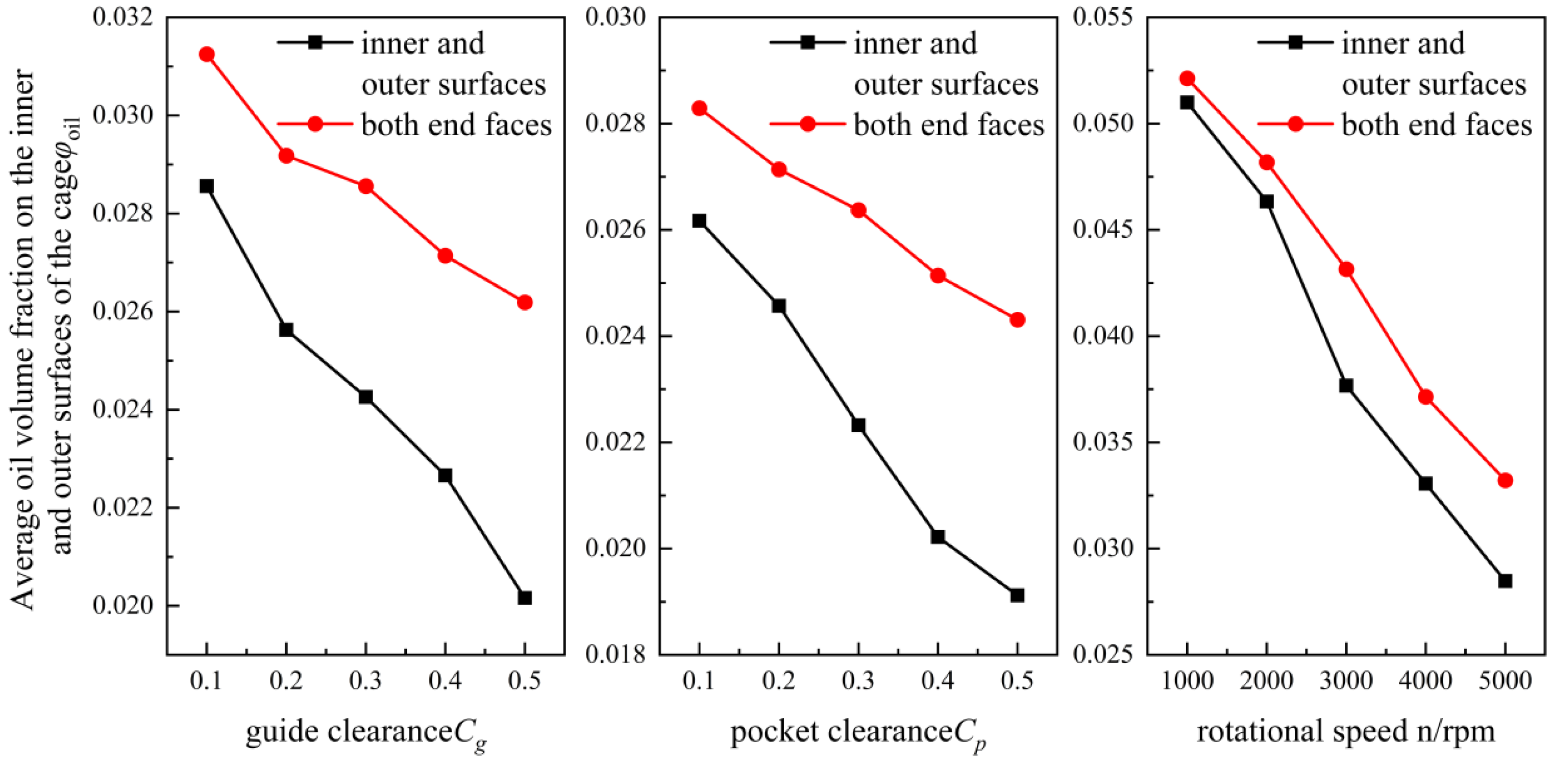
To investigate the effects of guiding clearance, pocket clearance, and rotational speed on the oil-phase volume-fraction distribution on the cage surface, an inner-ring-guided configuration is taken as an example. The influences of guiding clearance (0.1–0.5 mm), pocket clearance (0.1–0.5 mm), and rotational speed (1000–5000 rpm) on the mean oil-phase volume fraction over the inner and outer cage surfaces as well as the two end faces are examined. The results are shown in Figure 7. As can be seen, increasing the guiding clearance reduces the oil-phase volume fraction on both the inner and outer cage surfaces. This is because a larger clearance widens the flow passage, promoting the diffusion and dilution of the oil–air mixture and thereby decreasing the effective oil supply; meanwhile, the enhanced centrifugal effect intensifies radial oil loss, and the continuous oil film tends to break into discrete droplets, ultimately leading to a reduction in the mean oil-phase volume fraction on the cage surfaces. The oil phase on the cage end faces is mainly supplied by axial spreading from the inner/outer diameter surfaces and by axial airflow transport. With an increased guiding clearance, these end-face oil sources are weakened and axial-flow disturbances become stronger; in combination with centrifugal effects, the mean oil-phase volume fraction on the end faces also decreases as the guiding clearance increases. Similarly, increasing the pocket clearance leads to a decrease in the mean oil-phase volume fraction on the inner and outer surfaces as well as on the end faces, because the enlarged pocket clearance facilitates oil overflow and loss under centrifugal action. With increasing rotational speed, the mean oil-phase volume fraction on the inner and outer cage surfaces and on the end faces exhibits an overall downward trend, because the centrifugal force increases markedly and becomes the dominant factor. For the inner and outer surfaces, centrifugal action drives the oil phase radially outward, while the high-speed airflow forms an air curtain that hinders oil entrainment and supply; additionally, strong shear promotes film thinning and rupture, with a more pronounced reduction observed on the inner-diameter surface. For the end faces, oil droplets are less able to remain stably attached under centrifugal action and are more readily flung off; turbulence at the end faces and high-shear axial airflow further aggravate oil stripping, resulting in a continuous decrease in the end-face oil-phase volume fraction.

3.2. Construction of Regression Equations for the Mean Oil-Phase Volume Fraction on the Cage Inner/Outer Surfaces and End Faces

To investigate the effects of guiding clearance, pocket clearance, and rotational speed on the mean oil-phase volume fraction on the inner/outer cage surfaces and the two end faces, a three-factor, eleven-level uniform design is adopted in this study, and regression analysis is performed accordingly. The level intervals for both the guiding clearance and pocket clearance are set to 0.04 mm, and the interval for rotational speed is 400 rpm. Based on the analysis in Section 3.1, the data are subjected to a stepwise quadratic polynomial regression, yielding predictive models for the mean oil-phase volume fraction on the inner and outer cage surfaces and on the two end faces, as given in Equations (21) and (22).
φ o i l 1 = 0.03425 0.08408 x 1 0.08728 x 2 + 3.654 × 10 6 x 3 +               0.05493 x 2 2 9.166 × 10 10 x 3 2 + 0.1492 x 1 x 2 +               0.1026 × 10 4 x 1 x 3 + 1.464 × 10 6 x 2 x 3
φ o i l 2 = 0.01923 0.04047 x 1 0.04782 x 2 + 6.942 × 10 6 x 3               0.03354 x 1 2 1.279 × 10 9 x 3 2 + 0.1206 x 1 x 2 +               5.958 × 10 6 x 1 x 3 + 2.552 × 10 6 x 2 x 3
Physically, the regression equations describe the relationship between the oil-retention capability of the cage surface and the structural clearances and rotational speed. The linear terms represent the dominant effects of each parameter, the quadratic terms describe nonlinear variations caused by oil diffusion, centrifugal oil throw-off, and shear-induced film breakup, and the interaction terms reflect parameter coupling. Since the CFD results show that the oil-phase volume fraction does not vary strictly linearly with clearance and speed, the quadratic polynomial model was adopted to capture the main nonlinear trends with limited samples while avoiding overfitting associated with higher-order models.
Terms with extremely low significance for the dependent variable are eliminated. The regression equations are then evaluated, yielding a multiple correlation coefficient of R = 0.9945. The F-statistic is 22.7035 with a significance level of p = 0.0429, the residual standard deviation is S = 0.0007, and the adjusted correlation coefficient is Ra = 0.9949.
In addition, residual analysis was conducted to further validate the regression model. The results indicate that the residuals are generally small and randomly distributed around zero, without any obvious systematic deviation, suggesting that the proposed regression equations have good fitting accuracy and stability and can be used to characterize the combined effects of guiding clearance, pocket clearance, and rotational speed on the mean oil-phase volume fraction over the cage surfaces.
The proposed regression equations are valid only for the investigated 7224C angular contact ball bearing under the specified oil-inlet velocity, lubricant properties, and boundary conditions, with guiding clearance Cg = 0.1–0.5 mm, pocket clearance Cp = 0.1–0.5 mm, and rotational speed n = 1000–5000 rpm. Outside this range, the oil–air two-phase flow state may change, and the model accuracy cannot be guaranteed. Therefore, the equations should not be extrapolated; for other bearing structures, lubrication schemes, or higher-speed conditions, additional CFD simulations and recalibration of the regression coefficients are required.

3.3. Analysis of Cage Motion Stability

Common indices for evaluating bearing dynamic performance include vibration acceleration, temperature rise, noise, slip ratio, and friction torque. The slip ratio directly reflects the degree of sliding between the rolling elements and the raceways; an excessively high slip ratio intensifies wear, promotes failure, increases vibration and noise, and degrades bearing accuracy and service life. Cage stability can be qualitatively assessed from the cage-centroid trajectory: a single point indicates complete stability; a single circular or periodic circular trajectory corresponds to stable whirl; and polygonal or chaotic trajectories indicate unstable, divergent whirl [23]. Given the importance of the slip ratio and the deviation ratio of the cage-centroid whirling velocity in characterizing bearing dynamics, this study employs these two metrics as key indicators. Under stable operating conditions, the dynamic performance of an inner-ring-guided cage is investigated by varying the guiding clearance, pocket clearance, rotational speed, and external loads. The resulting cage dynamic behavior is then revealed in terms of the slip ratio, centroid trajectory, and whirling-velocity deviation ratio. A one-factor-at-a-time parameter scan was used as a local sensitivity analysis. The guiding clearance, pocket clearance, rotational speed, axial load, and radial load were varied separately while the other parameters were kept unchanged to examine their effects on the cage slip ratio and the deviation ratio of cage-centroid whirling velocity. This method reflects the direct influence of commonly adjusted engineering parameters on cage dynamics, but does not include a global sensitivity analysis based on variance decomposition or Sobol indices. Therefore, the conclusions mainly represent local sensitivity within the investigated parameter ranges.
(1) Cage slip ratio
During bearing operation, the cage is prone to slip, which may lead to bearing failure. The cage slip ratio Δωc is defined as follows:
Δ ω c = | ω ct ω cp | ω ct × 100 %
where ωct is the theoretical cage angular speed, which is related to the inner-race angular speed by ωct = ωi(1 − γ)/2; ωcp is the cage angular speed obtained from the dynamic model; and γ is a dimensionless bearing parameter defined as γ = Dbcosα0/dm.
(2) Deviation ratio of the cage-centroid whirling velocity
When the cage-centroid trajectory exhibits a whirling motion, the stability should be quantitatively evaluated by considering variations in the centroid whirling velocity. In engineering optimization, the deviation ratio of the cage-centroid whirling velocity is commonly used to assess motion stability: a larger value indicates more pronounced fluctuations in the whirling velocity and thus poorer cage stability, whereas a smaller value implies better stability. In this chapter, following the criterion proposed by Ghaisas et al. [24], the deviation ratio is calculated as the ratio of the standard deviation of the centroid velocity to its mean value. The parameter σ can be regarded as a dimensionless coefficient of variation in the cage-centroid whirling velocity, reflecting its fluctuation relative to the mean value. A larger σ indicates poorer cage motion stability, whereas a smaller value indicates smoother whirling motion. Since σ depends on cage structure, guiding mode, lubrication state, and loading condition, no universal instability threshold is defined in this study. Instead, it is used as a relative stability indicator together with the centroid trajectory and slip ratio.
σ v = i = 1 n v i v m 2 / n 1 v m
where vi is the cage-centroid whirling velocity at the ith time instant, and vm is the mean whirling velocity of the centroid.
The cage-centroid trajectory is used to visually describe the motion pattern and convergence characteristics of the cage, but the stability evaluation is not limited to qualitative observation. To improve comparability, the cage slip ratio and the deviation ratio of cage-centroid whirling velocity are also adopted as quantitative indicators, representing the deviation of cage speed from the theoretical orbital speed and the fluctuation of whirling velocity, respectively. Therefore, cage stability is evaluated using both trajectory patterns and quantitative indicators.
In this study, cage instability is evaluated comprehensively using the cage-centroid trajectory, slip ratio, and deviation ratio of centroid whirling velocity rather than a single indicator. When the centroid trajectory changes from a regular convergent annular pattern to an irregular, polygonal, or divergent pattern, accompanied by increases in slip ratio and σ, the cage motion is considered less stable and tends toward instability. This criterion can be used to compare the relative cage stability under different structural parameters and operating conditions.

3.3.1. Effects of Guiding Clearance on Cage Characteristics

To investigate the influence of guiding clearance on cage characteristics, this section considers an axial load of Fa = 5000 N, a radial load of Fr = 10,000 N, and a rotational speed of 5000 rpm. The cage behavior is analyzed for guiding clearances Cg ranging from 0.1 to 0.5 mm with an increment of 0.1 mm.
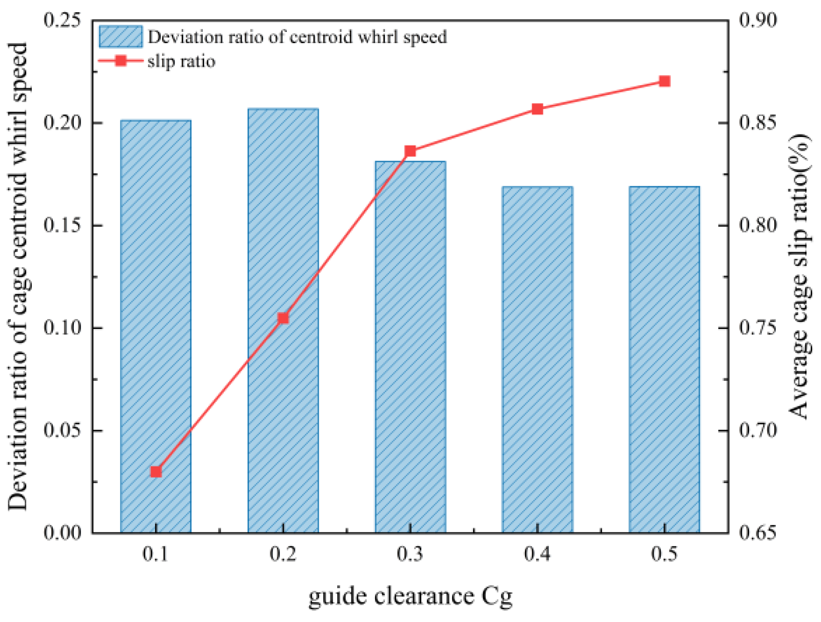
As shown in Figure 8, when the guiding clearance varies from 0.1 to 0.5 mm, the cage slip ratio exhibits an overall increasing trend with increasing clearance. For relatively small clearances (0.1–0.3 mm), the effective contact area at the guiding surface and the corresponding friction force decrease markedly; the reduced driving capability leads to a rapid increase in the slip ratio. When the guiding clearance exceeds 0.3 mm, the reduction in friction force becomes less pronounced, and the improved lubrication space provides a buffering effect through viscous resistance, resulting in a slower growth rate of the slip ratio. Meanwhile, as the guiding clearance increases from 0.1 to 0.5 mm, the deviation ratio of the cage-centroid whirling velocity, σ, decreases overall and gradually stabilizes, indicating that an appropriate increase in guiding clearance can enhance the motion stability of the cage. With a small guiding clearance, the hydrodynamic driving torque tends to be larger, which can exacerbate cage lead/lag behavior, increase impact loads, and thus reduce stability. Nevertheless, a larger guiding clearance is not always beneficial; an excessively large clearance can intensify impacts between the cage and the rolling elements, potentially causing cage fatigue damage [25].
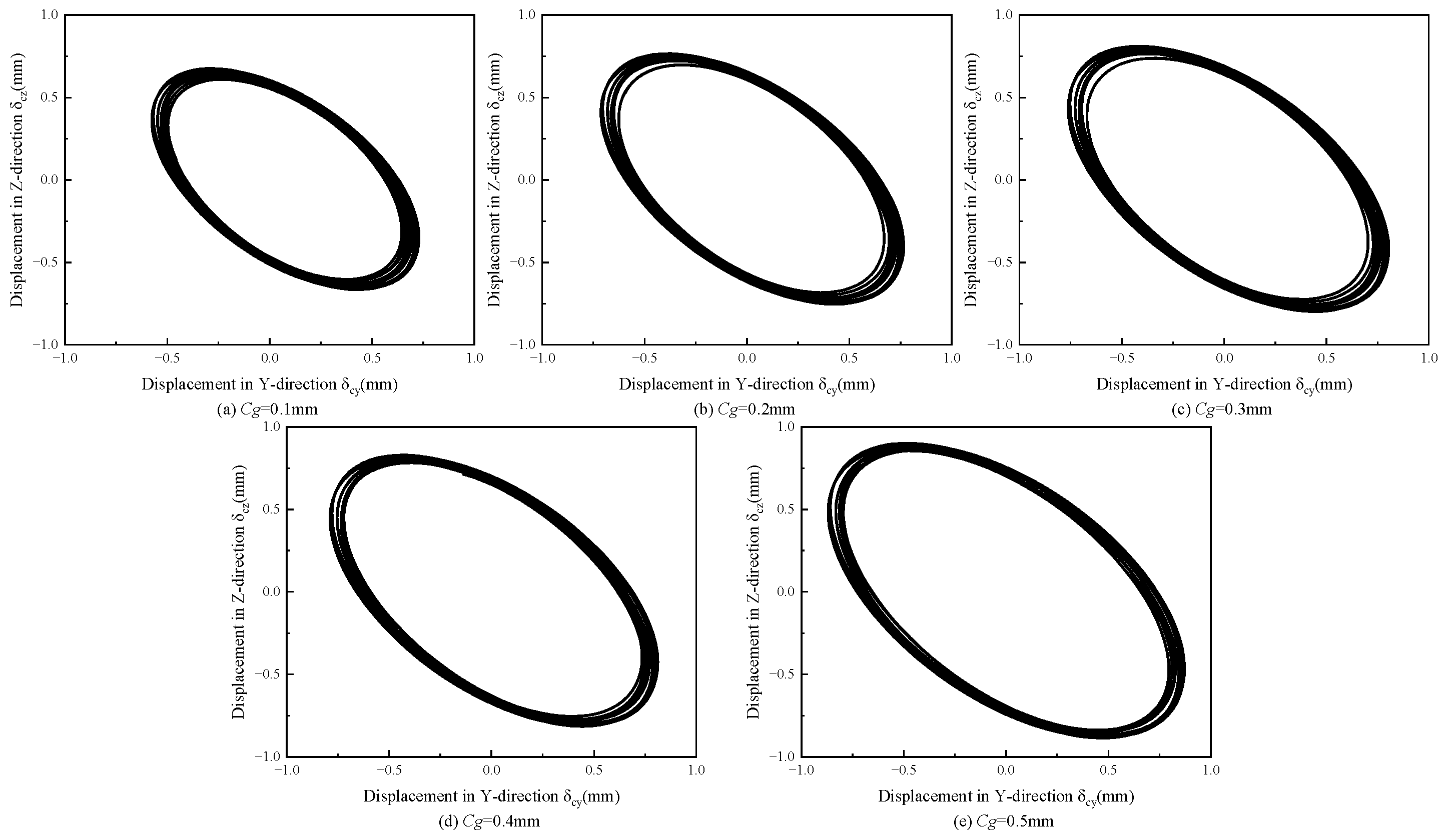
Figure 9 shows the cage motion trajectories of the angular contact ball bearing under different guiding clearances. Under high-speed operating conditions, the cage trajectory forms a regular, convergent annular pattern. As the guiding clearance increases, the radius of the annulus increases while its thickness decreases, indicating reduced trajectory dispersion and improved running stability. These results demonstrate that increasing the guiding clearance is beneficial for enhancing cage stability at high speeds.

3.3.2. Effect of Pocket Clearance on Cage Characteristics

To investigate the running stability of the cage in an angular contact ball bearing under different pocket clearances, this section considers an axial load of Fa = 5000 N, a radial load of Fr = 10,000 N, and a rotational speed of 5000 rpm. The cage behavior is analyzed for pocket clearances Cp ranging from 0.1 to 0.5 mm with an increment of 0.1 mm.
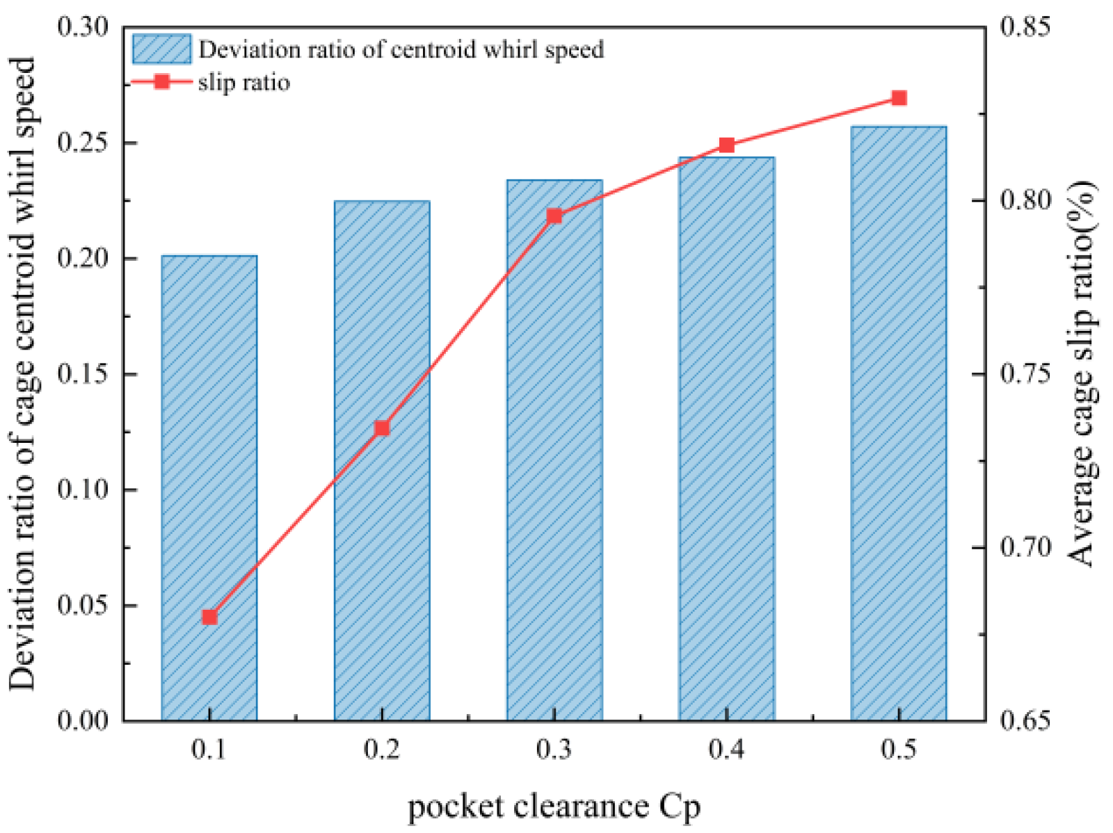
As shown in Figure 10, when the pocket clearance varies from 0.1 to 0.5 mm, the slip ratio increases with increasing clearance. For pocket clearances of 0.1–0.3 mm, the effective contact area between the rolling element and the pocket wall, as well as the impact-induced squeezing force, decreases sharply; the resulting reduction in driving capability causes the slip ratio to rise rapidly. When the pocket clearance exceeds 0.3 mm, the decay of the contact force becomes more gradual, and the improved clearance partially counteracts the tendency toward slip, leading to a slower increase in the slip ratio. Meanwhile, as the pocket clearance increases from 0.1 to 0.5 mm, the deviation ratio of the cage-centroid whirling velocity, σ, exhibits an overall upward trend, indicating that an appropriately smaller pocket clearance can enhance cage motion stability. This is mainly because a larger pocket clearance intensifies collision forces between the rolling elements and the cage, thereby increasing the whirling-velocity deviation ratio.
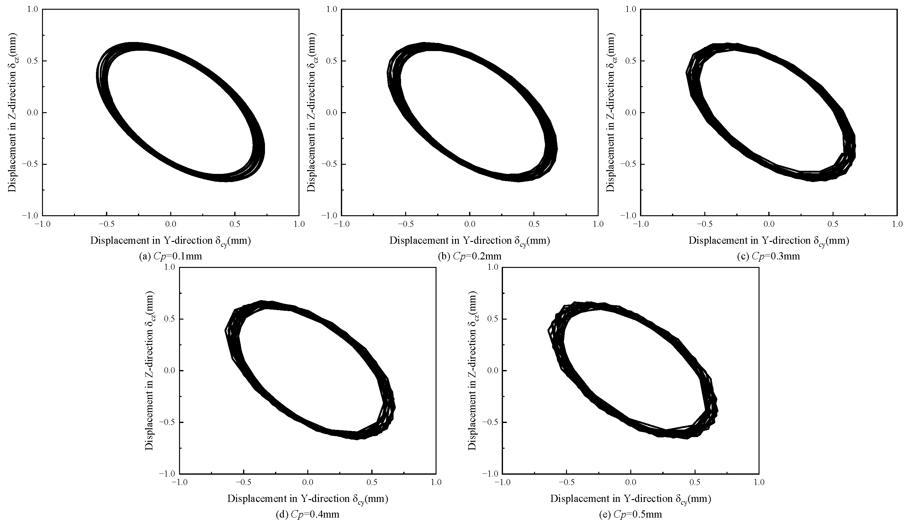
Figure 11 shows the cage motion trajectories of the angular contact ball bearing under different pocket clearances. Under high-speed operating conditions, the cage trajectory exhibits an annular pattern with an approximately constant radius. As the pocket clearance increases, the centroid trajectory becomes progressively more irregular. This is because a larger pocket clearance reduces the contact deformation between the rolling elements and the cage, while intensifying nonlinear contact forces and impact collisions. Therefore, an appropriately smaller pocket clearance is beneficial for improving cage running stability.

3.3.3. Effect of Rotational Speed on Cage Characteristics

To analyze differences in cage motion stability at various rotational speeds (noting that higher speed increases the risk of cage instability), the operating conditions are set as follows: an axial load of Fa = 5000 N and a radial load of Fr = 10,000 N, with rotational speeds of 1000, 2000, 3000, 4000, and 5000 rpm, respectively.
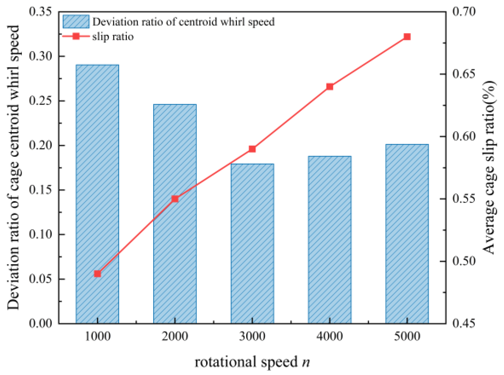
As indicated by the results in Figure 12, increasing rotational speed enhances the centrifugal force of the rolling elements and drives them toward the outer ring. This reduces the friction force at the inner-race contact and the traction exerted by the inner ring, aggravating rolling-element slip and weakening the driving capability acting on the cage, which ultimately increases the mean cage slip ratio. Meanwhile, the deviation ratio of the cage-centroid whirling velocity, σ, decreases gradually as the speed increases from 1000 to 3000 rpm, but begins to rise when the speed exceeds 3000 rpm. In the low-speed range, the guiding effect of hydrodynamic pressure dominates, leading to relatively smooth cage motion. In the high-speed range, impacts between the rolling elements and the cage become more severe, and the impact force becomes the dominant factor, resulting in degraded running stability.
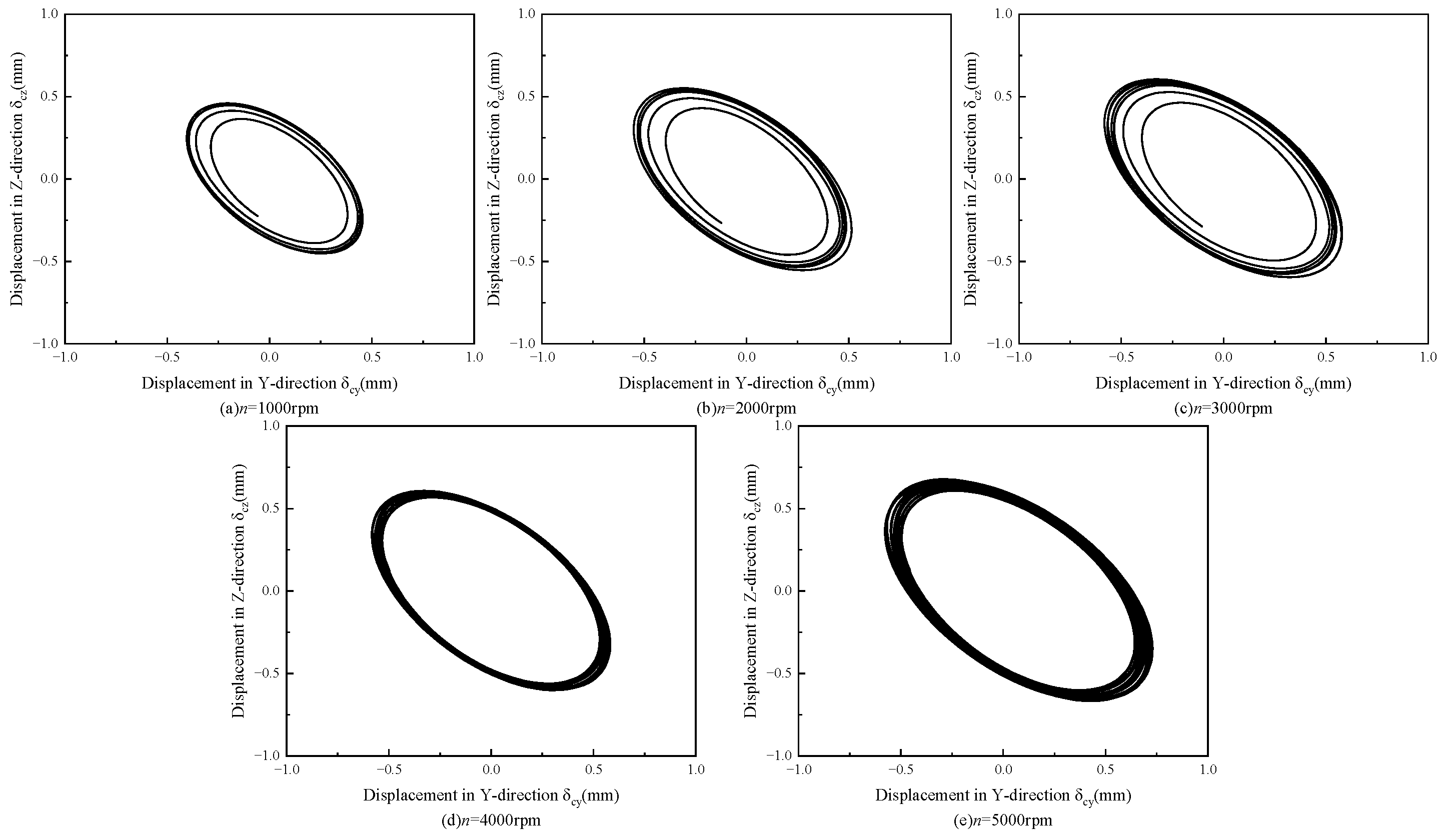
The cage-centroid trajectories at different rotational speeds are shown in Figure 13. As the rotational speed increases, the radius of the cage-centroid trajectory continuously enlarges, and the trajectory exhibits more distinct periodic characteristics. It should be noted that the enhancement of trajectory periodicity does not necessarily indicate a reduction in the fluctuation of the centroid whirling velocity. When the rotational speed exceeds 3000 rpm, the deviation ratio of the centroid whirling velocity increases instead because of the enlarged trajectory radius and the intensified collisions between the rolling elements and the cage.

3.3.4. Effect of Load on Cage Characteristics

To investigate the cage characteristics of the angular contact ball bearing under different loads, the rotational speed is set to ωi = 5000 rpm. With the radial load fixed at Fr = 10,000 N, the cage behavior is analyzed for axial loads Fa = 1000, 2000, 3000, 4000, and 5000 N. In addition, with the axial load fixed at Fa = 5000 N, the cage behavior is analyzed for radial loads Fr = 0, 2000, 4000, 6000, 8000, and 10,000 N.
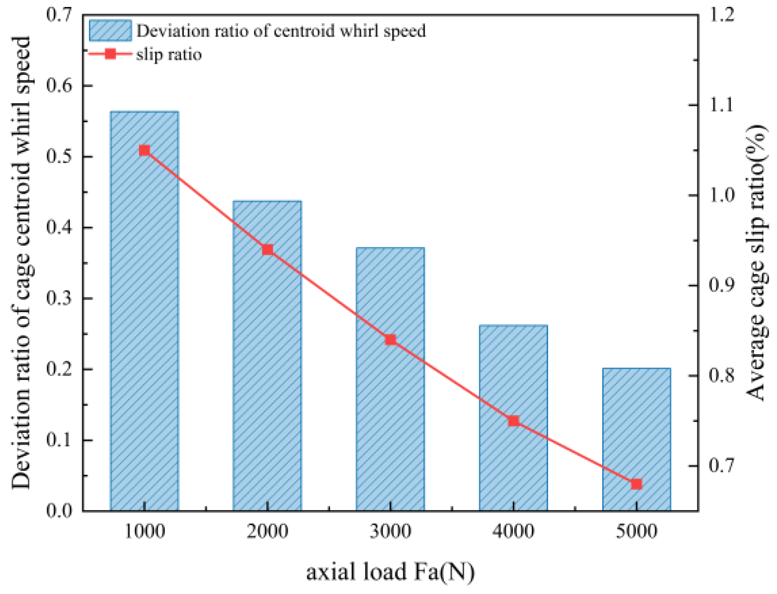
As shown in Figure 14, the mean cage slip ratio decreases with increasing axial load. A higher axial load increases the contact load and traction force between the rolling elements and the raceways, thereby increasing the cage angular speed and reducing the mean slip ratio. Meanwhile, the deviation ratio of the cage-centroid whirling velocity, σ, also decreases as the axial load increases. The two metrics exhibit a negative correlation, indicating that increasing the axial load can effectively suppress cage speed fluctuations and improve running smoothness. With a larger axial load, the rolling elements engage the raceways more tightly and receive sufficient traction, resulting in more stable rolling-element motion; consequently, impacts and collisions between the rolling elements and the cage are mitigated, which enhances cage running stability.
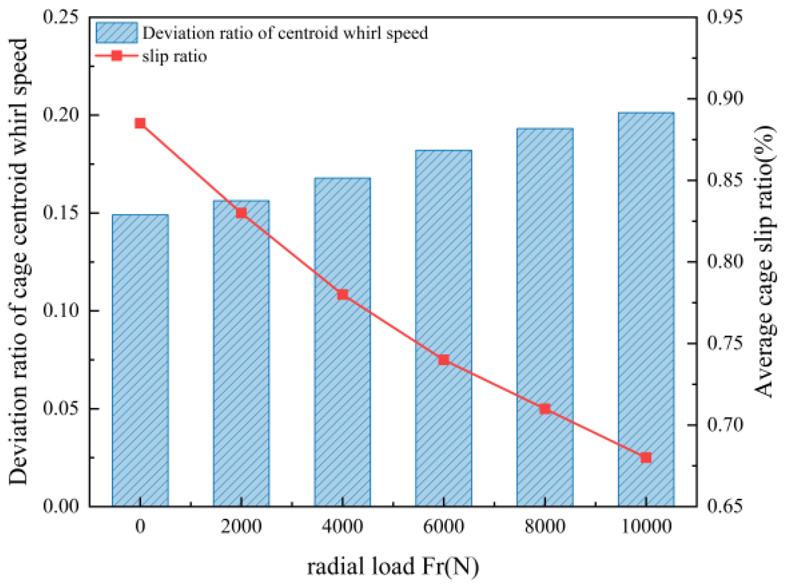
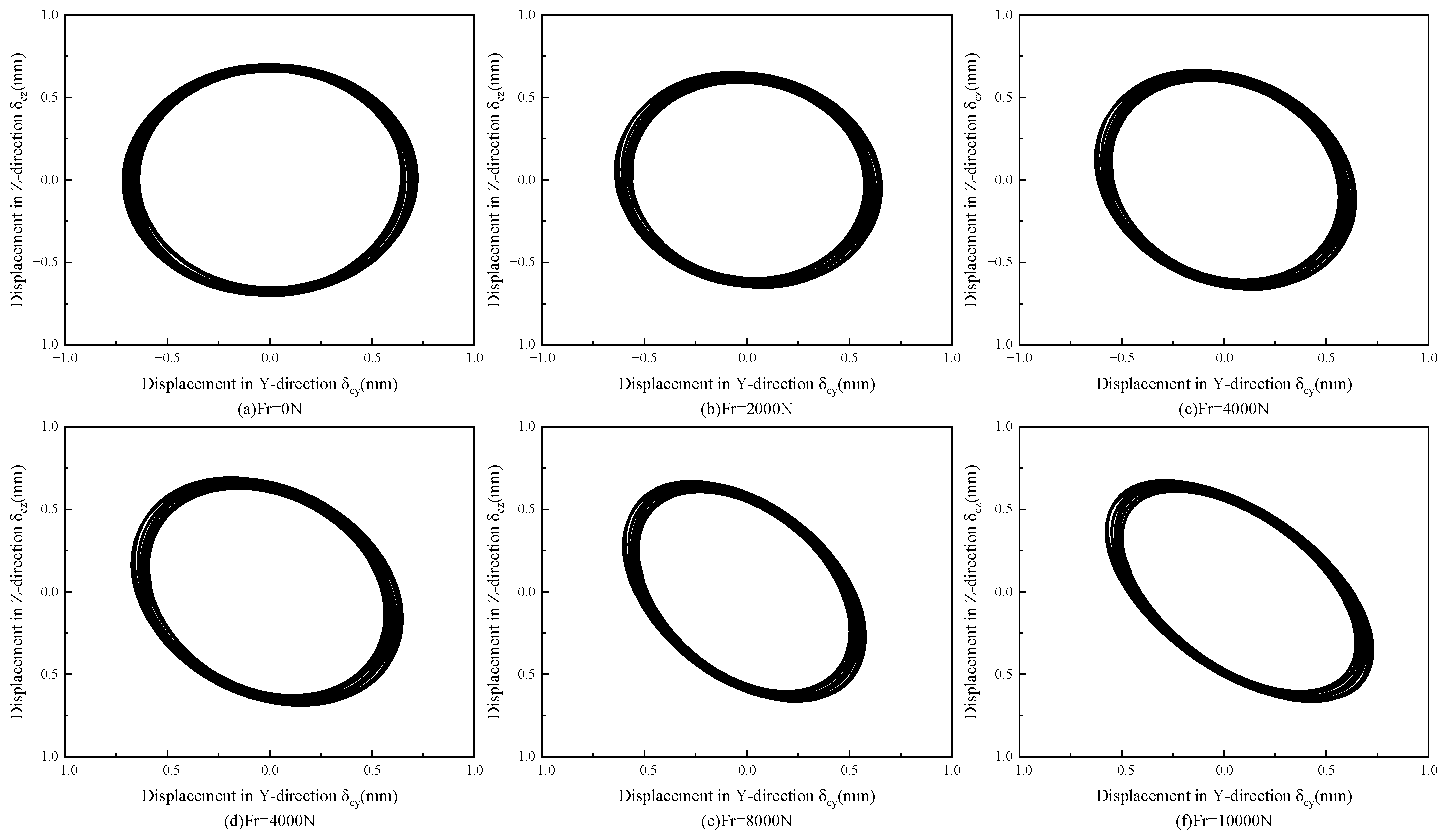
As shown in Figure 15, the mean cage slip ratio decreases with increasing radial load. A higher radial load increases the normal contact pressure between the rolling elements and the raceways in the load zone, thereby strengthening the traction force exerted by the raceways. This enhances the driving effect on the cage, causing the cage speed to approach the theoretical revolution speed and ultimately reducing the slip ratio. Meanwhile, the deviation ratio of the cage-centroid whirling velocity, σ, exhibits an overall increasing tendency with radial load, indicating degraded cage running stability. With increasing radial load, the contact-load distribution among rolling elements becomes more non-uniform, leading to larger differences in traction and more pronounced speed fluctuations. Consequently, impacts and collisions between the rolling elements and the cage become more frequent and severe, which undermines cage stability.
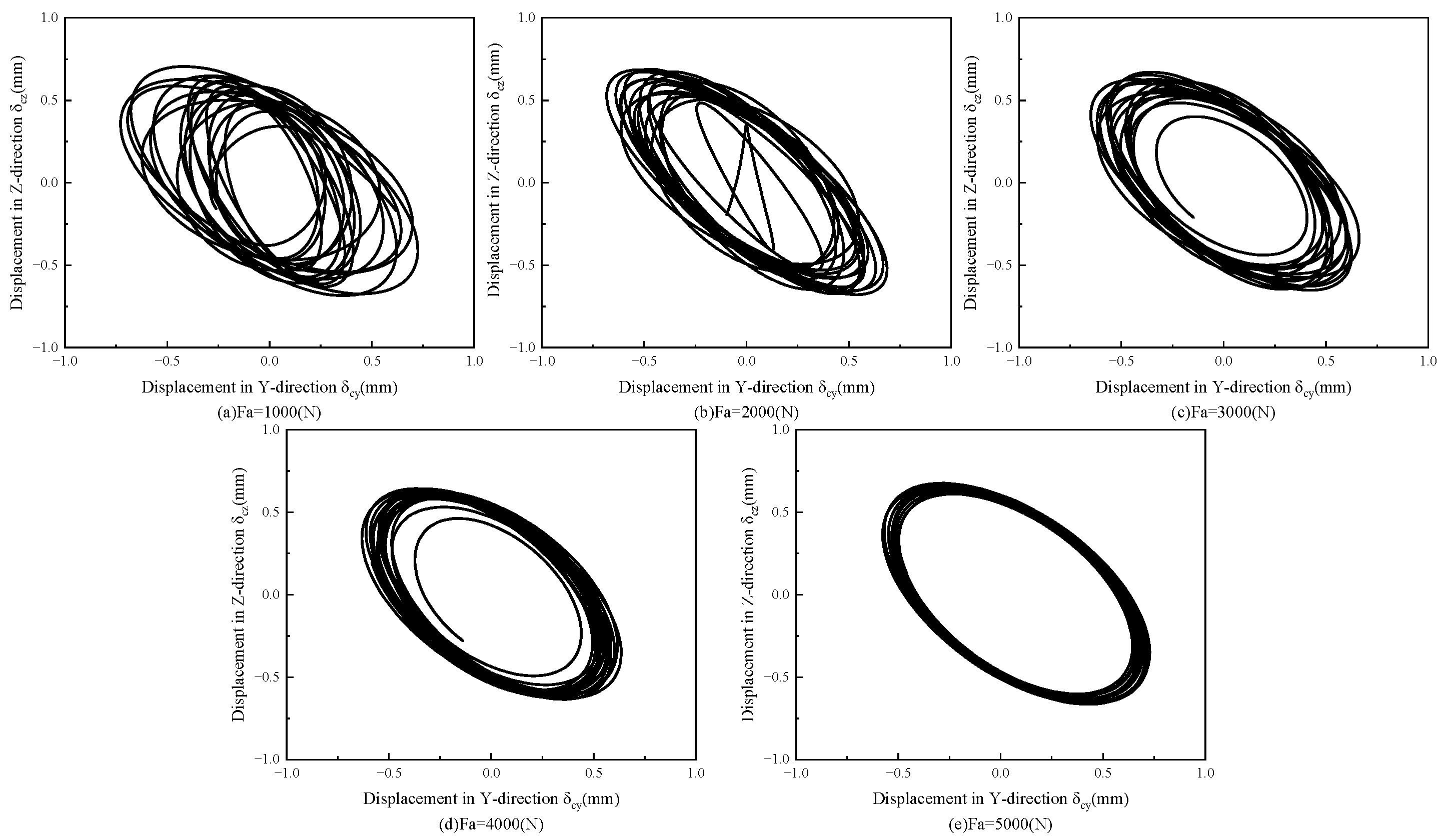
As shown in Figure 16, the cage-centroid trajectories differ under different axial loads. With increasing axial load, the centroid trajectory evolves from a disordered pattern toward a more regular one, while the radius of the annular trajectory remains nearly unchanged. This indicates that increasing the axial load helps enhance cage stability under high-speed operation. The cage-centroid trajectories under different radial loads are presented in Figure 17. As the radial load increases, the centroid trajectory gradually changes from a circular shape to an inclined elliptical one, and the inclination angle increases with load. This is attributed to the radial load inducing periodic fluctuations in the rolling-element rotational speed, which in turn affects the dynamic stability of the cage [26].
In terms of computational cost, the main burden of the proposed method lies in the CFD solution of the bearing-cavity flow field, with approximately 8.4 × 10⁵ cells used to calculate the cage-surface oil-phase volume fraction under different clearance and speed combinations. Once the regression equations are established, repeated CFD simulations are not required for each operating condition. Instead, the oil-phase volume fraction can be predicted from the structural parameters and rotational speed and then used to calculate the equivalent mixture density near the cage surface and the fluid drag torque acting on the cage. Therefore, this method reduces repeated computational cost in cage-parameter optimization and operating-condition matching while retaining the ability to characterize the lubrication state.
The present results are generally consistent with previous studies on cage dynamics and oil–air lubrication. Previous studies have shown that cage instability is related to ball-pocket friction, impact, and fluctuations in cage whirl velocity. In this study, the increase in the deviation ratio of cage-centroid whirling velocity with enlarged pocket clearance and radial load also reflects the influence of ball–cage interaction on stability. Meanwhile, the decrease in oil-phase volume fraction with increasing rotational speed agrees with the reported effect of high-speed rotation in enhancing centrifugal oil throw-off and airflow shear. Compared with previous studies, this work further introduces the CFD-derived oil-phase volume fraction on the cage surface into the dynamic model through the equivalent mixture density, enabling the influence of lubrication-state variation on cage slip and whirl stability to be analyzed.
The combined effects of the investigated parameters indicate that cage stability is mainly governed by the lubrication state, rolling-element traction, and ball–cage collision. Increased rotational speed and enlarged clearances weaken the oil-retention capability on the cage surface and change the fluid drag torque acting on the cage. Axial and radial loads affect the traction effect by changing the contact pressure between the rolling elements and raceways, while pocket clearance and radial load further influence ball–cage collision. Therefore, a reduced slip ratio does not necessarily indicate improved whirl stability, and cage stability should be evaluated by considering lubrication state, traction effect, collision behavior, and quantitative stability indicators together.

4. Conclusions

This study focuses on the 7224C high-speed angular contact ball bearing used in multi-wire cutting machines. A combination of the VOF multiphase-flow method and the RNG k-ε turbulence model was employed to simulate the bearing cavity flow field. The effects of the guide clearance, pocket clearance, and rotational speed on the oil-phase volume fraction at the cage surface were analyzed. Additionally, a bearing dynamics model was established to investigate the influence of guide clearance, pocket clearance, and operating conditions on cage stability. The following key conclusions were drawn:
(1)
An increase in the guiding clearance, pocket clearance, and rotational speed leads to a reduction in the oil volume fraction on the cage surface. This is mainly because larger clearances weaken the local oil retention capacity, while under high-speed operating conditions, centrifugal effects and high-shear airflow further intensify oil film breakup and oil throw-off.
(2)
Increasing the guiding clearance, pocket clearance, and rotational speed results in a higher cage slip ratio, whereas increasing the axial and radial loads reduces the slip ratio. The former is mainly attributed to the weakened driving effect of the rolling elements on the cage, while the latter enhances the contact pressure and traction capacity between the rolling elements and raceways, causing the cage speed to approach the theoretical orbital speed more closely.
(3)
Moderate increase in the guiding clearance and axial load helps reduce fluctuations in cage whirl velocity and improve operational stability. In contrast, an excessively large pocket clearance and an overly high radial load intensify ball–cage collisions and aggravate the non-uniformity of load distribution, thereby reducing cage stability. Meanwhile, the effect of rotational speed on stability is non-monotonic. Within a relatively low speed range, the fluid-guiding effect is dominant and cage stability can be improved. However, as the speed increases further, collision effects become stronger, leading to a deterioration in cage stability.

Author Contributions

Z.L., T.H., Y.Z. and J.Z. performed the data analysis; Z.L. performed the formal analysis; Z.L. performed the validation; Z.L. and Y.Z. wrote the manuscript. All authors have read and agreed to the published version of the manuscript.

Funding

This work was supported by the Guizhou Provincial Key Laboratory of Mountainous Intelligent Agricultural Machinery (Qiankehe Platform ZSYS [2025]013), the National Natural Science Foundation of China (Grant No. 52505064), the National Key Laboratory of Science and Technology on Advanced Light-duty Gas-turbine (GZJJ-KF-2025-01), the Research and Practice Innovation Program for Graduate Students in Jiangsu Province (Grant No. KYCX25_1399), and the open project of Key Laboratory of Agricultural Equipment Technology for Hilly and Mountainous Areas, Ministry of Agriculture and Rural Affairs (No. 2025QSNZ05). In addition, the authors declare that there is no conflict of interest regarding the publication of this article.

Institutional Review Board Statement

Not applicable.

Informed Consent Statement

Not applicable.

Data Availability Statement

The original contributions presented in this study are included in the article. Further inquiries can be directed to the corresponding author.

Conflicts of Interest

The authors declare no conflicts of interest.

References

  1. Liu, Q.; Yan, D.; Lu, B.; Sun, Z.; Li, L. Algorithms for Monitoring Large and Deep Wear Failures of Yaw Bearing Races in Wind Turbines. Eksploat. I Niezawodn. Maint. Reliab. 2025, 28, 207795. [Google Scholar] [CrossRef] [Scilit]
  2. Kingsbury, E.P. Torque Variations in Instrument Ball Bearings. A S L E Trans. 1965, 8, 435–441. [Google Scholar] [CrossRef] [Scilit]
  3. Jiang, Y.; Deng, S. Nonlinear Dynamic Model of Ball Bearings Including All of Bearing Parts with Full Degrees-of-Freedom and Its Advancement Compared to Past Dynamic Models. J. Comput. Nonlinear Dyn. 2026, 21, 011003. [Google Scholar] [CrossRef] [Scilit]
  4. Zhang, S.; Song, B.; Wang, Z.; Bai, X.; Su, Z. Effects of Cage Pocket Wear and Thermal Expansion on the Nonlinear Dynamics of Ceramic Bearings. J. Mech. Sci. Technol. 2026, 40, 61–72. [Google Scholar] [CrossRef] [Scilit]
  5. Wang, H.; Ji, X.; Li, Z.; Wang, C.; Yang, L. Effect of Misalignment on Cage Dynamics and Ball Slip of Double-Row Angular Contact Ball Bearings under Different Configurations. J. Tribol. 2026, 148, 072602. [Google Scholar] [CrossRef] [Scilit]
  6. Qiu, L.; Chen, X.; Shen, X. Modeling of Multibody Lubrication Dynamics in Cylindrical Roller Bearings. Tribol. Trans. 2024, 68, 12–27. [Google Scholar] [CrossRef] [Scilit]
  7. Gupta, P.K. Modeling of Instabilities Induced by Cage Clearances in Ball Bearings. Tribol. Trans. 1991, 34, 93–99. [Google Scholar] [CrossRef] [Scilit]
  8. Gupta, P.K. Cage Unbalance and Wear in Ball Bearings. Wear 1991, 147, 93–104. [Google Scholar] [CrossRef] [Scilit]
  9. Liu, X.; Deng, S.; Teng, H. Dynamic Stability Analysis of Cages in High-Speed Oil-Lubricated Angular Contact Ball Bearings. Trans. Tianjin Univ. 2011, 17, 20–27. [Google Scholar] [CrossRef] [Scilit]
  10. Ye, Z.H.; Wang, L.Q. Cage Instabilities in High-Speed Ball Bearings. Appl. Mech. Mater. 2013, 278–280, 3–6. [Google Scholar] [CrossRef] [Scilit]
  11. Niu, L.; Cao, H.; He, Z.; Li, Y. An Investigation on the Occurrence of Stable Cage Whirl Motions in Ball Bearings Based on Dynamic Simulations. Tribol. Int. 2016, 103, 12–24. [Google Scholar] [CrossRef] [Scilit]
  12. Zhang, T.; Chen, X.; Gu, J.; Wang, Z. Influences of Preload on the Friction and Wear Properties of High-Speed Instrument Angular Contact Ball Bearings. Chin. J. Aeronaut. 2017, 31, 597–607. [Google Scholar] [CrossRef] [Scilit]
  13. Pan, C.; Li, S.; Zhang, J. Review of Research on Dynamic Characteristics of Rolling Bearing Cages. Recent Pat. Eng. 2025, 19, e041023221574. [Google Scholar] [CrossRef] [Scilit]
  14. Chen, S.; Chen, X.; Zhang, T.; Li, Q.; Gu, J. Cage Motion Analysis in Coupling Influences of Ring Guidance Mode and Rotation Mode. J. Adv. Mech. Des. Syst. Manuf. 2019, 13, JAMDSM0054. [Google Scholar] [CrossRef] [Scilit]
  15. Bao, H.; Hou, X.; Lu, F. Analysis of Oil-Air Two-Phase Flow Characteristics inside a Ball Bearing with Under-Race Lubrication. Processes 2020, 8, 1223. [Google Scholar] [CrossRef] [Scilit]
  16. Wu, W.; Hu, C.; Hu, J.; Yuan, S. Jet Cooling for Rolling Bearings: Flow Visualization and Temperature Distribution. Appl. Therm. Eng. 2016, 105, 217–224. [Google Scholar] [CrossRef] [Scilit]
  17. Peterson, W.; Russell, T.; Sadeghi, F.; Berhan, M.T.; Stacke, L.-E.; Ståhl, J. A CFD Investigation of Lubricant Flow in Deep Groove Ball Bearings. Tribol. Int. 2021, 154, 106735. [Google Scholar] [CrossRef] [Scilit]
  18. Vivarelli, G.; Qin, N.; Shahpar, S. A Review of Mesh Adaptation Technology Applied to Computational Fluid Dynamics. Fluids 2025, 10, 129. [Google Scholar] [CrossRef] [Scilit]
  19. Yang, H.; Liu, Q.; Deng, S. Dynamic Characteristic Analysis of Angular Contact Ball Bearings with Two-Piece Inner Rings in Aero-Engine Main Shafts under Unsteady-State Conditions. Lubricants 2025, 13, 249. [Google Scholar] [CrossRef] [Scilit]
  20. Harris, T.A.; Kotzalas, M.N. Rolling Bearing Analysis—2 Volume Set; Informa: London, UK, 2006. [Google Scholar] [CrossRef] [Scilit]
  21. Morales-Espejel, G.E.; Wemekamp, A.W. An engineering drag losses model for rolling bearings. Proc. Inst. Mech. Eng. Part J J. Eng. Tribol. 2023, 237, 415–430. [Google Scholar] [CrossRef] [Scilit]
  22. Gao, W.; Li, Y.; Li, C.; Xu, Y.; Liu, Z. Numerical Prediction of Drag Force on Spherical Elements inside High-Speed Ball Bearing with Under-Race Lubrication. Mech. Syst. Signal Process. 2025, 224, 112024. [Google Scholar] [CrossRef] [Scilit]
  23. Kingsbury, E.; Walker, R. Motions of an unstable retainer in an instrument ball bearing. J. Tribol. 1994, 116, 202–208. [Google Scholar] [CrossRef] [Scilit]
  24. Ghaisas, N.; Wassgren, C.R.; Sadeghi, F. Cage instabilities in cylindrical roller bearings. J. Tribol. 2004, 126, 681–689. [Google Scholar] [CrossRef] [Scilit]
  25. Li, Q.; Ning, J.; Liang, H.; Yang, M. High-Speed Bearing Reliability: Analysis of Tapered Roller Bearing Performance and Cage Fracture Mechanisms. Metals 2025, 15, 592. [Google Scholar] [CrossRef] [Scilit]
  26. Fang, B.; Li, M.; Zhang, J.; Yan, K.; Hong, J. Comprehensive Theoretical and Experimental Study on the Transient Slip Behaviors of the Roller and Cage within the Radial Loaded Cylindrical Roller Bearing. Mech. Syst. Signal Process. 2025, 235, 112887. [Google Scholar] [CrossRef] [Scilit]
Figure 1. Schematic diagram of the cage structure.
Coatings 16 00598 g001
Figure 2. Fluid domain and mesh model inside the bearing cavity.
Coatings 16 00598 g002
Figure 3. Mesh independence verification of the fluid domain model in the bearing chamber.
Coatings 16 00598 g003
Figure 4. Geometric relationship between rolling elements and inner and outer raceways of the bearing.
Coatings 16 00598 g004
Figure 5. Interaction between the inner ring and the cage.
Coatings 16 00598 g005
Figure 6. Force analysis of rolling elements.
Coatings 16 00598 g006
Figure 7. Effects of guide clearance, pocket clearance and rotational speed on oil volume fraction on cage surface.
Coatings 16 00598 g007
Figure 8. Effects of guide clearance on cage slip ratio and centroid whirl velocity deviation ratio.
Coatings 16 00598 g008
Figure 9. Variation in cage trajectory with guide clearance.
Coatings 16 00598 g009
Figure 10. Effects of pocket clearance on cage slip ratio and centroid whirl velocity deviation ratio.
Coatings 16 00598 g010
Figure 11. Variation in cage-centroid trajectory with pocket clearance.
Coatings 16 00598 g011
Figure 12. Effects of rotational speed on cage slip ratio and centroid whirl velocity deviation ratio.
Coatings 16 00598 g012
Figure 13. Variation in cage trajectory with bearing rotational speed.
Coatings 16 00598 g013
Figure 14. Effects of axial load on cage slip ratio and centroid whirl velocity deviation ratio.
Coatings 16 00598 g014
Figure 15. Effects of radial load on cage slip ratio and centroid whirl velocity deviation ratio.
Coatings 16 00598 g015
Figure 16. Variation in cage trajectory with axial load.
Coatings 16 00598 g016
Figure 17. Variation in cage trajectory with radial load.
Coatings 16 00598 g017
Table 1. Bearing structural parameters.
Structural ParametersValuesStructural ParametersValues
Inner diameter dri (mm)120Cage inner diameter Dci (mm)152
Outer diameter dre (mm)215Cage outer diameter Dce (mm)168
Ball diameter Db (mm)25.4Guide land diameter Dig (mm)150.3
Number of balls N18Cage width Bc (mm)34
Pitch circle diameter dm (mm)167.5Guide land width Bg (mm)4.3
Bearing width B (mm)40Cage pocket clearance Cp (mm)0.1–0.5
Contact angle α (°)15Cage guiding clearance Cg (mm)0.1–0.5
Table 2. Basic physical parameters of lubricating oil and air.
ParametersAirLubricating Oil
Density (kg∙m−3)1.225875
Dynamic viscosity (Pa∙s)1.789 × 10−50.04025
Disclaimer/Publisher’s Note: The statements, opinions and data contained in all publications are solely those of the individual author(s) and contributor(s) and not of MDPI and/or the editor(s). MDPI and/or the editor(s) disclaim responsibility for any injury to people or property resulting from any ideas, methods, instructions or products referred to in the content.