Article

Study on the Sealing Performance and Structural Optimization of a Tesla-Valve-Type End-Face Groove Self-Pumping Hydrodynamic Mechanical Seal

1
College of Mechanical and Electronic Engineering, Nanjing Forestry University, Nanjing 210037, China
2
Department of Artificial Intelligence, Shanxi Polytechnic College, Taiyuan 030000, China
*
Author to whom correspondence should be addressed.
Coatings 2026, 16(5), 565; https://doi.org/10.3390/coatings16050565
Submission received: 7 April 2026 / Revised: 23 April 2026 / Accepted: 6 May 2026 / Published: 8 May 2026

Highlights

What are the main findings?
  • A novel self-pumping hydrodynamic mechanical seal with Tesla-valve-type face grooves was proposed, and its numerical model was established. The proposed structure formed a self-pumping circulation and generated multiple local high-pressure regions, which enhanced the hydrodynamic effect and improved the fluid-film stiffness.
  • The leakage rate was not significantly affected by the diversion angle, whereas the fluid-film stiffness increased with increasing diversion angle.
  • The leakage rate was also insensitive to the valve clearance, while the fluid-film stiffness decreased with increasing valve clearance.
  • Multi-objective optimization showed that the optimal structural parameters were a groove depth of 10.02 μm, a diversion angle of 50.2°, a valve clearance of 0.12 mm, and a groove width of 0.45 mm, providing a better compromise between low leakage and high fluid-film stiffness.
What are the implications of the main findings?
  • The Tesla-valve-type groove provides a feasible structural strategy for improving the stiffness of self-pumping mechanical seals without significantly increasing leakage
  • Increasing the diversion angle is beneficial for enhancing fluid-film stiffness, whereas excessive valve clearance should be avoided in practical design.
  • The optimized parameter combination provides theoretical guidance for the structural design and engineering application of self-pumping hydrodynamic mechanical seals.

Abstract

Based on the rectifying conduction principle of the Tesla valve, a self-pumping hydrodynamic mechanical seal with Tesla valve-shaped face grooves was proposed, and its corresponding computational model was established. Numerical simulations were conducted to investigate the effects of the Tesla valve diversion angle and valve clearance on the sealing performance of the proposed structure. Taking the leakage rate and liquid film stiffness as the target performance indices, a predictive model was developed by combining uniform experimental design with multiple regression analysis. Subsequently, the NSGA-II (Non-dominated Sorting Genetic Algorithm II) genetic algorithm was employed for bi-objective optimization to obtain the Pareto-optimal solution set, and the TOPSIS (Technique for Order Preference by Similarity to Ideal Solution) method was further applied to identify the optimal combination of structural parameters under specified weighting coefficients. The results indicate that the leakage rate is not significantly affected by variations in the diversion angle or valve clearance, whereas the liquid film stiffness increases with increasing diversion angle and decreases with increasing valve clearance. Multi-objective optimization successfully identified an optimal parameter combination that improves the overall sealing performance of the proposed structure. This study provides a novel perspective and theoretical basis for innovation in face structure and for the performance optimization of self-pumping mechanical seals.

1. Introduction

Non-contact mechanical seals operate by generating a very thin lubricating film between the rotating and stationary faces through hydrodynamic effects under steady working conditions, thereby separating the two faces and reducing contact wear, which contributes to an extended service life [1]. Owing to this advantage, they have been widely used in petroleum, chemical, and nuclear power industries [2,3]. Since the structural parameters of face grooves play a crucial role in sealing performance [4], extensive studies have been conducted on the structural optimization of seal rings and the optimization of groove parameters. At present, conventional mechanical seals generally depend on complicated barrier-fluid supply systems, which not only increase the initial installation cost but also significantly elevate the operating cost of the sealing system [5]. More importantly, when the barrier fluid contains particulate matter, the particles may be transported by the fluid to the groove root and subsequently accumulate on the sealing dam surface, causing damage to the dam and accelerating seal failure [6,7]. To overcome this limitation, Sun Jianjun et al. [8] broke away from the conventional design concept of establishing the face film pressure by externally pumping fluid into the sealing interface, and developed a self-pumping hydrodynamic mechanical seal based on the principle of deceleration-induced pressurization of the pumped-out fluid. The proposed configuration eliminates the requirement for an external barrier-fluid supply, which contributes to enhanced overall reliability of the sealing system. Through a comparative investigation of self-pumping mechanical seals and spiral-groove mechanical seals, Lu Jianhua et al. [9] reported that self-pumping mechanical seals are less affected by variations in structural and operating parameters and therefore demonstrate greater stability in sealing performance. However, during operation, the opening force between the sealing faces tends to decline as the rotational speed increases, which makes such seals difficult to apply under severe or variable operating conditions. To address this issue, Ge Cheng et al. [10] proposed a diffuser-based self-pumping hydrostatic–hydrodynamic mechanical seal. Compared with conventional self-pumping mechanical seals, this design increases the opening force by 50%, and the opening force rises with rotational speed, enabling the seal to adapt to high-duty operating environments. Nevertheless, this structure enhances the opening force by adding a diffuser annular groove to the conventional self-pumping mechanical seal, which inevitably increases the width of the seal ring. Moreover, to achieve the desired diffusion effect, the seal ring width must be further increased as the rotational speed rises, greatly limiting its applicability.
In recent years, a series of studies have been conducted on structural optimization to further enhance the sealing performance of mechanical seals. Under extreme operating conditions, Zhang Guoyuan et al. [11] optimized the seal structure with leakage rate and load-carrying capacity as the objective functions, and obtained the optimal structural parameters, namely, a groove number of 30 and a groove depth of 3 μm. Taking opening force and leakage rate as the optimization objectives, Wang Jianlei et al. [12] optimized a hydrostatic-hydrodynamic mechanical seal under specific operating conditions. However, the optimal solution set in that study was determined only with opening force as the objective function, and goal is relatively singular. Wang et al. [13] carried out a multi-objective optimization study on spiral-groove mechanical seals, taking gas-film stiffness and leakage rate as the performance objectives. A total of nine optimal solutions were identified, constituting a Pareto front. Collinearity analysis further revealed that the spiral angle has only a minor influence on the optimization outcomes and can thus be considered a fixed parameter to simplify the calculations. Focusing on the liquid-film vaporization issue in diffuser-type self-pumping mechanical seals, Rao Yuan et al. [14] employed the uniform experimental design method and a genetic algorithm to determine the optimal face structural parameters under an operating condition of 393 K, thereby effectively suppressing the phase-change phenomenon in the liquid film. More broadly, recent studies have shown that multi-objective and multicriteria optimization methods are also effective in other engineering systems, such as bimorph magneto-electro-elastic energy harvesters and three-stage planetary gear trains, further demonstrating the versatility of such approaches for handling conflicting performance objectives [15,16].
To improve the fluid-film stiffness and overall sealing performance of self-pumping mechanical seals, this work introduces a novel design incorporating Tesla valve-inspired face grooves, utilizing the valve’s inherent unidirectional flow behavior. A computational model is established through an analysis of its operating principle, and numerical simulations are conducted to reveal the effects of structural parameters on sealing performance. On the basis of a uniform design of experiments, multiple regression models are constructed with leakage rate and liquid-film stiffness as the objective functions. The Pareto-optimal solution set is obtained using the NSGA-II algorithm, and the optimal structural parameter combination under specified weighting coefficients is identified by the TOPSIS method. In addition to its significance for mechanical seal design, the present study is also relevant to the scope of Coatings, because the groove-patterned sealing face can be regarded as an engineered functional surface whose geometric characteristics strongly influence interfacial lubrication, friction reduction, wear resistance, and service reliability. Therefore, the proposed Tesla-valve-type face structure may provide useful guidance for the design and optimization of advanced surface or coating systems in tribological applications.

2. Materials and Methods

2.1. Working Principle of the Tesla Valve

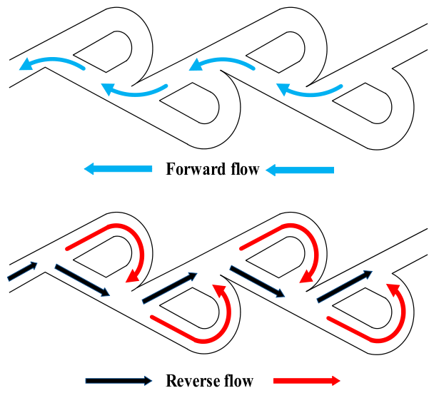
The Tesla valve was originally introduced and named in honor of the Serbian-American scientist Nikola Tesla [17]; it is a passive check valve capable of achieving unidirectional flow conduction, for which an invention patent was filed in 1920. The most distinctive feature of the Tesla valve is that it contains no moving parts and relies solely on its geometric configuration to direct the flow. As a result, it can realize unidirectional flow control without any external energy input. As shown in Figure 1 [18], the flow behaviors in the forward direction (from right to left) and reverse direction (from left to right) differ significantly. Under forward flow conditions, the fluid bypasses all wing-shaped obstacles and passes smoothly from right to left, while being accelerated by the flow pressure. By contrast, during reverse flow, the fluid is repeatedly redirected into the wing-shaped structures—either upward or downward—each time it passes through a channel. This recirculation effect causes flow blockage and increases the pressure head, thereby impeding the overall forward movement of the fluid. Moreover, as the number of wing-shaped obstacles increases, the resistance to fluid transport becomes greater, giving rise to the unique unidirectional flow characteristic of the Tesla valve.
To explore the mechanism responsible for the Tesla valve’s unidirectional flow behavior, numerical simulations were carried out on the valve structure. Water was selected as the working medium, and the internal flow field was assumed to satisfy the continuity equation for incompressible fluids and the differential momentum equations for incompressible viscous flow. A steady-state simulation of the internal flow within the Tesla valve was carried out using the Realizable k–ε turbulence model. The inlet was prescribed as a pressure-inlet boundary with a turbulence intensity of 5%, whereas the outlet was treated as a pressure-outlet boundary with the gauge pressure fixed at 0. The wall boundary was treated as a stationary no-slip wall with standard roughness. In the near-wall region, the CFD model did not directly resolve the flow using extremely fine meshes; instead, non-equilibrium wall functions were adopted to approximate the velocity and pressure distributions, thereby ensuring both computational accuracy and efficiency. The SIMPLEC algorithm was employed for under-relaxed iterative calculations, and the convective terms were discretized using a second-order upwind scheme. To balance computational accuracy with efficiency, a mesh independence study was performed, and the final total number of mesh cells was determined to be 988,344. The turbulence-model calculation in this section is used only for mechanism illustration of the Tesla valve itself and is not directly coupled to the laminar seal-face pressure-field solution presented in the following sections.

2.2. Sealing Principle and Model Establishment

2.2.1. Sealing Principle of the Mechanical Seal

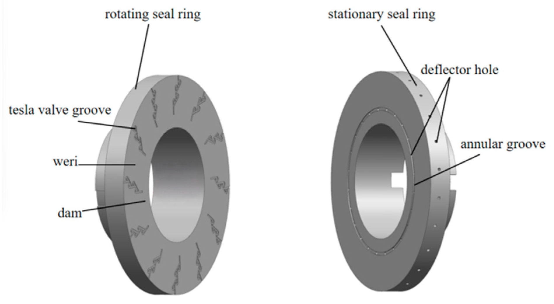
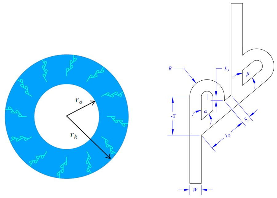
Figure 2 shows the end-face structures of the rotating and stationary rings in the Tesla valve-grooved self-pumping hydrodynamic mechanical seal, and the related geometric parameters are summarized in Table 1. The sealing interface of the rotating ring is composed of a sealing dam and Tesla valve-shaped grooves, whereas the stationary ring is provided with diversion holes and a collecting annular groove. The outer diameter of the stationary ring is adjusted to match that of the rotating ring, and the collecting annular groove is always aligned with the inlet of the Tesla valve-shaped groove. During operation, as the rotating ring rotates, the sealing medium between the rotating and stationary faces flows toward the outlet of the Tesla valve-shaped groove under the combined effects of centrifugal force and inertia. Owing to the unidirectional flow characteristic of the Tesla valve, once the fluid at the groove inlet flows toward the outlet, the pressure at the inlet decreases. Driven by this pressure difference, the fluid in the sealing chamber enters the collecting annular groove through the diversion holes in the stationary ring, then returns to the inlet of the Tesla valve-shaped groove, and is subsequently pumped back into the sealing chamber under the action of centrifugal force, thereby forming a self-pumping circulation.
Figure 3 shows a schematic representation of the four-stage Tesla valve model. Within a single flow-channel unit, L1 denotes primary flow channel length; W is the width of the Tesla valve-type groove; Ht is the depth of the Tesla valve-type groove; ɑ denotes the angle formed by the main channel and the branch channel at the bifurcation location; β denotes the angle between these two channels at the confluence location; L2 refers to the secondary flow channel length; R represents the outer radius of the curved section of the main channel; L3 indicates the confluence section length of the main flow channel; and S is the spacing between two adjacent flow-channel units. Among these parameters, L2, L3, and R are determined by the geometric relationships of the structure, and the corresponding equations are given as follows:
L 2 = W tan α + L 1 W sin α × 1 + tan α 2 tan β 2 + W sin β
R = L 1 W sin α tan α 2 + W
L 3 = L 1 W sin α tan α 2 tan β 2 W tan β

2.2.2. Basic Assumptions

The flow-field analysis of fluid-film-lubricated mechanical seals is inherently complicated. Therefore, in order to simplify the modeling process while still considering the geometric features of the seal ring and the fundamental characteristics of the sealing system, the following assumptions for the fluid film were introduced on the basis of classical fluid mechanics theory, recent research on Tesla valves [19,20] as well as related investigations [21,22,23]:
(1)
The fluid flow between the sealing faces is continuous, and the fluid temperature and viscosity remain constant;
(2)
The fluid film between the sealing faces is considered a Newtonian fluid under laminar flow, where the shear stress is linearly related to the velocity gradient;
(3)
Because the film thickness is very small, the fluid pressure and density are assumed to remain constant along the film-thickness direction;
(4)
No slip is assumed between the fluid and the sealing surfaces;
(5)
The sealing surfaces are assumed to be smooth, and the influence of surface roughness on the fluid flow is disregarded.

2.2.3. Computational Model

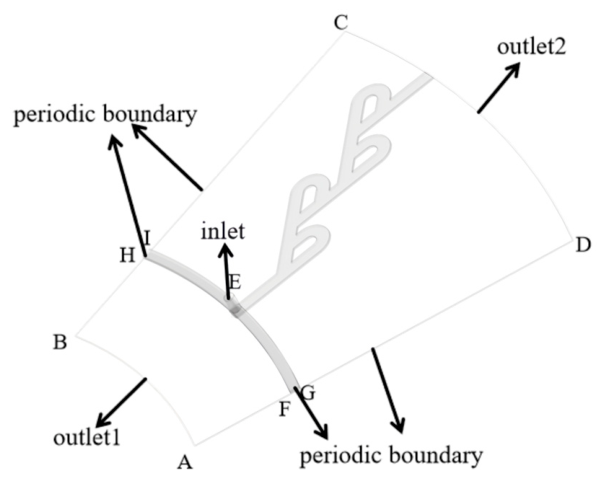
Since the end-face structure of the self-pumping hydrodynamic mechanical seal with Tesla valve-shaped grooves is axisymmetric, the fluid domain formed between the sealing faces can likewise be regarded as symmetric. Therefore, the fluid flow states in the fluid domains occupied by the Tesla valve-shaped grooves on the rotating ring face are identical. To simplify the calculation and reduce the computational cost, the fluid domain corresponding to any one Tesla valve-shaped groove can be selected for analysis [24,25]; that is, only the 1/Ng fluid domain of the sealing face needs to be considered. The computational fluid domain is shown in Figure 4. This model, together with the periodic boundary conditions, is based on an ideal circumferentially uniform assumption. Therefore, the present model is mainly suitable for baseline parametric analysis and optimization, while possible deviations from circumferential periodicity may occur in practical applications.

2.2.4. Governing Equations

For an isothermal and incompressible Newtonian fluid, the flow is governed by the three-dimensional Navier–Stokes equations [26].
ρ u r u r t + u θ r u r θ + u z u r z u θ 2 r = p r + μ 1 r r r u r r + 1 r 2 2 u r θ 2 + 2 u r z 2 u r r 2 2 r 2 u θ θ + f r ρ u r u θ r + u θ r u θ θ + u z u θ z + u r u θ r = 1 r p r + μ 1 r r r u θ r + 1 r 2 2 u θ θ 2 + 2 u θ z 2 u θ r 2 + 2 r 2 u r θ + f θ ρ u r u z r + u θ r u z θ + u z u z z = p z + μ 1 r r r u z r + 1 r 2 2 u z θ 2 + 2 u z z 2 + f z
where r, θ, and z are the coordinate components; ur, uθ, and uz are the velocity components in the r, θ, and z directions, respectively; ρ denotes the density of the sealing fluid, μ represents its dynamic viscosity, fr, fθ, and fz correspond to the body force components along the r, θ, and z directions, respectively, and p indicates the pressure of the sealing medium.
The continuity equation is given by.
1 r r u r r + 1 r u θ θ + u z z = 0
Since the governing equations consist of nonlinear partial differential equations, it is generally challenging to derive analytical solutions. Therefore, numerical simulation is employed in this study to discretize and solve the equations, and the pressure distribution within the fluid film is then obtained.

2.2.5. Boundary Conditions

In the present study, a lubrication-type outlet and boundary treatment were adopted to describe the film-boundary pressure behavior, while the pressure field in the seal domain was solved directly from the three-dimensional Navier–Stokes equations [27,28]. The specific boundary conditions are summarized in Table 2.

2.2.6. Mesh Generation and Solver Settings

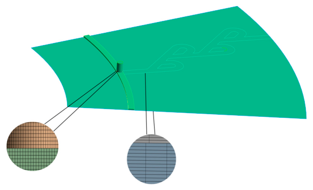
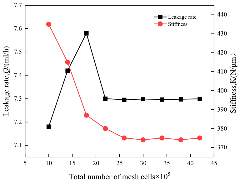
The non-equilibrium wall-function treatment is used only in the standalone Tesla-valve flow analysis in Section 2.1 for mechanism illustration. The subsequent seal-performance simulation is based on a steady laminar-flow model with explicit layered meshing in the film-thickness direction. Therefore, the main micrometer-scale seal-film results are not obtained from a wall-function-based near-wall approximation. Because the film thickness is on the micrometer scale and differs from the other model dimensions by several orders of magnitude, different meshing strategies were adopted for different regions in order to satisfy the mesh-resolution requirement for parameter calculation in the film-thickness direction. In this study, the computational model was first created in SolidWorks 2022 and then transferred to ANSYS Meshing 2025 for grid generation, as shown in Figure 5. The model was divided into four subdomains—namely the diversion hole, the collecting annular groove, the fluid film, and the Tesla valve-type groove—with each region being meshed separately. The source and target faces were specified using the Src/Trg option, and the number of layers was controlled by the Num Div parameter. Grid independence was evaluated using the leakage rate and film stiffness as the performance indicators, based on which the final total number of mesh cells was determined. As shown in Figure 6, when the total number of mesh cells reached approximately 2.4 million, the calculated results became stable. Therefore, this mesh density was adopted to achieve a balance between computational accuracy and efficiency.
Because the governing equations are nonlinear partial differential equations, obtaining exact analytical solutions is generally difficult. Therefore, Fluent was employed for numerical computation [29]. The numerical analysis was performed with a three-dimensional, double-precision solver under steady laminar flow conditions. The pressure–velocity coupling was treated using the SIMPLEC scheme, and both diffusion and convection terms were discretized with a second-order upwind method. The convergence tolerance was specified as 10−6.

2.3. Multi-Objective Optimization Based on the NSGA-II Genetic Algorithm

2.3.1. Uniform Experimental Design

The detailed procedure for the uniform experimental design is as follows:
(1) Determination of the experimental objectives and influencing factors. To ensure the stable operation of the seal, leakage rate and fluid-film stiffness were selected as the optimization objectives. In accordance with the requirements of structural optimization, the effects of diversion angle and valve clearance on sealing performance were first examined through the single-factor analysis of structural parameters. To further identify the optimal groove configuration, groove depth and groove width were also incorporated into the uniform experimental design as design variables. Consequently, four structural parameters, namely Tesla valve groove depth, diversion angle, valve clearance, and Tesla valve groove width, were selected as the experimental factors.
(2) Determination of factor ranges and levels. According to the experimental objectives and prior research experience, a uniform design with four factors and 17 levels was established. Combined with the uniform design table, the range of each experimental factor was determined. The value ranges of the structural parameters are presented in Table 3, and the corresponding levels were defined within these ranges.

2.3.2. Multi-Objective Optimization

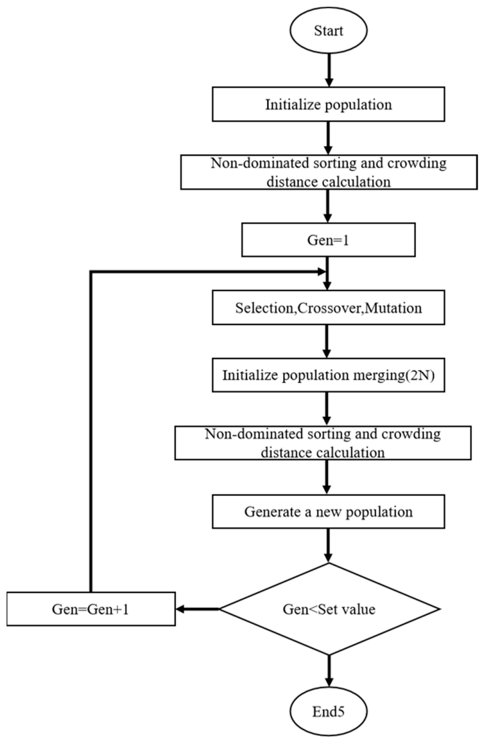
In traditional multi-objective optimization, methods such as the weighted-sum method, integer programming, and linear programming are widely used. These methods share a common feature in that they convert a multi-objective optimization problem into a single-objective problem, which is then solved using single-objective optimization techniques. While a unique optimal solution can generally be identified in single-objective optimization, no unique global optimum exists in multi-objective optimization. Instead, a set of solutions is typically obtained, and these solutions cannot be directly compared in a simple manner. Such a set is referred to as the non-dominated solution set, or the Pareto-optimal solution set. As one of the most widely used multi-objective genetic algorithms, NSGA-II incorporates non-dominated sorting, crowding distance, a crowding comparison operator, and an elitist strategy, thereby offering the advantages of high computational efficiency and good convergence performance.
For the Tesla valve-shaped face-groove self-pumping mechanical seal, the multi-objective optimization problem essentially aims to increase the fluid-film stiffness while reducing the leakage rate under given operating conditions. For the convenience of unified solution using the NSGA-II algorithm, the objective of maximizing the fluid-film stiffness is equivalently transformed into the minimization of −K. Accordingly, the mathematical model of the optimization problem can be expressed as follows:
V min f ( X ) = [ Q ( X ) , K ( X ) ] T
Decision variables:
X = α , S , H t , W
Constraints: α ∈ [50, 75], S ∈ [0.1, 0.6], Ht ∈ [10, 60], W ∈ [0.3, 0.55].
The detailed procedure of the NSGA-II algorithm is illustrated in Figure 7.
The initial population size was set to 200, and the mutation probability was set to 0.9. After 300 generations of iteration, the optimal Pareto front was obtained.

2.3.3. Necessity of Multicriteria Decision-Making and TOPSIS Procedure

In the present study, the optimization of the Tesla valve-shaped face-groove self-pumping mechanical seal involves two objectives, namely, minimizing the leakage rate and maximizing the fluid-film stiffness. These two objectives are inherently conflicting to some extent because structural parameter combinations that are favorable for reducing leakage do not necessarily lead to the highest fluid-film stiffness, and vice versa. Therefore, no single solution can be simultaneously optimal for all objectives. Instead, the optimization process yields a set of non-dominated solutions, namely, the Pareto-optimal solution set, in which improvement in one objective is achieved at the expense of deterioration in another. Consequently, a multicriteria decision-making method is required to identify the most suitable compromise solution from the Pareto front. In this study, the TOPSIS method was adopted for this purpose because it enables the candidate solutions to be ranked according to their relative closeness to the ideal best solution and remoteness from the ideal worst solution under specified weighting coefficients.

3. Results

3.1. Analysis of the Flow Characteristics of the Tesla Valve

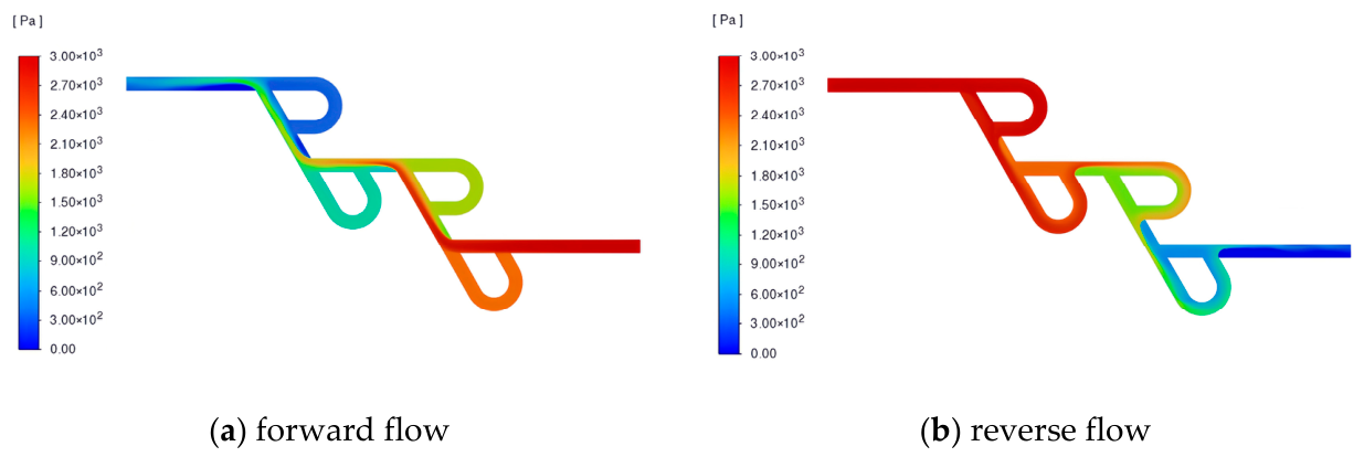
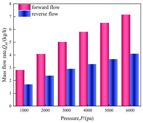
The simulation results are shown in Figure 8. Under the forward-flow condition [Figure 8a], the fluid flows primarily along the main channel. In contrast, under the reverse-flow condition [Figure 8b], the fluid is diverted into the branch channel at the bifurcation point, which makes it more difficult for the fluid to exit the valve. A comparison between the two flow conditions shows that, under the same pressure-driving condition, the pressure in the reverse-flow case is lower than that in the forward-flow case. To further evaluate the flow characteristics of the Tesla valve, the inlet pressure was varied and the outlet flow rates under forward and reverse flow conditions were compared at different pressure differences. As illustrated in Figure 9, as the inlet pressure increases, the outlet flow rate under reverse-flow conditions remains consistently lower than that observed in the forward-flow case, which clearly reflects the unidirectional flow capability of the Tesla valve.

3.2. Effects of Structural Parameters on Sealing Performance

3.2.1. Comparison of Sealing Performance

For comparison, the seal-ring structural parameters of the Tesla valve self-pumping hydrodynamic mechanical seal were set identically to those of the diffuser-type self-pumping hydrodynamic–hydrostatic mechanical seal, as listed in Table 1. The difference between the two structures lies mainly in the groove configuration, with the Tesla valve design eliminating the diffuser annular groove. In this study, all calculations were performed under the operating conditions of a rotational speed of 8000 r/min and a sealing-medium pressure of 0.5 MPa. Based on these conditions, a comparative analysis was conducted on the sealing performances of the diffuser-type self-pumping hydrodynamic–hydrostatic mechanical seal and the self-pumping hydrodynamic mechanical seal with Tesla valve-shaped grooves.
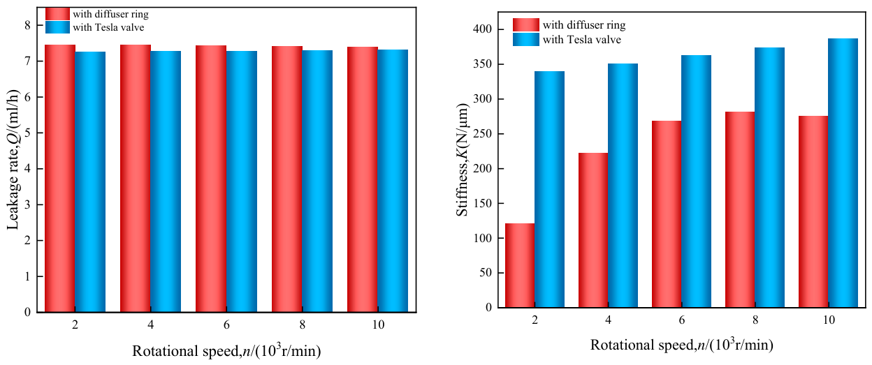
To assess the behavior of the two mechanical seals at different rotational speeds, a variable-speed analysis was performed. As shown in Figure 10, the diffuser-type self-pumping hydrodynamic mechanical seal exhibits a gradual reduction in leakage rate with increasing rotational speed. In contrast, the Tesla valve-grooved self-pumping hydrodynamic mechanical seal shows the opposite tendency, with leakage increasing as the speed rises. In general, within the rotational-speed range of 2000–10,000 r/min, the Tesla valve-type groove design demonstrates a lower leakage rate compared with the diffuser-type structure. However, when the rotational speed exceeds 10,000 r/min, its leakage rate tends to become higher than that of the diffuser-type structure. This phenomenon can be attributed to the rectifying (one-way flow) property of the Tesla valve. At low to intermediate rotational speeds, the fluid is more likely to accumulate in the branch channels, which results in a reduced pressure difference across the sealing dam relative to the diffuser-type design, and therefore a lower leakage rate. Under high-speed operating conditions, however, the centrifugal force is significantly enhanced, weakening the driving effect of the pressure difference. At the same time, pronounced secondary flows develop inside the Tesla valve-shaped grooves, leading to the formation of localized low-pressure vortex cores and a gradual increase in leakage rate. Regarding stiffness performance, the Tesla valve-type groove structure maintains a higher fluid-film stiffness than the diffuser-type design across the entire operating range, and its stiffness increases further as the rotational speed rises. The difference in stiffness between the two structures becomes minimal within the speed range of 6000–8000 r/min. Because the Tesla valve structure features multiple local high-pressure regions and does not include a diffuser annular groove, its effective sealing area is relatively smaller, leading to a greater contribution from the hydrodynamic effect and thus superior overall stiffness performance. In summary, the present results suggest that the proposed Tesla-valve-type seal is more suitable for non-ultrahigh-speed operating conditions. Under the current simulated geometry and operating conditions, the structure shows a favorable performance window in the range of 2000–10,000 r/min, within which the leakage rate remains lower than that of the diffuser-type seal while the fluid-film stiffness is consistently higher. When the rotational speed exceeds 10,000 r/min, however, the leakage advantage is lost, and the proposed structure may no longer be the preferred choice for applications in which leakage control is the dominant requirement.

3.2.2. Effect of Diversion Angle on Sealing Performance

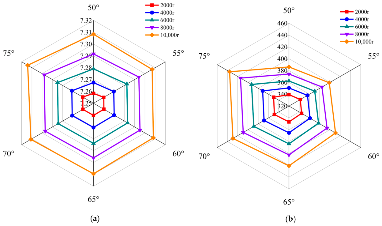
Figure 11 presents the effects of the diversion angle of the Tesla valve-type groove on both leakage rate and fluid-film stiffness under different rotational speeds. It can be observed that the leakage rate remains nearly unchanged with increasing diversion angle under all rotational-speed conditions. This can mainly be attributed to the fact that, within the examined angular range, changes in the diversion angle have little influence on the strong resistance of the Tesla valve to reverse flow. As a result, the positions of the multiple high-pressure zones remain nearly constant, and the pressure difference across the sealing dam varies only slightly, leading to minimal changes in leakage rate. By contrast, the fluid-film stiffness rises with an increase in the diversion angle, and this effect becomes increasingly evident at higher rotational speeds. This can be attributed to the fact that a larger diversion angle enhances the unidirectional flow characteristic of the Tesla valve, making fluid discharge under reverse-flow conditions more difficult. As a consequence, more fluid is retained within the flow channel, leading to greater pressure build-up and a stronger hydrodynamic effect. Meanwhile, the self-pumping circulation process driven by the pressure difference becomes more effective, which further improves the uniformity of the fluid-film pressure distribution and ultimately enhances the fluid-film stiffness.
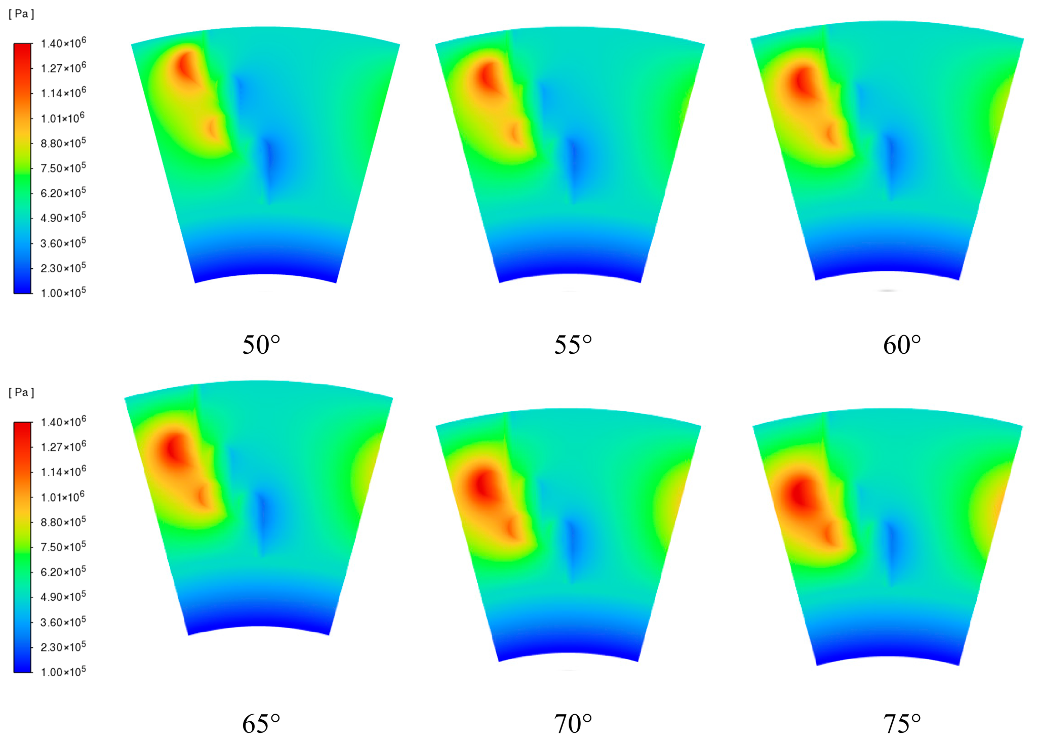
Figure 12 shows the pressure contours of the sealing face at different diversion angles with the inner and outer diameters of the rotating ring kept constant. As the diversion angle increases, the high-pressure region gradually expands and reaches its largest area at a diversion angle of 75°. This indicates that the hydrodynamic effect becomes progressively stronger with increasing diversion angle, which in turn enhances the fluid-film stiffness.

3.2.3. Effect of Valve Clearance on Sealing Performance

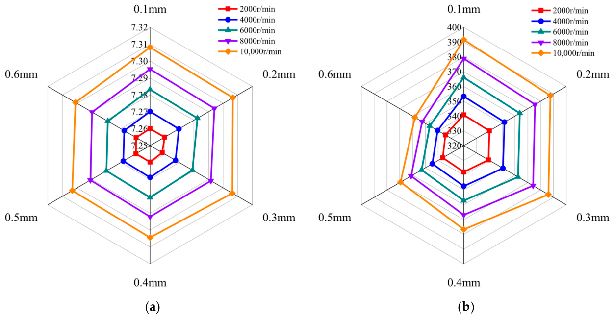
Figure 13 shows how the valve clearance of the Tesla valve-type groove affects the leakage rate and fluid-film stiffness at different rotational speeds. It can be seen that, under all investigated speed conditions, the leakage rate changes only slightly as the valve clearance increases, although its overall magnitude increases with rotational speed. This is primarily because changes in valve clearance have a limited effect on the pressure difference across the sealing dam, and therefore do not cause an obvious variation in leakage rate. By contrast, the fluid-film stiffness gradually declines as the valve clearance increases, and this decreasing trend becomes more pronounced at higher rotational speeds. This can be attributed to the fact that a larger valve clearance prolongs the time required for the fluid to reach the next-stage structure, thereby weakening the unidirectional flow characteristic of the Tesla valve and reducing the hydrodynamic effect. At the same time, the effectiveness of the self-pumping circulation diminishes, leading to a less uniform pressure distribution in the fluid film and, consequently, a reduction in fluid-film stiffness.
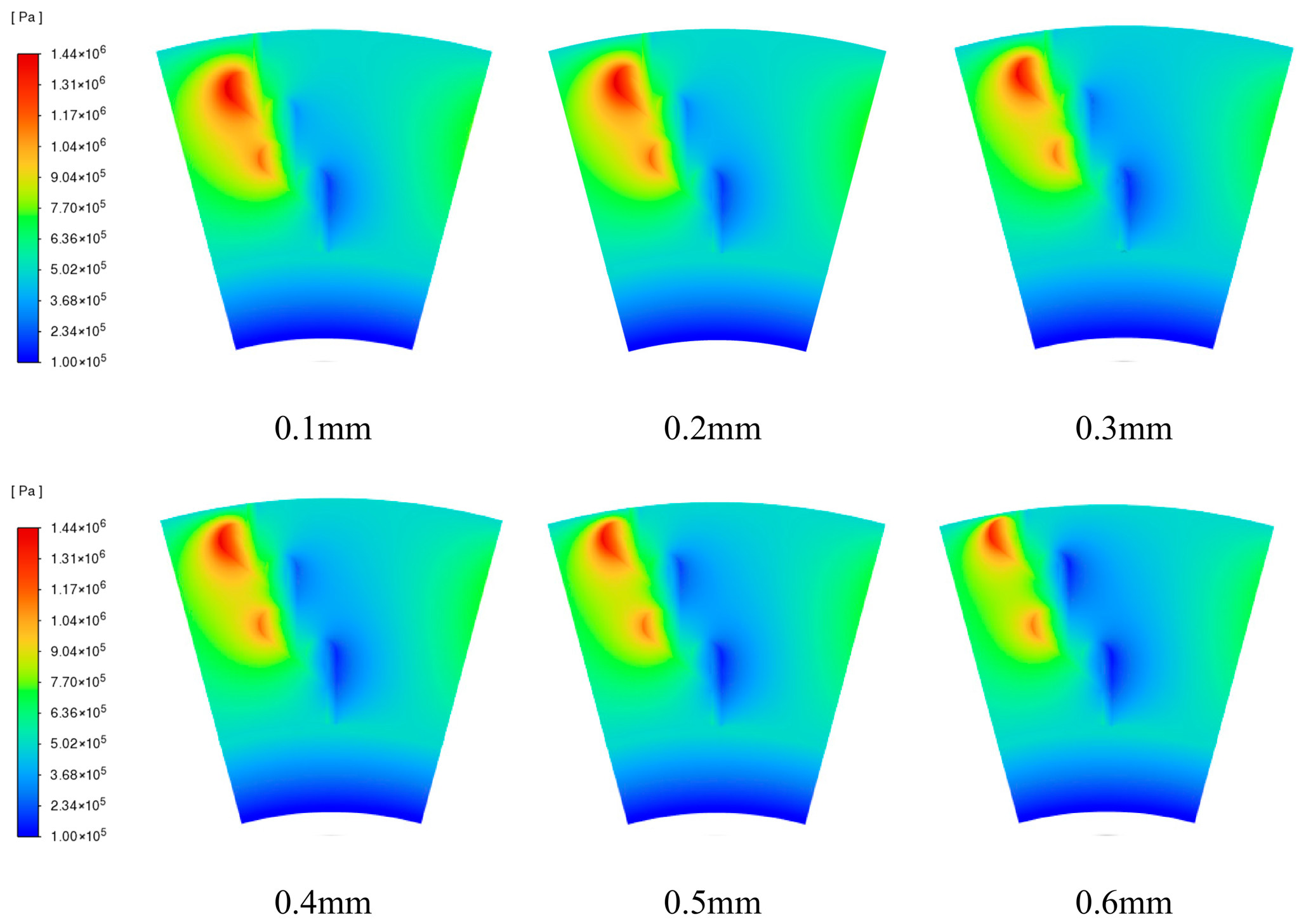
Figure 14 shows the pressure contours of the sealing face at different valve clearances with the inner and outer diameters of the rotating ring kept constant. As the valve clearance increases, the high-pressure region gradually shrinks, indicating that the hydrodynamic effect is continuously weakened. When S = 0.3 mm, the hydrodynamic effect decreases sharply, which in turn results in a significant reduction in fluid-film stiffness.

3.3. Optimization Analysis

3.3.1. Construction of Regression Equations

To construct the regression models for the two optimization objectives, namely leakage rate and fluid-film stiffness, the uniform experimental design results are summarized in Table 4. In this table, x1, x2, x3, and x4 represent the Tesla-valve groove depth, divergence angle, valve clearance, and Tesla-valve groove width, respectively, while K and Q denote the fluid-film stiffness and leakage rate. The data listed in Table 4 were subsequently used for regression analysis and optimization modeling.
Taking the leakage rate Q in Table 4 as the objective function, a quadratic polynomial was fitted to the data, and the resulting predictive model for the leakage rate can be expressed as follows:
Q = 7.87257303 + 0.0011626688150 x 1 + 9.515 x 2 0.122 x 3 +   0.00026 x 1 2 + 8.947 x 2 2 + 0.159 x 3 2 0.00153 x 4 2   0.175 x 1 x 2 + 0.031 x 1 x 3 + 0.001 x 1 x 4 1.968 x 2 x 3 +   0.0443 x 2 x 4 0.00082 x 3 x 4
The remaining terms were excluded because their significance with respect to the dependent variable was extremely low. The regression equation was then statistically validated. The multiple correlation coefficient was R = 0.9734, indicating a strong correlation between the leakage rate and the structural parameters retained in the equation. The significance level was p = 0.0118 < 0.05, confirming that the regression model is statistically significant. Furthermore, the sum of squared errors was SSE = 0.0157, and the adjusted correlation coefficient was Ra = 0.97, indicating that the regression equation has high credibility.
Similarly, the predictive model for fluid-film stiffness K can be expressed as follows:
K = 69.9002642 2.1770810095 x 1 + 4.986149852 x 2   57.29939951 x 3 + 1482.4002251 x 4 +   0.935 x 1 2 + 8308.58 x 2 2 + 58.490 x 3 2 + 0.367 x 4 2   25.387 x 1 x 2 + 11.888 x 1 x 3 + 0.0763 x 1 x 4 +   96.164 x 2 x 3 + 61.949 x 2 x 4 + 5.760 x 3 x 4
The regression equation was then statistically validated. The multiple correlation coefficient was R = 0.9922, indicating a strong correlation between the fluid-film stiffness and the structural parameters retained in the equation. The significance level was p = 0.0285 < 0.05, confirming that the regression model is statistically significant. Furthermore, the sum of squared errors was SSE = 0.0041, and the adjusted coefficient was Ra = 0.9853, indicating that the regression equation has very high credibility.

3.3.2. Obtaining the Pareto-Optimal Solution Set

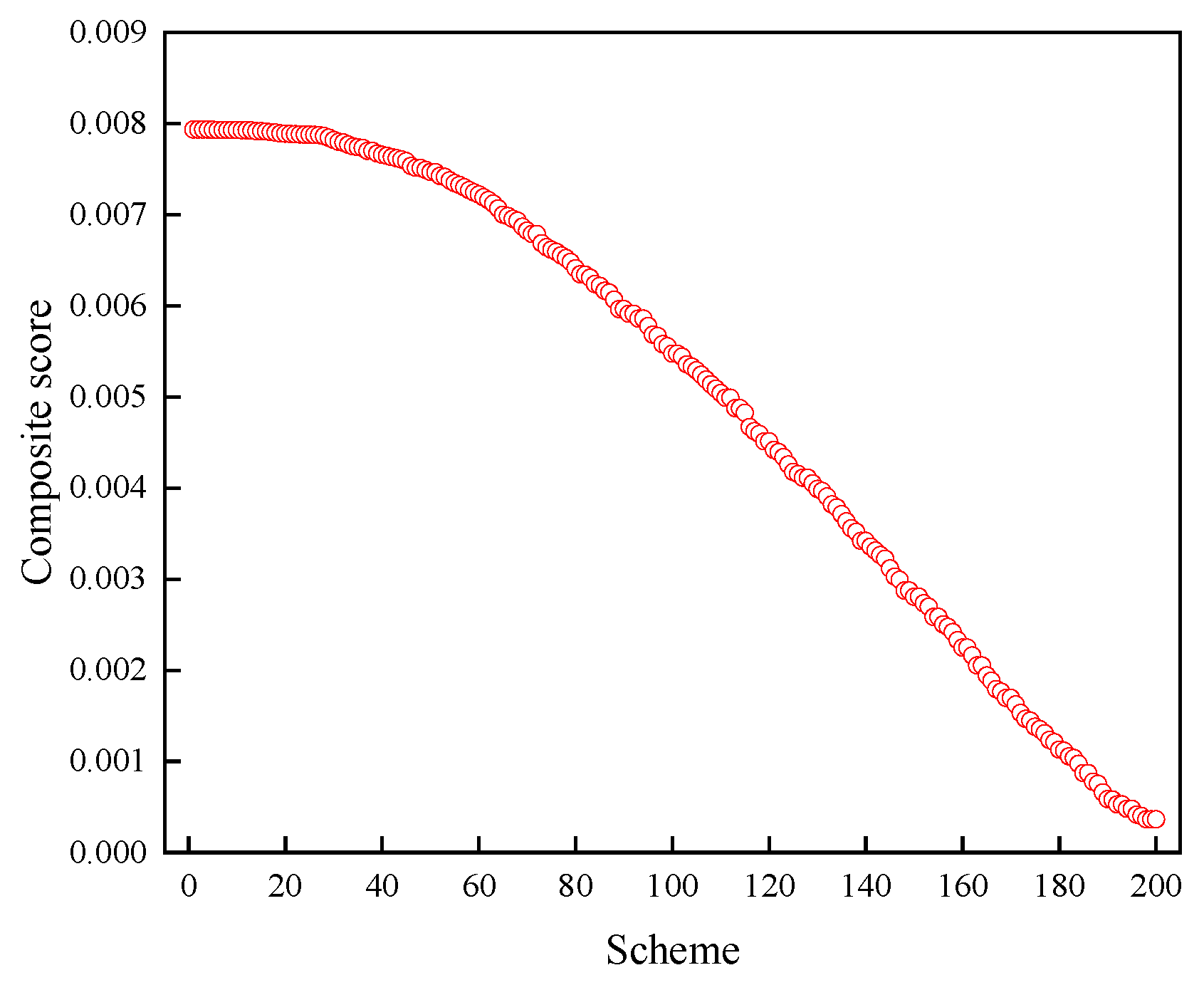
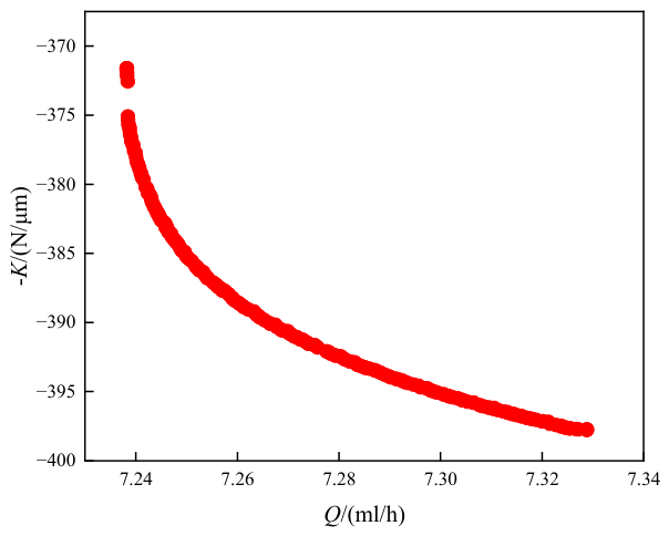
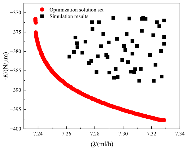
As shown in Figure 15, the Pareto-optimal solution set forms a smooth front, exhibiting good uniformity and dispersion.
Under the conditions of an outer diameter of 50.5 mm, an inner diameter of 26.5 mm, 12 grooves, a Tesla valve main-channel length of 1.7 mm, a branch-channel length of 0.8 mm, and an arc radius of 0.6 mm, different structural configurations were randomly selected for numerical simulation within the following parameter ranges: Tesla valve groove depth of 10–60 μm, diversion angle of 50–75°, valve clearance of 0.1–0.6 mm, and Tesla valve groove width of 0.3–0.55 mm. The sealing performance data were recorded and then compared with the optimized results obtained using the NSGA-II algorithm, as shown in Figure 16. The optimized structure exhibits a distinctly reduced leakage rate and a significantly improved fluid-film stiffness, which verifies the reliability of the proposed optimization design method for enhancing the performance of the Tesla valve-shaped face-groove self-pumping hydrodynamic mechanical seal.

3.3.3. Decision Analysis Based on the TOPSIS Method

(1) Positive transformation of the indices. The evaluation indices of the alternatives can be divided into four categories: benefit-type, cost-type, intermediate-type, and interval-type indices. To ensure consistency in index orientation, all indices must be subjected to positive transformation, meaning that they are all converted into benefit-type indices through data processing. In this study, leakage rate is a cost-type index, for which a smaller value is preferable, whereas fluid-film stiffness is a benefit-type index, for which a larger value is desirable. Therefore, the leakage rate should be transformed into a benefit-type index, and the transformed leakage-rate index is defined as follows:
Q i * = Q max Q i Q max Q min
Since fluid-film stiffness is a benefit-type index, its positively transformed form is given by
K i * = K i K min K max K min
(2) Construction of the evaluation matrix. For the i-th candidate solution, its evaluation vector can be expressed as
x i = Q i * , K i *
Subsequently, the evaluation matrix for all candidate solutions is obtained as:
X = Q 1 * K 1 * Q 2 * K 2 * Q n * K n *
(3) Weight assignment. Considering the combined requirements of low leakage rate and high fluid-film stiffness in this study, the weights of the two objectives are defined as ωQ and ωK, respectively, and satisfy
ωQ + ωK = 1
Accordingly, the weighted evaluation vector of the i-th candidate solution is given by
z i = ω Q Q i * , ω K K i *
(4) Determination of the ideal best and ideal worst solutions. Since all indices become benefit-type indices after positive transformation and weighting, the ideal best solution is defined as
z + = max ω Q Q i * , max ω K K i *
Similarly, by extracting the minimum value from each column, the ideal worst solution vector can be constructed as
z = min ω Q Q i * , min ω K K i *
(5) Calculation of the distances from each solution to the ideal solutions. The Euclidean distances from the i-th solution to the ideal best solution and the ideal worst solution are expressed, respectively, as
D i + = ω Q Q i * z Q + 2 + ω K K i * z K + 2 D i = ω Q Q i * z Q 2 + ω K K i * z K 2
(6) Calculation and ranking of the closeness coefficient. The comprehensive evaluation value of the i-th solution is defined as
C i = D i D i + D i +
where 0 ≤ Ci ≤ 1. The larger the value of Ci, the closer the corresponding solution is to the ideal best solution and the farther it is from the ideal worst solution; therefore, the better its overall performance.
In multi-objective optimization, no solution exists that can simultaneously optimize every objective. Therefore, each solution on the Pareto front is regarded as equally acceptable for the multi-objective optimization problem. Since the two objectives are influenced by their assigned weights, the TOPSIS method was used to rank the solutions in the Pareto-optimal set, and the structural parameter combination with the highest score was selected as the optimal design. In this study, leakage rate and fluid-film stiffness were regarded as equally important performance indices because the former reflects sealing effectiveness, whereas the latter reflects the load-carrying stability of the fluid film. Since the aim of the present work was to identify a balanced structural design without imposing an application-specific preference on either objective, equal weights of 0.5 and 0.5 were assigned in the TOPSIS analysis as a neutral decision basis. Under this weighting condition, the top-ranked solution was identified as the optimal compromise structure. The TOPSIS scores of the Pareto-optimal solution set are shown in Figure 17. Accordingly, the optimal structural parameters were determined to be a Tesla valve groove depth of 10.02 μm, a diversion angle of 50.2°, a valve clearance of 0.12 mm, and a Tesla valve groove width of 0.45 mm. However, the groove depth of 10.02 μm is only the theoretical optimum; therefore, an approximate value of 10 μm was adopted in actual machining. The influence of machining tolerance on sealing performance will be further evaluated in subsequent experiments to ensure the engineering feasibility of the theoretical design.

4. Conclusions

In this study, a self-pumping hydrodynamic mechanical seal with Tesla valve-shaped face grooves was proposed, and a numerical fluid-domain model was established to investigate its sealing mechanism and structural performance. The results showed that the proposed structure can generate a self-pumping circulation through the Tesla valve-shaped grooves, diversion holes, and collecting annular groove. Due to the high resistance of the Tesla valve to reverse flow, multiple local high-pressure regions are formed on the sealing face, thereby enhancing the hydrodynamic effect and improving the fluid-film stiffness.
With respect to the effects of structural parameters, the leakage rate was found to be relatively insensitive to both the diversion angle and valve clearance within the investigated ranges, whereas the fluid-film stiffness increased with increasing diversion angle and decreased with increasing valve clearance. Based on the regression models, NSGA-II optimization, and TOPSIS decision-making, an optimal parameter combination was obtained. To obtain a balanced compromise between low leakage rate and high fluid-film stiffness under a general design objective, equal weights of 0.5 were assigned to the two optimization objectives in the TOPSIS decision-making process. Under this weighting condition, the optimal parameter combination was determined to be a groove depth of 10.02 μm, a diversion angle of 50.2°, a valve clearance of 0.12 mm, and a groove width of 0.45 mm. These results provide useful theoretical guidance for the structural design of self-pumping mechanical seals.
From the perspective of surface engineering, the present work also provides theoretical support for the design of functional textured or coated interfaces with improved tribological performance. The proposed structural optimization strategy may also be of potential interest for advanced materials and coatings used in high-speed sealing and lubrication-related applications.
Nevertheless, some limitations of the present study should be noted. The current work is mainly based on numerical simulation and optimization, and the proposed design has not yet been validated through systematic experiments. In addition, the model was developed under several simplifying assumptions, including isothermal, incompressible, Newtonian, and laminar flow, as well as smooth sealing faces, which may restrict its applicability under more complex practical conditions. Moreover, the optimization results were obtained under prescribed operating conditions and a specific weighting strategy; therefore, their direct applicability to other operating scenarios should be evaluated with caution.
Future work will focus on the experimental validation of the proposed seal structure, as well as on the effects of machining tolerance and assembly deviation on sealing performance. Although the Tesla-valve-type groove is geometrically more complex than conventional spiral or diffuser grooves, it remains a face-based micro-groove texture and is therefore considered manufacturable in principle using existing micro-texturing techniques. Such machining deviations may modify the rectification effect of the Tesla-type channel, the local pressure build-up, and the self-pumping circulation efficiency, thereby affecting the leakage rate and fluid-film stiffness. Therefore, the influence of machining tolerance and profile deviation should be further investigated experimentally and through robustness analysis in future work. Further studies should also consider thermo-hydrodynamic behavior, transient operating conditions, possible fluid– structure interaction effects and incorporate rough-surface or mixed-lubrication modeling in order to improve the engineering reliability of the model. In addition, the sensitivity of the optimal solutions to different weighting coefficients and practical design priorities should be further investigated for specific engineering applications.

Author Contributions

Data curation, Y.J., J.S., J.Z. and T.H.; formal analysis, Y.J.; validation, Y.J.; writing—review and editing, Y.J. and J.S. All authors have read and agreed to the published version of the manuscript.

Funding

This work was supported by the Guizhou Provincial Key Laboratory of Mountainous Intelligent Agricultural Machinery (Qiankehe Platform ZSYS [2025]013), the National Natural Science Foundation of China (Grant No. 52505064), the National Key Laboratory of Science and Technology on Advanced Light-duty Gas-turbine (GZJJ-KF-2025-01), the Research and Practice Innovation Program for Graduate Students in Jiangsu Province (Grant No. KYCX25_1399), and the open project of Key Laboratory of Agricultural Equipment Technology for Hilly and Mountainous Areas, Ministry of Agriculture and Rural Affairs (No. 2025QSNZ05) and the Yancheng Key Research and Development Plan (Industrial) Project (grant number BE2023023).

Institutional Review Board Statement

Not applicable.

Informed Consent Statement

Not applicable.

Data Availability Statement

Data are contained within the article.

Conflicts of Interest

The authors declare no conflicts of interest.

References

  1. Jiang, H.; Yu, S.; Wang, S.; Ding, X.; Jiang, A. Research Status and Development Trend of Cylindrical Gas Film Seals for Aeroengines. Processes 2023, 12, 69. [Google Scholar] [CrossRef] [Scilit]
  2. Mathew, M.D. Nuclear Energy: A Pathway towards Mitigation of Global Warming. Prog. Nucl. Energy 2022, 143, 104080. [Google Scholar] [CrossRef] [Scilit]
  3. Xu, L.; Wu, J.H.; Yuan, X.; Hao, M.; Liu, F.; Liu, Y.; Xie, X. Influence of Inlet Pressure Disturbance on Transient Performance of Liquid Oxygen Lubricated Mechanical Seal and Rub-Impact Phenomenon Caused by Excitation Overload. Tribol. Int. 2023, 178, 108058. [Google Scholar] [CrossRef] [Scilit]
  4. Faria, M.T.C.; Mendes Miranda, W. Pressure Dam Influence on the Performance of Gas Face Seals. Tribol. Int. 2012, 47, 134–141. [Google Scholar] [CrossRef] [Scilit]
  5. Liu, Y.; Ren, J.L.; Cao, H. Reform of Mechanical Shaft Sealing Self-Flush System of Petrochemical Hot Oil Centrifugal Pump. Appl. Mech. Mater. 2013, 331, 106–109. [Google Scholar] [CrossRef] [Scilit]
  6. Qiu, Y.; Khonsari, M.M. Thermohydrodynamic Analysis of Spiral Groove Mechanical Face Seal for Liquid Applications. J. Tribol. 2012, 134, 021703. [Google Scholar] [CrossRef] [Scilit]
  7. Cheng, G.; Guo, F.; Zang, X.; Zhang, Z.; Jia, X.; Yan, X. Failure Analysis and Improvement Measures of Airplane Actuator Seals. Eng. Fail. Anal. 2022, 133, 105949. [Google Scholar] [CrossRef] [Scilit]
  8. Sun, J.; Min, W.; Min, Z. Self-Pumping Hydrodynamic Mechanical Seals. CN103267132A, 28 August 2013. [Google Scholar]
  9. Lu, J.; Sun, J.; Chen, W.; Ma, C.; Yan, Y. Performance comparison between self-pumping mechanical seals and spiral-groove mechanical seals. CIESC J. 2016, 67, 8. [Google Scholar]
  10. Ge, C.; Sun, J.; Su, X.; Yu, Q. Performance analysis on diffuser self-pumping hydrodynamic and hydrostatic mechanical seal. CIESC J. 2020, 71, 13. [Google Scholar]
  11. Zhang, G.; Chen, G.; Zhao, W.; Yan, X.; Zhang, Y. An Experimental Test on a Cryogenic High-Speed Hydrodynamic Non-Contact Mechanical Seal. Tribol. Lett. 2017, 65, 80. [Google Scholar] [CrossRef] [Scilit]
  12. Wang, J.; Men, C.; Zhao, W.; Jia, Q.; Cui, Y.; Zhang, C.; Yuan, X. Research on Structural Design and End Face Slot of Optimization of Hydrodynamic and Hydrostatic Mechanical Seal. J. Mech. Eng. 2021, 57, 108. [Google Scholar]
  13. Wang, X.; Shi, L.; Huang, W.; Wang, X. A Multi-Objective Optimization Approach on Spiral Grooves for Gas Mechanical Seals. J. Tribol. 2018, 140, 041701. [Google Scholar] [CrossRef] [Scilit]
  14. Rao, Y.; Sun, J.; Wen, L. Research on Liquid Film Vaporization and Structural Optimization of End Faces for Diffuser Self-pumping Mechanical Seals. China Mech. Eng. 2025, 36, 933–941+953. [Google Scholar]
  15. Moory Shirbani, M.; Alavi, S. Multi-objective optimization and performance analysis of bimorph magneto-electro-elastic energy harvesters. Facta Univ. Ser. Mech. Eng. 2025, 23, 667–686. [Google Scholar] [CrossRef] [Scilit]
  16. Stefanović-Marinović, J.; Perić, M.; Miltenović, A.; Marinković, A.; Ćojbašić, Ž. An Approach to Multicriteria Optimization of the Three-Stage Planetary Gear Train. Machines 2025, 13, 978. [Google Scholar] [CrossRef] [Scilit]
  17. Tesla, N. Valvular Conduit. U.S. Patent 1329559, 3 February 1920. [Google Scholar]
  18. Varnier, F.; Norouzikudiani, R.; Corsi, G.; Agostinelli, D.; Levin, I.; DeSimone, A. Hydraulic Asymmetries for Biological and Bioinspired Valves in Tubular Channels: A Numerical Analysis. Biomimetics 2026, 11, 87. [Google Scholar] [CrossRef] [Scilit]
  19. Weng, X.; Yan, S.; Zhang, Y. Design, simulation and experimental study of a micromixer based on Tesla valve structure. Chem. Ind. Eng. Prog. 2021, 40, 4173–4178. [Google Scholar]
  20. Monika, K.; Chakraborty, C.; Roy, S. A numerical analysis on multi-stage Tesla valve based cold plate for cooling of pouch type Li-ion batteries. Int. J. Heat Mass Transf. 2021, 177, 121560. [Google Scholar] [CrossRef] [Scilit]
  21. Gani, M.; Santos, I.F.; Arghir, M.; Grann, H. Model Validation of Mechanical Face Seals in Two-Phase Flow Conditions. Tribol. Int. 2022, 167, 107417. [Google Scholar] [CrossRef] [Scilit]
  22. Li, X.; Shao, H.; Li, Z.; Hao, M.; Wang, Z. Study on the Thermal Phase Change Characteristics and Its Evolution Law of Liquid Oxygen Mechanical Seals. Appl. Therm. Eng. 2026, 286, 129320. [Google Scholar] [CrossRef] [Scilit]
  23. Ben-Abdelwahed, A.; Liu, S.; Sommier, A.; Reungoat, D. Experimental and Numerical Analysis of Heat Transfer and Thermal Deformation in Small-Dimension Liquid Mechanical Seals. Int. J. Heat Mass Transf. 2025, 241, 126754. [Google Scholar] [CrossRef] [Scilit]
  24. Wang, Q.; Chen, H.L.; Liu, T. Research on performance of upstream pumping mechanical seal with different deep spiral groove. IOP Conf. Ser. Earth Environ. Sci. 2012, 15, 072019. [Google Scholar] [CrossRef] [Scilit]
  25. Hu, Q.; Wang, J.; Zhu, L.; Chen, Y.; Wang, Y.; Sun, Y.; Wang, X. Numerical and Experimental Investigations into Characteristics of Liquid Film Seals Featuring Various Groove Shapes Based on Super-Slip Groove Design. Tribol. Int. 2024, 199, 109978. [Google Scholar] [CrossRef] [Scilit]
  26. Ma, C. Study on the Lubrication Computational Model and Antifriction Performance of Textured Surfaces. Ph.D. Thesis, China University of Mining and Technology, Xuzhou, China, 2010. [Google Scholar]
  27. Xu, W.; Tian, Y.; Li, K.; Zhang, M.; Yang, J. Reynolds Boundary Condition Realization in Journal Bearings: Location of Oil Film Rupture Boundary with Layering-Sliding Mesh Method. Tribol. Int. 2022, 165, 107330. [Google Scholar] [CrossRef] [Scilit]
  28. Kamat, H.; Kini, C.R.; Shenoy, S.B. Effect of Cavitation and Temperature on Fluid Film Bearing Using CFD and FSI Technique: A Review. Arch. Comput. Methods Eng. 2022, 30, 1623–1636. [Google Scholar] [CrossRef] [Scilit]
  29. Zhang, J.; Chen, Q.; Shi, M.; Zhou, H.; Xu, L. Interaction and Influence of a Flow Field and Particleboard Particles in an Airflow Forming Machine with a Coupled Euler-DPM Model. PLoS ONE 2021, 16, e0253311. [Google Scholar] [CrossRef] [Scilit]
Figure 1. Schematic diagram of the Tesla valve [18].
Coatings 16 00565 g001
Figure 2. Configuration of rotating and stationary rings in the mechanical seal.
Coatings 16 00565 g002
Figure 3. Structural parameters of the groove on the rotating ring end face.
Coatings 16 00565 g003
Figure 4. Computational fluid domain.
Coatings 16 00565 g004
Figure 5. Generated mesh of the computational subdomains.
Coatings 16 00565 g005
Figure 6. Grid independence verification.
Coatings 16 00565 g006
Figure 7. NSGA-II algorithm flowchart.
Coatings 16 00565 g007
Figure 8. Schematic diagram of forward and reverse flow in a Tesla valve.
Coatings 16 00565 g008
Figure 9. Comparison of mass flow rates for forward and reverse flow under different pressures.
Coatings 16 00565 g009
Figure 10. Comparison of sealing performance between two types of mechanical seals under different rotational speeds.
Coatings 16 00565 g010
Figure 11. The influence of diversion angle on sealing performance. (a) Effect of the diversion angle on leakage rate (Q/mL∙h−1); (b) effect of the diversion angle on stiffness (K/N∙μm−1).
Coatings 16 00565 g011
Figure 12. Face pressure contours for different diversion angles.
Coatings 16 00565 g012
Figure 13. The influence of valve clearance on sealing performance. (a) Effect of the valve clearance on leakage rate(Q/mL∙h−1); (b) effect of the valve clearance on stiffness (K/N∙μm−1).
Coatings 16 00565 g013
Figure 14. Face pressure contours for different valve clearances.
Coatings 16 00565 g014
Figure 15. Pareto-optimal solution set on the Pareto front.
Coatings 16 00565 g015
Figure 16. Comparison of different optimization structures.
Coatings 16 00565 g016
Figure 17. TOPSIS scores of the Pareto-optimal solutions.
Coatings 16 00565 g017
Table 1. Geometric parameters of self-pumping hydrodynamic mechanical seal with Tesla valve-type grooves.
Structural Parameter DesignationsStructural Parameter Values
Outlet radius, rk/mm50.5
Inlet radius, ro/mm26.5
Drainage hole inner diameter, D/mm0.3
Collecting annular groove width, Lh/mm0.6
Depth of the collecting annular groove, Hh/mm0.08
Width of the Tesla valve-type groove, W/mm0.4
Depth of the Tesla valve-type groove, Ht/mm0.02
Divergence angle, α/(°)50
Flow convergence angle, β/(°)50
Valve clearance, S/mm0.4
Circular arc radius, R/mm0.6
Primary flow channel length, L 1 /mm1.7
Secondary flow channel length, L 2 /mm0.8
Confluence section length of the main flow channel, L 3 /mm0.13
Film thickness, h c /μm2
Groove number, N g 12
Table 2. Boundary conditions setting.
BoundaryBoundary Type
Drainage hole Epressure-inlet (p|E = p o )
Inner diameter ABpressure-outlet (p|AB = p i )
Outer diameter CDpressure-outlet (p|CD = p o )
Sidewall of the collecting annular groove FG, HIPeriodic boundary (p|FG = HI)
Sidewall of the liquid film AD, BCPeriodic boundary (p|AD = BC)
Bottom of the diversion hole and top of the collecting annular grooveinterface
Lower face of the collecting annular groove and top surface of the fluid filminterface
Lower face of the fluid film and top surface of the Tesla valve-type grooveinterface
Bottom and sidewalls of the Tesla valve-type groovemoving wall
Remaining wall surfacesstationary wall
Table 3. Test factors and numerical range.
FactorStructure ParameterMinMax
x1Depth of the Tesla valve-type groove, Ht/μm1060
x2Divergence angle, α5075
x3Valve clearance, S/mm0.10.6
x4Width of the Tesla valve-type groove, W/mm0.30.55
Table 4. Uniform experiment table.
Test SequenceStructure ParameterTarget
x1x2x3x4K/N/μmQ/mL∗h−1
119.38750.3810.409373.339567.29198936
247.573.440.4750.488337.7847187.26201684
353.7567.190.10.425341.0505967.32619908
456.8864.060.5060.331335.383717.26295572
56057.810.2880.519346.1402887.3875348
616.2553.130.5380.503362.388067.31621304
713.1360.940.1630.347374.263687.2869562
828.7568.750.5690.378330.7408627.28856252
925.6370.310.1940.534334.1493667.2901044
1044.3854.690.2250.394341.2014787.30053216
1131.8851.560.1310.472340.6133347.26311772
1250.63500.350.363340.3687267.30098072
1341.2559.380.60.441339.268357.25879628
141065.630.3190.456388.3362847.28768556
1522.556.250.4440.316328.1583727.28829936
1638.1371.880.2560.3331.8787387.30224504
173562.50.4130.55339.2492947.27338096
Disclaimer/Publisher’s Note: The statements, opinions and data contained in all publications are solely those of the individual author(s) and contributor(s) and not of MDPI and/or the editor(s). MDPI and/or the editor(s) disclaim responsibility for any injury to people or property resulting from any ideas, methods, instructions or products referred to in the content.