


Highlights
What are the main findings?
- •
- Introduces a Declared Unit strategy and information-flow-based iERWC boundary method.
- •
- Explicitly integrates coated-cutter use and replacement into the application-phase inventory.
- •
- Validates the framework with case studies on heavy-duty machine tools and uncertainty analysis.
What are the implications of the main findings?
- •
- Provides a quantifiable basis for the green selection and application of coated cutters.
- •
- Establishes a practical and unified operational framework for low-carbon assessment in the manufacturing sector.
- •
- Supports low-carbon decision-making in manufacturing equipment management.
Abstract
Aiming at the problem of non-uniform and non-universal evaluation criteria of machine tools’ carbon emissions in the whole life-cycle analysis, an evaluation method of life-cycle carbon-emission analysis of machine tool based on declared unit was put forward by analyzing and summarizing the existing carbon emission evaluation models. A universal evaluation system for machine-tool life-cycle carbon-emission analysis was first established, and an appropriate declared unit was then selected according to industry characteristics and machine-tool types. Subsequently, an information-flow-based iERWC boundary division method was proposed to support data collection and carbon-emission calculation across five life-cycle stages. To better reflect carbon emissions in the phase of application, the life-cycle inventory incorporates the use of coated cutters, including the associated cutters’ consumption and replacement demands. Two heavy duty floor-milling and boring machine tools produced by Qiqihar No. 2 Machine Tool (Group) Co., Ltd. Were taken as examples to calculate and evaluate life-cycle carbon-emission analysis of machine tools, and the uncertainty analysis was carried out; the possible influencing factors were pointed out to ensure the comprehensive carbon-emission assessment of the whole life cycle.
1. Introduction
With rapid economic development, environmental concerns have received increasing attention, and climate change driven by greenhouse-gas emission has become a global challenge. In China, the manufacturing sector accounts for 55.7% of the nation’s total energy consumption [1], and the country also has more than 8 million machine tools in service, representing the world’s largest machine-tool inventory. As the complex electromechanical product, machine tools involve many kinds of parts and materials, and their manufacturing, usage and recycling processes include multiple influencing factors; therefore, whole-life-cycle carbon-emission analysis is important for energy saving and emission reduction, low-carbon processing technology, and remanufacturing research.
The Life Cycle Assessment (LCA) method covers the whole life cycle of products from initial raw-material mining to final scrap dismantling (from cradle to grave), which involves raw-material mining, energy structure, transportation, storage, usage, maintenance, final disposal, etc. It is suitable for evaluating environmental impact and seeking improvement methods. It is currently the most commonly used environmental assessment method [2,3] for analyzing the environmental impact of the consumption of energy and resources, such as electricity, coolant and lubricating oil during machining. A calculation model was put forward for evaluating the environmental impact during machining, and a prediction system was developed. Akbari et al. [4] believed that in the life-cycle assessment of machine tools, not only the environmental impact of machine tools and products should be considered, but also the secondary impact of the processed products on the environment should be considered, and its significance for ecological design was illustrated by simulation. Du et al. [5] established a low-carbon operation model considering the target layer, strategic layer, process layer and support layer based on LCA for processing enterprises who have high energy consumption and high carbon-emission attributes. Zhang [6] used GaBi to analyze the carbon emissions of the product assembly process and found that it only accounted for a small proportion in product life cycle. And it is pointed out that the environmental friendliness of dry gear cutting is better than that of wet cutting from the experimental point of view. Ma et al. [7] conducted a comparative study of machine-tool beds made of cast iron and resin–mineral composites based on the LCA method, and the results of the study showed that the carbon emissions of machine tools made of cast iron were greater than those made of resin–mineral composites. Navneet Khanna et al. [8] presented a case study about macro-level comparative LCA of turning in-house cast AXZ911/10SiC metal matrix composites (MMCs); the environmental advantage of the LN2 cooling strategy were demonstrated. WANG Ze et al. [9] established a hybrid life-cycle evaluation model combining process analysis and input–output analysis to account for the life-cycle carbon emissions of biomass, electric and hydrogen-powered aircraft. Fehn et al. [10] compared four concepts’ environmental impact: a conventional steel spindle with a permanent magnet synchronous motor (PMSM), replacing the PMSM with a synchronous reluctance motor (SynRM), a lightweight spindle made of carbon-fiber-reinforced polymer (CFRP), and the combination of a SynRM with lightweight construction measures, thereby providing a basis for the environmental trade-offs in selecting motor types for motor spindles and designing lightweight spindle structures. Taylor et al. [11] examined the challenges of limited data availability and resource constraints on-site in machine-tool environmental-impact assessment, based on relevant standards and literature, compared two machine-tool sustainability-assessment approaches, a cost-driven top-down method and a mechanism-based bottom-up modeling method, thereby providing a basis for balancing assessment depth against the required effort/cost of implementation in machine-tool environmental assessment. Nassar et al. [12] conducted a carbon-footprint and energy-life-cycle assessment of the wind-energy industry in Libya, evaluating the environmental and economic performance of 100 MW wind farms across multiple candidate sites, and found that turbine manufacturing and cross-border transportation/shipping are the dominant contributors to carbon emissions. Jeulin et al. [13] introduced a predictive model based on LCA methodology by emphasizing the contribution of tool wear to the overall environmental impact of the machining process to determine the machining parameters and scenario influence on the distribution of environmental impact. Diaz N et al. [14] used a standard widget to make the life-cycle emissions of different machine tools comparable but failed to explain the design principle of the standard widget. Zhou et al. [15] proposed a cutting-parameter optimization method for machining operations based on the c-PBOM-W and c-PBOM-P to evaluate carbon emissions according to features of parts and capacity of workshops and decrease carbon emissions, cutting time and cutting costs while providing optimal cutting parameters during the machining of parts. Li et al. [16] proposed a multi-objective toolpath-optimization model with maximum machining efficiency, minimum energy consumption and carbon emission based on improved GA algorithm, which focused on the semi-finishing machining and single procedure machining of free-form surface toolpath optimization. Mia et al. [17] derived conclusions about the role of cryogenic cooling which emerges out the more sustainable alternative and significantly improves the process performance as compared with dry machining from the study of Ti-6Al-4V by considering the effects of cutting force, specific energy, temperature, surface quality (i.e., surface roughness), and material removal rate under the impingement of LN2 as mono-jet and dual-jets. Sucharitpwatskul et al. [18] systematically investigated how tool coating type, bearing length (BL), and extrusion ratio (ER) influence the energy consumption of Al6063 micro-extrusion forming. Huang Shunhu et al. [19] conducted experiments on CFRP drilling, developed a CNN–LSTM model to map machining parameters to machine-tool energy consumption and the delamination factor, and further provided recommended parameter combinations that balance low energy consumption with high hole quality.
In general, the above carbon-emission models can be divided into two categories: one is the carbon-emission model for a specific process or component, which usually considered resource flow (raw material, cutters, coolants, lubricants, etc.), energy flow (the power source of the machine tool, usually electricity) and waste logistics (Broken tools, chips, and lost coolant, lubricants, etc.) in the process of processing. Different models will differ in system boundary partitioning, but overall, there is little difference. The other one is to study carbon emissions of the whole life cycle of the machine tool, which is usually divided into several stages, and calculates the carbon emissions in stages. However, as such carbon emission models are usually valid for specific processes/components on specific machine tools, and not suitable for other machine tools, the model has poor versatility. Therefore, the average power is used for calculation in many cases. However, there is a great controversy about which material is to be chosen as the objective, which cutting parameters to be chosen, the cutting power under the profile characteristics, and whether the standby power and idle power should be included. All of the above factors greatly affect the average power of machine tools. The uncertainty of these factors makes the machine life-cycle carbon-emission analysis complicated and has a lack of versatility.
Given this uncertainty, a standardized conversion measurement, calculation and analysis method for the life-cycle carbon-emission characteristics analysis of machine tools based on declared unit is proposed in this paper. The introduction of a declared unit can not only quantitatively reflect the mapping relationship between machine-tool performance, energy consumption, and carbon emissions, but also solve the problem that the carbon-emission measurement method of usage stage is not uniform, provide ideas and solutions for the comparative analysis of the life-cycle carbon-emission evaluation between different machine tools, and also provide a theoretical basis and realistic basis for the ecological evaluation standard of future machine tools. Firstly, the evaluation system establishes the principle, process and specific content of the life-cycle carbon-emission assessment of machine tools according to the ISO14001 standard, and then evaluates according to standard methods. Then, according to the characteristics of machine tools to be evaluated, reasonable declared units (parts to be processed or standard parts) will be selected for testing. Carbon emissions in different stages of the whole life cycle of machine tools are computed to compare and analyze the carbon-emission characteristics of different machine tools in the whole life cycle according to the collected data. It can realize the greenness and sustainability evaluation of machine tools based on carbon-emission indicators, verify the validity and practicability of the proposed analytical methods, and propose some emission-reduction strategies while analyzing carbon-emission characteristics. It can provide quantitative calculation and evaluation methods for carbon-emission assessment of the machine-tool life cycle.
2. Carbon-Emission Assessment Method for Machine-Tool Life Cycle
2.1. Carbon-Emission Assessment Principle
- (1)
- Scientific nature
It is necessary to comprehensively, scientifically and objectively divide carbon-emission boundaries of the whole life cycle analysis of machine tools, scientifically acquire and record data, scientifically select declared units according to the needs, comprehensively consider the types of machine tools and the industry characteristics of machine tool enterprises to be evaluated. The process is carried out to meet the needs of the machine life-cycle carbon-emission assessment according to established standards.
- (2)
- Practicability
The characteristics of the machinery industry, the present industry status and the relevant provisions and legislative trends of the world’s environmental laws and regulations should be considered, such as the real property characteristics of machine tools (one-time high investment), the impact of relevant laws and regulations such as Law of the People’s Republic of China on Environmental Impact Assessment and Law of the People’s Republic of China on Promoting Clean Production. At the same time, the impact of future machine-tool remanufacturing activities on life-cycle carbon-emission analysis of machine tools should be considered.
- (3)
- Comprehensiveness
When evaluating the carbon emissions of the whole life cycle of machine tools, it should include not only the carbon emissions from the direct consumption of energy and resources during the machining process but also include the whole process from the acquisition of raw materials, transportation, processing, and the usage stage to waste treatment and reuse.
- (4)
- Coordination
When carbon emissions in the whole life cycle analysis are calculated, the principles should be consistent with current environmental protection laws and regulations in China and the world. At the same time, it is necessary to comprehensively consider the coordination with trade barriers and carbon-emission tariffs that may arise later.
2.2. Carbon Emission Assessment Process
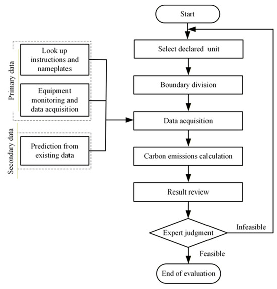
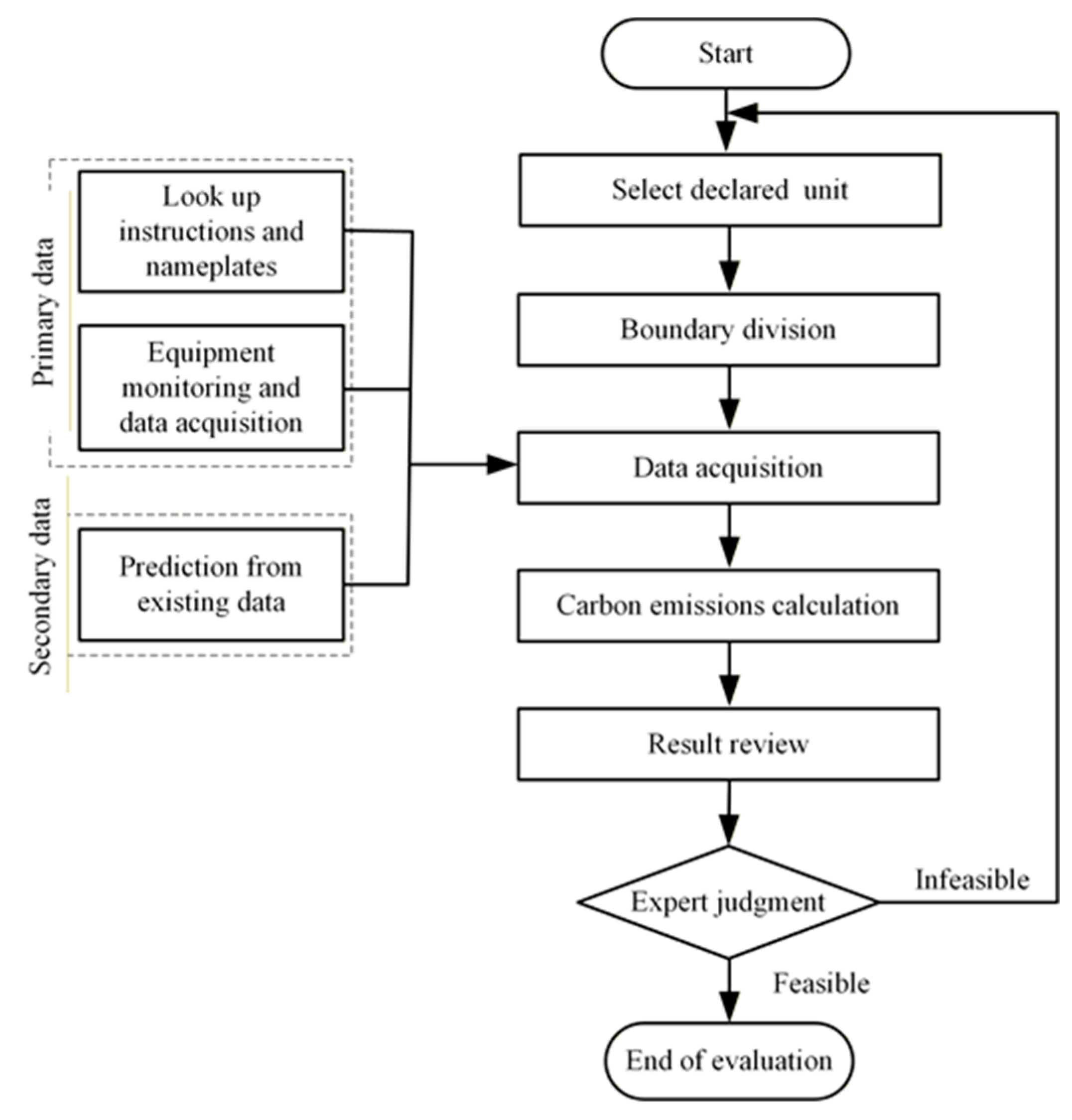
The whole-life-cycle carbon-emission assessment process of machine tools is shown in Figure 1. Before evaluation, a reasonable and targeted declared unit should be chosen. Reasonable declared units can fully reflect the processing capacity of the machine tool, and at the same time make the carbon-emission evaluation between the same type but different-sized machine tools comparable. Subsequently, the boundary of the system is divided, which takes into account environmental factors, research width and depth. Data acquisition includes both carbon-emission activities and carbon-emission factors. At the same time, the differences in the same-level data caused by regions, circulation modes and production processes should be considered. Based on these data, carbon emission of machine tools in the whole life-cycle analysis can be calculated. Calculation results are checked with the quality balance of input and output to ensure the accuracy of evaluation. Subsequently, there is an expert review phase; if the expert judges that the evaluation results are not feasible, the evaluation will be re-made; if the evaluation results are feasible, the results can be released. The results of life-cycle carbon-emission evaluation have a strong practical significance for the lightweight design of machine tools, low-carbon design, and improved low-carbon emission performance of mechanical products and processing.
Figure 1.
Carbon-emission assessment process for machine tool life cycle.
- (1)
- Evaluation purpose, scope and object determination
The aim of life-cycle carbon-emission assessment of machine tools is to promote enterprises or individuals to choose more time-saving, energy-saving and environmentally friendly processing machinery or processes, to reduce energy consumption and processing time, to reduce greenhouse gas emissions, and to find processing opportunities with low environmental costs and low processing costs. Simultaneously, it can provide a reliable calculation concept and foundation for the upcoming carbon barrier and achieve transformation from qualitative calculation to quantitative calculation. Integrating the concept of green ecology into the process of mechanical product design and machining can not only satisfy the consumers’ right to know, but also further publicize the environmental protection image of enterprises and enhance corporate visibility. The whole-life-cycle analysis of machine tool products refers to the process from the production of raw materials (machine tools, workpieces, tools, coolants, lubricants, etc.) required for the processing of machine tools, through the process of production and processing activities, to the scrap machine tools for resource recycling. It includes the mining, transportation, processing, assembly, maintenance for machine tools, as well as the recycling, disassembly and reuse of machine tools after scrapping.
- (2)
- Declared unit selection
The machine-tool application enterprises vary in size, the types of machine tools are numerous, the processing capacity and scope vary greatly, the degree of numerical control is different, the machine tool size and weight is also different, together with the processing technology, processing parameters, materials to be processed, etc.; these are the direct reasons for the huge differences in carbon emissions. The variability and uncertainty of these factors make life-cycle carbon-emission analysis of machine tools more complex and cause a lack of versatility. Reasonable declared units can fully reflect the carbon-emission characteristics of the machine-tool life cycle and can compare the greenness and sustainability of different machine tools. This part will be explained in detail in the next section.
- (3)
- System boundary determination
The determination of the system boundary is an important part in the machine life-cycle carbon-emission evaluation. Different system boundaries mean different calculation categories and contents, which will directly affect the accuracy of the results to be evaluated. The boundaries of the life-cycle assessment system are influenced by factors such as research objectives, intentions, depth and breadth of study. The system boundary of life-cycle carbon-emission assessment for machine tools with complete coverage should include unit processes such as raw-material mining and production processing, component manufacturing, transportation, assembly, usage, scrap and waste disposal. The key principle for judging whether it is within the system boundary is whether it has substantial carbon emissions. That is, whether a process or parts will directly or indirectly generate carbon emissions during the production, usage and reuse of machine tools is the judging principle; if carbon emissions are generated, they should be included in the system boundary.
- (4)
- Data collection
Activity-level data and carbon-emission-factor data are required for the whole-life-cycle carbon-emissions analysis in machining processes. Activity-level data refers to all resources and energy involved in the life-cycle analysis of machine tools, including the input and output of resources during machine-tool production, parts manufacturing, energy usage, dismantling, recycling and disposal of scrapped machine tools. Carbon-emission factors refer to the equivalent carbon emissions produced by energy/resources per unit mass/volume in the process of preparation or usage. That is to say, the carbon-emission factor can convert the activity data on energy, resources and waste in the machining process into equivalent greenhouse-gas emissions. There are two sources of activity level data and carbon emission factor data, primary and secondary respectively. The primary data is a direct measurement or statistical data from the internal or supply chain during the life-cycle analysis of machine-tool component production. In contrast, secondary data refers to non-direct measurement, based on the comparison of primary data for similar products or processes (such as industry report data). In the data-collection process, the primary activity-level data of each energy and resource needs to be collected according to the boundary conditions of the carbon-emissions calculation. In general, in order to ensure the reliability and accuracy of the data, and to truly understand the actual carbon emissions of the machining process, the primary data should be collected and used as much as possible.
- (5)
- Calculation and review
Carbon-emissions calculation in life-cycle analysis should follow the standard process (see Appendix A). It is important to select the data source suitable for the region and the machine tool, which will directly affect the accuracy of the calculation. After calculation, the results should be checked with the principle of mass balance to ensure the accuracy of energy flow, resource flow and waste logistics calculation.
- (6)
- Expert judgment
Because of the variety of machine tools, the different geographical distribution, the changeable processing technology and parameters, and the diversity of data sources, it is necessary to invite experts to review the evaluation results to determine whether the results are reliable. The evaluation denied by experts needs to be re-evaluated; the approved results can be published.
3. Selection of Declared Unit
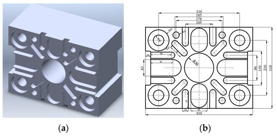
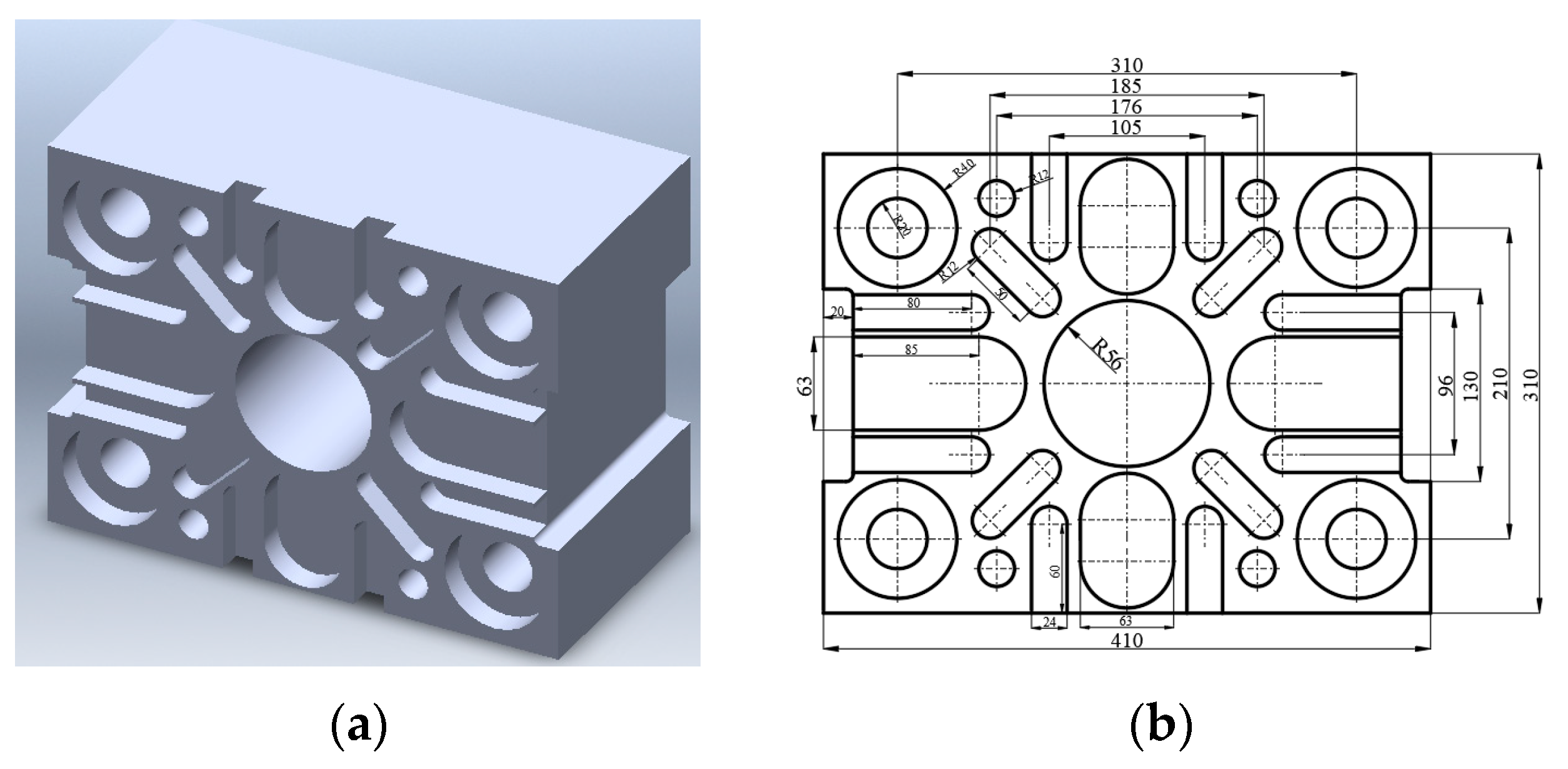
In this paper, the declared unit refers to the key indicators used to declare carbon emissions during the life-cycle phase of machine tools; concretely speaking, it refers to being processed on a certain machine tool based on certain processing technology, processing parameters, and processing specifications. In the life cycle carbon emission assessment of machine tools, for dedicated machine tools, the specified product is processed throughout the life course, and the processing technology, process parameters, product size, etc., are all established, so the workpiece to be processed can be selected as the declared unit. For example, when a specific type of gear is machined in the entire service cycle of the CNC gear hobbing machine [20], it is more reasonable to select the single gear as the declared unit. It is easier to collect relevant data and to calculate carbon emissions, and it can truly reflect carbon emission characteristics of the machine life cycle. However, for most machine-tool application companies, the processing areas of machine tools is wide and varied, and the materials to be processed, process planning and processing parameters are uncertain, so the machine-tool power varies greatly in machining processes. It is unreasonable to simply select the average machine-tool power for a period of time as the basis for calculating carbon emissions in the whole life cycle, and it is easy to cause huge deviation between the estimated value and the real situation. For this type of non-special machine tool, this paper uses the standard part as the declared unit to evaluate the life-cycle carbon emissions of machine tools. The standard part is a part that contains several features and is processed according to standard specifications such as machining process and processing parameters. The topographical features, complexity, and size of the standard parts are closely related to the machine type, size, industry characteristics of machine tool users, and the size of the parts to be processed. Therefore, this paper believes that the design of the standard part is in the industry background of machine-tool application enterprise, according to the type and size of the machine tool, statistical analysis of the frequency and processing parameters of the machine tool’s parts characteristics, and analysis and discussion with other units in the industry to optimize the design. Based on this procedure, the structural shape, size, processing technology and processing parameters of the standard part can be determined. For example, this paper takes two heavy-duty floor-milling boring machines produced by Qiqihar No. 2 Machine Tool (Group) Co., Ltd. (Qiqihar, China) as an example for life-cycle analysis. Through the statistical analysis of the actual processing situation, and consulting the company’s technical personnel, the standard part [21] shown in Figure 2 was designed as the declared unit of the machine-tool life-cycle carbon-emission evaluation, which can accomplish the comparability between machine tools of the same type but different sizes, and facilitate the normalization of evaluation criteria. Therefore, this paper proposes a general life-cycle carbon-emission assessment system based on declared units, which can effectively solve the problem of inconsistent evaluation standards between machine tools. At the same time, it is considered that the structural features of the standard part in declared units should be designed according to the type of turning, milling, drilling and grinding, and the nature of machine-tool application enterprises, and standardized the processing technology, processing path, cutting parameters and processing accuracy as well. Meanwhile, the standard part can be designed into a set of forms with the same characteristics but different sizes to complete the normalization of evaluation according to the difference in machine tool processing abilities. For highly customized machine tools, where the machining objects are highly specialized and the processing tasks are not stable, a single standard part may not be sufficient to represent the typical energy-consumption structure. In such cases, a set of standard parts may be required, or a specified product can be selected as the declared unit. Compared with the general LCA method, the general life-cycle carbon-emission assessment system based on declared units proposed in this paper shows certain advantages in terms of evaluation unit, comparability between different machine tools, repeatability, and applicability, as shown in Table 1.
Figure 2.
Standard test sample model: (a) 3D model; (b) 2D model.
Table 1.
Comparison with General LCA method.
The following design guidelines are required during the standard part-design process in a declared unit:
- (1)
- It can reflect the requirement of a machine tool’s processing ability, processing accuracy and so on.
- (2)
- It can reflect the carbon-emission level of the whole machine tool and ensure the repeatability of the results.
- (3)
- The processing process should include carbon-emission characteristics of each stage.
- (4)
- Comprehensive consideration of the main factors affecting the carbon-emission characteristics of machine tools, and fully reflected in the test sample and test process, such as the size of the sample, the accuracy level, the characteristics of the parts, the use of coolant, tool wear, processing parameters, etc.
4. Life-Cycle Assessment System of Machine Tools
4.1. System Boundary Division
Machine tools are an intricate complex of mechanical, electrical and liquid, mainly composed of the main engine, numerical control device, driving device and auxiliary device. The main engine is the body of machine tools, which is the mechanical part for cutting, including mechanical parts such as the lathe bed and column. The numerical control device consists of both hardware and software, and is the core device of machine tools, used for inputting and compiling programs, and for the motion-control function by data conversion and interpolation. The driving device is the driving force of machine tools, including the spindle drive unit and feed unit; it is controlled by the numerical control device for locating linear movement and space movement. Auxiliary devices are supporting facilities to ensure continuous and reliable operation of machine tools, such as chip-removal devices, lighting, cooling lubrication devices and so on.
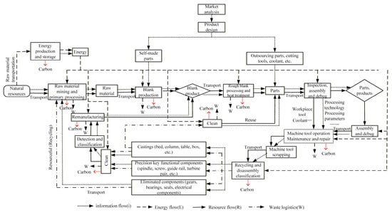
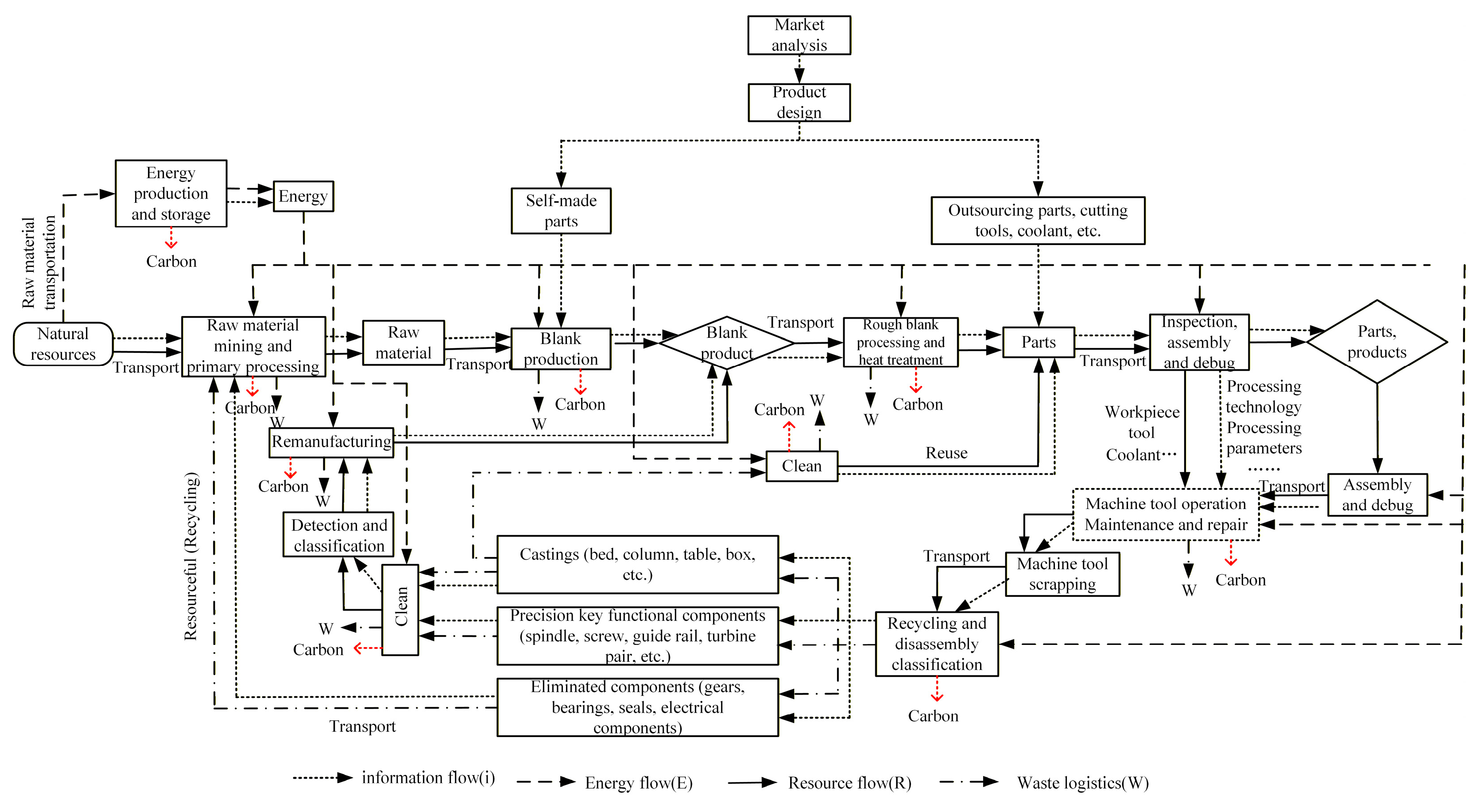
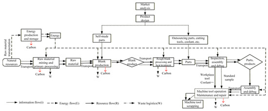
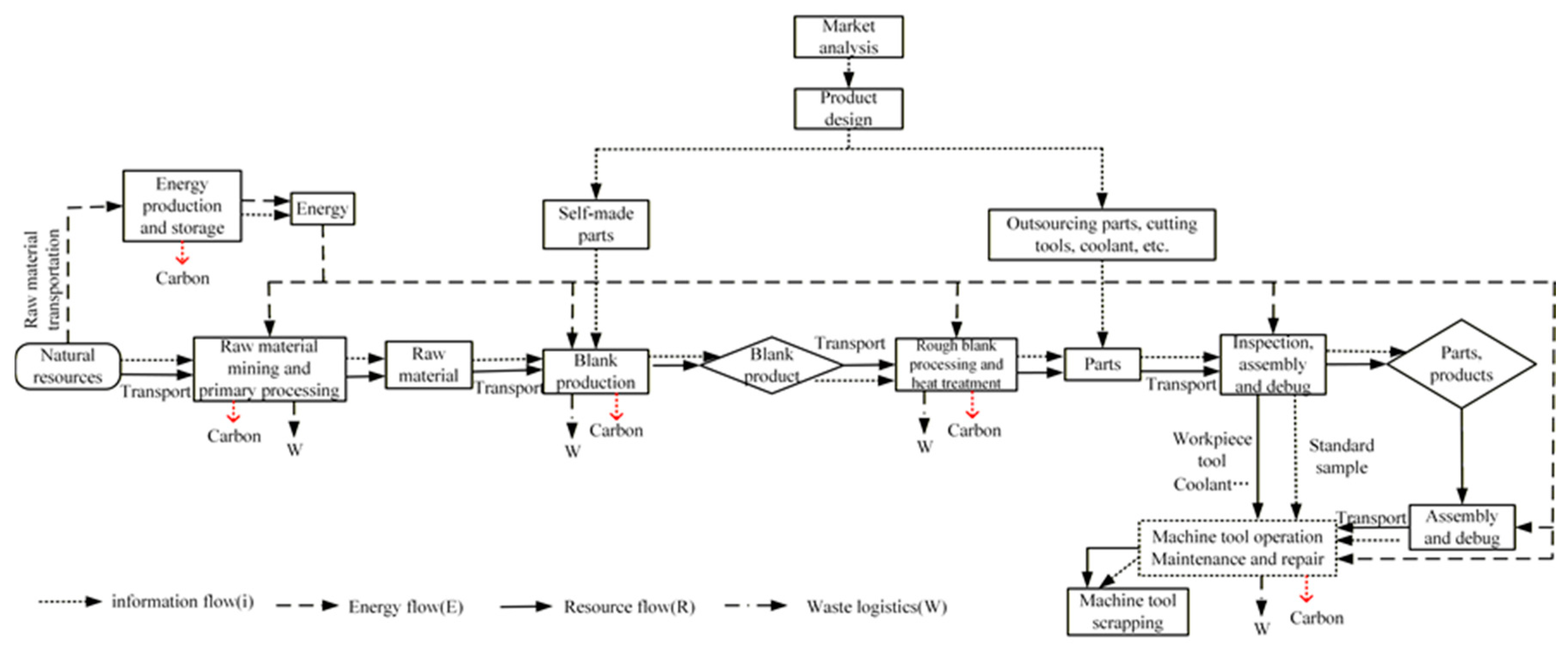
The general production process of machine tools is as follows: understanding customers’ needs—product design—standard parts selection—production design—engineering drawing—bought-in components order—casting, forging and welding—self-made parts processing—assembly and commissioning of machine, electric, liquid and gas components—final assembly, test—trial cut—adjustment—disassemble, maintenance, packing, shipment—assemble and debug at customer’s plant—trial cut—final acceptance. The life-cycle analysis of machine tools should include the phases of raw-material extraction, rough production and heat treatment, assembly, machining process, product discarding, recycling and reuse of machine tools based on life-cycle theory combined with the production process of machine tools. All phases are associated with energy consumption, resource utilization, or waste generation which does negatively affect the environment. The iERWC boundary model [22] in machine tools based on life-cycle theory was built, which can convert energy flow (E), resource flow (R), waste logistics (W) into carbon emissions (C) based on information flow (i), as shown in Figure 3. According to the definition in ISO 14040, the cutoff criteria refer to the specification of the amount of material or energy flow or the level of environmental significance associated with unit processes or the product system to be excluded from a study. Moreover, the cutoff criteria used within a study should be clearly understood and described. Therefore, in this study, if carbon emissions of any single life-cycle stage account for ≤1% of the total life cycle carbon emissions, this stage can be treated as negligible.
Figure 3.
System boundary division based on iERWC [20].
4.2. Analysis of Carbon Emissions at Various Stages
The factors that cause carbon emissions are different in various life-cycle phases of machine tools. The different factors include different effects on the environment even if consuming an equal amount of resources, energy, or completes equal number of tasks. Therefore, the life-cycle carbon emissions in machine tools are divided into five parts based on the analyses of distribution on carbon sources in the whole life cycle of machine tools; that is, carbon emissions from machine-tool parts, carbon emissions in the phase of assembly, carbon emissions in the phase of transportation, carbon emissions in the phase of application, and carbon emissions in the phase of disposal and remanufacture.
4.2.1. Carbon Emissions from Machine-Tool Parts
Machine-tool parts include two parts; one is the bought-in components like standard parts, including motor, pump, valve, bolt, CNC system, wires and so on, which can be used directly after procurement. This part of carbon emission data directly comes from suppliers. The other is self-made parts, which are required to meet the design needs by themselves through casting, forging, welding, turning or milling process besides standard parts. Obviously, techniques such as casting, stamping, cold/hot rolling, turning, milling and grinding, surface treatment and tempering may be involved in self-made parts processing. The document displays that electrical energy consumption in mechanical manufacturing process is the main carbon emissions source [23]. However, cutters consumption (tool failure caused by wear, breakage) in the turning or milling processes is also an important cause of carbon emissions. When calculating the carbon emissions of electrical energy, embodied energy [24] can be introduced for plastic-deformation technology such as stamping, and specific energy for turning and milling technologies. Therefore, carbon emissions of self-made parts consist of two parts: carbon emissions produced by plastic deformation and carbon emissions produced by turning or milling process. So,
where is carbon emissions caused by electrical energy consumption of self-made parts. is material to be processed of self-made parts. is plastic-deformation type. is cutting-technology type. is the weight of case i material for the j plastic deformation process. is the embodied energy consumption of case i material for the j plastic deformation process. is the amount of removed material of case i material for the j process. is the specific energy of case i material for the j process. is the carbon-emission coefficient of electrical energy.
The carbon-emission factor of electrical energy will vary due to the preparation process. Even if all of them are thermal power generation, the carbon emission factors of different regions are still different, which will lead to differences in the carbon emissions caused by electricity consumption. Detailed regional power carbon-emission factors can be referred to in the data published by the National Bureau of Statistics of China [25]. This paper uses the power emission coefficient of 0.7802 kgCO2/kwh in northern China.
From the perspective of machine-tools constituents, the cast iron and steel on machine tools accounts for over 90% of the entire machine-tool weight. Generally, the machine-bed structure parts, such as bed, column, worktable and so on, are often made of cast iron; the moving components, such as spindle, leading screw, gear and so on, are often made of steel, and part of them may also be made of alloy. The weight of cast iron, steel and copper can be calculated according to BOM provided by machine-tool enterprises; data on carbon emissions caused by raw materials can be obtained, combined with carbon emission coefficients released by the National Statistical Bureau.
where is carbon emissions caused by raw materials. is the consumption of case i raw materials. is the carbon-emission coefficient of raw materials.
Calculation of carbon emissions caused by chips, cooling fluid and lubricating oil is just the same as ; they are all calculated by the weight of each resource multiplied by the corresponding carbon-emission factors.
To summarize, carbon emissions of self-made parts processing include carbon emissions of standard parts, carbon emissions coming from the consumption of electricity, materials and cutting tools of self-made parts, then
where is carbon emissions caused by self-made parts. is the sorts of standard parts. is carbon emissions of case i standard parts.
4.2.2. Carbon Emissions in the Phase of Assembly
When the machine-tool parts are processed or prepared properly, the machine-tool assembly can be carried out.
The machine-tool assembly can be divided into two categories. One type is the assembly in the machine tool-production enterprise. Usually, the manufacturers will perform assembly, precision detection, function adjustment and trial operation before shipment. The environmental impact of this part belongs to the phase of assembly. The other type is assembly in the purchaser’s factory, and the assembly process is similar to the process in the production enterprise. Considering the machine-tool assembly process, the following activities may cause carbon emissions: construction of workshop according to the requirements of machine tool manufacturers, machine-tool assembly, trial cutting, precision adjustment, function adjustment of machine tool (lighting, coolant switch, travel limit protection and so on), trial cutting. But this part of carbon emissions is scattered, miscellaneous and not much. Carbon emissions in the assembly phase can be obtained according to energy consumption, assembly man-hours, assembly quantities and other statistical data in assembly workshop for some time. The calculation formula for carbon emission in the assembly phase is as follows,
where is carbon emissions in the assembly phase. is total energy consumption in the assembly workshop. is the assembly hours of current machine tools. is the assembly quantities of case k machine tools. is the assembly hours of case k machine tools.
4.2.3. Carbon Emissions in the Phase of Transportation
Carbon emissions from all transportation during the whole life cycle of machine tools should be calculated. The phase of machine-tool transportation includes not only the transportation of bought-in standard parts but also the transportation of raw materials used for self-made parts, and even the transportation of crown blocks in the factory. When the machine tool is finished, it is necessary to carry out transportation between the manufacturer and the customer. The above-mentioned transport will produce carbon emissions due to the consumption of electric energy or other energy sources, such as gasoline and diesel.
According to the intensive degree of carbon emission in the transportation stage, carbon emission in the phase of transport can be divided into two parts: the transportation of raw materials/components and the transportation of finished products. Both of them are calculated by multiplying the carbon-emission coefficient by the material/energy consumption. The difference is that part of the carbon emission in the phase of transport of raw materials/components is the transportation of parts related to machine-tool manufacturing, and the carbon emissions are small. It can be calculated by statistical means or ignored. Carbon emissions of the finished product transportation part consists of the transportation between the manufacturer and the customer, so the carbon emission of machine tool transportation is as follows,
where is carbon emission in the phase of transport. is transportation modes used in the course of transportation, such as shipping, railway transportation, road transportation or movement by crown block in the factory. is the miles or electricity consumption for case i transportation mode. is carbon emission factors of case i transportation mode.
4.2.4. Carbon Emissions in the Phase of Application
Carbon emissions in the phase of application in the whole life-cycle mainly comes from the consumption of electric energy. Although the usage of cutters, coolant, lubricants and chips generation will also produce carbon emissions, the research intention of this paper is carbon emissions of machine tools in the whole life-cycle. However, carbon emissions from coolant, lubricants and chips generation belong to the parts to be processed on the machine tool; therefore, this part should not be included in the whole life-cycle of the machine tool [26]. In metal cutting, cutters are consumable and will be replaced due to tool wear or tool failure. The carbon emissions caused by cutter consumption are allocated over the tool usage life, and the cutter-related carbon emissions in the phase of application can be expressed as follows:
where is the carbon emissions allocated to cutter consumption; is the cutting time of the machining task; is the carbon-emission factor of the cutter; is the cutter mass, and is the tool usage life until replacement, and the formula is
Tool wear may influence cutting-energy consumption and shorten tool usage life; however, since carbon emissions in the phase of application are dominated by electric energy consumption and the basic power consumption and auxiliary systems account for a large proportion of the total energy consumption of machine tools, the influence of tool wear on the total carbon emission in the phase of application is small and can be ignored at the screening level [27,28].
The energy consumption in the process of mechanical processing is usually divided into three parts [29]: constant-energy consumption, response-energy consumption and cutting-energy consumption. Constant-energy consumption is the energy consumption when the machine is powered on but without any movement; this includes the CNC system, cooling system, lighting system and cutting chip collecting and transferring system. The characteristic of this part is that it will consume energy when the system or function is on, but will not if it is off. Response-energy consumption is energy consumption caused by the change in spindle and feed instruction; this part of energy consumption is greatly influenced by spindle speed, and the influence of the feed shaft can be ignored. Cutting-energy consumption is related to the material machined, cutting parameters, material and parameters of the cutters. Then carbon emission in the phase of application can be expressed as follows [22]:
where is the basic power consumption of case i part in machine tools. is the duration of the machine-tool power on. is the state of case i component at moment; it will be 1 when it is active but 0 when it is inactive. is response energy consumption at time t. is the duration for response-energy consumption. is cutting power. is the duration for cutting-energy consumption.
Energy consumption of peripheral equipment used to ensure and maintain the machine tools normal operation is shared in the workshop, such as the air pump, should be determined according to the ecological footprint of the factory; namely the proportion of the required area by machine-tool operation to the total area of the workshop is equal to the proportion of the peripheral equipment energy consumption to the total peripheral-energy consumption of the workshop. The peripheral equipment such as lighting and central air conditioning are optional conditions for maintaining workers’ activities and have nothing to do with the processing of machine tools, so they should not be counted in the energy consumption of peripheral equipment. Then the peripheral-equipment energy consumption of machine tools is is,
where is the required area of machine-tool operation. is the total area of the workshop. is the total power consumption of peripheral equipment.
Then carbon emission in the phase of application is
4.2.5. Carbon Emission in the Phase of Disposal and Remanufacture
Machine tool products have great value in recycling, reusing and remanufacturing. Machine tools were regarded as a recyclable resource and used as raw material for other products over the past years. In recent years, a growing number of studies have shown that about 80% of parts and components on machine tools can reenter the machine-tool market by remanufacturing to replace some new parts. Thus, it can reduce segments of the machine-tool life cycle by saving raw material and rough production processes, so it can reduce the life-cycle carbon emissions. Some of the non-reusable parts can be recycled as raw materials to achieve resource recovery and reduce carbon emissions to a certain extent.
where is carbon emission in the phase of disposal and remanufacture. is the species of remanufactured parts. is carbon emissions of case i replaced parts by remanufacturing. is carbon emissions in the manufacturing process by remanufacturing of case i replaced parts. is the species of recycled materials. is carbon emissions of case j recycled materials. is carbon emissions in the recycling process of case j recycled materials.
5. Case Study
5.1. Application
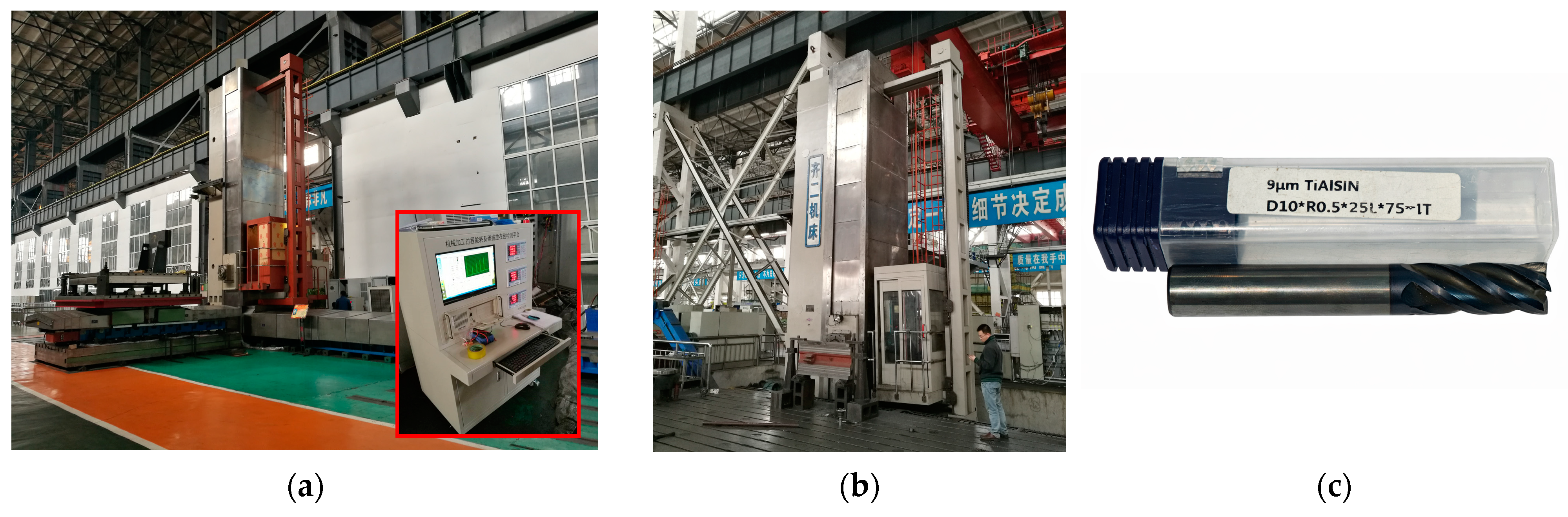
Two floor-typed milling and boring machine tools (model TK6513 and a self-made self-employed one which was named TEST01 for convenience) produced by Qiqihar No. 2 machine tool (Group) Co., Ltd. were selected for analyzing life-cycle carbon-emissions analysis of machine tools (Figure 4). At present, machine-tool recycling and remanufacturing technology is not mature, and there is also no relevant practical data. Then after the machine tool is scrapped, machine tools will be recycled as waste materials. Therefore, the boundary conditions of the two machine tools based on iERWC system are shown in Figure 5. Table 2 shows the main technical parameters of machine tools. Table 3 displays the material composition and weight of machine tools which can be found in the list of BOM. Road transportation is regularly chosen as a transportation mode to deliver machine tools; TK6513 was transported from producer to consumer, whereas TEST01 needs no delivery. The energy-consumption measurement and data are detailed in ref. [21]. Carbon emissions from machine-tool parts and carbon emissions in the phase of assembly are not affected by factors such as producer and consumer or machine-tool usage, which can be seen as a fixed value. Carbon emissions in the phase of transport are affected by regional factors, transportation modes and transportation distance as the direct factors. Carbon emissions in the phase of disposal and remanufacture are obviously influenced by laws and regulations. The higher the reutilization ratio of parts on machine tools, the less the environmental impact, the more friendly the environment. In contrast, carbon emissions in the phase of application are completely different from the above phases; these are variable carbon emissions which will not be fixed in pace with fixed producer and consumer or material properties. Rather it is closely related to the production efficiency and the use time, which is affected by actual working conditions.
Figure 4.
The floor-typed milling and boring machine tools and measuring instruments: (a) TK6513 and measuring instruments; (b) TEST01; (c) Milling Cutter.
Figure 5.
The boundary conditions based on iERWC system.
Table 2.
The main technical parameters of machine tools.
Table 3.
The material composition and weight of machine tools.
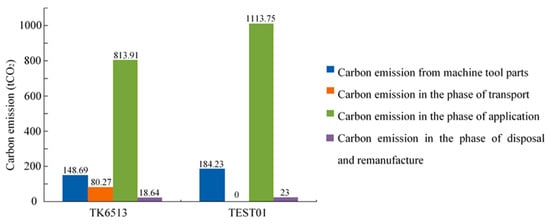
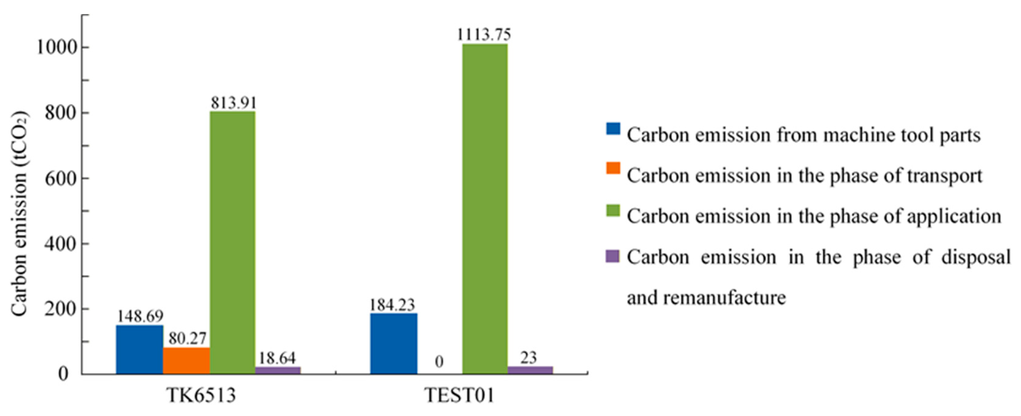
The case is to study the life-cycle carbon-emission characteristics of floor-typed milling and boring machine tools. Since they are universal machine tools, the material type, quantity, type and processing parameters to be processed are uncertain. The standard part should be selected as the declared unit to analyze the life-cycle carbon-emission characteristics based on Section 2. The standard part in this paper (Figure 2) was designed by referring to ‘test method for electric power consumption’ (JIS TS B 0024-1:2010) developed by Japan Standards Association, through statistical analysis of the actual processing situation of the factory, and synthesized considering the data from the technical staff of the company and advice coming from the technical staff of China First Heavy Industries, which is in the intra-industry. The standard part designed in this case integrates typical machining features, including holes, slots, counterbores, and steps, with occurrence specific frequency proportions of 29.0%, 38.7%, 25.8%, and 6.5%, respectively. The material of this standard part is HT300, and its specific dimensions are shown in Figure 2b. The standard part also includes the process specifications, which can make the standard part become a more industry-wide declared unit of carbon emissions in the whole life cycle of machine tools. The results of carbon-emission calculation for each stage of the whole life cycle are shown in Figure 6.
Figure 6.
Carbon emissions in different stages of life cycle.
5.2. Discussion
From the data in Figure 6, life-cycle carbon emissions of TK6513 and TEST 01 are 1067.54 tCO2 and 1320.98 tCO2 separately; carbon emission in the phase of application are 813.91 tCO2 and 1113.75 tCO2 separately, and accounted for 76.24% and 84.31% of carbon emissions in the machine life cycle. It can be seen that carbon emissions in the phase of application account for the vast majority of the total carbon emissions, which is the main carbon-emission source in the life cycle of machine tools. Therefore, it is of great significance to study low-carbon processing through parameter optimization. The processing technology and cutting parameters of the standard parts processed by the two machine tools are the same in this case, so the useful work is the same. It can be ascertained that the difference in carbon emissions between two machine tools is caused by the difference in non-cutting power of machine tools. Compared with TEST01, TK6513 is smaller, the auxiliary facilities and devices needed may be less, the motor power and response-energy consumption will also be smaller, so the non-cutting part of the energy consumption will be smaller. Therefore, it is necessary to match the tasks in the workshop with machine tools and processes. Reasonable process planning and job shop scheduling can not only improve processing efficiency but also minimize machine standby time and idle time to achieve low-carbon processing. At the same time, the selection of machine tools matching the processing tasks, the reasonable cutting parameters and processes will effectively and substantially reduce energy consumption.
Carbon emissions from machine-tool parts account for 13.93% and 13.94% of the total-life-cycle carbon emissions of machine tools respectively, and most of the carbon emissions come from the processing and preparation of raw materials for machine tools, etc. The machine tool itself has a limited number of parts. The optimization of processing technology and processing parameters can only promote energy-saving and emission-reduction to a certain extent, and the reduced space is limited. However, if the machine bed and guideway are coming from remanufacture of discarded machine tools, or carrying out lightweight design of machine tools, then carbon emissions from these parts will present a step-type-decrease trend which has heavy energy-conserving space. In our case, using recycled cast iron and steel for the corresponding machine tool parts can reduce carbon emissions by 50.5 tCO2 for TK6513 and 62.83 tCO2 for TEST01.
Carbon emissions in the phase of transport account for 7.52% and 0% of life-cycle carbon emissions of machine tools respectively. This part is directly affected by the location of the manufacturer and the customer, which is inevitable. Changing the mode of transportation may be the only way to reduce this part of carbon emissions.
At present, the remanufacture of discarded machine tools is limited by remanufacturing levels and people’s beliefs; scrapped machine tools will be disposed as common waste steel after abandonment, so the environmental cost and expense of the recycling process are high, and the environmental friendliness is poor. Therefore, the remanufacturing of discarded machine tools will be the trend for future development.
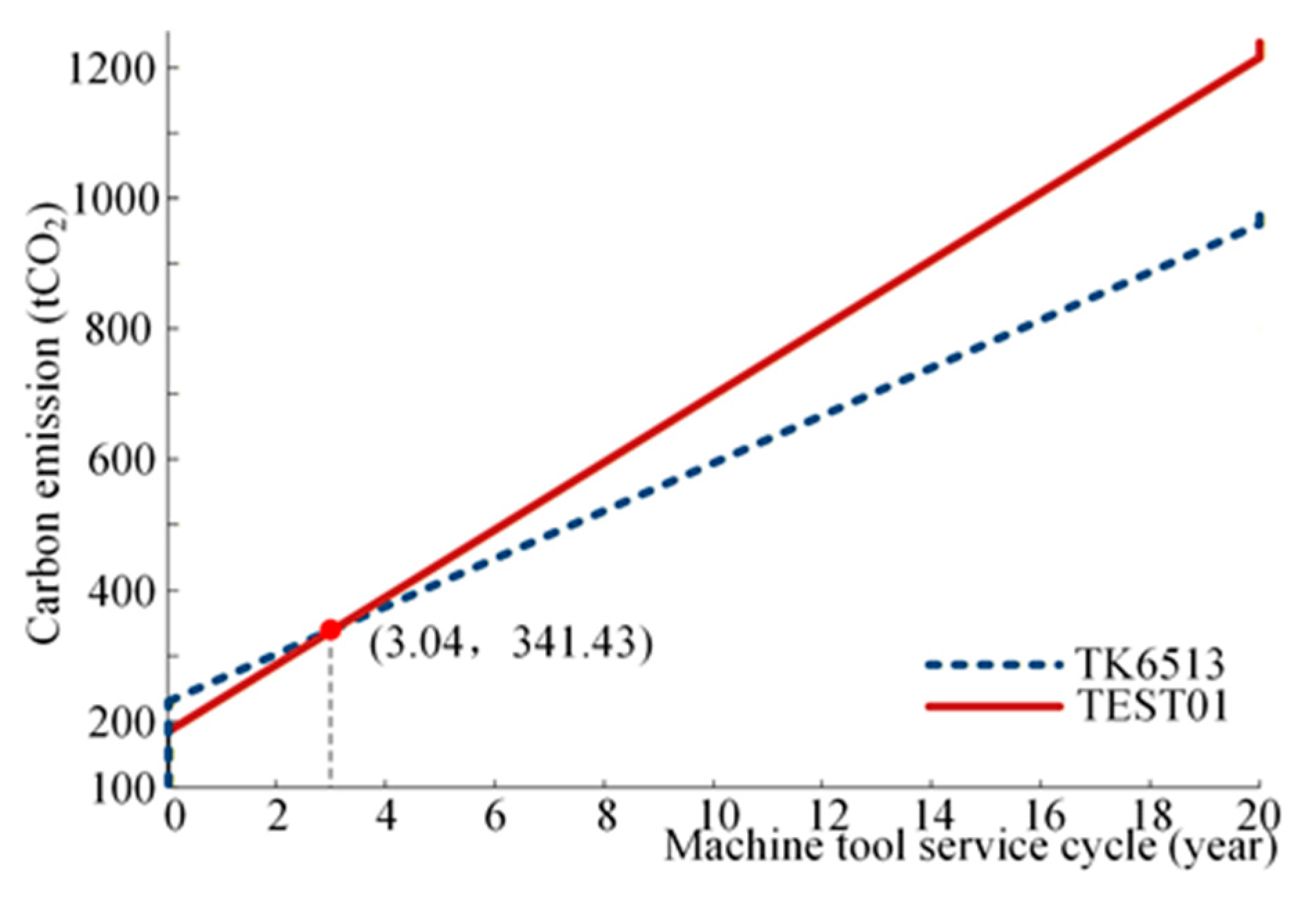
The variation curve of carbon-emission characteristics of various life-cycle phases in machine tools with time is plotted in Figure 7; it is not hard to see that TK6513 and TEST 01 have already produced 228.96 tCO2 and 184.23 tCO2 carbon emissions, respectively, before being put into use. This is the part of carbon emissions that already existed before machine tools begin service, since this is the sum of carbon emissions from machine-tool parts, carbon emissions in the phase of assembly and carbon emissions in the phase of transport. It can only be lowered as far as possible but cannot be eliminated. The weight of TK6513 is lighter than TEST 01, then carbon emissions from machine-tool parts of TK6513 are less than that of TEST 01. But TK6513 needs to be transported from Qiqihar to Sichuan through road transportation, thus the diesel fuel consumed will produce a lot of carbon emissions. However, TEST 01 has no carbon emissions in the phase of transport because it is a self-made and self-used product without the need for transportation. After 20 years of the service cycle, there is also a sharp increase in carbon emissions; these are carbon emissions generated by the heat treatment of parts or components that can be recycled or reused in the phase of disposal and remanufacture. If some parts or components of waste machine tools are remanufactured, this part of the carbon emissions will be greatly reduced, and will reduce required carbon emissions of new machine tools, and it will be a good choice for both energy saving and emission reduction or costs accounting.
Figure 7.
Two machine tools’ life-cycle carbon-emission characteristics.
The two slant-line segments that span the 20-year service period of the machine tool are carbon-emission curves in the phase of application (Figure 7). It can be found that the carbon emissions of the TEST01 machine tool is higher than that of TK6513 machine tool after the end of its service life cycle. The reason for this phenomenon is that TEST01 is larger than TK6513, so its carbon emissions per unit time in the service phase is larger than that of TK6513. This led to the phenomenon that the latter came to the fore over the whole life cycle. And it is easy to find that the slope of TK6513 is less than that of TEST 01. That is to say, carbon emissions produced by TK6513 per unit time are less than those of TEST 01. It was also found that the two curves intersect at approximately the third year of service, indicating that their cumulative carbon emissions are equal at that time. Before the intersection, the cumulative emissions of TK6513 are higher than those of TEST01; after the intersection, they become lower.
6. Uncertainty Analysis
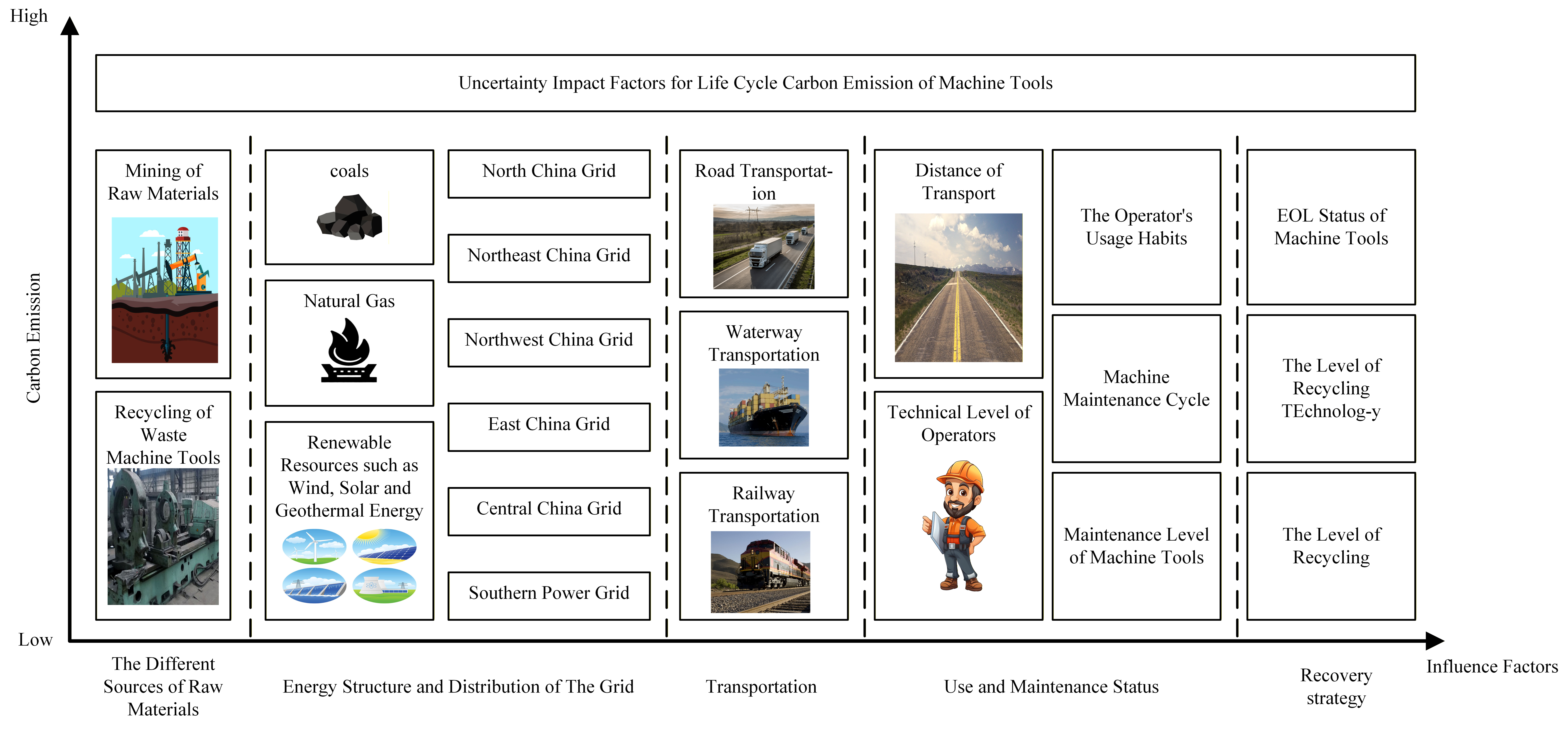
This paper provides a reference evaluation idea, evaluation system and calculation method for the life-cycle carbon-emission evaluation of machine tools. However, when the people in different countries and regions conduct the life-cycle carbon-emission evaluation of machine tools, the carbon emissions of the life cycle will vary even on the same type of machine tool. This is because there are some uncertainties in the life-cycle carbon-emission assessment of machine tools. For example, service life of machine tools, processing parameters, energy structure, raw-material source of self-made parts, etc., will cause this uncertainty. This uncertainty affects the credibility of the calculation of carbon emissions in the whole life cycle of machine tools, and it also has certain constraints on the calculation, as described next (Figure 8).
Figure 8.
Uncertainty Impact Factors for Life-Cycle Carbon Emission of Machine Tools.
- (1)
- Material sources
The self-made parts are usually cast and forged by factories themselves; of course, some enterprises also adopt the custom outsourcing method. But in either case, different sources of raw materials produce different amounts of carbon emissions. For example, carbon emissions from the use of recycled metal casting machine beds are much smaller than those from raw stone mining and refining casting machine beds. The carbon emissions generated by the dismantling and reprocessing of scrap machine tools generate less carbon emissions from the recycling methods of resource recycling. In addition, the standard parts produced by different manufacturers will cause different carbon emissions even when using the same materials, the same size, the same functional parts, due to the different sources of raw materials, processing technology and other factors. In this case, the carbon emissions of cast iron of TK6513 is as high as 108.9 tCO2, but only a small amount of carbon emissions are produced in the processing and transportation phases if the machine-bed parts come from scrap machine tools.
- (2)
- Energy-resource structure
Carbon emissions of small and medium-sized machine tools in the application stage account for the vast majority of the machine-tool life cycle, usually accounting for more than 96%. Energy includes not only primary energy directly obtained from nature, but also secondary energy after man-made transformation. The carbon-emission factors of primary energy have universality; there is little difference among different LCA databases and little uncertainty. By contrast, the preparation of the secondary energy needs to consume energy, and its carbon-emission factor is closely related to the preparation process. If the preparation process of the same secondary energy is different, then its carbon-emission factor may be quite different; there is great uncertainty. For example, hydroelectric power produces almost no carbon dioxide. In contrast, the preparation process of thermal power generates a large amount of carbon emissions. In this case, the carbon-emission factor of energy is 0.7802 kgCO2/kwh in the Northern Power grid; however, if 0.6433 kg CO2/kwh of the Northwest Power Grid is used, the carbon emissions will be reduced by 128.86 tCO2. Therefore, choosing energy with a low carbon-emission factor has great energy-saving potential. In addition, a fully renewable electricity scenario should also be considered, in which the electricity carbon-emission factor can be assumed to be close to zero. In this case, the carbon emissions caused by electricity consumption in the use stage will be almost eliminated, and the total-life-cycle carbon emissions will drop significantly. Specifically, the total emissions of TK6513 will decrease from 1067.54 tCO2 to about 333.2 tCO2, and the total emissions of TEST01 will decrease from 1320.98 tCO2 to about 286.8 tCO2.
The sensitivity of different stages in the machine-tool life cycle to the regional electricity emission factor also varies. In this study, the life-cycle carbon emissions in machine tools are divided into five stages. The stages that are directly affected by the electricity emission factor include the machine-tool parts production stage, the assembly stage, and the application stage. The transportation stage and the disposal and remanufacture stage are quantified using material-related and fuel-related emission factors. In our case study, there is no self-made parts manufacturing in the parts production stage, and the assembly stage is subject to the cut-off rule; therefore, the carbon emissions caused by electricity consumption in these two stages are negligible. Consequently, across different regions, the carbon emissions in the application stage can vary significantly due to the selection of the electricity emission factor. The carbon emissions in the application stage can be briefly expressed as C = E × EF. We define the sensitivity coefficient with respect to the electricity emission factor as SEF = ∂C/∂EF, which equals the corresponding electricity demand E. In the application stage, the electricity demands E of the two machine tools are 941,220 kWh and 1,325,520 kWh, respectively. Therefore, the application stage is the life-cycle stage most affected by changes in the regional grid electricity emission factor, while the other stages show zero sensitivity because they do not include an electricity-consumption term in this case. Therefore, the electricity emission factor is a key uncertainty factor, which can greatly influence not only the total carbon emissions but also the contribution structure of different life-cycle stages.
- (3)
- Transportation
In the whole life cycle of the machine tool, the standard parts of machine tools, the raw materials of self-made parts, the finished machine tools, etc., need to be transported and distributed. But these outsourced parts, raw material suppliers, batches and so on are different, the methods and distance of transportation are uncertain, so the carbon emissions generated are very uncertain as well. In addition, the self-made parts need to transship in the factory many times in the process of manufacturing, the distance of each dispatch is uncertain, and the technical level of operators is uncertain, which will cause the uncertainty of carbon emissions in the transportation stage. In this case, TK6513 will produce 80 tCO2 of carbon emissions only from the manufacturer to the buyer, while TEST01 saves this part of carbon emissions; the gap is obvious.
- (4)
- Use and maintenance status
The machine will be in service for several years from use to final scrap. The operator’s usage habits, machine maintenance cycle and level will have a certain impact on the service life of the machine; that is, the machine-tool life is uncertain. This uncertainty will directly affect the carbon emissions of the machine-tool usage stage. As far as the whole life cycle of the machine is concerned, the better the operator’s habits and the better the equipment maintenance, the longer the service life of the machine will be, and the greater the total carbon emissions during the evaluation period, but the average carbon emissions will decrease. After the machine is put into use, the cooperation among the modules and parts will change from the initial astringency to smoothness, and then to the final worn-out stage. And the annual carbon emissions will show a corresponding decline first and then increase.
- (5)
- Recovery strategy
After the machine tool is scrapped, different disposal methods will cause huge differences in carbon emissions. Influenced by the state of machine tools when discarded, the level of recycling technology and recycling strategy (product-level reuse, component-level remanufacturing, material recycling), the same machine tool has different contributions to the remanufacturing, and its environmental impact is highly uncertain. At present, the level of disassembly technology in China is not high, which means that many machine-tool parts that can be reused in products can only be remanufactured at the component level or only used as raw materials for recycling, which result in low product-recycling efficiency and low environmental friendliness. Recycling and reuse of machine tool products can improve the reuse rate of materials, which is helpful to improve the economic and environmental benefits of products, but remanufacturing level is an uncertain factor.
7. Conclusions
To compare and characterize the life-cycle carbon emissions of different machine tools and address the limited generalizability and non-uniform procedures of existing models, this study proposes a life-cycle carbon-emission assessment system of machine tools based on a declared unit. Following the carbon-emission assessment process, the evaluation starts from selecting a reasonable and targeted declared unit. Then, the system boundary is divided based on the iERWC boundary model with transparent cut-off criteria. Carbon-emission models are established for different life-cycle stages according to the machining characteristics of machine tools. Activity-level data are obtained through well-designed experiments, and the life-cycle carbon emissions are calculated by combining the activity data with the corresponding carbon-emission factors from public databases or manufacturers. Finally, result review is conducted through the quality balance of input and output and expert judgment to ensure the reliability and reproducibility of the assessment. Based on the application field of machine tools to be evaluated and the characteristics of the parts processed, different declared units will be selected to carry out life-cycle carbon-emission assessment to achieve comparability of greenness and sustainability between the same type but different machine tools. The information-flow-based iERWC carbon-emission boundary-division model can effectively avoid the loss of one or some factors in the whole-life-cycle calculation. Carbon emissions caused by electricity consumption in the use phase account for the vast majority of carbon emissions in the entire life cycle. Since the use-phase carbon emissions are calculated by the emission factor, the dominance of the use phase is closely related to the electricity mix. If a fully renewable electricity scenario is assumed, the total-life-cycle carbon emissions of TK6513 and TEST01 will decrease to about 333.2 tCO2 and 286.8 tCO2, respectively, and the main carbon-emission sources will shift to the manufacturing, transportation, and disposal and remanufacturing stages. Moreover, the use of coated cutters affects carbon emission in the phase of application through cutter consumption and replacement requirements, indicating that cutter-related inventories should be integrated with energy accounting when evaluating and optimizing low-carbon machining. It is of great significance to study the parameter optimization in the machining process to achieve energy saving and emission reduction. The case study results also show that lightweight design and remanufacturing can effectively reduce the life-cycle carbon emissions of machine tools. However, the key strategies to reduce varied emissions are to choose low-carbon-emission-factor energy and make the best matches of equipment and production tasks.
Author Contributions
Conceptualization, Z.J.; Methodology, X.L.; Software, Y.S.; Validation, G.Z.; Formal analysis, Y.S.; Investigation, Y.J.; Resources, Y.M.; Data curation, Y.S.; Writing—original draft, Y.S.; Writing—review & editing, Z.J.; Visualization, X.L.; Supervision, Z.J.; Project administration, X.L.; Funding acquisition, Y.M. All authors have read and agreed to the published version of the manuscript.
Funding
Supported by Projects of Joint Fund of the National Natural Science Foundation of China for Enterprise Innovation and Development (U24B2060) and Major Scientific and Technological Achievement Transformation Project of Heilongjiang Province (CG23012) and Heilongjiang Postdoctoral Fund (LBH-Z21166).
Institutional Review Board Statement
Not applicable.
Informed Consent Statement
Not applicable.
Data Availability Statement
The original contributions presented in this study are included in the article. Further inquiries can be directed to the corresponding author.
Conflicts of Interest
Authors Zhipeng Jiang and Guohua Zheng were employed by the company Hangzhou Sino-Deutsche Power Transmission Equipment Co., Ltd. Author Yuxin Jia was employed by the company Zhejiang SUPOR Electrical Appliances Manufacturing Co., Ltd. The remaining authors declare that the research was conducted in the absence of any commercial or financial relationships that could be construed as a potential conflict of interest.
Appendix A. Machine Life-Cycle Carbon-Emissions Calculation
The time for processing the standard parts by TK6513 and TEST 01 was 31 min. The energy consumption is 5.229 kw · h and 7.364 kw · h, respectively. And the corresponding carbon emissions are 4.08 kgCO2 and 5.75 kgCO2, respectively. The factory implements a two-shift system with 8 h per shift. After calculation, 15.48 standard parts can be processed per shift, and 15 standard parts can be processed per machine-tool shift, with the removal of scattered time such as workers’ drinking water. The service life of machine tools is 20 years, and 300 working days per year. The ratio of raw materials for the two machine tools is shown in Table 3, and the carbon-emission factors are shown in Table A1 [30].
Table A1.
Carbon-emission factors.
- (1)
- Carbon emission from machine-tool parts
According to the data in Table 3 and Table A1 and corresponding formulas, the cumulative carbon emissions from components can be calculated. Carbon emissions from machine tool parts of TK6513 are the sum of carbon emissions from cast iron, steel, aluminum alloy and some other materials.
Similarly, the carbon emissions from machine-tool parts of TEST01 can be calculated, and the result is 184.23 tCO2.
Using recycled cast iron and steel to manufacture TK6513 parts has considerable potential for reducing carbon emissions.
Similarly, the reduced carbon emissions from machine tool parts of TEST01 can be calculated, and the result is 62.83tCO2.
- (2)
- Carbon emissions in the phase of assembly
Carbon emissions in the phase of assembly are mainly caused by the energy consumption of some tools during assembly. According to the research in document [5], this part of power consumption is very small, and the two machine tools in the case study belong to the standard type, with standard assembly specifications and skilled experience, then carbon emissions in this stage can be ignored. In addition, according to the cut-off criteria adopted in this case, the assembly phase contribution is below the cut-off threshold. Therefore, from the perspective of the cut-off criteria, the carbon emissions in this stage are also negligible.
- (3)
- Carbon emissions in the phase of transport
Carbon emissions in the phase of transport include raw-material transportation, in-plant transportation and the transportation of the sold machine tools. The transportation in the workshop is mainly by crane and tram, and electric energy is the driving energy. However, this part of the data cannot be obtained from the manufacturer for the time being. The raw materials are purchased in this city, so these two parts are not included for the time being. In this case, the sale and transportation of machine-tool finished products are highway transportation, so the carbon emissions of TK6513 are as follows:
TEST01 is a self-used machine tool, which does not need the transportation of finished products, so the carbon emissions in this stage are 0.
- (4)
- Carbon emissions in the phase of application
In this case, the processing parameters and processing techniques of the standard parts of the two machine tools are specified, so the processing time of the single product is the same. During the application stage, the machine tool consumes cutters. According to the cutter-life calculation formula given above, assuming continuous milling under the same working conditions, the cutter life is roughly estimated to be 50 min, and the carbon emissions caused by cutters consumption over the whole application stage can be approximately 79.57 tCO2. The number of standard parts processed by the two machine tools during their entire life cycle is
The carbon-emission factor of energy is calculated according to the Northeastern Power Grid 0.7802 kgCO2/kWh, and the energy consumption required by standard parts of the two machine tools are 5.229 kWh and 7.364 kWh, respectively.
Then the carbon emissions of TK6513 during the whole life cycle are
The carbon emissions of TEST01 are 1113.75 tCO2.
In this paper, heavy-duty machine tools are selected as research objective. The energy consumption of peripheral equipment such as the air pump mentioned in Section 4.2.4 is rarely used in processing, therefore can be ignored here.
- (5)
- Carbon emissions in the phase of disposal and remanufacture
The machine-tool recycling and remanufacturing technology is still immature, and scrap machine is temporarily recycled after disposal.
Then the carbon emissions of TK6513 in the phase of disposal and remanufacture are
The TEST01 has carbon emissions of 23.0087 tCO2 in the phase of disposal and remanufacture of the whole life cycle.
Table A2.
Carbon emissions of machine tools at different life-cycle stages.
References
- National Bureau of Statistics of China. China Statistical Yearbook 2023; China Statistics Press: Beijing, China, 2023.
- Santos, J.P.; Oliveira, M.; Almeida, F.G.; Pereira, J.P.; Reis, A. Improving the Environmental Performance of Machine-Tools: Influence of Technology and Throughput on the Electrical Energy Consumption of a Press-Brake. J. Clean. Prod. 2011, 19, 356–364. [Google Scholar] [CrossRef] [Scilit]
- Narita, H.; Kawamura, H.; Norihisa, T.; Fujimoto, H.; Hasebe, T. Development of Prediction System for Environmental Burden for Machine Tool Operation (1st Report, Proposal of Calculation Method for Environmental Burden). JSME Int. J. C Mech. Syst. Mach. Elem. Manuf. 2006, 49, 1188–1195. [Google Scholar] [CrossRef] [Scilit]
- Akbari, J.; Oyamada, K.; Saito, Y. LCA of Machine Tools with Regard to Their Secondary Effects on Quality of Machined Parts. In Proceedings Second International Symposium on Environmentally Conscious Design and Inverse Manufacturing; IEEE: New York, NY, USA, 2001; pp. 347–352. [Google Scholar]
- Du, Y.; Yi, Q.; Li, C.; Liao, L. Life Cycle Oriented Low-Carbon Operation Models of Machinery Manufacturing Industry. J. Clean. Prod. 2015, 91, 145–157. [Google Scholar] [CrossRef] [Scilit]
- Zhang, L.; Ma, J.; Gao, F.Y.; Xu, G.H.; Su, Y. Carbon Emission Analysis for Product Assembly Process. J. Mech. Eng. 2016, 52, 151–160. [Google Scholar] [CrossRef] [Scilit]
- Ma, Y.; Li, F.; Wang, L.; Wang, G.; Kong, L. Life Cycle Carbon Emission Assessments and Comparisons of Cast Iron and Resin Mineral Composite Machine Tool Bed in China. Int. J. Adv. Manuf. Technol. 2021, 113, 1143–1152. [Google Scholar] [CrossRef] [Scilit]
- Khanna, N.; Wadhwa, J.; Pitroda, A.; Shah, P.; Schoop, J.; Sarıkaya, M. Life Cycle Assessment of Environmentally Friendly Initiatives for Sustainable Machining: A Short Review of Current Knowledge and a Case Study. Sustain. Mater. Technol. 2022, 32, e00413. [Google Scholar] [CrossRef] [Scilit]
- Wang, Z.; Wang, Q.W.; Wang, C.B.; Yang, Z.Y. A comparative study of China’s green aircraft carbon emissions based on hybrid life cycle assessment. J. Propuls. Technol. 2024, 45, 26–36. [Google Scholar] [CrossRef]
- Fehn, P.; Kilian, L.; Karnapp, S.; Weigold, M. Life Cycle Assessment of Motor Spindles in Machine Tools—Comparison of SynRM and PMSM Spindles and Structural Lightweight Construction Measures. Procedia CIRP 2025, 135, 553–563. [Google Scholar] [CrossRef] [Scilit]
- Taylor, C.M.; Wika, K.K.; Cockerill, T.; Xu, N.; Kapur, N. Assessment of Machine Tool Related Environmental Impacts for Sustainable Machining Processes. Procedia CIRP 2025, 135, 1193–1201. [Google Scholar] [CrossRef] [Scilit]
- Nassar, Y.F.; El-Khozondar, H.J.; El-Osta, W.; Mohammed, S.; Elnaggar, M.; Khaleel, M.; Ahmed, A.; Alsharif, A. Carbon Footprint and Energy Life Cycle Assessment of Wind Energy Industry in Libya. Energy Convers. Manag. 2024, 300, 117846. [Google Scholar] [CrossRef] [Scilit]
- Jeulin, M.; Laratte, B.; Laheurte, R.; Darnis, P.; Cahuc, O. Sensitivity Analysis of Dry Machining Using a Life Cycle Assessment Approach. J. Manuf. Process. 2024, 117, 205–212. [Google Scholar] [CrossRef] [Scilit]
- Diaz, N.; Helu, M.; Jayanathan, S.; Chen, Y.; Horvath, A.; Dornfeld, D. Environmental Analysis of Milling Machine Tool Use in Various Manufacturing Environments. In Proceedings of the 2010 IEEE International Symposium on Sustainable Systems and Technology; IEEE: New York, NY, USA, 2010; pp. 1–6. [Google Scholar]
- Zhou, G.; Lu, Q.; Xiao, Z.; Zhou, C.; Tian, C. Cutting Parameter Optimization for Machining Operations Considering Carbon Emissions. J. Clean. Prod. 2019, 208, 937–950. [Google Scholar] [CrossRef] [Scilit]
- Li, L.; Deng, X.; Zhao, J.; Zhao, F.; Sutherland, J.W. Multi-Objective Optimization of Tool Path Considering Efficiency, Energy-Saving and Carbon-Emission for Free-Form Surface Milling. J. Clean. Prod. 2018, 172, 3311–3322. [Google Scholar] [CrossRef] [Scilit]
- Mia, M.; Gupta, M.K.; Lozano, J.A.; Carou, D.; Pimenov, D.Y.; Królczyk, G.; Khan, A.M.; Dhar, N.R. Multi-Objective Optimization and Life Cycle Assessment of Eco-Friendly Cryogenic N2 Assisted Turning of Ti-6Al-4V. J. Clean. Prod. 2019, 210, 121–133. [Google Scholar] [CrossRef] [Scilit]
- Sucharitpwatskul, S.; Mahayotsanun, N.; Bureerat, S.; Dohda, K. Effects of Tool Coatings on Energy Consumption in Micro-Extrusion of Aluminum Alloy 6063. Coatings 2020, 10, 381. [Google Scholar] [CrossRef] [Scilit]
- Shunhu, H.; Feng, M.; Qingshan, G.; Hua, Z. Efficient Low-Carbon Manufacturing for CFRP Composite Machining Based on Deep Networks. Int. J. Prod. Res. 2024, 62, 6090–6101. [Google Scholar] [CrossRef] [Scilit]
- Cao, H.; Li, H.; Cheng, H.; Luo, Y.; Yin, R.; Chen, Y. A Carbon Efficiency Approach for Life-Cycle Carbon Emission Characteristics of Machine Tools. J. Clean. Prod. 2012, 37, 19–28. [Google Scholar] [CrossRef] [Scilit]
- Shang, Z.; Gao, D.; Jiang, Z.; Lu, Y. A Multi-Perspective Analysis of Sustainability of Machining Processes Based on a New Extended Virtual Manufacturing Framework. Energy 2021, 225, 120257. [Google Scholar] [CrossRef] [Scilit]
- Jiang, Z.; Gao, D.; Lu, Y.; Kong, L.; Shang, Z. Electrical Energy Consumption of CNC Machine Tools Based on Empirical Modeling. Int. J. Adv. Manuf. Technol. 2019, 100, 2255–2267. [Google Scholar] [CrossRef] [Scilit]
- Balogun, V.A.; Mativenga, P.T. Modelling of Direct Energy Requirements in Mechanical Machining Processes. J. Clean. Prod. 2013, 41, 179–186. [Google Scholar] [CrossRef] [Scilit]
- Srivatsan, T.S. Materials and the Environment: Eco-Informed Material Choice; Butterworth-Heinemann/Elsevier: Oxford, UK, 2009. [Google Scholar]
- National Bureau of Statistics of China. Announcement Regarding the Release of 2023 Electricity Carbon Dioxide Emission Factors; National Bureau of Statistics of China: Beijing, China, 2025. Available online: https://www.mee.gov.cn/xxgk2018/xxgk/xxgk01/202512/t20251231_1139517.html (accessed on 13 February 2026).
- Bourhis, F.L.; Kerbrat, O.; Hascoet, J.-Y.; Mognol, P. Sustainable Manufacturing: Evaluation and Modeling of Environmental Impacts in Additive Manufacturing. Int. J. Adv. Manuf. Technol. 2013, 69, 1927–1939. [Google Scholar] [CrossRef] [Scilit]
- Dahmus, J.B.; Gutowski, T.G. An Environmental Analysis of Machining; Proceedings of IMECE2004, Paper IMECE2004-62600; ASME: New York, NY, USA, 2004. [Google Scholar] [CrossRef] [Scilit]
- Neugebauer, R.; Wabner, M.; Rentzsch, H.; Ihlenfeldt, S. Structure Principles of Energy Efficient Machine Tools. CIRP J. Manuf. Sci. Technol. 2011, 4, 136–147. [Google Scholar] [CrossRef] [Scilit]
- Jiang, Z.; Gao, D.; Lu, Y.; Kong, L.; Shang, Z. Quantitative Analysis of Carbon Emissions in Precision Turning Processes and Industrial Case Study. Int. J. Precis. Eng. Manuf.-Green Technol. 2021, 8, 205–216. [Google Scholar] [CrossRef] [Scilit]
- Li, C.; Tang, Y.; Cui, L.; Li, P. A Quantitative Approach to Analyze Carbon Emissions of CNC-Based Machining Systems. J. Intell. Manuf. 2015, 26, 911–922. [Google Scholar] [CrossRef] [Scilit]


Disclaimer/Publisher’s Note: The statements, opinions and data contained in all publications are solely those of the individual author(s) and contributor(s) and not of MDPI and/or the editor(s). MDPI and/or the editor(s) disclaim responsibility for any injury to people or property resulting from any ideas, methods, instructions or products referred to in the content. |
© 2026 by the authors. Licensee MDPI, Basel, Switzerland. This article is an open access article distributed under the terms and conditions of the Creative Commons Attribution (CC BY) license.