Article

Study of Surface Wear of Punches and Molds for Optimization of Nuclear Fuel Production

by
Bauyrzhan Rakhadilov
1,2,
Nurtoleu Magazov
1,2,
Aidar Kengesbekov
1,2,*,
Manarbek Kylyshkanov
3 and
Arystanbek Kussainov
1,2
1
Plasma Science LLP, Ust-Kamenogorsk 070000, Kazakhstan
2
Scientific Center “Protective and Functional Coatings”, D. Serikbayev East Kazakhstan Technical University, Ust-Kamenogorsk 070000, Kazakhstan
3
Ulba Metallurgical Plant JSC, Ust-Kamenogorsk 070000, Kazakhstan
*
Author to whom correspondence should be addressed.
Coatings 2025, 15(9), 1088; https://doi.org/10.3390/coatings15091088
Submission received: 16 May 2025 / Revised: 14 August 2025 / Accepted: 20 August 2025 / Published: 16 September 2025
(This article belongs to the Special Issue Surface Engineering Processes for Reducing Friction and Wear)

Abstract

This paper presents the results of a comprehensive study of the wear processes of press tools used in the molding of uranium dioxide (UO2) nuclear fuel pellets. Particular attention is paid to the analysis of the influence of operating conditions on changes in microstructure, geometry and physical and mechanical properties of working surfaces of molds and punches. The studies using scanning electron microscopy (SEM), X-ray fluorescence (XRF) and X-ray phase analysis (XRD) methods, as well as evaluation of microhardness and roughness, allowed to identify the dominant failure mechanisms—abrasive and adhesive wear, microcrack formation and local degradation of coatings. The results of the experiments confirmed the presence of progressive changes on the working surfaces of the tool, affecting the formation of defects of fuel pellets and reducing the service life of the press equipment. This work allows us to not only better understand the wear patterns in the batch production of nuclear fuel, but also to formulate practical recommendations to increase tool life by optimizing pressing modes and using wear-resistant coatings.

1. Introduction

The development of nuclear power requires the improvement of operational reliability and economic efficiency of all stages of the nuclear fuel cycle. The wear of press tools used in the molding of UO2 pellets has a significant impact on product quality, increasing the probability of defects and increasing the reject rate. These problems can reduce the efficiency of the production process and increase the risk of fuel failures in the reactor [1].
Although there is a large amount of research devoted to the thermal and structural characteristics of fuel pellets, a comprehensive study of mechanical factors such as punch and die wear is not sufficiently covered. Given the importance of ensuring accurate pellet geometry, especially when using advanced fuel additives and coatings, this work fills an existing gap [2]. As part of the global transition to higher efficiency and more sustainable fuel solutions (e.g., with improved thermal conductivity or the addition of neutron absorbers), attention to the details of the manufacturing process, including the condition of the press tool, becomes paramount [3].
There are several nuclear fuel materials available worldwide. The most utilized fuel material is uranium, and it is most often utilized in the oxide form in pellet form. These fuel pellets are placed inside thin metal tubes that are assembled in bundles to become the fuel elements for the core of the reactor. UO2 has a very high melting point—2865 °C (compared with uranium metal—1132 °C)—which allows nuclear reactors to operate much hotter. UO2 is chemically and physically more stable in reactor environments. A key disadvantage of UO2 is its low thermal conductivity at high temperatures and its reduction in radiation damage (burnup). The most common form of uranium in a light-water reactor is as UO2. The enriched UF6 is transported to a fuel fabrication plant where the UF6, in solid form in containers, is again heated to its gaseous form and the UF6 gas is chemically processed to form uranium dioxide (UO2) powder. This powder is then mixed with various additives to enable achievement of the final required fuel pellet density. Additives may be U3O8, lubricants, pore formers, and burnable poisons such as gadolinium. The topic is undoubtedly relevant since there is a large amount of research into uranium-based nuclear fuel [4,5,6,7,8,9].
Nuclear fuel is a carefully manufactured solid substance of a certain shape and size. The process begins by pressing either natural or enriched UO2 powder into small cylindrical shapes, measuring about 10–13 mm in length and 8–13.5 mm in diameter. In addition, the commercial tablets have a unique end face geometry. The end face is designed with a recess called a “plate” in the center to accommodate differential thermal expansion and plastic flow in the center of the cylinder due to the high internal temperature of the pellet during reactor operation. In addition, the edges of the pellet are beveled to reduce chipping and stress concentration in the shell when the pellet expands and interacts with the surrounding shell. This geometry is incorporated into the tablet during the manufacturing process and is not machined after the tablet is manufactured. Currently, uranium dioxide (UO2) is used as the standard nuclear fuel in fission nuclear reactors and has been extensively studied since the sixties [10]. During the formation of nuclear fuel pellets from uranium dioxide powders, continuity failures (cracks) may occur, which leads to pellet rejects and increases their production cost. In works, the profile of the inner cavity of matrices for forming of products was substantiated and it was revealed that inhomogeneous character of the process of molding of presses (discontinuous, stepwise) can determine the appearance of cracks, and homogeneous character contributes to the reduction in the number of rejected products and creates prerequisites for increasing productivity at the molding operation. However, at certain modes of molding with the subsequent ejection of pressings, cracks are formed on their ends, which contribute to the appearance of spalling on the side of the ejector (lower) punch (Figure 1).
The process of molding of nuclear fuel pellets is an important stage of production as the operational reliability of the final product depends on its quality. The main problem is the wear of molds and punches (Figure 1), which leads to an increased reject rate, deterioration of geometry and mechanical characteristics of pellets. It is important to understand the mechanisms of wear, assess their impact on the quality of molded products and develop methods to minimize them.
The purpose of this work is to analyze the wear of the inner cavity of the matrix and punch faces after their long-term operation to identify the main mechanisms of destruction and to develop recommendations for extending the service life of the press tool.

2. Materials and Methods

2.1. Materials

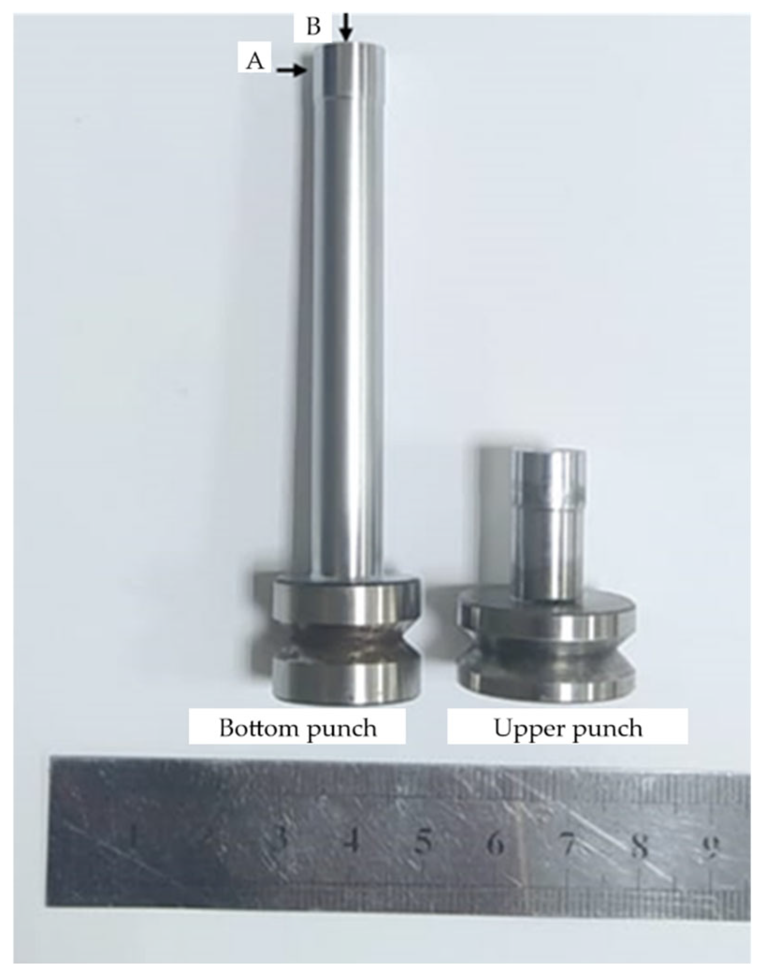
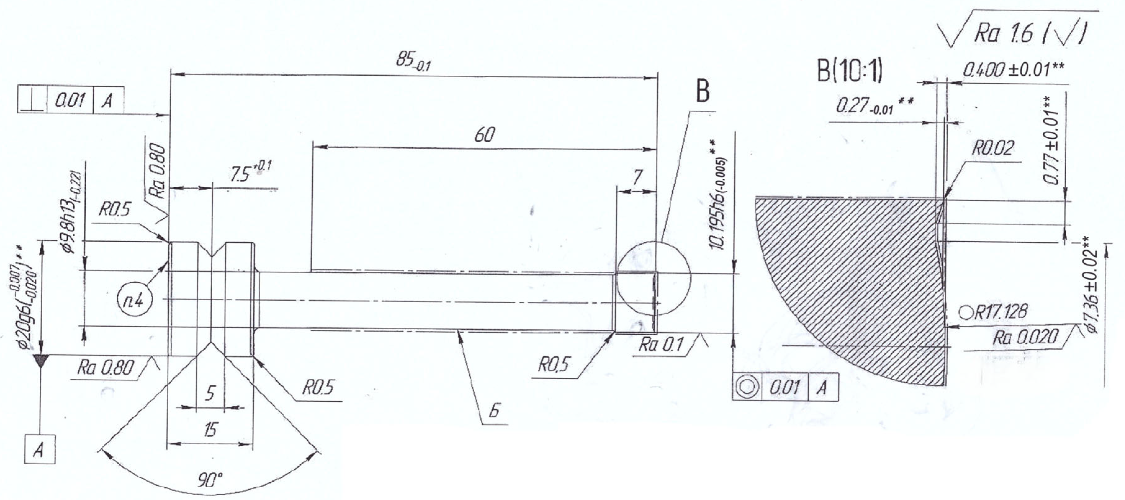
As the material of the study was chosen, the matrix (steel 45) of the press mold as well as the upper and lower punch were coated with Xtv9 (Figure 2) after cyclic loading of nuclear fuel pellets. Steel 45 is a medium carbon structural steel, often used in mechanical engineering for stressed parts. Chemical composition: Carbon (C)—0.45%–0.50%, Silicon (Si)—up to 0.40%, Manganese (Mn)—0.50%–0.80%, Sulfur (S) and Phosphorus (P)—no more than 0.035% in total, Other elements (iron)—up to 100%. Tensile strength—about 600–750 MPa depending on heat treatment. Yield strength is 400–500 MPa. After normalization and hardening, steel 45 has a hardness of about 170–250 HB. Impact toughness: 30–50 J/cm2, which makes the material quite resistant to fracture under impact loads. Figure 3 shows a schematic of the matrix drawing. Examples of studies in which steel 45 was used are given in [11,12,13].
Xtv9 coating is a thermodiffusion coating that is applied to parts subjected to high wear and thermal loads, such as punches and dies in the process of pressing nuclear fuel pellets. Chemical composition: Titanium (Ti) is the main chemical substance that gives the coating high strength. Cobalt (Co) is used to improve heat resistance. Chromium (Cr) improves wear resistance. Nickel (Ni) improves overall corrosion resistance and adhesion of the coating to the substrate. Xtv9 coating is characterized by high hardness, reaching 850–1000 HV (depending on the coating thickness). This allows for significantly improving the wear resistance of molds and punches, which are subjected to prolonged cyclic loading. The coating is able to withstand temperatures up to 800–900 °C, which is important for high temperature applications typical of pressing nuclear fuel pellets. Xtv9 significantly improves the wear resistance of the material, making it ideal for use under cyclic mechanical loading conditions. This coating reduces the number of defects on the surface of the punches and dies, which in turn reduces the likelihood of defects in the pellets themselves. The coating also protects the metal from corrosive substances, which is important when working with nuclear fuel materials that can be chemically active. Examples of work with used Xtv9 [14,15,16,17].

2.2. Research Methods

For the cross-sectional study and coating thickness analysis, the punch was cut using a precision cutting machine to minimize deformation and damage to the structure. Fragments including the working face and side surface (sections A and B) were cast in epoxy resin for ease of further processing. After polymerization of the resin, a standard metallographic preparation procedure was performed, including sequential grinding on abrasive paper and polishing using diamond suspensions to obtain a mirror-like surface.
Metallographic studies were performed to analyze the surface wear, microstructural defects, microcracks and local plastic deformations of the punch. Using a metallographic microscope model Altami MET 5S (Altami, Russia, Moscow), the surface of the sample was photographed at 5 times optical magnification.
For detailed analysis of the morphology of worn surfaces, detection of local defects, mechanical damage and wear fractions, a JEOL JSM-6610LV (JEOL Ltd. Akishima, Tokyo, Japan) scanning electron microscope with energy dispersive analysis at an accelerating voltage of 15 kV was used. There is an example of work with this microscope [18] and also works where many results with SEM are shown [19,20]. To prepare the material for the study, the samples were fixed on a conductive tape. Since the samples under study were on epoxy resin, a conductive carbon layer was applied on them using a Quorum Q150R ES (Quorum technologies Ltd. Ashford, Kent, UK) sputtering machine.
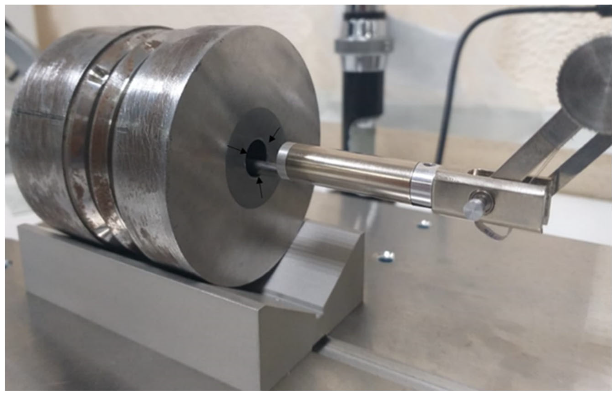
Roughness plays a key role in wear assessment as changes in surface microrelief directly affect press quality and tool life. Roughness was evaluated via the standard method (GOST-2789-73 [21]) using a profilometer model 130. Roughness parameters were used to describe surface microgeometry: Rt—total profile height, Rz—maximum profile height, Ra—average deviation of profile from the center line. The measurement was carried out in 3 places 10 times along the entire length of the matrix circumference with a step—2.669 mm, ϑ = 0.5 mm/s, Rt = 500 µm, L = 15 mm as shown in Figure 4.
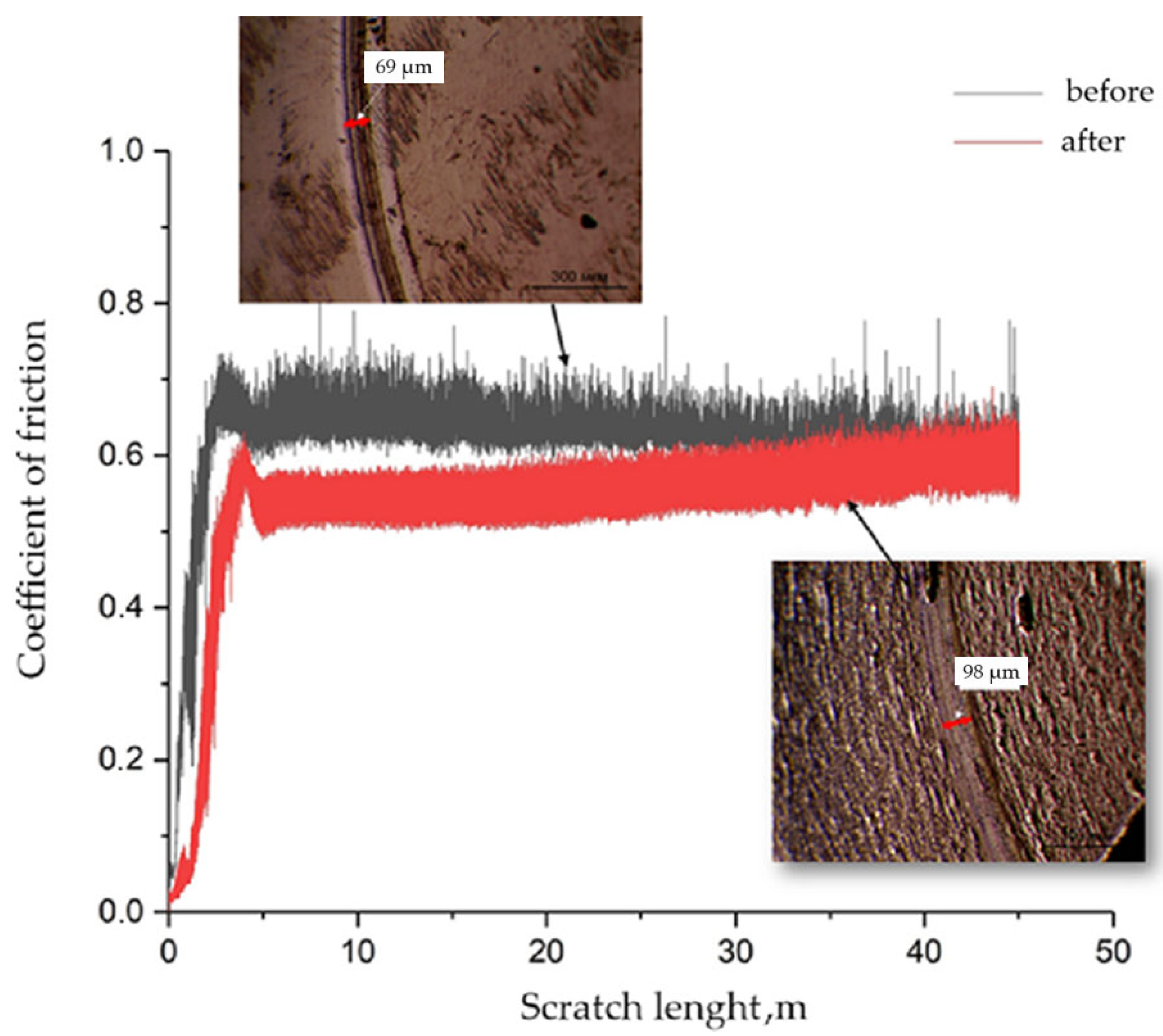
Important information about the fracture mechanism is provided by analyzing the structure of the wear groove (on the sample). Tribological testing. Ball-on-disk tests (Anton Paar TRB3) were performed at room temperature in dry conditions using a 100Cr6 ball (radius 6 mm). The normal load was 2 N; the wear track radius R = 3 mm. The prescribed sliding distance was S = 50 m, corresponding to N ≈ 2653 revolutions (circumference 2πR = 18.85 mm), with a linear speed of v = 30 mm·s−1, giving a test duration of ~1667 s (~27.8 min). The wear scar width/depth were quantified ex situ; the coefficient of friction was recorded in situ. Testing followed ASTM G99/G133 guidance [22].
Further, in order to measure the degree of hardening or softening of the tool material as a result of operation, microhardness measurement was carried out. Vickers microhardness (HV0.05/10) was measured per GOST 9450-76/ISO 6507-1 [23,24] on a METOLAB-502 tester (Metolab, Moskow, Russia): 0.05 kgf load, 10 s dwell. In each zone (A, B), n = 10 indents were made with spacing ≥3d to avoid interaction. Results are reported as mean ± SD (95% CI).
To identify changes in the chemical composition of the working surface and to assess the possible loss of alloying elements, X-ray fluorescence analysis of the surface of the samples was carried out. The research was carried out on the X-ray fluorescence spectrometer S1 TITAN (Bruker, Billerica, MA, USA) (50 kV, 40 µA, Metals mode, 8 mm collimator), based on the use of miniature X-ray tube technology, which is an automated autonomous portable device that provides measurement, information processing, its registration and storage, and is designed to work in laboratory and field conditions. The operating principle of the device is based on the energy dispersive X-ray fluorescence spectral method of analysis. To study the samples we select the mode of metals on the device. We examine each sample by bringing the instrument close to the sample, perpendicular to the sample. Each examination takes 60 s before the instrument signals its completion. In studying the capabilities of this method, the punch before and after operation were selected as objects of study. The measurement was carried out at 3 locations as shown in Figure 5.
In order to determine the phase composition of the sample, XRD patterns were collected on a PANalytical X’Pert Pro (Malvern Panalytical, Almelo, The Netherlands) diffractometer using Cu Kα (λ = 1.5406 Å) operated at 40 kV, 30 mA. Data were acquired over 2θ = 20–90° with a 0.02° step and 1 s counting time per step. Examples of the application of this analysis method are described in detail in [25,26,27].

3. Research Results

3.1. Surface Roughness Analysis

Surface roughness was evaluated using the standard method (GOST 2789-73) with the results displayed on a PC monitor (Figure 4), using a profilometer. As a result of processing the profilograms, the following characteristics of the roughness of the samples were obtained (Table 1).
The conducted studies have shown that the friction surface has sufficient cleanliness and is characterized by wear of traces of damage, in section (B) of contact interaction, arising in the given conditions of friction, localized in thin surface layers annihilate in the process of cyclic loading.
To increase the informativeness of the study we noted several parameters, such as Rq as the mean square deviation of the profile and Rv is the depth of the largest depression of the profile, but the main parameter was Ra.
The analysis of the table shows that as a result of working out of the inner holes of the matrix for pressing, Ra is the average deviation of the profile from the middle line, increased 3 times from the initial value of the roughness of the matrix (Table 1). Roughness of surfaces after running-in indicates the formation of microgeometry, explained by significant wear, the inner hole of the matrix.
Table 2 shows the profilograms of the punch surface before and after pressing of uranium dioxide tablets. The measurement was carried out at two locations (A and B).
After pressing under real shop conditions, the surface profile changes. The roughness of the surface increases and its wear occurs. Also the working surface in zone B is worn, which negatively affects its performance characteristics.

3.2. Microhardness

The obtained results showed a decrease in microhardness at the working areas by 25%–30%, which indicates the degradation of the structure of the protective coating and local accumulation of damage in the surface layers of steel. Before operation, the microhardness averaged 875 HV, while after long-term operation—635 HV. The most pronounced decrease was observed in the zone of active contact with press powder (section B), which correlates with the results of visual observations and profilometric data. The observed decrease in microhardness indicates the beginning of wear and fatigue processes of the tool material. In particular, the accumulation of plastic deformations, the formation of microcracks and the destruction of the protective layer significantly weaken the ability of the surface to resist contact loads. In this paper [28] it is stated that a decrease in surface microhardness is an early sign of fatigue degradation of mold surfaces used in pressing nuclear fuel. This pattern is confirmed in the present work (Figure 6).

3.3. Analysis of Tribological Tests

The results of tribological tests of the sample at room temperature are shown in Figure 7. All of them had a consistently low coefficient of friction and a short run-in period (>5 m), the one tested paired with a 100Cr6 ball had a friction path of 50 m and a stable coefficient of friction. Evaluating the wear resistance of the specimens based on the geometric parameters of the wear groove, it can be said that the width of the groove of the specimen after operation is significantly larger compared to the original specimen.
After operation, visible pores are observed on the surface, indicating surface wear of the sample. Measurement of the coefficient of friction showed an increase of 20% after operation, indicating deterioration of the antifriction properties of the punch surface. The wear depth increased, which confirms the high tool loading during pressing.

3.4. Xrf (X-Ray Fluorescence) Results

The results of X-ray fluorescence analysis showed the change in elemental composition of different sections of the punch before and after operation (Table 3). At section “B” after operation, an increased iron content was recorded due to wear of Xtv9 coatings. A comparatively small change in the elemental composition is observed at the site “A”.
A decrease in the concentration of alloying elements such as chromium and molybdenum was recorded, indicating leaching of the protective layer and loss of corrosion resistance. Surfaces subjected to prolonged contact with uranium dioxide powder showed accumulation of oxide compounds, which is confirmed by an increase in the intensity of oxygen and uranium lines in the spectra.

3.5. X-Ray Phase Analysis (XRD—X-Ray Diffraction)

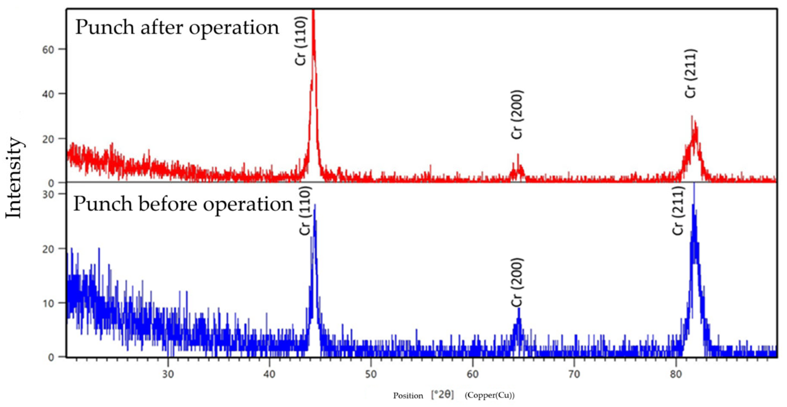
X-ray phase analysis (XRD) of the samples showed pronounced changes in the condition of the punch surface layer before and after operation. Intense peaks corresponding to chromium-containing phases were registered on the diffractograms of the new tool, which confirms the presence of a protective coating. After operation, broadening of diffraction lines and decrease in their intensity were observed, which indicates accumulation of defects in the crystal lattice, internal stress and possible amorphization of a part of the surface layer (Figure 8).
In addition, the appearance of additional weak peaks corresponding to oxide phases (e.g., Cr2O3) indicates oxidation of the surface under friction and temperature stresses. As emphasized in [26]:
“X-ray diffraction provides critical insight into residual stresses and defect accumulation in surface-engineered components, often preceding visible wear damage”. This is consistent with the results of SEM and XRF analysis, which showed evidence of coating failure and exposure of the underlying metallic material of the punch.

3.6. Results of M Croscopic Analysis

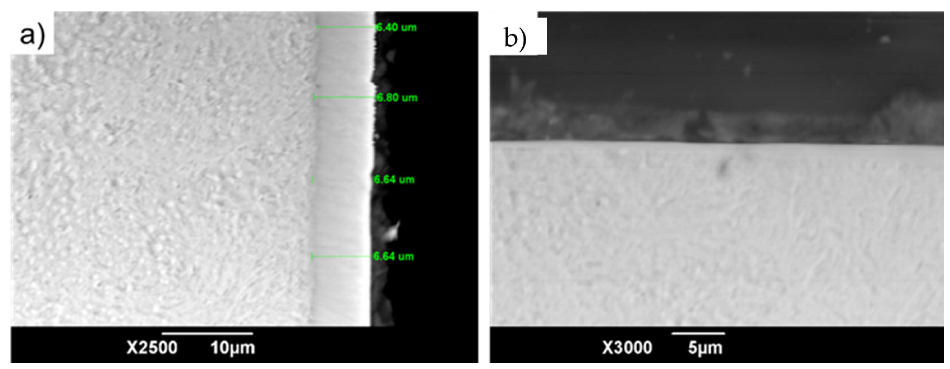
Figure 9 shows the SEM image of the cross-section of the punch. The results of the study confirm the results of the XRF analysis. The examination showed the absence of Xtv9 coating at section “B” (Figure 10B). At site “A” the thickness of the layer was ~ 6.50 μm (Figure 10A).
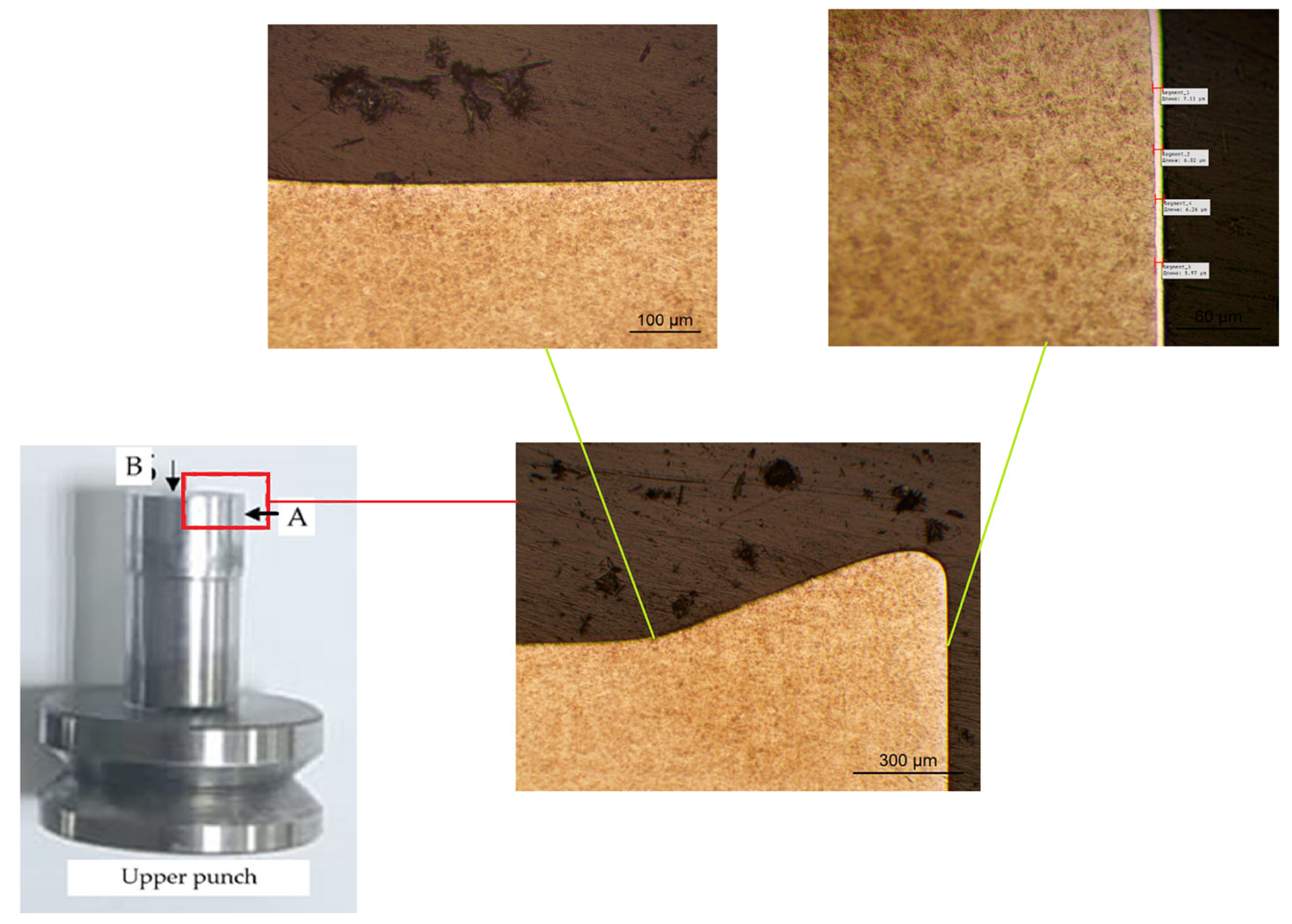
Optical image of the punch cross-section (Figure 11) Metallographic analysis of the cross-section of the working edge of the top punch after operation, showing different wear mechanisms. Enlarged slice (A) shows the side surface subjected to frictional and abrasive wear from contact with the die. Figure 10B illustrates the area of the working face and edge where the most intense failure has occurred, including degradation of the protective coating and base material, resulting from complex impact-abrasion and fatigue wear.
Figure 11 shows the distribution of elements across the cross-section of the punch at section “B”. The EDS data indicate a thin layer of Xtv9 coatings. The concentration of chromium in the coating is 3.3–3.8 weight, %.
The SEM image of the cross-section of the original punch (before operation) shows (Figure 12) that the chrome layer has a thickness of ~6.50 µm and is characterized by a dense structure. Based on the analysis of the elemental composition of the surface, it can be said that the wear of the punch occurs in sections “A” and “B”.
Elemental analysis was performed for five sections (points) of the punch surface after operation. Figure 13 shows microphotographs of the surface and elemental analysis data of the punch (Table 4), indicating a satisfactory match of the composition with the chrome plated coating.
Analysis of worn areas of molds and punches using SEM showed the presence of mechanical damage to the surface. Zones of plastic deformation, microcracks and areas of adhesive material transfer were identified. It was found that in the areas of contact with uranium dioxide powder there is localized destruction of the coating with the formation of micro-defects, which contributes to further wear progression. As emphasized in the study “Scanning electron microscopy revealed extensive microstructural damage, including crack propagation and material transfer, which are indicative of combined adhesive-abrasive wear mechanisms under cyclic loading conditions”. At ×5000 magnification, fine wear particles were detected, indicative of a combined abrasive and adhesive wear mechanism. Areas with oxide phase layering were also observed, which is confirmed by X-ray fluorescence analysis data.

4. Discussion

The study confirmed that press tool wear during UO2 tablet molding is manifested through complex degradation mechanisms involving both abrasive and adhesive wear. The decrease in microhardness detected in the active contact zone indicates the accumulation of plastic deformations and destruction of the protective layer of the Xtv9 coating. These changes correlate with the growth of roughness on the tool surface, which is established by profilometric analysis, and indicate the impact of high cyclic loads and temperatures.
X-ray fluorescence analysis data demonstrate the loss of alloying elements (Cr, Mo) in the contact zone, which is associated with the destruction of the surface layer and partial diffusion as a result of friction. X-ray phase analysis showed a decrease in the intensity and broadening of diffraction peaks, indicating the formation of defective sites and internal stresses in the crystal lattice. The appearance of oxide phases (Cr2O3) on the surface additionally confirms thermo-oxidative degradation of the coating under operating conditions.
SEM analysis allowed for visualizing microcracks, zones of plastic deformation, traces of abrasive interaction and material transfer. There were also recorded signs of local destruction of chrome coating and formation of micro voids, which reduces the efficiency of tool operation and increases the probability of defective products. The totality of the observed defects indicates a combined wear mechanism, where both mechanical and chemical–temperature factors play a role.
These data support the need to optimize pressing parameters, tool and coating material selection and technical inspection regulations. The proposed evaluation methods (XRF, XRD, SEM, microhardness, profilometry) have demonstrated high efficiency for comprehensive tool condition analysis.

5. Conclusions

A multi-modal analysis of die/punch wear in UO2 pellet pressing shows a combined abrasive–adhesive wear mechanism accompanied by microcrack formation and localized coating degradation. Quantitatively, the microhardness drops from 875 to 635 HV (−27.4%) in the active contact zone, while surface roughness increases (matrix Ra ≈ 0.058 → 0.172 µm, ≈3×; punch Ra increases by 51%–133% depending on location). Tribometry (2 N, R = 3 mm, 50 m sliding) indicates a ~20% rise in the coefficient of friction after service. XRF confirms chromium depletion and iron exposure in worn regions, whereas XRD reveals peak broadening and weak oxide reflections (e.g., Cr2O3), consistent with defect accumulation and thermo-oxidative degradation.
The proposed methods of analysis can be used in industrial conditions to assess the residual life of press tools and to develop recommendations for their restoration or replacement. Further research should be directed to the study of alternative coatings resistant to radiation-temperature loading, as well as to the introduction of intelligent systems for real-time tool condition monitoring.

Author Contributions

Conceptualization, B.R.; Methodology, A.K. (Aidar Kengesbekov) and M.K.; Formal analysis, N.M.; Investigation, N.M., A.K. (Aidar Kengesbekov) and A.K. (Arystanbek Kussainov); Writing—original draft, N.M. and A.K. (Aidar Kengesbekov); Writing—review & editing, B.R. and M.K.; Visualization, A.K. (Aidar Kengesbekov) and A.K. (Arystanbek Kussainov); Supervision, B.R.; Project administration, B.R. All authors have read and agreed to the published version of the manuscript.

Funding

This research has been funded by the Committee of Science of the Ministry of Science and Higher Education of the Republic of Kazakhstan (Grant No. BR24992854).

Institutional Review Board Statement

Not applicable.

Informed Consent Statement

Informed consent was obtained from all the subjects involved in this study.

Data Availability Statement

Data are contained within the article.

Conflicts of Interest

Authors Bauyrzhan Rakhadilov, Nurtoleu Magazov, Aidar Kengesbekov and Arystanbek Kussainov were employed by the company Plasma Science LLP. Author Manarbek Kylyshkanov was employed by the company Ulba Metallurgical Plant JSC.

References

  1. Santra, N. Advances in Process Materials for Production of UO2. 2021. Available online: https://www.academia.edu/56709344/Advances_in_Process_Materials_for_Production_of_Uo (accessed on 19 August 2025).
  2. Jeon, S.-C.; Lee, J.-W.; Lee, J.-H.; Kang, S.-J.; Lee, K.-Y.; Cho, Y.-Z.; Ahn, D.-H.; Song, K.-C. Fabrication of UO2 Porous Pellets on a Scale of 30 kg-U/Batch at the PRIDE Facility. Adv. Mater. Sci. Eng. 2015, 2015, 376173. [Google Scholar] [CrossRef]
  3. Tyrpekl, V.; Cologna, M.; Vigier, J.-F.; Cambriani, A.; De Weerd, W.; Somers, J. Preparation of bulk-nanostructured UO2 pellets using high-pressure spark plasma sintering for LWR fuel safety assessment. J. Am. Ceram. Soc. 2017, 100, 1269–1274. [Google Scholar] [CrossRef]
  4. Li, B.; Yang, Z.; Wang, Z.; Huang, Q.; Zhang, D.; Xu, Q.; Xie, L.; Zhong, Y.; Wang, Y.; Duan, L.; et al. Thermal conductivity of UO2 pellets enhanced by a semi-continuous structure of Ti3SiC2. Ceram. Int. 2023, 49, 26049–26056. [Google Scholar] [CrossRef]
  5. Gorton, J.P.; McDuffee, J.L.; Snarr, P.L.; Petrie, C.M.; Nelson, A.T. Heat transfer optimization of uo2-mo fuel using genetic algorithms. Nucl. Eng. Des. 2024, 418, 112861. [Google Scholar] [CrossRef]
  6. Fu, J.; Li, J.; Wang, Z.; Cong, T.; Guo, H.; Xiao, Y.; Gu, H. Numerical study of the effect of helical fuel rod geometry on single-phase flow and heat transfer characteristics. Ann. Nucl. Energy 2024, 205, 110574. [Google Scholar] [CrossRef]
  7. Sedgi, I.; Moyal, A.; Assulin, M.; Rubinstein, A.; Brandis, M.; Gershinsky, G.; Edry, I.; Halevy, I.; Fruchter, N.; Zakon, Y.; et al. Nuclear forensic signatures of UO2 fuel pellets for differentiation and provenance determination illustrated using synthetic database. J. Nucl. Mater. 2023, 587, 154730. [Google Scholar] [CrossRef]
  8. Dooley, P.; Contryman, D.; Hervey, A.; Ivers, R.; Reddish, I.; Song, Y. Design of an optimized nuclear fuel pellet. Nucl. Sci. Technol. Open Res. 2024, 2, 1. [Google Scholar] [CrossRef]
  9. Rakhadilov, B.K.; Kurbanbekov, S.R.; Kilishkhanov, M.K.; Kenesbekov, A.B.; Amanzholov, S. Changing the structure and phasestates and the microhardness of the R6M5 steel surface layer after electrolytic-plasma nitriding. Eurasian J. Phys. Funct. Mater. 2018, 2, 259–266. [Google Scholar] [CrossRef]
  10. Balboa, H.; Van Brutzel, L.; Chartier, A.; Le Bouar, Y. Assessment of empirical potential for MOX nuclear fuels and thermomechanical properties. J. Nucl. Mater. 2017, 495, 67–77. [Google Scholar] [CrossRef]
  11. Cheng, J.; Zhao, J.-H.; Zhang, J.-Y.; Guo, Y.; He, K.; Shang-guan, J.-J.; Wen, F.-L. Microstructure and Mechanical Properties of Galvanized-45 Steel/AZ91D Bimetallic Material by Liquid-Solid Compound Casting. Materials 2019, 12, 1651. [Google Scholar] [CrossRef]
  12. Bai, X.; Jiang, J.; Li, C.H.; Dong, L.; Duan, Z.; Zhang, H. Lubrication Performance of Different Concentrations of Al2O3 Nanofluids on Minimum Quantity Lubrication Milling. Res. Sq. 2021. [Google Scholar] [CrossRef]
  13. Rakhadilov, B.; Kengesbekov, A.; Zhurerova, L.; Kozhanova, R.; Sagdoldina, Z. Impact of electronic radiation on the morphology of the fine structure of the surface layer of R6M5 steel. Machines 2021, 9, 24. [Google Scholar] [CrossRef]
  14. El-Atwani, O.; Kim, H.; Gigax, J.G.; Harvey, C.; Aytuna, B.; Efe, M.; Maloy, S.A. Stable, Ductile and Strong Ultrafine HT-9 Steels via Large Strain Machining. Nanomaterials 2021, 11, 2538. [Google Scholar] [CrossRef]
  15. Chen, Y. Irradiation Effects Of Ht-9 Martensitic Steel. Nucl. Eng. Technol. 2013, 45, 311–322. [Google Scholar] [CrossRef]
  16. Sprouster, D.J.; Adam, B.; Koziol, A.; Rolly, L.; Huotilainen, C.; Tucker, J.D. Long-term thermal aging effects in ferritic-martensitic steel HT9. Mater. Charact. 2024, 217, 114418. [Google Scholar] [CrossRef]
  17. Byun, T.S.; Collins, D.A.; Lach, T.G.; Choi, J.P.; Maloy, S.A. Thermomechanical Processing for Improved Mechanical Properties of HT9 Steels. Materials 2024, 17, 3803. [Google Scholar] [CrossRef] [PubMed]
  18. Kengesbekov, A.; Rakhadilov, B.; Satbaeva, Z.; Kambarov, Y. Effect of Helium Plasma Irradiation on Microstructures and Mechanical Properties of Tungsten. Adv. Mater. Sci. Eng. 2024, 2024, 1968615. [Google Scholar] [CrossRef]
  19. Kengesbekov, A. Influence of Plasma Arc Current and Gas Flow on the Structural and Tribological Properties of TiN Coatings Obtained by Plasma Spraying. Coatings 2024, 14, 1404. [Google Scholar] [CrossRef]
  20. Xie, Z.; Yin, C.; Zhang, J.; Jiao, Y.; Ding, G.; Yang, Q.; Ding, S.; Chen, P. On the creep mechanisms and macroscopic creep rate modeling of high-uranium-density composite fuels. J. Nucl. Mater. 2023, 586, 154679. [Google Scholar] [CrossRef]
  21. GOST-2789-73; Surface Roughness. Parameters and Characteristics. In Consulting: Ukraine, Russia, 2006.
  22. ASTM G99/G133-22; Standard Test Method for Linearly Reciprocating Ball-on-Flat Sliding Wear. ASTM: West Conshohocken, PA, USA, 2022.
  23. GOST 9450-76; Measurement of Microhardness by Indentation of Diamond Tips. In Consulting: Ukraine, Russia, 1977.
  24. ISO 6507-1:2023; Metallic Materials—Vickers Hardness Test. Part 1: Test method. ISO: Geneva, Switzerland, 2023.
  25. Kolyvanov, E.L.; Afonikova, N.S.; Kobelev, N.P. X-ray Diffraction Tests of Near-Surface Layer of Copper Treated by Ball Rolling. Inorg. Mater. Appl. Res. 2018, 9, 699–702. [Google Scholar] [CrossRef]
  26. Harrington, G.F.; Santiso, J. Back-to-Basics tutorial: X-ray diffraction of thin films. J. Electroceram. 2021, 47, 141–163. [Google Scholar] [CrossRef]
  27. Rizal, C. Microstructure, Surface Plasmon, Magneto-optic Surface Plasmon, and Sensitivity Properties of Magneto-plasmonic Co/Au Multilayers. IEEE Trans. Magn. 2018, 54, 5300309. [Google Scholar] [CrossRef]
  28. Bai, X.; Jiang, J.; Li, C.; Dong, L.; Ali, H.M.; Sharma, S. Tribological Performance of Different Concentrations of Al2O3 Nanofluids on Minimum Quantity Lubrication Milling. Chin. J. Mech. Eng. 2023, 36, 11. [Google Scholar] [CrossRef]
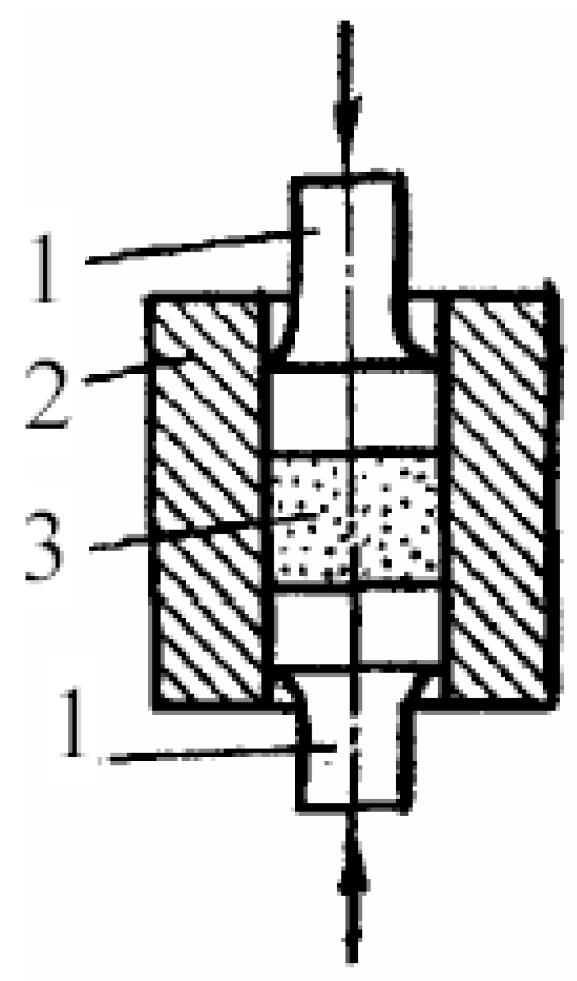
Figure 1. Scheme of double-sided pressing 1—Punches, 2—Mold, 3—Press powder.
Coatings 15 01088 g001
Figure 2. Punch coated with Xtv9 working face (A) and side surface (B).
Coatings 15 01088 g002
Figure 3. Schematic drawing of poisson lower. ** marks critical, tightly-toleranced dimensions.
Coatings 15 01088 g003
Figure 4. The process of matrix examination on the profilometer.
Coatings 15 01088 g004
Figure 5. Top punch working face (A), side surface (B) and not working surface (C).
Coatings 15 01088 g005
Figure 6. Microhardness of the samples.
Coatings 15 01088 g006
Figure 7. Tribological tests of the punch before and after operation.
Coatings 15 01088 g007
Figure 8. Diffractogram.
Coatings 15 01088 g008
Figure 9. SEM image of the cross-section of the punch. (a) Section A; (b) section B.
Coatings 15 01088 g009
Figure 10. Optical image of the punch cross-section working face (B) and side surface (A).
Coatings 15 01088 g010
Figure 11. SEM image of the cross punch of section “B”.
Coatings 15 01088 g011
Figure 12. SEM image of the cross punch before operation.
Coatings 15 01088 g012
Figure 13. SEM image of cross punch.
Coatings 15 01088 g013
Table 1. Results of evaluation of roughness of the inner hole of the surface matrix.
SampleProfile Along the Punch LengthParameters, Microns
Matrix before operationCoatings 15 01088 i001Ra = 0.0559
Rz = 0.125
Rq = 0.0779
Rv = 0.119
Coatings 15 01088 i002Ra = 0.0623
Rz = 0.143
Rq = 0.0881
Rv = 0.125
Coatings 15 01088 i003Ra = 0.0573
Rz = 0.131
Rq = 0.0837
Rv = 0.125
Matrix after operationCoatings 15 01088 i004Ra = 0.150
Rz = 0.474
Rq = 0.212
Rv = 0.354
Coatings 15 01088 i005Ra = 0.206
Rz = 0.549
Rq = 0.261
Rv = 0.455
Coatings 15 01088 i006Ra = 0.161
Rz = 0.493
Rq = 0.234
Rv = 0.395
Table 2. Results of punch roughness evaluation.
SamplePunch Length ProfileParameters, Microns
Punch before operation (side A)Coatings 15 01088 i007Ra = 0.140
Rz = 1.11
Rt = 1.62
Rq = 0.192
Rv = 0.659
Punch after operation, (side A)Coatings 15 01088 i008Ra = 0.212
Rz = 1.21
Rt = 1.75
Rq = 0.285
Rv = 0.772
Punch before operation (side B)Coatings 15 01088 i009Ra = 0.158
Rz = 0.914
Rt = 9.96
Rq = 0.243
Rv = 0.586
Punch after operation (side B)Coatings 15 01088 i010Ra = 0.368
Rz = 2.23
Rt = 4.42
Rq = 0.529
Rv = 0.937
Table 3. Results of analysis of elemental composition of the sample.
Punch


Punch Before Operation
(Side B)
Punch After Operation
(Side B)
Punch Before Operation
(Side A)
Punch After
Operation
(Side A)
Element%%%+/−[×]%+/−[×]%+/−[×]
Fe60.140481.131381.13130.617026.77150.617039.47920.7736
Cr38.423417.775817.77580.662671.74050.662658.72490.6478
Co1.17870.70740.70740.16231.18370.16231.24830.1922
As0.15160.25010.25010.05480.07290.05480.16860.0890
Cu0.07020.09810.09810.01900.03950.01900.04160.0236
Mo0.01560.01730.01730.00900.01480.00900.004730.00135
Au---0.04500.10170.0450--
V---0.04430.04700.04430.22460.0641
Ni--------
Zn-0.00410.0041-----
Table 4. Results of analysis of elemental composition of sample.
SpectrumIn Stat.OCrFeTotal
Spectrum 1Yes4.5494.710.75100.00
Spectrum 2Yes5.2894.210.51100.00
Spectrum 3Yes2.7996.171.05100.00
Spectrum 4Yes2.9195.741.36100.00
Spectrum 5Yes3.3095.770.93100.00
Average 3.7695.320.92100.00
Standard deviation 1.100.820.32
Max. 5.2896.171.36
Min. 2.7994.210.51
Disclaimer/Publisher’s Note: The statements, opinions and data contained in all publications are solely those of the individual author(s) and contributor(s) and not of MDPI and/or the editor(s). MDPI and/or the editor(s) disclaim responsibility for any injury to people or property resulting from any ideas, methods, instructions or products referred to in the content.