Article

Study on the Influence of Heat Input on Microstructure and Properties of Q420C Steel Welded Joints

1
Nanjing University of Science and Technology, Nanjing 210094, China
2
Guangzhou Shipyard International Co., Ltd., Guangzhou 511462, China
3
Yantai University, Yantai 264005, China
*
Authors to whom correspondence should be addressed.
Coatings 2025, 15(8), 957; https://doi.org/10.3390/coatings15080957 (registering DOI)
Submission received: 23 July 2025 / Revised: 9 August 2025 / Accepted: 14 August 2025 / Published: 16 August 2025
(This article belongs to the Section Surface Characterization, Deposition and Modification)

Abstract

The occurrence of the welding heat-affected zone in Q420C steel may lead to a reduction in the toughness of the welded joint and disruption of high strength-toughness combination of Q420C. This study investigates the microstructure and mechanical properties of Q420C steel welded joints under three heat in-puts of 25 kJ/cm, 100 kJ/cm, 200 kJ/cm, and 300 kJ/cm, with high-strength matching adopted for the welded joints, Charpy impact tests at 0 °C, −20 °C, and −40 °C were conducted on the weld metal, fusion line(FL), and heat-affected zone (HAZ). The weld metal maintains high impact toughness across all tested temperatures. However, increasing the heat input leads to coarsening of the microstructure in the overheated zone of the HAZ, accompanied by the formation of ferrite. At a heat input of 300 kJ/cm, significant amounts of coarse intergranular ferrite and intragranular blocky ferrite develop in the overheated zone. These microstructural changes result in a marked reduction in the impact toughness of both the fusion zone and HAZ, and the fracture mode shifts from ductile to cleavage fracture. To ensure adequate impact toughness of Q420C welded joints, the welding heat input should be kept below 200 kJ/cm.

1. Introduction

With the development of technology, more and more high-strength steel structures have been used in various circumstances due to its remarkable strength-to-density ratio [1,2,3,4]. For instance, Q420 high strength steel with the nominal yield strength of 420 MPa has been used in the transmission line engineer in China [5].
Q420 steel is a low-alloy high-strength-structural teel produced in China through a microalloying and hot mechanical rolling process. It has high comprehensive mechanical properties and is mainly used in transmission towers, offshore platform, oil derricks, and coal mine steel structural supports [5]. For example, with an offshore platform structure, fatigue failure of the structure can easily occur under long-term repeated wave loads. The fatigue failure of the steel and its joints has become the focus of structural engineers [6].
Welding, as one of the basic methods for joining steel, has also become one of the key manufacturing technologies for steel structures. The combination of high strength and high toughness is jeopardized during the welding thermal cycle process because the heat-affected zone, which is created by fast heating and prolonged exposure to high temperatures, shows decreased toughness [7]. The studies found that the coarse-grained heat affected zone (CGHAZ) close to the fusion line experiences significant grain growth due to peak temperatures as high as 1350 °C or higher, which is therefore considered the region with the poorest toughness [8].
For Q420 steel, current research mainly focuses on the corrosion resistance and mechanical properties of the steel itself [3,5,9,10]. Some researchers studied the Influence of welding structure forms on performance [11,12]. In terms of welding, there are only a few simple studies on welding processes in China [13]. Systematic research on the influence of welding processes, especially welding heat input, on the performance of welded joints is still lacking.
This study taken Q420C steel as the research object, used different welding methods and heat inputs to weld Q420C steel, and analyzed and revealed the influence of heat input on the microstructure and mechanical properties of the welding joints.

2. Materials and Methods

The materials used in this study were Q420C steel with a thickness of 40 mm. According to the requirements of Chinese standard GB/T 1591 [14], the mechanical properties of Q420C are shown in Table 1. Table 2 shows the chemical composition of Q420C.
The study adopted three welding methods, namely flux-cored wire CO2 gas shielded welding (FCAW), flux asbest baking+single-wire submerged arc welding (FAB + SAW), and electrogas welding (EGW), with corresponding heat inputs of 25 kJ/cm (Low heat input, LHI), 100 kJ/cm (Medium heat input, MHI), 200 kJ/cm (Medium high heat input, MHHI and 300 kJ/cm (High heat input, HHI), respectively. The formula for calculating the welding heat input Q is: Q = UI/v, where U is the welding voltage, I is the welding current, and v is the welding speed. For multi-pass welding, the welding parameters of each fill pass and each cover pass are the same, and the heat input refers to the heat input of each pass. The wire used in FCAW is GFR-81K2 with a diameter of 1.2 mm. The wire used in FAB+SAW is H-14 with a diameter of 4.8 mm, and the flux grade is S-707T. The wire used in EGW is SC-EG3 with a diameter of 1.6 mm.
The groove forms and bead distributions adopted by the three welding methods are shown in Figure 1a–c, respectively.
After welding, the quality of the welded joints was inspected by ultrasonic non-destructive testing. Cross-sectional specimens were cut, polished, and etched with 4% nitric acid alcohol to observe the macroscopic morphologies of the joints. Metallographic specimens were cut from different regions of the welded joint, ground, and polished, then etched with 4% nitric acid alcohol to observe the microstructure of the welds and heat-affected zones with optical microscope (OM, LEICADM-2500M, Carl Zeiss AG, Baden-Württemberg, Germany) and scanning electron microscope (SEM, JSM-IT200LA, JEOL, Akishima-shi, Tokyo, Japan). The accelerating voltage used was 20 kV. Tensile properties and impact tests at 0 °C, −20 °C, and −40 °C were conducted on the welded joints in accordance with the Materials and Welding Specifications of China Classification Society (2024) (Beijing, China). Impact specimens were sampled from the surface, with impact notches located at the weld metal, fusion line (FL0), 2 mm outside the fusion line (FL2), and 5 mm outside the fusion line (FL5). After the impact tests, the impact fracture surfaces were observed using a scanning electron microscope. The impact-fractured specimens were cut perpendicular to the impact notch, ground, and polished to observe the morphology of the fracture cross-section and the adjacent area with optical microscope and scanning electron microscope.

3. Results

3.1. Macroscopic Morphologies

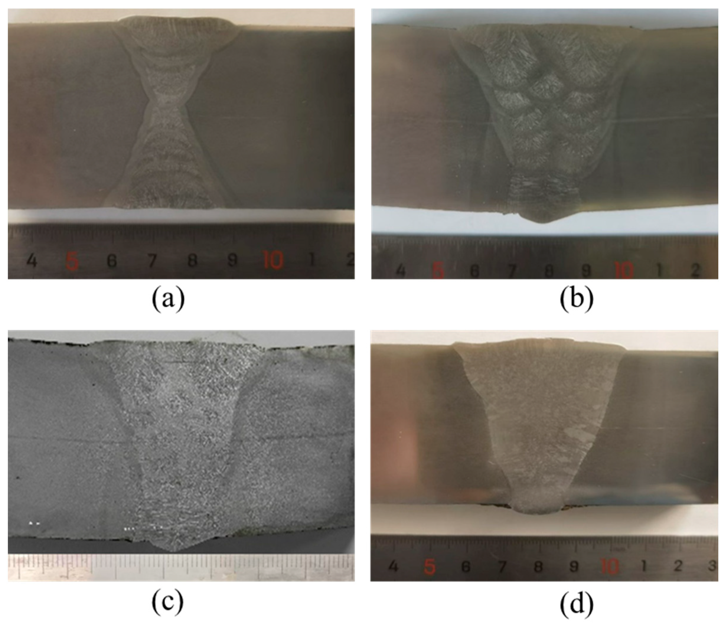
Figure 2 shows the macroscopic morphology of the welded joints under three different heat inputs. It can be observed that the welds are well-formed without defects such as lack of fusion. All three welding methods can ensure good forming quality. In fact, the results of ultrasonic non-destructive testing also show that there are no defects inside the weld.

3.2. Microstructures

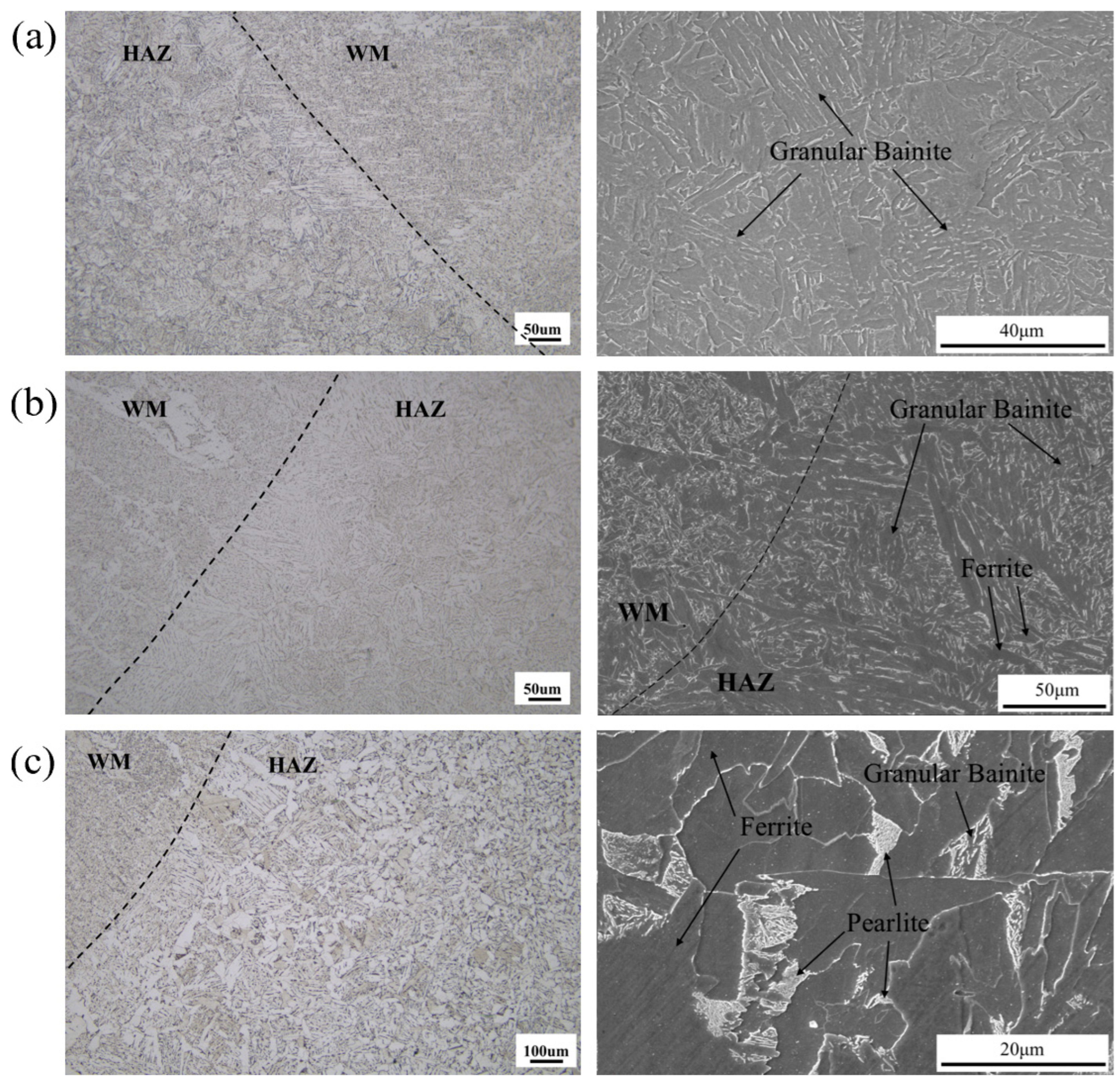
Figure 3 shows the microstructures of the welded joints under different heat inputs. It can be seen that although different welding wires were used, the microstructures of the welds are similar under the three heat inputs, which are mainly composed of acicular ferrite and blocky ferrite. With the change of heat input, the microstructure of HAZ has changed significantly. When the heat inputs are 25 kJ/cm and 200 kJ/cm, the microstructure of the overheated zone is mainly granular bainite. As can be seen from Figure 3a,b, when the heat input increases, the average size of bainite lath bundles also increases due to the increase in the size of primary austenite grains. In addition, when the heat input increases to 200 kJ/cm, a small amount of blocky ferrite is formed in the overheated zone.
When the heat input increases to 300 kJ/cm, the microstructure of the overheated zone changes significantly. As shown in Figure 3c, a large number of long strip-shaped ferrite was generated along the primary austenite grain boundary of the overheated zone. Inside the primary austenite, in addition to granular bainite, a large amount of blocky ferrite and a small amount of pearlite were also formed.
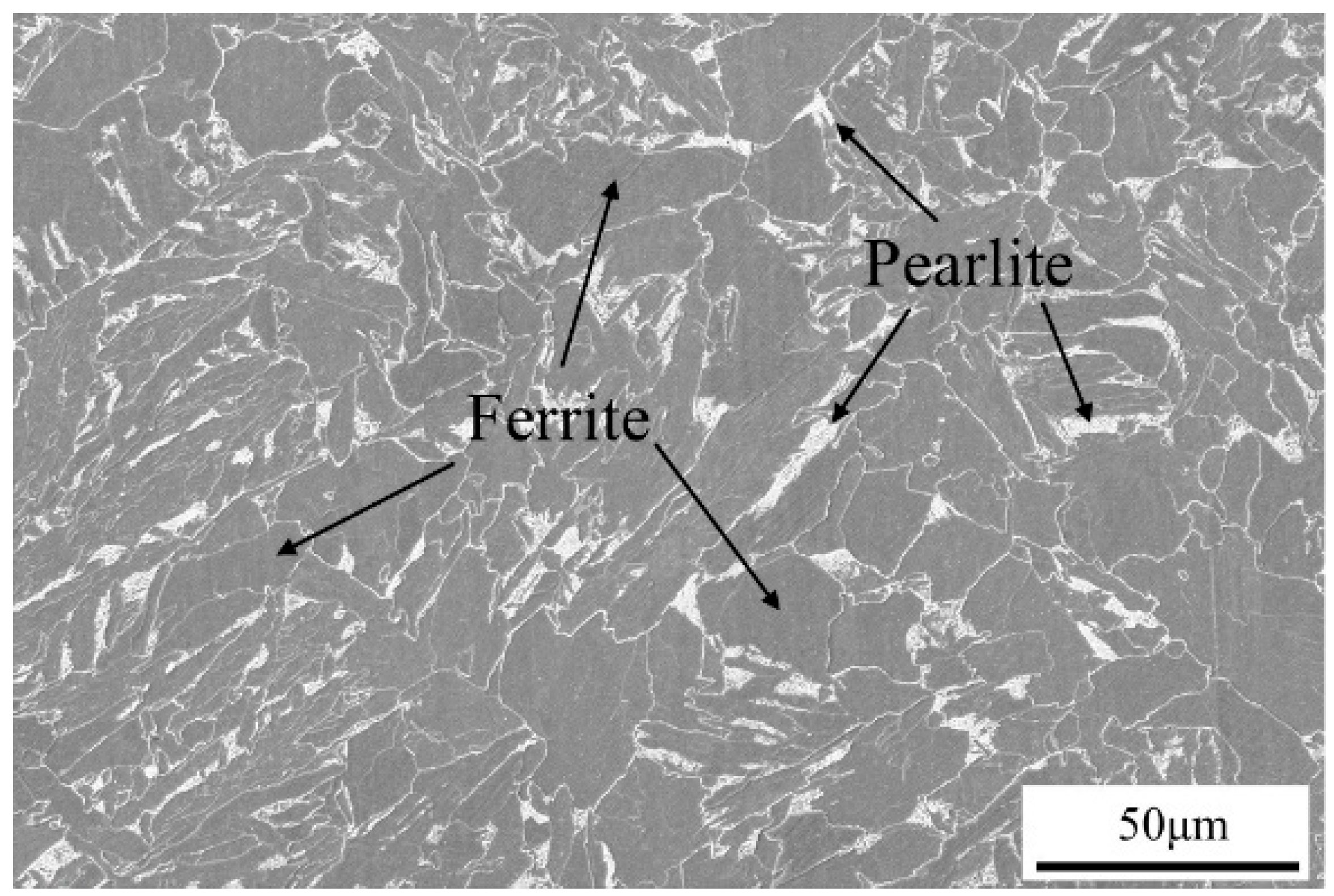
Figure 4 shows the microstructure of the normalized zone under 300 kJ/cm. It can be seen that due to the relatively lower peak temperature in the normalized zone than that in the overheated zone, the structure of the normalized zone is significantly smaller than that of the overheated zone. In addition, because the cooling rate was relatively lower than that in the overheated zone, the number of granular bainite in the normalized zone is significantly reduced, and its structure is mainly composed of ferrite and pearlite.
From the analysis of the relationship between the microstructure and heat input, it can be concluded that when the heat input increases, the cooling rate of HAZ in Q420C steel decreases, and the microstructure type transforms from granular bainite to ferrite and pearlite.

3.3. Mechanical Properties

Due to the adoption of high-strength matching, the tensile specimens all fractured in the base metal under the three heat inputs, with tensile strengths of 552 MPa, 548 MPa, and 534 MPa, respectively, meeting the standard requirements.
In terms of impact properties, although the welding wires used under the three heat inputs were different, the impact toughness of the welds all meets the requirements of the standard. When the heat input changes, the difference in the impact toughness of the joint is mainly reflected in the fusion line and the heat-affected zone.
The impact test results of welded joints tested at different temperatures are shown in Figure 5. It can be seen that under low welding heat input and middle heat input conditions, the impact energy of the fusion line is smaller than that of the HAZ, with the highest impact energy occurring at a distance of about 5 mm from the fusion line; However, under high heat input conditions, the impact energy in the HAZ is smaller than that in the fusion line area.
When the heat input is 25 kJ/cm, the impact toughness of both the fusion line and HAZ is relatively high. The impact absorbed energy of the fusion line at different test temperatures ranges from 135 J to 156 J, and that of the HAZ exceeds 200 J. It should be noted that although the V-notch is located in the fusion line, the crack will inevitably propagate through the heat-affected zone during propagation. When the notch is in the heat-affected zone, due to the low heat input, the width of the heat-affected zone is relatively narrow, so the crack will pass through the base metal during impact. Moreover, the base metal has finer microstructure with a large number of high-angle grain boundaries, which can hinder crack propagation. Therefore, the impact absorbed energy of the heat-affected zone is higher than that of the fusion zone.
When the heat input increases to 200 kJ/cm, the impact absorbed energy of HAZ remains above 196 J, but the impact absorbed energy of the fusion line decreases significantly. At the test temperature of −20 °C, the average impact absorbed energy of the fusion zone drops to 120 J, and at −40 °C, it sharply decreases to 70 J. Similar to the case with the heat input of 25 kJ/cm, when the heat input is 200 kJ/cm, the reason for the decrease in impact absorption energy in the fusion zone is related to the regions through which the crack propagates. When the V-notch is located at the fusion line, the crack will pass through HAZ with coarse microstructure during propagation, resulting in a decrease in impact absorption energy. When the V-notch is located in HAZ, however, the crack may propagate through the regions with finer microstructure in HAZ and the base metal, which increases the crack propagation resistance and improves the impact absorption energy.
When the heat input increases to 300 kJ/cm, the impact absorbed energy of the fusion line and the area 2 mm outside the fusion zone is relatively low, and the discreteness of impact absorbed energy is significant. In contrast, when the heat input is 200 kJ/cm, only the impact absorbed energy of the fusion zone in the welded joint is low. This is because when the heat input increases to 300 kJ/cm, the width of HAZ further increases, and the amount of coarse ferrite further grows. When the V-notch is located at the fusion line and 2 mm outside the fusion line, the crack propagation in the impact specimen passes through more regions with coarse microstructures than that in samples with V-notch located 5 mm outside the fusion line.
By comparing and analyzing the variation trends of the impact properties of the joints under different heat inputs, and combining with the welding thermal process, it can be concluded that the peak temperature and the size of the high-temperature zone in the fusion line and heat-affected zone of the Q420C steel welded joint are the main factors affecting the impact properties.
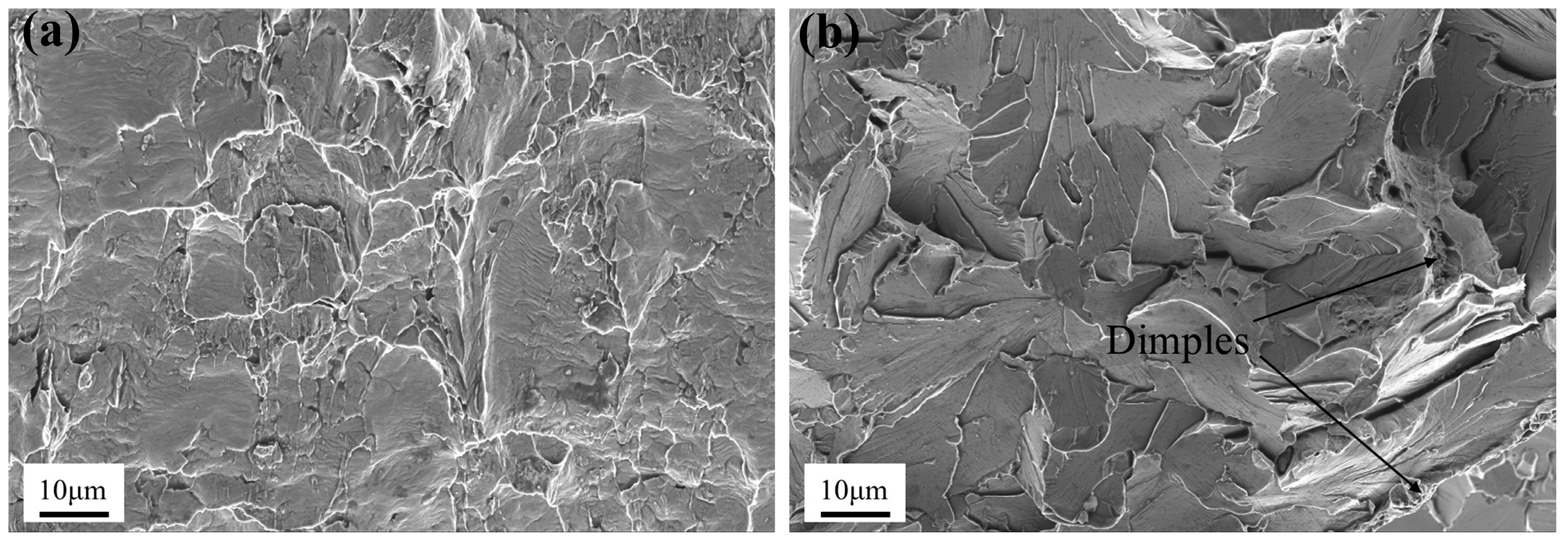
Figure 6 shows the fracture morphology of the impact specimen at 2 mm outside the fusion zone under the heat input of 300 kJ/cm. It can be seen that the fracture near the notch presents quasi-cleavage fracture, while the middle part of the fracture is a typical transgranular cleavage fracture. There are only a very small number of dimples on the fracture surface. This indicates that the impact toughness of the specimen is poor, which is consistent with the results of the impact test.
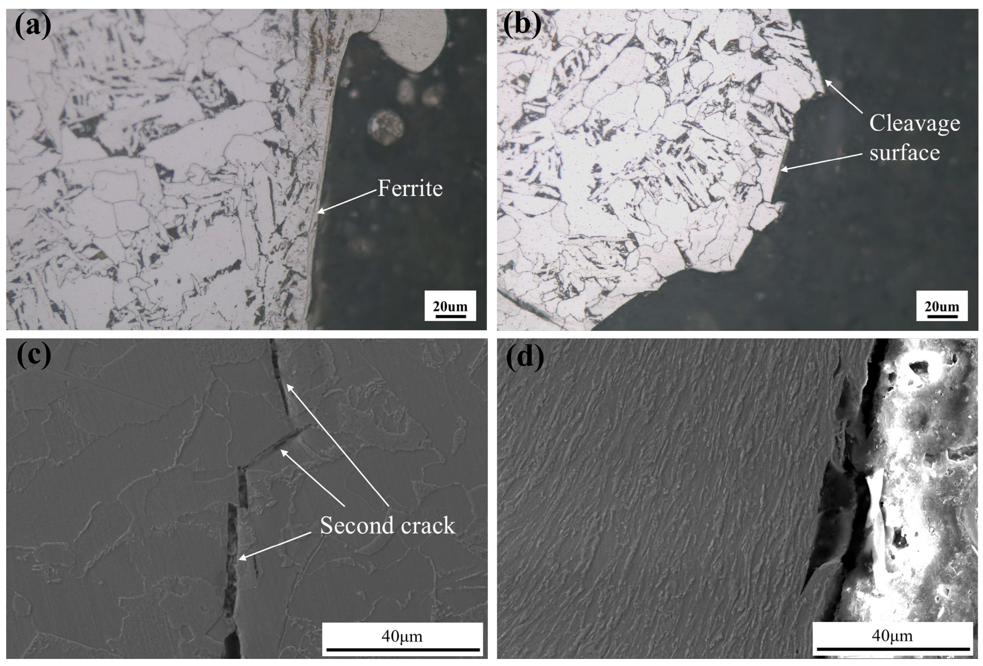
Figure 7 shows the cross-sectional morphology of the impact fracture specimen at 2 mm outside the fusion zone, which is perpendicular to the V-notch. It can be seen that when the heat input is 300 kJ/cm, long strip-shaped grains exist on the fracture surface near the notch. Analysis suggests that these should be coarse, long strip-shaped ferrite in the heat-affected zone. Ferrite has low strength, and under the action of impact load, cleavage crack cores were generated. Multiple cleavage crack cores propagated and finally tore in a plastic manner. From Figure 7a, it can be seen that there are protruding tearing ridges between the quasi-cleavage surfaces. As the distance from the notch increases, the fracture mode of the impact specimen changes from quasi-cleavage fracture to cleavage fracture. Figure 7b shows the morphology of the cross-section of the cleavage zone. It can be seen that the cross-section is composed of flat fracture surfaces crossing ferrite, which correspond to the cleavage surfaces in Figure 6b.
Figure 7c shows the morphology of secondary cracks in the cross-section under high heat input. It can be observed that the fracture surface of the secondary crack is straight, and it runs through ferrite and pearlite. It should be noted that only one secondary crack was observed in the cross-section, indicating that under heat input of 300 kJ/cm, the coarse structure of the heat-affected zone in Q420C steel has a small inhibitory effect on crack propagation, resulting in its lower impact toughness. Besides, the negative interactions between the two neighboring (heterogeneous) phases (bainite and ferrite) may reduce the deformation resistance and promote crack propagation directly [15,16].
Figure 7d is the cross-sectional morphology of the impact specimen under heat input of 25 kJ/cm. The structure near the fracture is mainly fine ferrite and pearlite. These fine structures undergone certain coordinated plastic deformation under the impact load and finally undergo plastic fracture.
It can be seen from the above results that when the sizes of intergranular and intragranular ferrite increase to a certain extent, they will significantly affect the impact toughness of the heat-affected zone.
When the heat input is 25 kJ/cm, the microstructure of the HAZ is fine and dominated by granular bainite. Therefore, both the fusion zone and HAZ exhibit high impact toughness. When the heat input increases to 200 kJ/cm, the microstructure of the overheated zone is still dominated by granular bainite, but blocky ferrite begins to appear near the fusion zone, leading to a decrease in impact toughness at the fusion zone. When the heat input increases to 300 kJ/cm, coarse intergranular ferrite and intragranular ferrite appear both at the fusion zone and in the area relatively far from the fusion zone, resulting in a significant reduction in impact toughness at the fusion zone and 2 mm outside the fusion zone. Therefore, the welding heat input of Q420C steel should be less than 200 kJ/cm.

4. Conclusions

This study investigated the microstructure and mechanical properties of Q420C steel welded joints under different welding heat inputs, and the following conclusions were drawn:
When the heat input increased from 25 kJ/cm to 300 kJ/cm, the primary austenite grains in HAZ were coarsened, and the microstructure of the overheated zone gradually transformed from granular bainite to ferrite + pearlite. When the heat input increased to a certain extent, long strip-shaped ferrite began to form along the primary austenite grain boundaries, while the interior of the primary austenite grains was dominated by blocky ferrite;
When high-strength matching was adopted, the tensile fractures of the welded joints all occurred in the base metal as the welding heat input was within the range of 25 kJ/cm to 300 kJ/cm;
When intragranular ferrite and intergranular ferrite began to appear in HAZ, the impact toughness started to decrease. The higher the heat input, the larger the area with coarse ferrite in the HAZ, and the wider the region where the impact toughness decreased.

Author Contributions

Conceptualization, G.W. and P.W.; methodology, G.W. and J.M.; validation, H.L.; formal analysis, H.L. and X.L.; investigation, H.L.; resources, G.W. and P.W.; data curation, H.L.; writing—original draft preparation, H.L.; writing—review and editing, H.L.; visualization, H.H.; supervision, G.W.; project administration, G.W.; funding acquisition, G.W. and P.W. All authors have read and agreed to the published version of the manuscript.

Funding

This research received no external funding.

Institutional Review Board Statement

Not applicable.

Informed Consent Statement

Not applicable.

Data Availability Statement

Data are contained within the article.

Conflicts of Interest

Authors Hanxin Long, Jinjun Ma and Xiong Luo were employed by the company Guangzhou Shipyard International Co., Ltd. The remaining authors declare that the research was conducted in the absence of any commercial or financial relationships that could be construed as a potential conflict of interest.

References

  1. Men, P.F.; Ho, H.C.; Zhou, X.H.; Chung, K.F. Experimental investigations into stocky composite columns of concrete-filled circular S690 steel tubes under compression. Eng. Struct. 2024, 309, 118016. [Google Scholar] [CrossRef]
  2. Wang, J.; Di, J.; Zhang, Q.; Qin, F.J.; Men, P.F. Local buckling analysis of axially compressed welded box-section stub columns using Q420–Q960 steel. J. Constr. Steel Res. 2023, 210, 108100. [Google Scholar] [CrossRef]
  3. Gong, W.W.; Yang, B.K.; Chen, H.; Chen, Y.; Shen, X.L.; Hao, W.K.; Wang, X.F.; Huang, L.Y. Effects of Ce-La rare earth microalloying on the microstructure and corrosion characteristics of Q420 high-strength steel. Int. J. Electrochem. Sci. 2023, 18, 100242. [Google Scholar] [CrossRef]
  4. Wang, J.; Di, J.; Zhang, Q.; Qin, F.J. Overall buckling behaviour of Q420–Q960 steel welded H-section axial compression members. Eng. Struct. 2021, 249, 113340. [Google Scholar] [CrossRef]
  5. Li, Z.R.; Zhang, D.C.; Wu, H.Y.; Huang, F.H.; Hong, W.; Zang, X.S. Fatigue properties of welded Q420 high strength steel at room and low temperatures. Constr. Build. Mater. 2018, 189, 955–966. [Google Scholar] [CrossRef]
  6. Yang, L.G.; Xing, Y.M. Experimental Study on High-Cycle Fatigue Properties of Q420C Steel at Room Temperature. Mater. Res.-Ibero-Am. J. Mater. 2022, 25, e20210589. [Google Scholar] [CrossRef]
  7. Liu, Y.; Ma, H.; Wang, Z.Y.; Chen, X.H.; Huo, X.X.; Wu, H.Y.; Du, L.X. Effect of Heat Input on Microstructural Evolution and Impact Toughness of the Simulated CGHAZ for a Novel Q690 MPa V-N Medium and Heavy Plate. Mater. 2025, 18, 1148. [Google Scholar] [CrossRef] [PubMed]
  8. Wang, L.B.; Hu, C.Y.; Li, S.B.; Wan, X.L.; Zhong, M.; Hu, F.; Zhou, S.B.; Li, G.Q.; Wu, K.M. Grain Refinement Mechanism in the CGHAZ of Ultra-High-Strength Structural Steel: A Critical Analysis of the Impacts of Prior Austenite Grain and Cooling Rates. JOM 2024, 76, 7120–7134. [Google Scholar] [CrossRef]
  9. Sheng, J.; Ma, J.J.; Wei, F.F.; Meng, Y.H.; Ma, Z.W.; Liang, Y.J.; Duan, H.G. Study on the Mechanical Properties and Constitutive Model of Q420 Steel Under Different Strain Rates. Nano 2025, 20, 2550023. [Google Scholar] [CrossRef]
  10. Xu, Z.B.; Lv, X.W.; Wang, X.Y.; Feng, J.A.; Liu, X.L.; Peng, J.F.; Wu, H. Electrochemically assisted laser surface microtexture preparation and tribological properties research. J. Manuf. Processes 2024, 122, 54–64. [Google Scholar] [CrossRef]
  11. Du, H.; Wen, J.Y.; Song, G.H.; Wu, H.; Feng, J.A.; Wang, Y.J.; Huang, Y.; Yin, Y.S. Effect of inserting a-C layers on anticorrosion behavior of Ni-NiCr-NiCrAlSi composite coating on copper through magnetron sputtering for marine applications. Thin Solid Films 2024, 808, 140558. [Google Scholar] [CrossRef]
  12. An, L.Q.; Jiang, W.Q.; Liu, Y.P.; Shi, Q.; Liu, S.X. Experimental study of mechanical behaviour of angles in transmission towers under freezing temperature. Adv. Steel Constr. 2017, 14, 461–478. [Google Scholar] [CrossRef]
  13. Su, Z. The Application of Q420C Steel in Welding Quality Control of Box-Shaped Beam-Columns for Architectural Steel Structures. Weld. Technol. 2024, 53, 119–122. [Google Scholar]
  14. GB/T 1591—2018; High-Strength Low Alloy Structural Steels. Standards Press of China: Beijing, China, 2018. Available online: https://openstd.samr.gov.cn/bzgk/gb/std_list?r1=public&r2=GB/T%201591 (accessed on 1 August 2025).
  15. Park, S.J.; Heogh, W.; Yang, J.H.; Kang, S.; Jeong, W.; Lee, H.; Jang, T.S.; Jung, H.D.; Jahazi, M.; Han, S.C.; et al. Meta-structure of amorphous-inspired 65.1Co28.2Cr5.3Mo lattices augmented by artificial intelligence. Adv. Compos. Hybrid Mater. 2024, 7, 224. [Google Scholar] [CrossRef] [PubMed]
  16. Kim, S.H.; Lee, H.; Yeon, S.M.; Aranas, C., Jr.; Choi, K.; Yoon, J.; Yang, S.W.; Lee, H. Selective compositional range exclusion via directed energy deposition to produce a defect-free Inconel 718/SS 316L functionally graded material. Addit. Manuf. 2021, 47, 102288. [Google Scholar] [CrossRef]
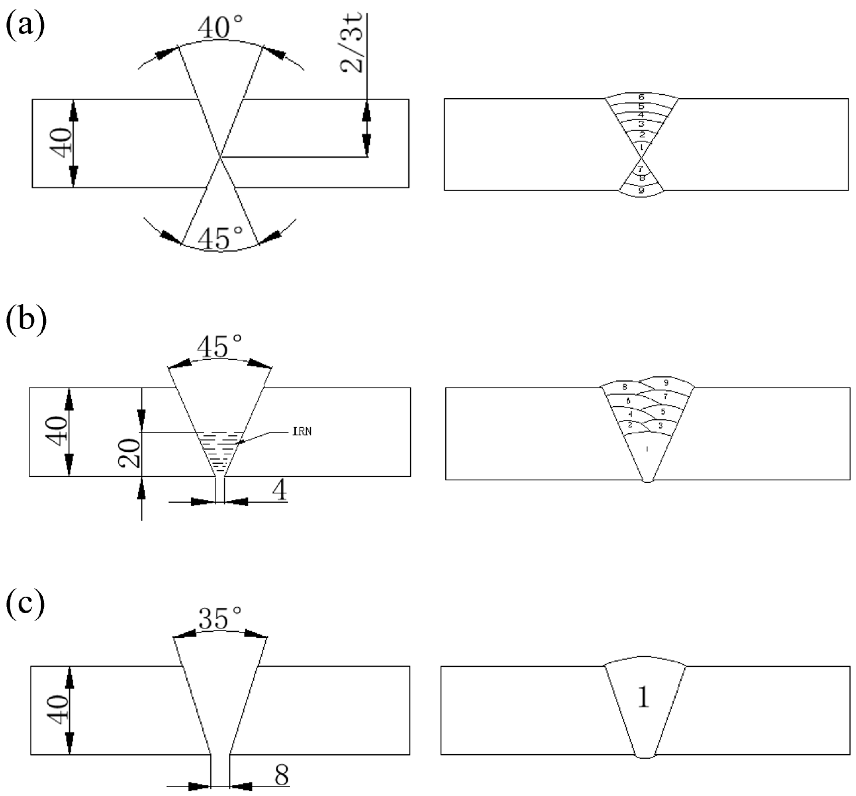
Figure 1. Groove forms and bead distributions: (a) FCAW (LHI); (b) FAB+SAW (MHI, MHHI); (c) EGW (HHI).
Coatings 15 00957 g001
Figure 2. Macroscopic morphologies of welding joints: (a) FCAW (LHI); (b) FAB + SAW (MHI); (c) EGW (MHHI); (d) EGW (HHI).
Coatings 15 00957 g002
Figure 3. Microstructures of Welds and Heat-Affected Zones: (a) FCAW (LHI); (b) FAB + SAW (MHI); (c) EGW (HHI).
Coatings 15 00957 g003
Figure 4. Microstructure of normalized zone (HHI).
Coatings 15 00957 g004
Figure 5. The impact test results of welded joints tested at different temperatures: (a) 0 °C; (b) −20 °C; (c) −40 °C.
Coatings 15 00957 g005
Figure 6. Fracture morphology of FL2 (HHI): (a) Near the notch; (b) Middle part of the fracture.
Coatings 15 00957 g006
Figure 7. Cross-section of impact specimen (FL2): (a) Near the notch (HHI); (b) Middle part of the fracture (HHI); (c) Second crack (HHI); (d) The middle part of the fracture (LHI).
Coatings 15 00957 g007
Table 1. Mechanical properties of Q420C steel.
Tensile Strength (MPa)Yield Strength (MPa)Elongation (%)Charpy Impact Energy (J)
≤100 mm>16 mm∼40 mm>16 mm∼40 mm>16 mm∼40 mm
520∼680≥400≥190 °C≥34
Table 2. Chemical composition of Q420C steel (wt %).
CMnSiAlTiMgNbMoFe
0.061.47 0.25 0.032 0.018 0.002 0.035 0.056 Bal.
Disclaimer/Publisher’s Note: The statements, opinions and data contained in all publications are solely those of the individual author(s) and contributor(s) and not of MDPI and/or the editor(s). MDPI and/or the editor(s) disclaim responsibility for any injury to people or property resulting from any ideas, methods, instructions or products referred to in the content.