Abstract
To achieve superior interfacial bonding between carbon fibers and an Al matrix, this study employed a simplified electroplating system to deposit Ni coatings on carbon fibers using an additive-free electrolyte. The investigation first optimized the carbon fiber heat treatment process, followed by systematic examination of electroplating parameters affecting the Ni coating microstructure. Key findings demonstrate that (1) thermal treatment of carbon fibers significantly enhances their wettability with the electroplating solution; (2) controlled deposition of smooth, uniform, and continuous Ni coatings requires precise optimization of nickel sulfate concentration, applied voltage, and pH value. This work establishes a cost-effective technical foundation for producing high-quality Ni-coated carbon fibers.
1. Introduction
Carbon fibers are widely used in the reinforcement of composites such as metals, resins, and ceramics due to their excellent properties, such as light weight, high strength, high modulus, chemical stability, and low coefficient of thermal expansion [1,2,3,4,5]. Carbon fiber-reinforced aluminum (Al) matrix composites are a class of metal matrix composites that synergistically combine the advantages of carbon fibers and Al. These composites exhibit low density, high specific strength and stiffness, negligible moisture absorption, and excellent corrosion resistance, making them ideal for structural components in ships, aircraft, and other high-performance equipment [6,7]. However, when preparing carbon fiber-reinforced Al matrix composites, the poor wettability between carbon fibers and the Al matrix poses a challenge. This hinders the penetration of molten Al into the carbon fiber bundles, ultimately compromising the mechanical properties of the composites [8]. On the other hand, the interfacial reaction between carbon fibers and the Al matrix under high-temperature processing conditions tends to form needle-like brittle Al4C3, which degrades the interfacial bonding strength of the composites [9].
To enhance the wettability between carbon fibers and the Al matrix while inhibiting severe interfacial reactions, surface coating of carbon fibers is an effective approach [10,11]. Zhang et al. [12] fabricated carbon fiber-reinforced Al matrix composites using an electromagnetic casting method. To enhance the wettability between the carbon fibers and Al matrix, a Ni/P coating was chemically deposited on the carbon fiber surface. The effects of different stabilizers on the coating microstructure were investigated, with results demonstrating that the coating prepared using lactic acid as the stabilizer exhibited optimal performance. Hua et al. [13] employed an electroplating process to deposit a Ni coating on the carbon fiber surface to enhance the interfacial bonding between the fibers and Al matrix. By introducing NiCl2, sodium dodecyl sulfate (C12H25NaSO4), and other additives into the electroplating solution, they achieved a uniformly smooth coating on the carbon fibers. Ko et al. [14] evaluated the wettability of Cu coating on the graphite surface with Al liquid. The Cu coating was deposited through both electroless plating and ion sputtering techniques. Results showed that the coating could reduce the contact angle between graphite and molten aluminum by up to 55°, attributed to the interdiffusion of Cu and Al atoms at the interface. Che et al. [15] introduced a new process for chemical Cu coating on the surface of carbon fiber without precious metal catalysts. They employed a Ni sulfate solution as the catalyst for chemical Cu coating on the carbon fiber surface. Subsequent phase analysis revealed that the deposited coating contained Ni impurities. While both Ni and Cu coatings enhance the wettability between molten Al and carbon fibers, Ni coatings demonstrate superior performance. The higher diffusion rate of Cu in molten Al compared to Ni increases the risk of interfacial reaction and carbon fiber degradation [16]. A comprehensive review of carbon fiber surface modification techniques reveals that electrodeposition and electroless plating currently dominate the coating methodologies. Nevertheless, electrodeposition proves more efficient than electroless plating for carbon fiber coating. This process offers straightforward operation and short deposition cycles, making it particularly suitable for commercial-scale production [17,18,19]. Despite the numerous benefits of electrodeposition technology, specific technical difficulties arise when depositing coatings on carbon fibers [20]. Due to their small diameter, carbon fibers exhibit high surface energy and a large specific surface area. This characteristic leads to fiber agglomeration in plating solutions, making it particularly challenging to achieve uniform coating deposition on individual fibers within fiber bundles during the electrodeposition process [21,22]. It is frequently required to add additives to the electroplating solution to increase the carbon fibers’ wettability with the electroplating solution in order to coat their surface uniformly [13]. However, the cost of electroplating will go up if one adds additives to the electroplating solution. Additionally, the additives will be deposited on the carbon fibers’ surface, which will weaken the interfacial bonding in the carbon fiber-reinforced Al matrix composites [23,24].
In this work, the process of electroplating Ni coatings on the surface of carbon fibers was examined under the condition of an electroplating solution without additives in order to coat the surface of carbon fibers uniformly and create coatings free of impurity components. Although Ni coatings can be applied to carbon fiber surfaces using additive-free electroplating solutions, the resulting coatings show uneven deposition, especially on the inner fibers of carbon fiber bundles, where it is still difficult to achieve uniform Ni coating coverage. The poor wettability of carbon fibers and the electroplating solution is the main cause of this problem. To enhance the wettability between carbon fibers and the electroplating solution, the effect of surface heat treatment on the dispersion performance of carbon fibers in aqueous solutions was investigated. Furthermore, the influence of electroplating parameters on coating thickness and microstructure was systematically investigated and optimized, ultimately achieving a smooth, uniform Ni coating with strong adhesion to the carbon fiber surface.
2. Materials and Methods
2.1. Starting Materials
The substrate utilized in this study comprised T300 carbon fibers, manufactured by Toray Industries, Japan. The carbon fibers possess a diameter of 6–8 μm and a density of 1.76 g/cm3, and are composed of 3000 monofilaments per bundle. The basic Ni electroplating solution contained only nickel sulfate (NiSO4) and boric acid (H3BO3), with no additives included in the formulation. Carbon fibers are typically manufactured through a series of processes including precursor preparation, pre-oxidation treatment, carbonization, graphitization, and sizing application. In this process, epoxy- or polyurethane-based sizing agents are generally applied to protect the fibers and facilitate handling during transportation. Before electroplating, the surface of the carbon fiber was heated under atmospheric conditions to enhance its dispersion in the electroplating solution. The carbon fibers to be electroplated were placed in a heat treatment furnace and thermally treated for 30 min at 300 °C, 500 °C, and 700 °C in an ambient atmosphere. The carbon fibers were then extracted for the subsequent deposition of a Ni coating.
2.2. Electrodeposition of Ni Coatings on Carbon Fiber Surfaces
The process of electroplating Ni coatings on the carbon fiber surfaces is shown in Figure 1. First, a specific quantity of nickel sulfate and boric acid reagent is dissolved in deionized water, and the reagent is thoroughly stirred to dissolve it completely, to create the electroplating solution. Subsequently, the prepared electroplating solution is transferred into the electroplating tank. The carbon fiber cathode is positioned at one extremity of the tank and connected to the negative terminal of the power supply, while the Ni anode is placed at the opposing extremity and connected to the positive terminal. A constant voltage was applied between the carbon fiber cathode and the Ni anode throughout the electrodeposition process. Upon completion of the plating, the coated carbon fibers were extracted, rinsed thoroughly, and subsequently placed in a vacuum desiccator for drying prior to further performance characterization.
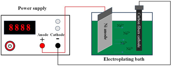
Figure 1.
Schematic of the electroplating setup for Ni deposition on carbon fibers.
2.3. Characterization Method
The phase composition of the coating was characterized by X-ray diffraction (XRD) with a scanning range of 2θ = 20–80° at a step size of 0.02° and a scanning rate of 5°/min. The surface morphology and cross-sectional thickness of the coating were examined using scanning electron microscopy (SEM). Additionally, energy-dispersive spectroscopy (EDS) was employed to analyze the elemental composition of specific regions. Microstructural characterization was systematically performed across distinct regions of the coating, with representative zones subsequently identified and subjected to comprehensive analysis. The tensile properties of carbon fiber monofilaments were evaluated using a universal mechanical testing machine, comparing their mechanical behavior before and after heat treatment. The bonding strength between the carbon fiber and the coating was evaluated using thermal shock testing.
3. Results
3.1. Surface Degumming Treatment of Carbon Fiber
To mitigate mechanical damage during packaging and transportation, carbon fibers are typically coated with a protective adhesive layer during manufacturing. Thus, a thermal treatment process must be applied to carbon fibers before electroplating to remove the protective adhesive layer, ensuring homogeneous distribution and optimal solution contact during subsequent electrodeposition [25]. Figure 2 shows the microscopic morphology of the carbon fiber surface obtained under different heat treatment conditions. It is evident that varying heat treatment temperatures result in distinct surface alterations for carbon fiber. Figure 2a,b display the surface microstructure of pristine carbon fibers prior to thermal treatment. Figure 2a,b reveal that the untreated carbon fibers exhibit a tightly bonded morphology, with particulate matter observed on the fiber surfaces. These surface particles likely originate from localized aggregation of the sizing agent. The sizing agent on carbon fiber surfaces not only hinders sufficient contact between the fibers and electroplating solution, but also adversely affects the electrical conductivity during the electroplating process [26]. Figure 2c shows the microstructure of the carbon fiber surface after a 30 min heat treatment at 300 °C in an atmosphere environment. Microscopic analysis reveals that the fiber surface exhibits significant cleaning, with distinct longitudinal striations along the fiber axis, suggesting removal of surface sizing agents. Figure 2d shows the microstructure of the carbon fiber surface after a 30 min heat treatment at 500 °C in an atmosphere environment. Similarly, the carbon fiber surface exhibits an exceptionally clean morphology, devoid of any detectable impurities. However, compared to Figure 2c, the surface striations of the carbon fiber are deeper. Figure 2e shows the microstructure of the carbon fiber surface after a 30 min heat treatment at 700 °C in an atmosphere environment.
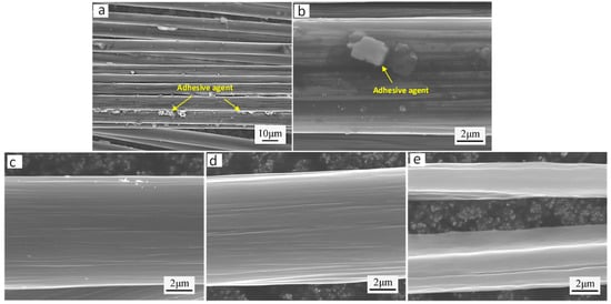
Figure 2.
Surface microstructural evolution of carbon fibers under varying heat treatment conditions: (a,b) as-received carbon fiber surface; (c) carbon fiber surface treated at 300 °C for 30 min; (d) carbon fiber surface treated at 500 °C for 30 min; (e) carbon fiber surface treated at 700 °C for 30 min.
To elucidate the influence of heat treatment temperature on the dimensional characteristics and tensile strength of carbon fibers, comprehensive measurements of fiber diameter and tensile mechanical properties were conducted following controlled thermal processing under varying temperature conditions. The results demonstrate that the carbon fibers maintained an average diameter of approximately 7 μm both in the untreated condition and following heat treatment at 300–500 °C. However, a significant diameter reduction to 5 μm was observed when the heat treatment temperature reached 700 °C. Single-fiber tensile testing revealed that the as-received carbon fibers exhibited a tensile strength of 2.7 GPa. Following thermal treatment at 300 °C and 500 °C, the fibers demonstrated comparable strength retention, maintaining values of approximately 2.6 GPa. In contrast, specimens subjected to 700 °C treatment showed a statistically significant reduction in tensile strength to 2.3 GPa, indicating the onset of thermal degradation at elevated temperatures. Thus, it is evident that heat treatment at 700 °C for 30 min weakens carbon fiber by causing some structural damage.
To observe the dispersibility of carbon fibers derived from various heat treatments in an aqueous solution, Figure 3 illustrates this process. Figure 3 demonstrates that both as-received and 300 °C-treated carbon fibers exhibit negligible dispersibility in the aqueous solution. The poor dispersion behavior of untreated fibers can be attributed to the presence of a sizing agent coating on their surfaces, which significantly compromises their hydrophilic properties. However, the low treatment temperature at 300 °C may result in fewer oxygen functional groups on the fiber surface, which is why carbon fibers treated at this temperature cannot disperse in an aqueous solution [27]. The filaments of carbon fibers treated at 500 °C and 700 °C disperse in the aqueous solution and come into full contact with it, demonstrating superior dispersibility in aqueous solutions as compared to untreated carbon fibers and those treated at 300 °C. However, 700 °C thermal treatment induces severe structural degradation and mechanical deterioration in carbon fibers. To achieve homogeneous dispersion in the electroplating bath while ensuring complete metallic coating on individual filaments, optimal results were obtained through atmospheric thermal treatment at 500 °C for 30 min, which preserves fiber integrity while providing adequate surface activation.
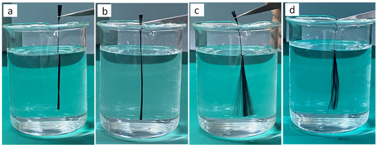
Figure 3.
Dispersibility of carbon fibers in aqueous solutions under different heat treatment conditions: (a) as-received carbon fiber; (b) carbon fiber heat-treated at 300 °C; (c) carbon fiber heat-treated at 500 °C; (d) carbon fiber heat-treated at 700 °C.
3.2. Effect of Nickel Sulfate Concentration on the Microstructure of Ni Coating
To systematically investigate the influence of nickel sulfate (NiSO4) concentration (ranging from 42 to 162 g/L) on the microstructural evolution of electrodeposited Ni coatings, a series of controlled electroplating experiments was conducted while maintaining the following constant parameters: pH 4.1, applied potential 6 V, bath temperature 25 °C, and deposition duration 60 s. Figure 4 shows the microstructure of Ni coatings obtained under different nickel sulfate concentrations. When the concentration of nickel sulfate is 42 g/L, as shown in Figure 4a,e,i, a uniformly smooth Ni coating is formed on the carbon fiber surface, although it is rather thin in thickness. This is because low concentrations of nickel sulfate result in low quantities of Ni2+, which causes a slower rate of Ni deposition on carbon fibers and a thinner nickel coating. When the nickel sulfate concentration is increased to 82 g/L, the Ni coating deposited on the carbon fiber surface not only is smooth and uniform, but also has a clear outline and is tightly bonded to the carbon fiber, as shown in Figure 4b,f,j. On the one hand, heat treatment enables complete contact between the carbon fiber filaments and the electroplating solution. However, an adequate amount of Ni2+ can also speed up the Ni coating’s deposition. When the nickel sulfate concentration increased to 122 g/L and 162 g/L, as shown in Figure 4c,d,g,h,k,l, not only was the Ni coating on the carbon fiber surface smooth and uniform, but its thickness also increased. According to the analysis, the thickness of the Ni coating is influenced by the content of nickel sulfate in the electroplating solution. This could be because varying concentrations of nickel sulfate differ in the rate at which Ni atoms are deposited. Therefore, the concentration of nickel sulfate must be higher than 42 g/L to achieve a uniform, smooth Ni coating of a specific thickness on the carbon fiber surface.
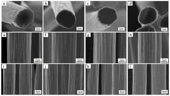
Figure 4.
Microscopic morphology of Ni coatings obtained under different nickel sulfate concentrations: (a,e,i) NiSO4 concentration 42 g/L; (b,f,j) NiSO4 concentration 82 g/L; (c,g,k) NiSO4 concentration 122 g/L; (d,h,l) NiSO4 concentration 162 g/L.
The phase composition of the obtained Ni coating was analyzed, as shown in Figure 5. Figure 5a shows the XRD analysis of the carbon fiber surface before and after the deposition of the Ni coating. From the diffraction pattern, it can be seen that broadened carbon peaks were detected in the uncoated carbon fiber. XRD analysis of the electrodeposited Ni-coated carbon fibers revealed distinct diffraction peaks corresponding to both carbon and metallic Ni, with no detectable impurity phases. This high phase purity directly results from the additive-free electroplating bath composition, which prevented the co-deposition of contaminants. The Ni coating’s cross-section was subjected to EDS line scanning analysis in order to better examine the Ni distribution surrounding the carbon fibers, as seen in Figure 5b,c. As evidenced in the figure, only Ni and carbon elements were detected. Furthermore, the continuous gradient transition in elemental composition profiles demonstrates strong interfacial bonding between the carbon fiber and Ni coating, with no evidence of delamination or abrupt compositional discontinuities.
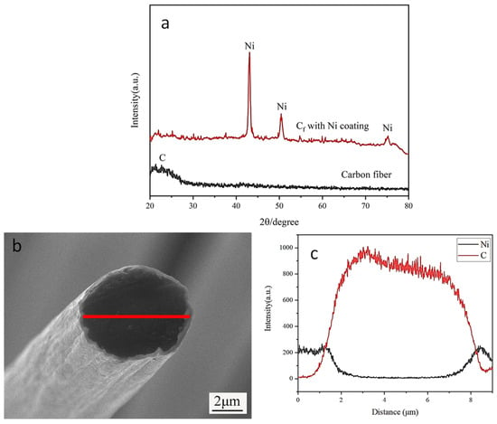
Figure 5.
Component analysis of Ni coating on carbon fiber surface: (a) Ni coating XRD analysis; (b,c) EDS line scan analysis of Ni coating cross-section.
3.3. Effect of Deposition Voltage on the Microstructure of Ni Coating
To systematically investigate the influence of deposition voltage (varied from 3 to 9 V) on the microstructure of Ni coatings, a series of electrodeposition experiments was conducted under controlled conditions: pH 4.1, nickel sulfate concentration 122 g/L, bath temperature 25 °C, and deposition duration 60 s. Coating thickness was quantitatively characterized for each voltage condition. Figure 6 shows the microstructure of Ni coatings obtained under different deposition voltage conditions. As seen in Figure 6a,e,i, a thin layer of Ni is formed on the carbon fiber surface when the deposition voltage is 3 V. The Ni coating’s shape is not entirely evident. The coating thickness, as determined by measurement and computation, was roughly 52 nm. The reason for this is that at low voltages, Ni2+ acquires electrons slowly, which results in a poor nucleation rate. This makes it harder for Ni to deposit on the carbon fiber surface, which leads to a thinner coating. As seen in Figure 6b,f,j, a uniform and complete Ni coating forms around the carbon fiber when the voltage is raised to 5 V. The coating is firmly bound to the fiber and has a thickness of around 470 nm. When the voltage was further increased to 7 V, the Ni coating continued to uniformly and completely cover the fibers, with a coating thickness of approximately 645 nm, as shown in Figure 6c,g,k. As demonstrated in Figure 6d,h,l, deposition at 9 V resulted in the formation of localized porosity within the Ni coating. This morphological defect can be attributed to the hydrogen evolution reaction under high-potential conditions, where gas bubble incorporation during electrodeposition generates void structures. Measurement of the coating thickness shows a value of approximately 693 nm. Therefore, it was found that the deposition voltage affects the thickness of the Ni coating. Furthermore, both excessively high and low applied voltages fail to produce optimal coatings on carbon fibers. Systematic characterization reveals that maintaining the deposition voltage within the range of 5–7 V yields coatings with better structure.
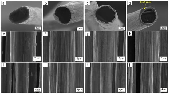
Figure 6.
Microscopic morphology of Ni coating obtained under different deposition voltage conditions: (a,e,i) voltage 3 V; (b,f,j) voltage 5 V; (c,g,k) voltage 7 V; (d,h,l) voltage 9 V.
3.4. Effect of Electroplating Solution pH Value on the Microstructure of Ni Coating
To investigate the effect of pH on the microstructure of Ni coatings, Ni coatings were prepared under different pH conditions (pH = 3.7–4.8). Other electroplating process parameters were as follows: voltage 6 V; temperature 25 °C; nickel sulfate concentration 122 g/L; and plating time 60 s. Figure 7 shows the microstructure of Ni coatings obtained under different pH conditions. The carbon fiber surface is completely and uniformly coated with Ni coating when the pH reaches 3.7, as shown in Figure 7a,e,i. When the pH value rises to 4.1, the coating is also found to be smooth and uniform, as shown in Figure 7b,f,j. When the pH value was 4.3, although the carbon fiber surface was completely coated with the Ni coating, the coating appeared rough with coarse Ni particles, as shown in Figure 7c,g,k. However, when the pH value further increased to 4.8, it can be observed from Figure 7d,h,l that the Ni coating failed to fully cover the carbon fiber surface, leaving some exposed regions. This is because an excessively high pH (4.8) accelerates the consumption of H+ near the cathode during electroplating, further increasing the local OH− concentration. The reaction between OH− and Ni2+ generates Ni(OH)2 colloids, reducing the available Ni2+ near the electrode and consequently slowing the Ni deposition rate on the carbon fiber surface [28]. Therefore, in order to deposit a complete Ni coating on the carbon fiber surface, the pH value of the electroplating solution must be maintained between 3.7 and 4.3.
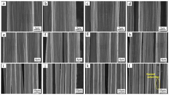
Figure 7.
Microscopic morphology of Ni coatings obtained under different pH conditions of electroplating solutions: (a,e,i) pH value 3.7; (b,f,j) pH value 4.1; (c,g,k) pH value 4.3; (d,h,l) pH value 4.8.
3.5. Bond Strength Test Between Ni Coating and Carbon Fiber
The interfacial adhesion between the carbon fiber and coating was evaluated using thermal shock testing. The procedure consisted of (1) immersing the coated carbon fiber in boiling water for 20 min, (2) rapidly transferring it to ice water (0–5 °C) for 5 min, and (3) repeating this cycle six times. Post-test, the coating’s surface morphology was examined, and the bonding strength was assessed based on the degree of coating delamination. Figure 8 shows the microstructure of the Ni coating on the surface of carbon fiber before and after thermal shock. It was observed that after thermal shock testing, only minor delamination occurred in the Ni coating on the carbon fiber surface, while the majority of the coating remained intact and uniformly adhered to the substrate. Mass measurements of the Ni coating on carbon fiber surfaces before and after thermal shock testing revealed a minimal mass loss rate of merely 1.1%, demonstrating excellent interfacial adhesion between the Ni coating and carbon fiber.
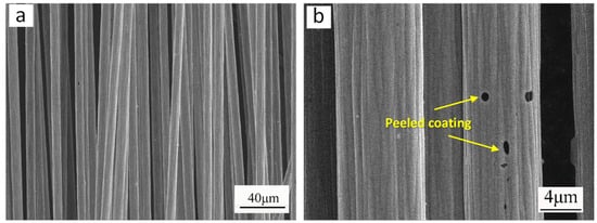
Figure 8.
Microscopic morphology of Ni coating on carbon fiber surface before and after thermal shock: (a) microstructure of Ni coating before thermal shock; (b) microstructure of Ni coating after thermal shock.
4. Discussion
4.1. Analysis of the Effect of Heat Treatment on the Dispersibility of Carbon Fibers
Untreated carbon fibers demonstrate poor dispersibility in aqueous solutions due to two key factors: (1) the presence of a surface sizing agent that promotes inter-fiber adhesion through its binding effects, and (2) their inherently low specific surface area coupled with surface hydrophobicity. The sizing layer not only creates strong adhesive forces between fibers but also reduces surface energy, while the limited surface area and hydrophobic nature further inhibit effective wetting and dispersion in water-based systems. High-temperature thermal treatment not only completely removes the sizing agent from the carbon fiber surface, thereby increasing its specific surface area, but also induces surface oxidation, enhancing the content of oxygen-containing functional groups (e.g., hydroxyl [–OH], carbonyl [C=O], and carboxyl [–COOH]). These modifications significantly improve the wettability of carbon fibers in aqueous solutions. During oxidative treatment, the abundant C-H bonds on the carbon fiber surface are readily converted into polar oxygen-containing functional groups. These groups facilitate hydrogen bonding with water molecules, thereby enhancing surface hydrophilicity and promoting interfacial wetting [29].
4.2. Analysis of the Effect of Nickel Sulfate Concentration on the Deposition Rate of Electroplated Ni Coatings
To further investigate the influence of nickel sulfate concentration in the electroplating bath on the Ni coating deposition rate, Ni coatings were prepared on carbon fibers of equal mass under varying nickel sulfate concentrations. The deposition rate was subsequently calculated using the following equation:
where
= deposition rate (mg/min); m = mass of uncoated fiber (mg); M = mass of plated fiber (mg); and t = electroplating time (min).
Figure 9 shows the relationship curve between nickel sulfate concentration and the deposition rate of the Ni coating on the carbon fiber surface. When the nickel sulfate concentrations were 42, 82, 122, and 162 g/L, the corresponding Ni coating deposition rates measured 2.32, 3.32, 3.82, and 3.92 mg/min, respectively. It was observed that the deposition rate of Ni coatings on carbon fibers increased with rising nickel sulfate concentration, while the rate of increase gradually diminished. This phenomenon is attributed to the predominant electrochemical reactions occurring during nickel electroplating:
Anode (Oxidation): Ni(s)−2e− → Ni2+(aq)
Cathode (Reduction): Ni2+(aq) + 2e− → Ni(s)
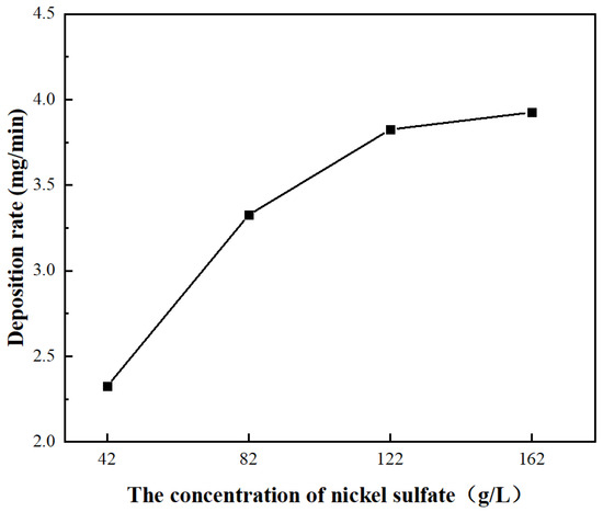
Figure 9.
Relationship curve between the concentration of nickel sulfate in the electroplating solution and the deposition rate of the Ni coating on the surface of carbon fiber.
Thus, at higher nickel sulfate concentrations, the increased Ni2+ availability in the electroplating bath enhances nickel reduction, accelerating the Ni coating deposition rate. However, under a fixed electric field, the limited surface charge density of carbon fibers results in progressively diminishing enhancement of Ni deposition rates as nickel sulfate concentration exceeds a certain level.
4.3. Analysis of the Effect of Deposition Voltage on Ni Coating Thickness
The thickness of the Ni coatings was examined after they were created under various voltage circumstances (3–9 V) in order to examine the impact of the deposition voltage on the coatings. Figure 10 shows the relationship curve between Ni coating thickness and deposition voltage. It can be seen from the figure that the coating thickness varies almost linearly with the deposition voltage. Derived from Faraday’s Law, the coating thickness correlates with applied voltage through the following equation [30]:
where
= coating thickness;
= electrochemical equivalent of coating (constant);
= current density;
= electroplating duration;
= current efficiency;
= coating density;
= conductivity;
= applied voltage; and
= inter-electrode distance.
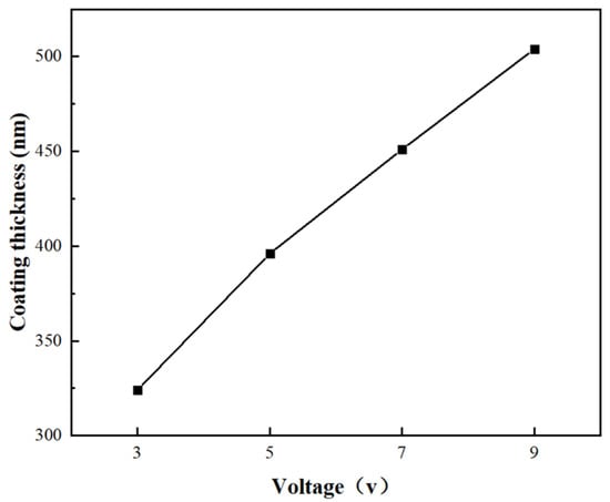
Figure 10.
Relationship curve between Ni coating thickness and deposition voltage.
As derived from the relationship, the coating thickness exhibits a proportional dependence on deposition voltage when the following parameters remain constant: electroplating duration, electrochemical equivalent, coating density, current efficiency, conductivity, and inter-electrode distance. This theoretical prediction aligns precisely with the experimentally measured thickness–voltage correlation curve presented in this study.
4.4. Analysis of the Effect of Electroplating Solution pH Value on Ni Coating Grain Size
To analyze the effect of the pH value of the electroplating solution on the crystallite size of Ni coatings, the Scherrer formula was used to quantitatively determine the crystallite size of Ni coatings obtained under different pH conditions. The calculation formula is as follows [31]:
where β = the value of full width at half maximum (FWHM); θ = the Bragg angle; K = the shape factor, with the value being 0.94; λ = the X-ray diffraction wavelength; and d = the crystallite size.
The crystallite size measured from diffraction peaks does not represent the true crystallite size, but it can serve as a reference for relative comparison. In this work, based on the formula mentioned above, the crystallite size was calculated using the full width at half maximum (FWHM) of the (110) diffraction peak. Figure 11 shows the effect of the pH value of the electroplating solution on the crystallite size of the Ni coating. Figure 11a shows the XRD patterns of Ni coatings obtained under different pH conditions. Figure 11b shows the crystallite size of the Ni coating obtained by calculation. It was found that the Ni crystallite size was smaller at pH 3.7 and 4.1, while larger crystallite sizes were obtained at pH 4.3 and 4.8. This result is consistent with the observed microstructure of the Ni coatings shown in Figure 7. This is because during the electroplating process, in addition to the redox reaction of Ni2+ at the electrode, the following side reactions also occur:
2H2O−4e− → 4H+ + O2↑
2H+ + 2e− → H2↑
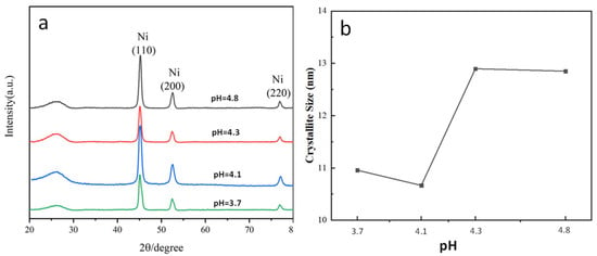
Figure 11.
Effect of pH value of electroplating solution on crystallite size of Ni coating: (a) XRD patterns of Ni coatings obtained under different pH conditions; (b) crystallite size of Ni coatings obtained under different pH conditions.
Consequently, when the pH value is too high, the rapid consumption of H+ near the cathode during the electroplating process leads to a corresponding increase in OH− concentration. The elevated OH− then reacts with Ni2+ to form Ni(OH)2 colloids, which adhere to the carbon fiber surface. This adhesion subsequently suppresses the nucleation and precipitation of Ni crystals, ultimately resulting in coarsened Ni crystallite sizes [32].
4.5. Elemental Analysis of Ni Coating Obtained Under Additive-Free Electroplating Conditions
Figure 12 presents the microstructure and elemental mapping analysis of Ni coatings electrodeposited on carbon fibers from additive-free electroplating solutions. It can be observed that the Ni coating was uniformly deposited on the carbon fiber surface, exhibiting strong interfacial bonding with the substrate. The coating technique suggested in this study not only produces higher-purity Ni coatings but also shows reduced production costs when compared to traditional nickel coatings deposited from additive-containing electroplating solutions. Additionally, this coating can significantly improve the interfacial bonding between carbon fibers and the Al matrix when used on carbon fiber-reinforced Al matrix composites [21,22,28]. The present work successfully deposited high-quality Ni coatings onto carbon fiber without employing any additives. This result can be attributed to two key factors: first, the degumming treatment of carbon fibers enabled their uniform dispersion in the electroplating solution, ensuring sufficient contact with the electrolyte; second, the optimized electroplating parameters significantly improved the deposition quality of Ni coatings. This study provides technical support for the electrodeposition of high-purity Ni coatings on carbon fiber surfaces using a low-cost plating process.
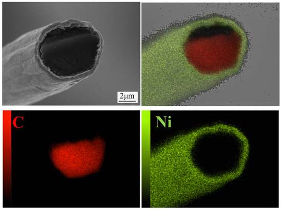
Figure 12.
EDS elemental mapping analysis of Ni coating on carbon fiber surface.
5. Conclusions
To achieve high-quality Ni coatings on carbon fibers through additive-free electroplating, this study examined (1) the effect of carbon fiber heat treatment on fiber dispersibility in the electroplating solution, and (2) the influence of electroplating parameters on coating microstructure. Through systematic parameter optimization, the following conclusions were drawn:
- (1)
- In an ambient atmosphere, a 500 °C heat treatment for 30 min effectively removes sizing agents from carbon fiber surfaces. This process increases fiber surface area and energy while enhancing wettability with the electrodeposition solution, without compromising the structural integrity or mechanical strength of the fibers.
- (2)
- The microstructure of Ni coatings was examined in this work in relation to the concentration of nickel sulfate in the electroplating solution. The results demonstrate that a nickel sulfate concentration exceeding 42 g/L is essential to deposit uniform, smooth Ni coatings with controlled thickness on carbon fiber surfaces.
- (3)
- The effect of deposition voltage on the microstructure of Ni coatings was investigated in this work. The findings show that the ideal coating structure is produced by keeping the voltage between 5 and 7 V.
- (4)
- The effect of electroplating solution pH on the microstructure of Ni coatings was examined in this work. According to the findings, continuous Ni coating deposition on carbon fiber surfaces requires the electrolyte pH to be kept between 3.7 and 4.3.
- (5)
- Thermal shock testing demonstrated excellent interfacial bonding between the Ni coatings and carbon fibers prepared in this study.
- (6)
- This study provides technical support for electroplating high-purity Ni coatings on carbon fiber surfaces, and this technology has already enabled small-scale industrial production of Ni-coated carbon fibers.
Author Contributions
Y.J. and Z.L.: methodology; R.Z.: software; W.H.: validation; Y.J., R.Z. and X.X.: formal analysis; Y.J.: investigation; W.H.: resources; Y.J.: data curation; Y.J.: writing—original draft preparation; Z.L.: writing—review and editing; R.Z.: visualization; Z.L.: supervision; W.H.: project administration; X.X.: funding acquisition. All authors have read and agreed to the published version of the manuscript.
Funding
This research was funded by Xi’an Youth Talent Support Program, grant number 959202313059, and the Innovation and Entrepreneurship Training Program for College Students, grant number S202410702092.
Institutional Review Board Statement
Not applicable.
Informed Consent Statement
Informed consent was obtained from all subjects involved in the study.
Data Availability Statement
The data presented in this study are available on request from the corresponding author. The data are not publicly available due to privacy.
Conflicts of Interest
The authors declare that the research was conducted in the absence of any commercial or financial relationships that could be construed as potential conflicts of interest.
References
- Tomaru, T.; Shimanoe, H.; Hong, S.; Ha, S.-J.; Jeon, Y.-P.; Nakabayashi, K.; Miyawaki, J.; Yoon, S.-H. Preparation of spinnable mesophase pitch from pyrolyzed fuel oil by pressurized heat treatment and its application of carbon fiber. Carbon 2024, 226, 119160. [Google Scholar] [CrossRef]
- Banerjee, C.; Chandaliya, V.K.; Dash, P.S. Recent advancement in coal tar pitch-based carbon fiber precursor development and fiber manufacturing process. J. Anal. Appl. Pyrolysis 2021, 158, 105272. [Google Scholar] [CrossRef]
- Mahaviradhan, N.; Sivaganesan, S.; Sravya, N.P.; Parthiban, A. Experimental investigation on mechanical properties of carbon fiber reinforced aluminum metal matrix composite. Mater. Today Proc. 2021, 39, 743–747. [Google Scholar] [CrossRef]
- Guo, H.; Huang, Y.D.; Liu, L.; Shi, X.H. Effect of epoxy coatings on carbon fibers during manufacture of carbon fiber reinforced resin matrix composites. Mater. Des. 2010, 31, 1186–1190. [Google Scholar] [CrossRef]
- Arai, Y.; Inoue, R.; Goto, K.; Kogo, Y. Carbon fiber reinforced ultra-high temperature ceramic matrix composites: A review. Ceram. Int. 2019, 45, 14481–14489. [Google Scholar] [CrossRef]
- Zhong, K.; Zhou, J.M.; Zhao, C.T.; Yun, K.; Qi, L.H. Effect of interfacial transition layer with CNTs on fracture toughness and failure mode of carbon fiber reinforced aluminum matrix composites. Compos. Part A Appl. Sci. Manuf. 2022, 163, 107201. [Google Scholar] [CrossRef]
- Wei, W.F.; Liao, Q.H.; Yang, Z.F.; Li, X.B.; Huang, Z.; Ren, J.; Yang, Y.; Wu, G. Interfacial modification and performance enhancement of carbon matrix/aluminum composites. J. Alloys Compd. 2022, 903, 163877. [Google Scholar] [CrossRef]
- Matsunaga, T.; Matsuda, K.; Hatayama, T.; Shinozaki, K.; Yoshida, M. Fabrication of continuous carbon fiber-reinforced aluminum–magnesium alloy composite wires using ultrasonic infiltration method. Compos. Part A Appl. Sci. Manuf. 2007, 38, 1902–1911. [Google Scholar] [CrossRef]
- Zhang, Y.H.; Wu, G.H. Comparative study on the interface and mechanical properties of T700/Al and M40/Al composites. Rare Met. 2010, 29, 102–107. [Google Scholar] [CrossRef]
- Ip, S.; Sridhar, R.; Toguri, J.; Stephenson, T.; Warner, A. Wettability of nickel coated graphite by aluminum. Mater. Sci. Eng. A 1998, 244, 31–38. [Google Scholar] [CrossRef]
- Zhong, K.; Zhou, J.; Zhao, C.; Yun, K.; Qi, L. The effect of nickel coating on the mechanical properties and failure modes of continuous carbon fiber reinforced aluminum matrix composites. J. Alloys Compd. 2022, 904, 164134. [Google Scholar] [CrossRef]
- Zhang, J.J.; Liu, S.C.; Lu, Y.P.; Dong, Y.; Li, T.J. Fabrication process and bending properties of carbon fibers reinforced Al-alloy matrix composites. J. Mater. Process. Technol. 2016, 231, 366–373. [Google Scholar] [CrossRef]
- Hua, Z.; Liu, Y.; Yao, G.; Wang, L.; Ma, J.; Liang, L. Preparation and characterization of nickel-coated carbon fibers by electroplating. JMEPEG 2012, 21, 324–330. [Google Scholar] [CrossRef]
- Ko, Y.J.; Yoon, J.; Lee, J.; Han, J.H. Effects of Cu interlayer on the wettability of aluminum on carbon. J. Alloys Compd. 2013, 574, 526–531. [Google Scholar] [CrossRef]
- Che, D.; Yao, G.; Cao, Z. A precious metal-free electroless technique for the deposition of copper on carbon fibers. Metall. Mater. Trans. A 2012, 43, 4194–4199. [Google Scholar] [CrossRef]
- Reiichi, O. Rates of dissolution of solid iron, cobalt, nickel, and silicon in liquid copper and diffusion rate of iron from liquid Cu-Fe alloy into liquid copper. Metall. Trans. B 1986, 17, 291–305. [Google Scholar]
- Zhou, Y.; Hou, Y. The comparison of electrochemical migration mechanism between electroless silver plating and silver electroplating. J. Mater. Sci. Mater. Electron. 2016, 27, 931–941. [Google Scholar] [CrossRef]
- Darvishzadeh, A.; Nasouri, K. Broadband and tunable high-performance microwave absorption properties by Ni-coated carbon fibers. Mater. Chem. Phys. 2021, 274, 125127. [Google Scholar] [CrossRef]
- Ren, L.; Yang, D.; Li, J.; Li, H.; Yang, J.-H. Nitrogen doped carbon fiber supported nickel phosphide for efficient electrocatalytic overall urea splitting. Appl. Surf. Sci. 2023, 624, 157173. [Google Scholar] [CrossRef]
- Alaraju, J.; Radhakrishnan, P.; Zhilselvi, V.; Kumar, A.; Chen, Z.; Urendran, K. Studies on electroless nickel polyalloy coatings over carbon fibers/CFRP composites. Surf. Coat. Technol. 2016, 302, 389–397. [Google Scholar] [CrossRef]
- Lv, Z.Z.; Sha, J.J.; Zu, Y.F.; Lin, G.Z.; Dai, J.X.; Xian, Y.Q.; Zhang, W.; Cui, D.; Yan, C.L. Influences of electroplating parameters on deposition of Ni coatings on carbon fibers by electroplating technique assisted with ultrasonic vibration. Chin. J. Nonferrous Met. 2020, 30, 571–579. [Google Scholar]
- Lv, Z.Z.; Sha, J.J.; Lin, G.Z.; Zhang, Z.F.; Zu, Y.F.; Dai, J.X.; Xian, Y.Q.; Zhang, W.; Cui, D.; Yan, C.L. Deposition of Cu on Carbon Fibers and Influence Mechanisms. Rare Metal. Mater. Eng. 2019, 48, 4010–4015. [Google Scholar]
- Kumar, N.; Chittappa, H.C.; Vannan, S.E. Development of Aluminium-Nickel Coated Short Carbon Fiber Metal Matrix Composites. Mater. Today Proc. 2018, 5, 11336–11345. [Google Scholar] [CrossRef]
- Shi, H.; Tang, Y.Z.; Tan, Y.H.; Sun, Z. Quantitative analysis of organic additives in acid copper plating solution. Chem. Phys. Lett. 2023, 828, 140700. [Google Scholar] [CrossRef]
- Yan, F.; Liu, L.; Li, M.; Zhang, M.J.; Xiao, L.H.; Ao, Y.H. Preparation of carbon nanotube/copper/carbon fiber hierarchical composites by electrophoretic deposition for enhanced thermal conductivity and interfacial properties. J. Mater. Sci. 2011, 205, 8108–8119. [Google Scholar] [CrossRef]
- Kim, B.-J.; Choi, W.-K.; Um, M.-K.; Park, S.-J. Effects of nickel coating thickness on electric properties of nickel/carbon hybrid fibers. Surf. Coat. Technol. 2011, 205, 3416–3421. [Google Scholar] [CrossRef]
- Yuan, H.; Wang, C.G.; Zhang, S.; Lin, X. Effect of surface modification on carbon fiber and its reinforced phenolic matrix composite. Appl. Surf. Sci. 2012, 259, 288–293. [Google Scholar] [CrossRef]
- Suzuki, T.; Umehara, H.; Hayashi, R. Mechanical properties and metallography of aluminum matrix composites reinforced by the Cu-or Ni-plating carbon multifllament. Mater. Res. Soc. 1993, 8, 2492–2498. [Google Scholar] [CrossRef]
- Zhang, J.; Huang, Y.; Zhao, L.Z.; Li, D.Y.; Hu, Y. Effect of reflux treatment on surface oxidation of carbon fibers. Hot Work. Technol. 2020, 49, 80–83. [Google Scholar]
- Yang, H.; Kang, S.W. Improvement of thickness uniformity in nickel electroforming for the LIGA process. Int. J. Mach. Tools Manuf. 2000, 40, 1065–1072. [Google Scholar] [CrossRef]
- Lenka, R.K.; Mahata, T.; Sinha, P.K.; Tyagi, A.K. Combustion synthesis of gadolinia-doped ceria using glycine and urea fuels. J. Alloys Compd. 2008, 466, 326–329. [Google Scholar] [CrossRef]
- Lachenwitzer, A.; Vogt, M.R.; Magnussen, O.M.; Behm, R.J. Electrodeposition of Ni on Cu (100): An In-Situ STM Study. Surf. Sci. 1997, 382, 107–115. [Google Scholar] [CrossRef]
Disclaimer/Publisher’s Note: The statements, opinions and data contained in all publications are solely those of the individual author(s) and contributor(s) and not of MDPI and/or the editor(s). MDPI and/or the editor(s) disclaim responsibility for any injury to people or property resulting from any ideas, methods, instructions or products referred to in the content. |
© 2025 by the authors. Licensee MDPI, Basel, Switzerland. This article is an open access article distributed under the terms and conditions of the Creative Commons Attribution (CC BY) license (https://creativecommons.org/licenses/by/4.0/).