Abstract
To investigate the effect of liquid-phase laser ablation on the hardness of WC-Co cemented carbide, this study performed hardness testing, elemental distribution analysis, and XRD phase analysis. The influence of ablation times on the hardness, elemental distribution, and phase composition of WC-Co cemented carbide was examined, and a model describing the hardness evolution mechanism under liquid-phase laser ablation was proposed. The results demonstrated that the hardness of WC-Co cemented carbide increased with the number of ablations. After 14 ablation times, the maximum hardness reached 2800 HV, representing an increase of 51%–56% compared to the matrix hardness. As the number of ablations increased, the content of ditungsten carbide (W2C) and tungsten carbide (WC) in the cemented carbide increased, the WC grain size decreased, the dislocation density increased, and the distribution became more uniform. The refinement of WC grains and the elevated dislocation density facilitated stronger intergranular bonding, thereby significantly enhancing the material’s hardness. This study provides theoretical guidance for improving the surface mechanical properties of WC-Co cemented carbide tools through liquid-phase laser ablation.
1. Introduction
Cemented carbide, as a composite material, is widely utilized in the manufacturing of tools and molds due to its excellent mechanical properties [1,2]. The high temperature generated by cemented carbide tools during processing will cause cobalt to diffuse, resulting in the separation of WC particles [3] and a reduction in tool lifespan. Coatings and shot peening are methods used to enhance the cutting performance of cemented carbide tools. However, during high-speed cutting, coating cracking and low adhesion to the carbide substrate may occur [4]. Moreover, the depth of residual compressive stresses induced by shot peening is limited, and at the same time it will reduce the surface roughness of the components, resulting in the suboptimal reinforcement effects [5].
Laser ablation technology has been shown to enhance the hardness and wear resistance of cemented carbide, thereby extending tool lifespan while preserving micro-texture morphology [6,7,8]. Under dry friction, the optimal micro-texture parameters of WC-Co cemented carbide discs surface contribute significantly on the wear reduction and wear resistance of the cemented carbide surface [9]. Millisecond lasers are as effective as continuous-wave lasers in surface hardening, producing an average surface hardness of 719 HV (2.7 times greater than substrate hardness) with a hardening depth of 200 μm, comparable to continuous-wave laser hardening [10]. Compared with the pulse duration of nanoseconds, lasers with pulse duration of picoseconds can significantly reduce carbide tool wear and improve material removal efficiency [11]. The creation of columnar laser-induced periodic surface structures on the surface of aluminum alloy, and it was found that the work hardening increase was 51.2% compared with the substrate, with an impact depth of 75 μm [12].
During laser ablation texturing, thermal effects and recast layers develop within the textured regions. The resulting high temperatures degrade surface characteristics and compromise surface morphology [13,14]. While liquid-phase laser ablation reduces the damage to the material surface due to high temperature during the processing by immersing the workpiece in the auxiliary liquid and then processing them with lasers, and further enhancing the surface hardness. Jing et al. [15] demonstrated that the surface of the microchannel made by liquid laser-assisted ablation of water is porous, with almost no recast layers and cracks, the depth of microchannels increased by 52.57%, and oxygen vacancies decreased by 7% and 9% compared with the air medium and ethylene glycol liquid-assisted laser ablation, respectively. Qiu et al. [16] showed that reducing the thickness of the liquid film can shorten the life of cavitation bubbles or increasing the liquid flow rate to accelerate the microjet , which can help improve the processing efficiency of liquid-phase laser ablation. Peng et al. [17] found that using water as an auxiliary liquid for ablating hard alloys results in surfaces with superior wettability, which improved the surface tribological behavior.
Although extensive researches have been conducted on the improvement of material surface friction properties through laser-textured microstructures, few studies have been conducted on the impact of process parameters on surface wear resistance, and the hardness of cemented carbide has a strong correlation with its wear resistance [18]. Therefore, this study performs laser texturing on WC-Co cemented carbide in a liquid-phase environment to investigate the trends in hardness variation, affected regions, and phase transformations within the ablation zones under varying numbers of ablation times. And this research aims to establish a mechanism model for the evolution of hardness during liquid-phase laser ablation, thereby providing a foundation for enhancing the surface mechanical properties of Cemented Carbidetools and extending their service life.
2. Materials and Methods
2.1. Sample
The test material was WC-Co cemented carbide with dimensions of 20 mm × 20 mm × 5 mm, Its main components are tungsten carbide (WC) and cobalt (Co), with their mass percentages being WC (tungsten carbide): ≈92 wt.% and Co (cobalt): ≈8 wt.% respectively. 800 mesh, 1000 mesh, and 2000 mesh sandpaper were used to polish the surface, and then the surface was polished to the roughness Ra < 0.8 μm. Finally, they were ultrasonically cleaned with acetone and deionized water, then air-dried for subsequent use.
2.2. Test Scheme
The laser ablation texturing experiment was performed using an FB50-1 nanosecond laser (Shenzhen Dapeng Laser Technology, Shenzhen, China) operating at a power of 20 W, a pulse frequency of 50 kHz, a spot diameter of 350 μm, and the number of ablations range from 1 to 14. As shown in Figure 1, the liquid-phase laser ablation test equipment and process schematic diagram. The surface point texture array is also shown in Figure 1. The micro-textured samples were sectioned using wire electrical discharge machining and the hardness of the specimen cross-sections was measured using a Vickers hardness tester. Microstructural analysis was conducted using a nanoscale laser microscopy system (DSX1000, Olympus Corporation, Tokyo, Japan), and phase characterization of the specimen cross-sections was performed via XRD (D8 Advance, Bruker Corporation, Billerica, MA, USA). To avoid damage to the material surface caused by high temperatures and further enhance hardness, a mixture of anhydrous ethanol and hydrogen peroxide was used as the auxiliary liquid. Based on extensive preliminary experiments, it was determined that when the volume ratio of anhydrous ethanol to hydrogen peroxide reached 30:1, the ablation surface quality of the material was optimal. The distance between the workpiece and the liquid surface was maintained at 1 mm using a volumetric measurement method.
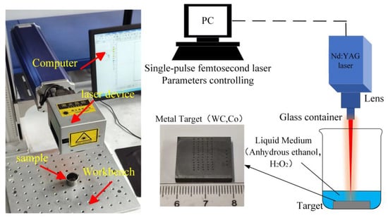
Figure 1.
Liquid-phase laser ablation experimental equipment and process schematic diagram.
2.3. Experiment Scheme
The hardness testing was performed using the HVS-1000AT/EOS100B automatic micro-Vickers hardness testing system(Bellemin Industrial Technology, Yantai City, China). A load of 10 N was applied to the surface of WC-Co cemented carbide specimens. At specific locations within the sample area, three measurements were taken per test to calculate an average value. This test procedure was repeated for three separate sets to ensure the reliability of the hardness measurements. Figure 2 illustrates the hardness measurement points within the ablation pits. Along the depth of the pit, the regions affected by laser ablation were divided into three influence zones, with adjacent zones separated by 100 μm. Within each of these three influence zones, testing points were selected, and each measurement point within a zone was spaced 50 μm apart.

Figure 2.
Schematic diagram of hardness test for textured ablation.
3. Results and Discussions
3.1. Effect of Laser Ablation Times on Hardness
3.1.1. Hardness Distribution of Laser-Ablated Points Textured in a Liquid-Phase Environment
Figure 3 presents the hardness distribution curves for laser-ablated point textures on WC-Co cemented carbide. As the number of laser ablations increases, the surface hardness of the point textures rises correspondingly. After 14 ablations, the hardness peaks at 2800 HV, representing a 51%–56% increase in Vickers hardness over the substrate. Notably, for single laser ablation, the Vickers hardness at the pit surface exhibits a distinct hardness profile: lower values at the pit base and higher values along its sidewalls. The hardness evolution is divided into six stages for discussion, as shown in Table 1, with Stage 1 showing minimal hardness variation among textured points at identical pass counts, while Stage 3 displays maximal variation.
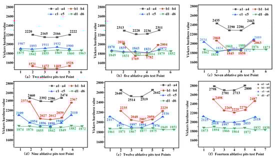
Figure 3.
Hardness distribution curve of point texture by laser ablation.

Table 1.
Evolution of Surface Hardness Ratios During Processing Stages.
Figure 3 illustrates the microhardness evolution of the laser-ablated workpiece. The Vickers hardness of the untreated cemented carbide substrate is approximately 1800 HV, whereas laser ablation generates a molten layer and hardened layer, resulting in elevated surface hardness compared with non-ablated regions. The hardness distribution displays a symmetrical profile along the ablation centerline, characterized by higher values at peripheries and lower values at the center. The depth of the hardness-affected zone progressively increases with the number of ablations, with Zone intensity ranking: a > b > c. After 14 ablations, Zone a reaches peak hardness (2800 HV). While Zone d, distal to the ablation center, maintains hardness comparable to the substrate (1800–1900 HV).
3.1.2. Changes in the Depth Direction of Laser Ablation Point Texture in a Liquid Phase Environment
As shown in Figure 4, this is a hardness curve diagram of texture along the depth direction. By analyzing the changes in cross-sectional hardness measured at different angles under various ablation times, it is divided into six stages:

Figure 4.
Hardness profile along depth direction of the weave profile.
Stage 1: After two liquid-phase laser ablations, the hardness exhibits a three-stage change along the depth direction, characterized by a “decrease-increase-decrease” pattern. The hardness at a–c shows a sharp decrease followed by a sharp increase, with the maximum decrease reaching 32.17% and the maximum increase reaching 30.09%; Stage 2: After 5 liquid-phase laser ablations, the measured hardness along the 30° direction shows a continuous decreasing trend, while the hardness changes along the 60° and 90° directions first decrease and then increase, eventually stabilizing. The a–b hardness exhibits a sharp decrease, with the maximum decrease reaching 20.6%; Third stage: After seven liquid-phase laser ablations, the hardness along the 30° direction showed two rapid, phased decreases with an intermediate plateau period, while the hardness along the 60° and 90° directions first decreased rapidly and then stabilized. The a–b hardness decreased sharply, with the maximum decrease reaching 19.43%; Fourth stage: After 9 liquid-phase laser ablation treatments, the hardness along the depth direction continued to decrease and eventually stabilized, with the fastest decrease in the a–b region reaching 15.26%; Fifth stage: After 12 liquid-phase laser ablations, the hardness decreased uniformly along the depth direction and stabilized in the d region; Sixth stage: After 14 liquid-phase laser ablations, the hardness decreased uniformly and steadily along the depth direction, with the most consistent distribution of the decrease.
3.1.3. Effect of the Number of Laser Ablations on Hardness in Different Zones of Point Textures
- 1.
- Hardness evolution in Zone a with laser ablations
Figure 5a shows the hardness evolution in Zone a with the number of laser ablations. It is evident that hardness continuously increases with the number of ablations. In Zone a, the hardness distributions of a1 and a4, as well as a2 and a3, exhibit symmetrical distribution about the pit centerline, with higher hardness at peripheries than at the center. As the number of ablations increases, Figure 5b reveals progressive convergence of the a1–a4 and a2–a3 hardness curves. The average hardness in Zone a demonstrates a steady upward trend with ablation times, with a 28.05% increase in average hardness observed after 14 ablations compared with the first ablation.
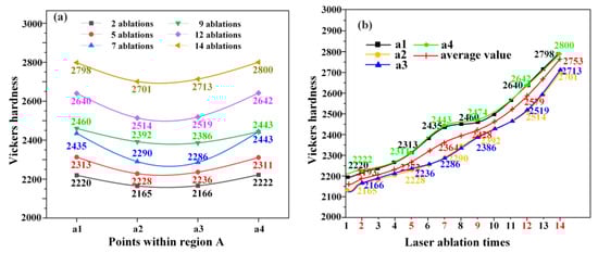
Figure 5.
Hardness variation curve of Zone a with ablation times. (a) Hardness evolution at the different position points, (b) Hardness evolution at the same position point.
- 2.
- Hardness evolution in Zone b with laser ablations
Figure 6a presents the hardness variation in Zone b with laser ablation times. Initial softening occurs at 2 ablations, where hardness dips below substrate levels. Subsequently, the hardness gradually increases, there is a slower rate of growth observed at 9–12 ablations with marginal periphery hardness decline. Throughout this process, Zone b maintains symmetrical hardness distribution about the pit centerline, exhibiting higher periphery values than centerline values.
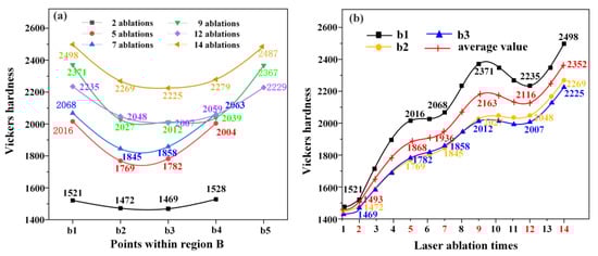
Figure 6.
Hardness variation curve of Zone b with ablation times. (a) Hardness evolution at the different position points, (b) Hardness evolution at the same position point.
Figure 6b reveals a multistage hardness evolution in subzone b1: an initial increase followed by a decline and subsequent recovery. Between 9–12 ablations, hardness decreased by 5.74%. Throughout ablations 1–14, Zone b exhibited sub-substrate hardness during ablations 1–4, attributed to cobalt carbide formation that reduced initial hardness. By the 14th ablation, hardness increased by 66.53% compared with the first ablation. Figure 5b further reveals that the hardness curves for b3 and b2 exhibit similar trends: both rise steadily initially, then stabilization plateau, and finally rise. The average hardness of region b demonstrates a gradual upward trend with the increase in the number of ablations. The hardness increases during the 1–5, 7–9, and 12–14 times, while stability with fluctuations is observed during the 5–7 and 10–12 times. During the fluctuation stage, the hardness value increases more slowly and may even experience a slight decrease.
- 3.
- Hardness evolution in Zone c with laser ablations
Figure 7a depicts the hardness evolution in Zone c with the number of laser ablation times. It is observed that, with the increase of the ablation times, the hardness value initially decreases followed by sustained increase. Zone c maintains symmetrical hardness distribution about the pit centerline, with periphery hardness exceeding centerline values.
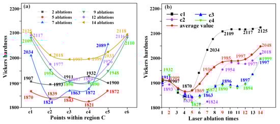
Figure 7.
Hardness variation curve of Zone c with ablation times. (a) Hardness evolution at the different position points, (b) Hardness evolution at the same position point.
As shown in Figure 7b, with the increase of ablation times, the hardness of Zone c1 initially decreases, then increases sharply, and finally stabilizes. From 1 to 4 ablation, the hardness decreases by 4.56%, followed by a sharp increase of 14.49% from 6 to 10 ablation, and then stabilizes. By the 14th ablation, the hardness in Zone c1 has increased by 11.20% compared with the first ablation. In Zone c2, the hardness initially decreases, then undergoes a sharp rise, followed by stable fluctuations, and finally a slow increase. The hardness drops by 3.66% from 1 to 6 ablation, increases sharply by 8.55% from 7 to 10 ablation, then stabilizes, and rises slowly by 2.07% from 12 to 14 ablation. By the 14th ablation, the hardness in Zone c2 has increased by 6.6% relative to the first ablation. And Zone c3 and c4 display similar hardness trends, with an initial decrease followed by a gradual increase. Meanwhile, the hardness decreases by 5.75% from 1 to 5 ablation and increases by 9.77% from the 5th to the 14th ablation. The average hardness in Zone c exhibits a trend of initial decrease followed by a gradual increase with increasing ablation times. The average hardness decreases by 3.56% from 1 to 5 ablation and increases by 7.28% at the 14th ablation compared with the first ablation.
- 4.
- Hardness evolution in Zone d with laser ablations
Figure 8 shows the hardness evolution in Zone d with the number of laser ablation, and it can be seen that with the increase of ablation times, the hardness value fluctuates within the range of 1800–1900 HV, consistently approximating substrate levels, and remains largely unaffected by laser ablation.
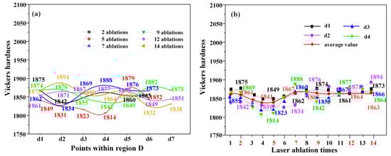
Figure 8.
Hardness variation curve of Zone d with ablation times. (a) Hardness evolution at the different position points, (b) Hardness evolution a at the same position point.
3.1.4. Effect of the Number of Laser Ablations on the Hardness of the Point Texture Depth Direction
- 1.
- Effect of the number of laser ablations on the hardness of the position point in the 30° depth direction
Figure 9a depicts the hardness evolution at 30° radial positions versus ablation times. After 2 ablations, Zone b1 exhibits sub-substrate hardness, signifying pronounced softening. Along the 30° direction, hardness increases cumulatively with ablations, though the enhancement magnitude decays radially from the ablation centerline. Data from 5th to 14th ablation, confirm progressive hardness reduction with increasing radial distance. With the increase of depth, its hardness shows a linear decreasing trend. These results demonstrate that laser ablation enhances cemented carbide hardness, with enhancement intensity scaling inversely to distance from the ablation site.
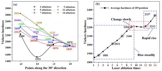
Figure 9.
Hardness of 30° position with the number of laser ablations. (a) Hardness evolution in the 30° direction, (b) Average hardness of 30° position.
Figure 9b shows the evolution of average hardness at 30° radial positions versus ablations. Along the 30° axis, hardness increases progressively during ablations 1–9, exhibits moderated growth at ablations 9–12, and undergoes accelerated enhancement at ablations 12–14. The net hardness gain after 14 ablations reaches 26.32% relative to the first ablation, with the terminal phase (ablations 12–14) alone contributing a 5.6% increase, accounting for 21.3% of the total gain.
- 2.
- Effect of the number of laser ablations on the hardness of the position point in the 60° depth direction
Figure 10a presents the hardness evolution at 60° radial positions versus ablation times. Zone b2 exhibits sub-substrate hardness after 2 and 5 ablations, confirming pronounced softening. Along the 60° axis, hardness increases overall occur with progressive passes. However, the enhancement magnitude decays radially from the ablation centerline. Data from ablations 7–14 demonstrate that progressive hardness reduction with increasing radial distance. As the depth increases, the decrease in hardness gradually slows down and eventually approaches the hardness of the matrix. These results establish that laser ablation enhances cemented carbide hardness, with enhancement intensity scaling inversely to distance from the ablation site.

Figure 10.
Hardness of 60° position with the number of laser ablations. (a) Hardness evolution in the 60° direction, (b) Average hardness of 60° position.
Figure 10b depicts the evolution of average hardness at 60° radial positions with laser ablation times. It can be seen that along the 60° axis, hardness progresses through three distinct phases: the Steady increase during ablations 1–7, the Rapid surges at ablations 7–9 (+5.85%) and ablations 12–14 (+5.71%), and Moderated change during ablations 9–12. Compared with the first ablation, the average hardness after 14 ablations reaches 21.81%. The two surge ablations collectively account for 52.9% of the total enhancement.
- 3.
- Effect of the number of laser ablations on the hardness of the position point in the 90° depth direction
Figure 11a depicts the hardness evolution at 90° radial positions versus laser ablation times. With the increase of depth, the overall hardness shows a decreasing trend. However, for the 2nd to 7th ablations, the hardness of the b3–c3 region increases as it moves away from the ablation center. Zone b3 exhibits sub-substrate hardness after 2nd and 5th ablations, indicating significant softening. While cumulative hardening occurs with progressive ablations; the enhancement magnitude decays radially from the ablation centerline. Data from ablations 5–14 further demonstrate progressive hardness reduction with increasing radial distance.

Figure 11.
Hardness of 90° position with the number of laser ablations. (a) Hardness evolution in the 90° direction, (b) Average hardness of 90° position.
Figure 11b presents the evolution of average hardness at 90° radial positions versus the number of laser ablations. Along the 90° axis, hardness progresses through three distinct phases: Steady increase during ablations 1–9, Moderated change at ablations 9–12, Rapid surge at ablations 12–14. The average hardness after 14 ablations has improved by 20.21% compared with the first ablation.
- 4.
- Effect of the number of laser ablations on the hardness of the position points in each direction
Figure 12 compares angular hardness evolution versus ablation times across 30°, 60°, and 90° radial positions. Three unified phase behaviors emerge: gradually increasing during ablations 1–7 (all angles), Moderated change at ablations 9–12 (all angles), Terminal acceleration at ablations 12–14 (all angles). Among the angles, the 30° orientation achieves the highest average hardness and the greatest overall increase, rising by 26.32% to reach 2337 HV. During terminal acceleration (ablations 12–14), the 90° orientation exhibits the most rapid surge with hardness rising by 5.82%.

Figure 12.
Hardness variation curve with laser ablation times for position points at different angles.
3.2. Phase Analysis of Ablation Pits in a Liquid Phase Environment
3.2.1. Effect of Laser Ablation Times on Phase Volume Fraction and Distribution
Figure 13 presents the XRD phase analysis of cross-sectional affected zones in liquid-phase ablated cemented carbide. After 2–5 laser ablations, the phase components include carbon (C), tungsten carbide (WC), W2C, and cobalt carbide (Co2C). Compared with the unablated substrate, laser ablation generates W2C and Co2C, confirming laser-induced phase transformations. After 7 to 14 ablations, the phase components include C, WC, and W2C, with Co2C disappearing under prolonged high-temperature ablation compared with 2–5 ablations.
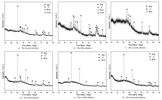
Figure 13.
XRD spectrum of WC-Cocemented carbide from liquid phase laser ablation.
Figure 14 illustrates the evolution of phase volume fractions versus laser ablation times. Initially, the WC content decreases from 91.2% (unablated) to 53.7%, then gradually recovers, stabilizing at ablations 12–14. Cobalt (Co) presents only in unabated state, constituting 8.8% of the material. W2C forms through physicochemical reactions, increasing progressively with ablations. Its high hardness directly contributes to overall hardening. Co2C appears at the initial ablation and is further decomposed into finer Co with increased laser energy, which improves the cemented carbide’ s hardness. C declines steadily to 1% with the number of ablations, promoting the combination of W and C and bulk material stabilization.
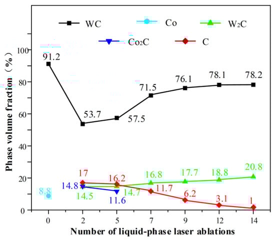
Figure 14.
Curve of physical phase volume fraction with the number of ablations.
3.2.2. Effect of Laser Ablation Times on Grain Size and Dislocation Density
The XRD spectrum of the liquid phase ablation point texture impact zone was analyzed. The grain size D was calculated by Equations (1)–(3), and the dislocation density was calculated.
D represents the average crystallite size (nm), k is Scherrer constant (0.89), β is FWHM (in radians), and θ is peak position (in radians). Additionally, the value of k varies between 0.8 and 1.2 (with a typical value of 0.9) [19,20].
is the dislocation density and is the microstrain.
Figure 15 compares grain structures and dislocation density after 2 and 14 laser ablations. It is evident that after 14 ablations, reduced fluctuation ranges in grain size and dislocation and a more uniform distribution compared with 2 ablations, indicating greater stability. XRD phase analysis reveals that the material produced after 2 ablations differs from that produced after 14 ablations. The initial products from 2 ablations include carbon, tungsten carbide, ditungsten carbide, and cobalt carbide, while the products after 14 ablations include carbon, tungsten carbide, and ditungsten carbide, with cobalt carbide missing. The result suggests that cobalt, present in a lower content compared with tungsten, partially reacts under high-temperature processing. As the laser energy increases, tungsten grains become further refined and more uniformly distributed, better adhesion and thereby improving the hardness of the material.
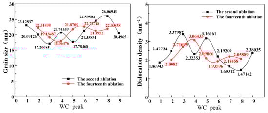
Figure 15.
Grain size and dislocation density of 2nd and 14th ablations.
3.3. Metallographic Analysis of Pits in the Liquid Phase Environment Ablation Point Texture
As shown in Figure 16, the metallographic microstructures of different regions are compared after 2 and 14 liquid-phase laser ablation treatments. A–D represent the microstructures of different regions under the same number of ablations. According to the metallographic microstructure atlas of metallic materials, the white material is identified as the WC (α) phase, while the dark (dark-colored) material is the binder Co phase (β). As shown in Figure 16a, the β phase is distinctly distributed in Region A. In the upper half, the α phase and β phase alternate in layers, forming a compact structure. Under high-temperature conditions, the α phase undergoes gradual decarburization, resulting in severe depletion of the α phase. The β phase, as a binder, enhances the hardness of Region A; In Figure 16b,c, cluster-like β phase and striated microcracks are observed in regions B and C, with the β phase aggregating near the striated microcracks. This is because over 50% of cracks in cemented carbides propagate through WC interfaces, and there is a single layer of Co binder between carbide grains, i.e., the β phase. In Figure 16d, no microcracks were observed in region D, the temperature did not reach the phase transformation threshold, and its metallographic microstructure was basically the same as that of the matrix.
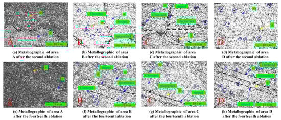
Figure 16.
Comparison of metallographic between the second and fourteenth liquid phase laser ablation.
When the ablation time reached 14 times, as shown in Figure 16e, it was observed that α and β fused together in region A, covering a wide range, distributed evenly, and extremely abundant, and its hardness gradually increased with the fusion process of α and β phases. In Figure 16f,g, microcracks are clearly visible, and the β phase is partially melted but not completely lost, while the α phase undergoes refinement; in Figure 16h, microcracks are less severe than in other regions, and the β phase is less abundant.
3.4. Mechanism Model of WC-CO Hardness Evolution by Liquid-Phase Laser Ablation
Figure 17 presents a six-stage mechanism model for point-textured hardness evolution in WC-Co cemented carbide during liquid-phase laser ablation. “H” represents the ablation depth of the laser, which is the distance from the material surface to the deepest part of the pit. At Stage 1, at ablations 2, limited energy input confines phase transformations (W2C, Co2C, WC, C formation) within 100 μm of ablation center. Minimal hardness enhancement. At Stage 2, laser energy absorption induces thermal expansion, extending affected zone to 200 μm radially after ablations 5. The hardness distribution becomes uneven, with a noticeable reduction in cobalt carbide content as matrix hardness increases. The third stage, number of ablations 7, the hardness-affected zone expands to 300 μm, exhibiting an uneven hardness distribution with higher values at the ends and lower in the center. Co2C disappears, while W2C and WC increase, and the hardness of the workpiece is greatly enhanced by the W2C produced by high-temperature ablation. The fourth stage, number of ablations 9, the affected zone extends downward to 386 μm. The continuous increase in W2C and WC raises the hardness, C content begins to decrease, reducing impurity levels and further enhancing hardness. At Stage 5, number of ablations 12, maximum energy density achieved at 449 μm depth. The ongoing increase in W2C and WC improves hardness, while C reduction impurity levels, thus enhancing the hardness of the affected area. The sixth stage, number of ablations 14, Molten pool stabilizes under recoil pressure, surface tension, gravity balance. The plasma generated by ablation causes a shielding effect [21], leading to the accumulation of coating material and no significant effect on the molten pool, achieving dynamic balance. The affected area reaches 407 μm, and the workpiece maintains dynamic equilibrium as it absorbs energy. W2C and WC continue to increase, while C decreases, resulting in maximum overall hardness. Notably, WC is a crucial factor affecting the hardness of the cemented carbide, with its grain size and dislocation density becoming more uniformly distributed, grain refinement, and closer bonding.

Figure 17.
Mechanism model of the evolution of WC-Co cemented carbide point texture hardness with liquid-phase laser ablation times.
4. Conclusions
This study examines the influence of liquid-phase laser ablation times on the hardness evolution of WC-Co cemented carbide by analyzing phase transformations, grain refinement effects, and their combined contributions to hardness enhancement. A hardness evolution model for WC-Co cemented carbide under liquid-phase laser ablation conditions is proposed. The key findings are summarized as follows:
- (1)
- Single-pass liquid-phase laser ablation produces textured surfaces characterized by symmetrical hardness profiles, where the periphery exhibits higher hardness values compared to the centerline. Along the depth axis, hardness demonstrates a gradient pattern, with elevated values observed near the surface and at the bottom, decreasing toward intermediate depths. Importantly, hardness decreases radially with increasing distance from the ablation center. During the ablation process from 1 to 14 pulses, the hardness in zones a, b, and c generally increases with the number of ablation times, whereas the hardness in zone d, located farther from the ablation center, approaches that of the original substrate. As the number of ablation times increases, overall hardness shows an upward trend, with the average hardness in the 30° orientation increasing rapidly and ultimately achieving a 26.32% improvement compared to the substrate.
- (2)
- Following liquid-phase laser ablation (2–5 times), the material consists of phases C, WC, W2C, and Co2C. Beyond six ablation times, the phase composition transitions to C, WC, and W2C. Throughout this process, WC grains undergo progressive refinement, accompanied by a more uniform dislocation density distribution. The enhancement of grain boundary cohesion and binder phase densification further contributes to increased hardness.
- (3)
- With increasing ablation times, WC grains become increasingly refined, leading to a higher grain boundary density that hinders dislocation movement. In terms of phase transformation, WC undergoes decarburization at elevated local temperatures, forming high-hardness W2C. Meanwhile, transitional phases such as Co2C decompose into finer Co particles during continuous ablation, strengthening the bonding phase and resulting in a gradual increase in hardness from the ablation center toward the periphery.
- (4)
- A model describing the hardness evolution mechanism of point-textured WC-Co cemented carbide under liquid-phase laser ablation was developed. As the number of ablation times increases, the hardness of the workpiece progressively increases. During the first seven ablation times, continuous heat absorption promotes phase transformations, expanding the hardness-affected zone both radially outward and axially downward. After nine ablation times, the affected zone stabilizes at approximately 300 μm in depth. Within this zone, the quantities of WC and W2C continue to increase, further enhancing the hardness of the affected region. The carbon content reaches its minimum after 14 ablation times, indicating the lowest level of impurities and resulting in maximum hardness.
Author Contributions
Conceptualization and validation, X.G.; writing—original draft preparation and visualization, Y.D. (Yi Ding); formal analysis and methodology, Y.F.; resources, K.Z.; supervision, X.G.; investigation, J.X.; writing—review and editing, Y.D. (Yuchen Du); project administration, S.W. All authors have read and agreed to the published version of the manuscript.
Funding
This research was funded by National Natural Science Foundation of China, grant number 12202167.
Institutional Review Board Statement
Not applicable.
Informed Consent Statement
Not applicable.
Data Availability Statement
Data are contained within the article.
Acknowledgments
The authors are grateful to the School of Mechanical Engineering, Jiangsu University of Science and Technology for providing equipment support.
Conflicts of Interest
The authors declare no conflicts of interest.
References
- Chu, C.; Zhang, Q.; Zhuo, H.; Zhang, Z.; Zhu, Y.; Fu, Y. Investigation on the Ablation Behavior of Cemented Tungsten Carbide by a Nanosecond UV Laser. J. Manuf. Process. 2021, 71, 461–471. [Google Scholar] [CrossRef]
- Fang, S.; Llanes, L.; Bähre, D. Laser Surface Texturing of a WC-CoNi Cemented Carbide Grade: Surface Topography Design for Honing Application. Tribol. Int. 2018, 122, 236–245. [Google Scholar] [CrossRef]
- Li, W.; Duan, H.; Li, G.; Zhan, S.; Zhang, W.; Ma, L. Research Progress in Controlling Material Tribological Properties by Laser Surface Texture Technology. Surf. Technol. 2024, 53, 85–101+157. [Google Scholar] [CrossRef]
- Deng, J.X.; Song, W.L.; Zhang, H.; Zhao, J.L. Performance of PVD MoS2/Zr-Coated Carbide in Cutting Processes. Int. J. Mach. Tools Manuf. 2008, 48, 1546–1552. [Google Scholar] [CrossRef]
- Li, W.; Yan, S.; Zhang, L. Effects of Surface Shot Peening Strengthening on Fatigue Property of TC11 Titanium Alloy. Surf. Technol. 2017, 46, 172–176. [Google Scholar] [CrossRef]
- Ren, X.; Zou, H.; Diao, Q.; Wang, C.; Wang, Y.; Li, H.; Sui, T.; Lin, B.; Yan, S. Surface Modification Technologies for Enhancing the Tribological Properties of Cemented Carbides: A Review. Tribol. Int. 2023, 180, 108257. [Google Scholar] [CrossRef]
- Dolinšek, S.; Šuštaršič, B.; Kopač, J. Wear Mechanisms of Cutting Tools in High-Speed Cutting Processes. Wear 2001, 250, 349–356. [Google Scholar] [CrossRef]
- Fan, Y.; Zhao, K.; Hao, M.; Xia, J.; Guan, X.; Liu, F. An Analysis of the Morphology Evolution of YG8 Cemented Carbide by Laser Ablation in the Liquid Phase. Coatings 2023, 13, 2061. [Google Scholar] [CrossRef]
- Zhang, Z.; Lu, W.; He, Y.; Zhou, G. Research on Optimal Laser Texture Parameters about Antifriction Characteristics of Cemented Carbide Surface. Int. J. Refract. Met. Hard Mater. 2019, 82, 287–296. [Google Scholar] [CrossRef]
- Maharjan, N.; Zhou, W.; Zhou, Y.; Guan, Y.; Wu, N. Comparative Study of Laser Surface Hardening of 50CrMo4 Steel Using Continuous—Wave Laser and Pulsed Lasers with Ms, Ns, Ps and Fs Pulse Duration. Surf. Coat. Technol. 2019, 366, 311–320. [Google Scholar] [CrossRef]
- Zimmermann, M.; Kirsch, B.; Kang, Y.; Herrmann, T.; Aurich, J.C. Influence of the Laser Parameters on the Cutting Edge Preparation and the Performance of Cemented Carbide Indexable Inserts. J. Manuf. Process. 2020, 58, 845–856. [Google Scholar] [CrossRef]
- Pan, X.; Zhou, L.; Hu, D.; He, W.; Liu, P.; Yu, Z.; Liang, X. Superior Wear Resistance in Cast Aluminum Alloy via Femtosecond Laser Induced Periodic Surface Structures and Surface Hardening Layer. Appl. Surf. Sci. 2023, 636, 157866. [Google Scholar] [CrossRef]
- Temmler, A.; Braun, K.; Uluz, E. Heat Accumulation and Surface Roughness Evolution in CO2 Nanosecond Laser Ablation of Quartz Glass. Opt. Laser Technol. 2021, 144, 107426. [Google Scholar] [CrossRef]
- Fan, Y.; Li, B.; Lu, J.; Xia, J.; Liu, F.; Qiu, X. Study on Morphology Evolution of GCr15 Steel by Nanosecond Laser Ablation. Chin. J. Lasers 2023, 50, 2002201. [Google Scholar] [CrossRef]
- Jing, X.; Wang, J.; Song, X.; Chen, Y.; Jaffery, S.H.I. A Comparative Investigation on Micro-Channel by Using Direct Laser Ablation and Liquid-Assisted Laser Ablation on Zirconia. Ceram. Int. 2023, 49, 31871–31880. [Google Scholar] [CrossRef]
- Qiu, P.; Guo, Y.; Li, J.; Xu, S. Effect of Bubble Dynamic Behaviors on Machining Performance of Laser-Induced Microjet—Assisted Ablation. J. Manuf. Process. 2024, 120, 116–122. [Google Scholar] [CrossRef]
- Pang, M.; Zhai, S.; Feng, Q.; Zhang, Q.; Ma, L. Liquid-Phase Assisted Laser Preparation of Cemented Carbide Surface Textures and Study on Their Tribological Properties. Tribology 2022, 42, 1001–1011. [Google Scholar] [CrossRef]
- Wang, B.; Wang, Z.; Yin, Z.; Yuan, J. Wear Behavior of Ultrafine WC-Co Cemented Carbide End Mills during Milling of Inconel 718. Wear 2024, 546–547, 205359. [Google Scholar] [CrossRef]
- Zhang, Y. Study on the Milling Performance of Textured Ball-End Milling Cutter with Coating. Master’s Thesis, Jiangsu University, Zhenjiang, China, 2020. [Google Scholar] [CrossRef]
- Sugihara, T.; Enomoto, T. Improving Anti-Adhesion in Aluminum Alloy Cutting by Micro Stripe Texture. Precis. Eng. 2012, 36, 229–237. [Google Scholar] [CrossRef]
- Zhai, Z.; Wang, W.; Mei, X.; Wang, K.; Wang, F.; Pan, A. Effect of Temporal Control of Air/Water Environment on Laser Drilling of Nickel-Based Alloy with Thermal Barrier Coatings. Int. J. Adv. Manuf. Technol. 2018, 97, 3395–3405. [Google Scholar] [CrossRef]
Disclaimer/Publisher’s Note: The statements, opinions and data contained in all publications are solely those of the individual author(s) and contributor(s) and not of MDPI and/or the editor(s). MDPI and/or the editor(s) disclaim responsibility for any injury to people or property resulting from any ideas, methods, instructions or products referred to in the content. |
© 2025 by the authors. Licensee MDPI, Basel, Switzerland. This article is an open access article distributed under the terms and conditions of the Creative Commons Attribution (CC BY) license (https://creativecommons.org/licenses/by/4.0/).