Article

Effect of Cerium Nitrate Content on the Performance of Ce(III)/CF/BN/EPN Heat Exchanger Coatings

1
Sinopec Southwest China Petroleum Bureau, Chengdu 610095, China
2
Sinopec Key Laboratory of Development Technology of Sour Natural Gas Fields, Chengdu 610095, China
3
Petroleum Engineering School, Southwest Petroleum University, Chengdu 610500, China
4
State Key Laboratory of Oil and Gas Reservoir Geology and Exploitation, Southwest Petroleum University, Chengdu 610500, China
*
Authors to whom correspondence should be addressed.
Coatings 2025, 15(7), 818; https://doi.org/10.3390/coatings15070818
Submission received: 11 June 2025 / Revised: 9 July 2025 / Accepted: 10 July 2025 / Published: 13 July 2025

Abstract

This study investigates the influence of cerium nitrate (Ce(NO3)3·6H2O) content on the performance of Ce(III)/CF/BN/EPN coatings intended for heat exchangers. A series of Ce(III)/carbon fibre (CF)/boron nitride (BN)/epoxy phenolic (EPN) coatings are fabricated with varying concentrations of Ce(NO3)3·6H2O. The results of SEM and EDS show that the dissolution of cerium nitrate in acetone due to the particulate form causes it to be distributed in a diffuse state in the coating. This diffuse distribution does not significantly alter the porosity or structural morphology of the coating. With the increase in cerium nitrate content, both the EIS test results and mechanical damage tests indicate a progressive improvement in the corrosion resistance and self-healing properties of the coatings, while the thermal conductivity (TC) remains largely unaffected. The Ce in the coating reacts with the water molecules penetrating into the coating to generate Ce2O3 and CeO2 with protective properties to fill the permeable pores inside the coating or to form a passivation film at the damaged metal–coating interface, which enhances the anticorrosive and self-repairing properties of the coating. However, the incorporation of Ce(NO3)3·6H2O does not change the distribution structure of the filler inside the coating. As a result, the phonon propagation path, rate, and distance remain unchanged, leading to negligible variation in the thermal conductivity. Therefore, at a cerium nitrate content of 2.5 wt%, the coating exhibits the best overall performance, characterised by a |Z|0.1Hz value of 6.08 × 10⁹ Ω·cm2 and a thermal conductivity of approximately 1.4 W/(m·K).

1. Introduction

Oil and gas, two common fossil fuels, remain among the most critical energy sources supporting modern societal development [1]. Following the extraction of oil and gas fluids from the wellhead and their entry into the surface gathering system, the process of heating through a heat exchanger is of paramount importance in the context of oil and gas production [2]. Carbon steel is widely used in the fabrication of heat exchangers due to its low cost and excellent thermal conductivity. However, the corrosion resistance of carbon steel is inadequate, and the issue of corrosion is particularly salient during the process of service use, thereby posing a grave threat to the safe and stable operation of oil and gas fields [3]. Coating is a widely adopted method for protecting equipment and pipelines in oil and gas fields from corrosion, including applications involving heat exchangers. Its advantages include its low cost, the simplicity of its process, and the stability of its effect [4]. At present, the TC of commercial heat exchanger coatings (TC~0.4 W/(m·K)) is generally weak, which limits their heat transfer efficiency and leads to substantial energy losses [5]. In contrast, enhancing the TC of the coating reduces the heat transfer resistance, thereby lowering the heat loss coefficient of the heat exchanger. When a coating of 0.3 W/(m·K) exists on the surface of the heat exchanger’s heat transfer system, the heat transfer loss of the heat exchanger is approximately 9%. However, when the TC of the coating is increased to 1.6 W/(m·K), the heat transfer coefficient loss is significantly reduced to about 1.4% [6]. Hence, enhancing the TC of coatings is of paramount importance for heat exchangers, as it promotes energy conservation, reduces carbon emissions, and enhances overall energy utilisation efficiency.
In recent years, driven by the “dual carbon” goals—carbon peaking and carbon neutrality—some scholars have recently carried out research and development on high-thermal-conductivity anti-corrosion coatings for heat exchangers. A primary strategy for enhancing the TC of such coatings involves the incorporation of a thermally conductive filler [7]. Yan et al. incorporated BN and CF into an EPN coating to fabricate a BN/CF/EPN coating. This coating was found to possess a TC of up to 1.4 W/(m·K), and a |Z|0.1Hz value of 2.03 × 10⁹ Ω·cm2 was achieved [8]. Pan et al. added tannic acid-modified BNNs to epoxy resin and prepared the resulting M-BNNs/EP coating, achieving a TC of 0.6 W/(m·K) and 105 Ω·cm2 at |Z|0.01Hz [9]. Xu et al. prepared a BN/G/Phe/ZP/EP composite coating by combining Phe-modified BN, G, and zinc phosphate with EP. The resulting coating demonstrated a TC of 1.63 W/(m·K) and an impedance modulus |Z|0.01Hz of 1011 Ω·cm2 [6].
It has been determined that the long-term service conditions for heat exchanger coatings are a high temperature, high humidity, and near-neutral environment. These conditions contribute to an aggressive corrosive atmosphere, increasing the risk of coating degradation. It is acknowledged that during service, coatings inevitably experience localized damage, infiltration, and other forms of degradation that allow corrosive media to reach the underlying metal substrate, ultimately leading to corrosion [10]. The addition of a corrosion inhibitor to the coating can enhance its self-repairing properties and delay the onset of corrosion when the coating undergoes degradation [11]. It is evident that, in accordance with the active ingredient of the corrosion inhibitor, the inhibitor can be categorised into three distinct types: organic, inorganic, and composite [12]. It is evident that imidazoline, amine, organophosphorus, amide, and other compounds are organic corrosion inhibitors. These inhibitors possess the advantageous qualities of uniform film formation and a satisfactory corrosion inhibition effect [13]. However, in oil and gas fields, the working environment of the heat exchanger can reach temperatures in excess of 80 °C, thus creating a high-temperature caustic corrosion environment. The utilisation of organic corrosion inhibitors is contingent upon their high temperature sensitivity. Elevated temperatures in the environment have been shown to exert a substantial influence on the molecular structure or adsorption status of these inhibitors, consequently leading to a marked diminution in their efficacy as corrosion inhibitors [14]. Furthermore, inorganic corrosion inhibitors have been demonstrated to exhibit a broad temperature adaptation range [15]. In such instances, the employment of inorganic corrosion inhibitors as fillers emerges as a more appropriate alternative.
Ce(NO3)3·6H2O is a prevalent inorganic corrosion inhibitor, known for its excellent thermal stability and strong corrosion resistance. The substance under discussion has been demonstrated to possess the capacity to augment the corrosion resistance and self-repairing capabilities of coatings. Moghaddam et al. added cerium nitrate and tannic acid to an epoxy coating and found that this coating had a |Z|0.01Hz value exceeding 107 Ω·cm2 after 3 weeks of immersion in a 3.5 wt.% NaCl solution [16]. Danaee et al. prepared montmorillonite nano-epoxy coatings containing Ce3+ and found that the |Z|0.01Hz of the Ce3+ containing coatings could still reach 108 Ω·cm2 after 100 days of immersion [17]. In the work by Sehrish et al., 1% wt of benzotriazole (BTA)-modified cerium oxide-coated zinc oxide hybrid particles (CeO2@ZnO) were added to a polyolefin matrix, and they found that this coating could reach up to 1011 Ω·cm2 in a 3.5 wt.% NaCl solution at |Z|0.01Hz [18]. Ren et al. incorporated ethylene vinyl acetate (EVA) microspheres loaded with Ce(NO3)3 into an epoxy resin, and following the curing process at an elevated temperature, the coating exceeded 1010 Ω·cm2 in a 3.5 wt.% NaCl solution at |Z|0.01Hz [19].
In summary, this study has reviewed the current body of literature concerning high TC anti-corrosion coatings. However, the research has thus far focused on the dual objectives of TC and corrosion resistance, rather than on the self-repairing performance of the coating itself. The research has not yet considered the self-repairing performance of heat exchangers with high TC corrosion-resistant coatings. Based on the findings of our previous work, the OCF1.5–15 coating has demonstrated excellent TC and corrosion resistance [8].
In this study, Ce(NO3)3·6H2O was incorporated into the OCF1.5–15 coating to develop a novel heat exchanger coating (referred to as the Ce coating) that simultaneously exhibits a high TC, corrosion resistance, and self-healing capabilities. The objective is to investigate the influence of varying Ce(NO3)3·6H2O contents on the comprehensive performance of the coating.
The physical and chemical properties of cerium nitrate were characterised using a suite of analytical techniques, including X-ray diffraction (XRD), field emission scanning electron microscopy (FE-SEM), and energy-dispersive X-ray spectroscopy (EDS). The microstructure and elemental composition within the coating were subjected to rigorous testing using FE-SEM and EDS techniques. The TC test and electrochemical impedance spectroscopy (EIS) were utilised to assess the TC and anticorrosive properties of the Ce coating and to investigate the influence law of its content on the TC and anticorrosive properties of the coating. The surface of the coating was artificially broken using a utility knife, and the macroscopic morphology of the broken coating and the microscopic morphology of the metal at the broken place were observed by the visual inspection method and SEM to evaluate the self-repairing property of the Ce coating. Furthermore, X-ray photoelectron spectroscopy (XPS) was employed to analyse the elemental and chemical composition of the metal surface at the damaged site to investigate the self-repairing mechanism.

2. Experiment

2.1. Raw Materials

All materials and reagents utilised in this chapter were employed in their original state, without undergoing any additional treatment such as purification, as illustrated in Table 1.

2.2. Preparation of Ce Coating

The fillers employed in the preparation of the Ce coating were A-BNNS3, OCF1.5, and Ce(NO3)3·6H2O. Acetone was used as the diluent, and Ancamine 2280 served as the curing agent. These components were uniformly dispersed in the EPN resin through mechanical stirring to produce the Ce coating. The preparation process is illustrated in Figure 1. Among them, A-BNNS3 is composed of h-BNNs that have been modified by silanisation using 3-aminopropyltriethoxysilane (APTES) as the silane coupling agent. The mass ratio of APTES to h-BNNs is 3:1. The specific preparation method can be found in our team’s previous research paper [20]. OCF1.5 refers to raw carbon fibres that have been oxidised in an acid solution for 1.5 h. The oxidising solution consists of a 65% aqueous mixture of strong acids, with concentrated H2SO4 and HNO3 mixed in a volume ratio of 3:1. Our team’s pre-published paper contains a detailed methodology for the treatment of carbon fibre oxidation [8].
Initially, the mixer was used to rapidly disperse the EPN resin at 2000 rpm. In the subsequent step, the A-BNNS3 filler was gradually added to the EPN resin to minimise agglomeration. The filler was added incrementally in portions of approximately 0.2 g each time, until a total amount corresponding to 15 wt% of the EPN resin was reached. Following the complete addition of A-BNNS3, the mixture was stirred at 2000 rpm for an additional eight hours to ensure uniform dispersion of the filler within the resin matrix. Subsequently, OCF1.5 and Ce(NO3)3·6H2O were gradually added to the A-BNNS3/EPN resin mixture in multiple portions. The total amount of OCF1.5 added was 15% of the mass of the EPN resin. Then, the mixer was continuously stirred at 2000 rpm for 12 h to guarantee uniform dispersion of the fillers within the coating when both OCF and inorganic corrosion inhibitor fillers were added.
Next, an acetone diluent (10% by weight of EPN resin) was added to reduce the viscosity of the coating. Subsequently, Ancamine 2280 hardener (60% by weight of EPN resin) was added, and the mixture was stirred continuously at 500 rpm for 10 min. Finally, to eliminate air bubbles, the paint was degassed in a vacuum tank three times for ten minutes each. Ce coatings doped with different concentrations of Ce(NO3)3·6H2O were fabricated separately using this method. The coatings were designated based on their Ce(NO3)3·6H2O contents, which were set at 0.5 wt.%, 1.0 wt.%, 1.5 wt.%, 2.0 wt.%, and 2.5 wt.%, respectively. Accordingly, the samples were labelled Ce0.5, Ce1.0, Ce1.5, Ce2.0, and Ce2.5. A coating without the addition of Ce(NO3)3·6H2O served as the control group and was designated as OCF1.5–15.

2.3. Preparation of Ce Coating Characterisation Sample

The Ce coating was applied to the surface of a 20# steel plate (150 mm × 100 mm × 0.28 mm) using the scraping method to prepare specimens for corrosion resistance testing. Prior to coating, the steel substrate was thoroughly cleaned by sequential degreasing with ethanol and acetone. The coating was then uniformly applied to the surface of the steel plate using a 200 μm size squeegee. Finally, the coated samples were heated in an oven at 60 °C for 20 min to obtain a fully cured and dried coating.
The TC test samples of Ce coatings were prepared using the casting method. Firstly, the coating material was poured into silicone moulds with dimensions of φ32 mm × 20 mm. The filled moulds were then placed in an oven and cured at 60 °C for 60 min to ensure complete drying and solidification of the samples.

2.4. Material Characterisation and Performance Testing

The surface morphology of Ce(NO3)3·6H2O inorganic corrosion inhibitor and its dispersion within the coating were examined using FE-SEM (Aprea S HiVac, Thermo Fisher Scientific, Waltham, MA, USA). The elemental composition of Ce(NO3)3·6H2O was characterised by EDS (Aztec X-Max80, Oxford Instruments, Britain, UK). Additionally, the physical structure of Ce(NO3)3·6H2O inorganic corrosion inhibitor was analysed by XRD technique. The XRD analysis was conducted over a 2θ range of 10° to 60°, with a scanning speed of 1°/s.
The surface morphology and dispersion state of each filler in the Ce coatings were examined by FE-SEM, and the chemical elements on the surface of Ce coatings were analysed by EDS. XPS (K-Alpha, Thermo Scientific, Waltham, MA, USA) was employed to investigate the chemical composition of corrosion products formed on the metal substrate surface after coating damage. In the XPS analysis, all results were calibrated using the standard binding energy of C-C, 284.8 eV, as the calibration energy. The coating thickness gauge (DTG-D2, Shenzhen Hongda Instrument Equipment Co., Ltd.,Shenzhen, China) was used to complete the coating thickness test, guaranteeing a dry film thickness of 110 ± 10 μm in the area of the coating to be tested.
The TC of the coating was measured at 25 °C using a TC meter (DR-32JS, Nanjing Dazhan Testing Instrument Co., Ltd., Nanjing, China) based on the transient plane source (TPS) method.
The corrosion resistance of the coatings was evaluated using the electrochemical impedance spectroscopy (EIS). The environment for evaluating the corrosion resistance of the coatings was a 3.5 wt.% NaCl solution at 80 °C. The electrochemical tests were performed in a conventional three-electrode system. In the three-electrode system, the reference electrode is a saturated calomel electrode (SCE, Shanghai Ledon Industrial Co., Ltd., Shanghai, China), the auxiliary electrode is a graphite electrode, and the coated sample plate is the working electrode (exposure area of 6.15 cm2). EIS testing was accomplished by means of an electrochemical workstation (CS 350, CorrTest, Wuhan Corrtest Instruments Corp., Ltd., Wuhan, China). The EIS test can be performed when the open-circuit potential (OCP) fluctuates no more than 0.1 mV/min during the test. The EIS test was performed with a sinusoidal AC amplitude of 20 mV (vs. OCP) and a test frequency range of 10−1 to 105 Hz. The results of EIS were analysed and fitted using ZSimpWin software V3.6.
To evaluate the self-repairing performance of the coating under mechanical damage, artificial defects were introduced by creating cross-shaped scratches on the coating surface using a 0.3 mm utility knife. The damaged samples were then immersed in a 3.5 wt.% NaCl solution for 7 days to simulate a corrosive environment. Following immersion, the self-repairing behaviour of the coatings was assessed through macroscopic and microscopic observations of the damaged regions.

3. Results and Discussion

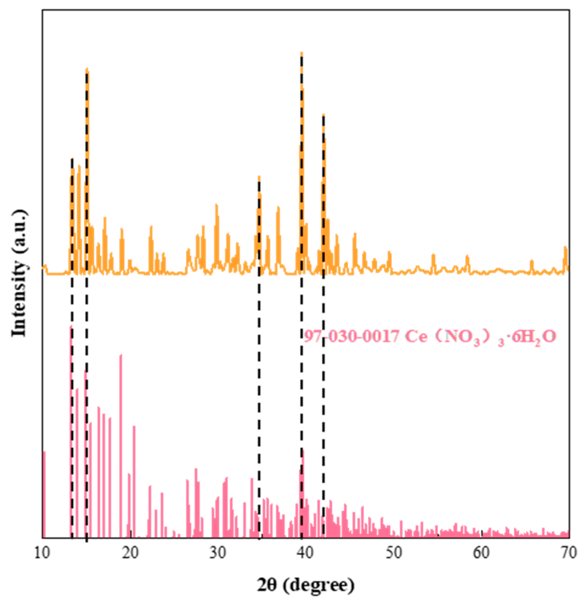
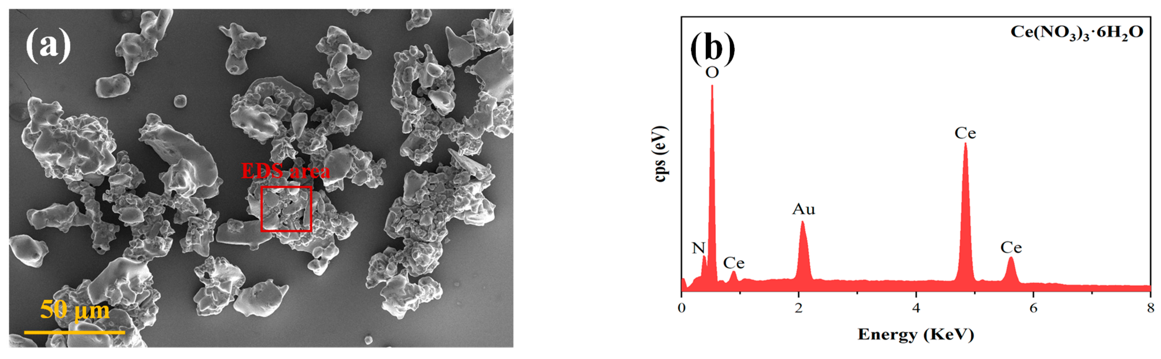
3.1. Characterisation of the Physical and Chemical Properties of Ce(NO3)3-6H2O

The XRD pattern confirms the high purity of the Ce(NO3)3·6H2O sample, showing no detectable impurities and matching well with the standard reference pattern (JCPDS No. 97-030-0017). Prominent diffraction peaks were observed at 14.1°, 14.9°, 39.6°, and 41.9°, corresponding to the (001), (011), (321), and (231) crystal planes, respectively.
The surface morphology of Ce(NO3)3·6H2O was analysed by FE-SEM, and the results are shown in Figure 2a. The cerium nitrate particles have an irregular massive morphology, with most of them having a rectangular morphology, and the average particle size is 30~50 μm. To determine the elemental composition of the cerium nitrate inorganic corrosion inhibitor, it was analysed by EDS spectroscopy, and the results are shown in Figure 2b. Cerium nitrate contains the elements N, O, and Ce. It can be concluded that the cerium nitrate does not have any impurity elements in it, indicating a high purity level of approximately 100%.

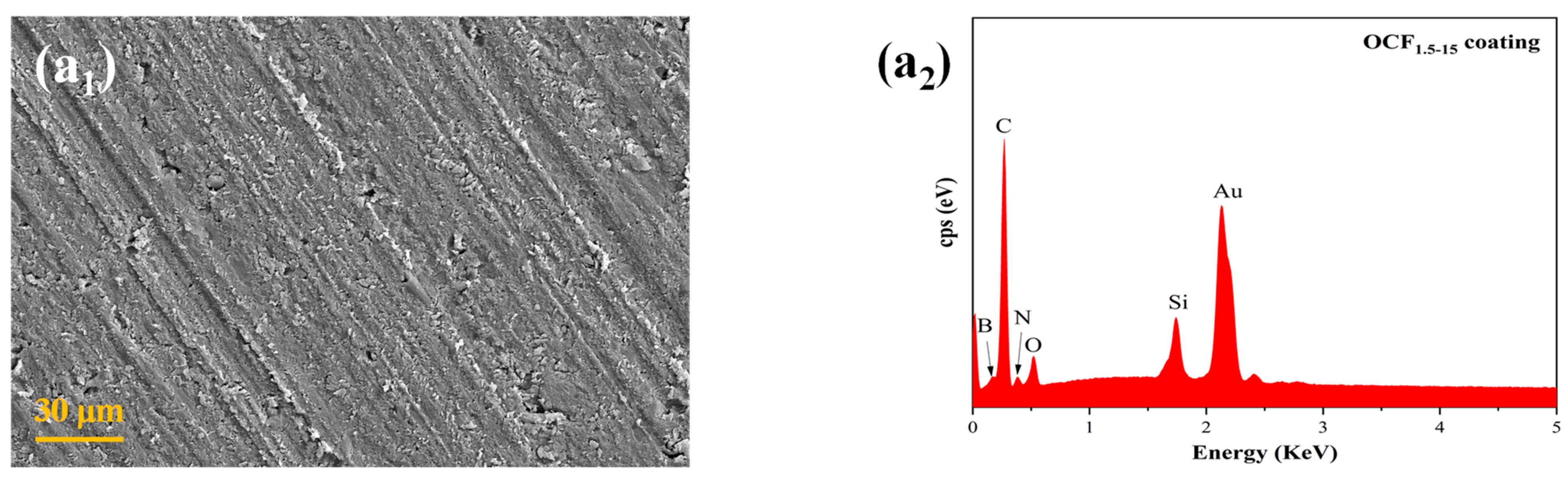
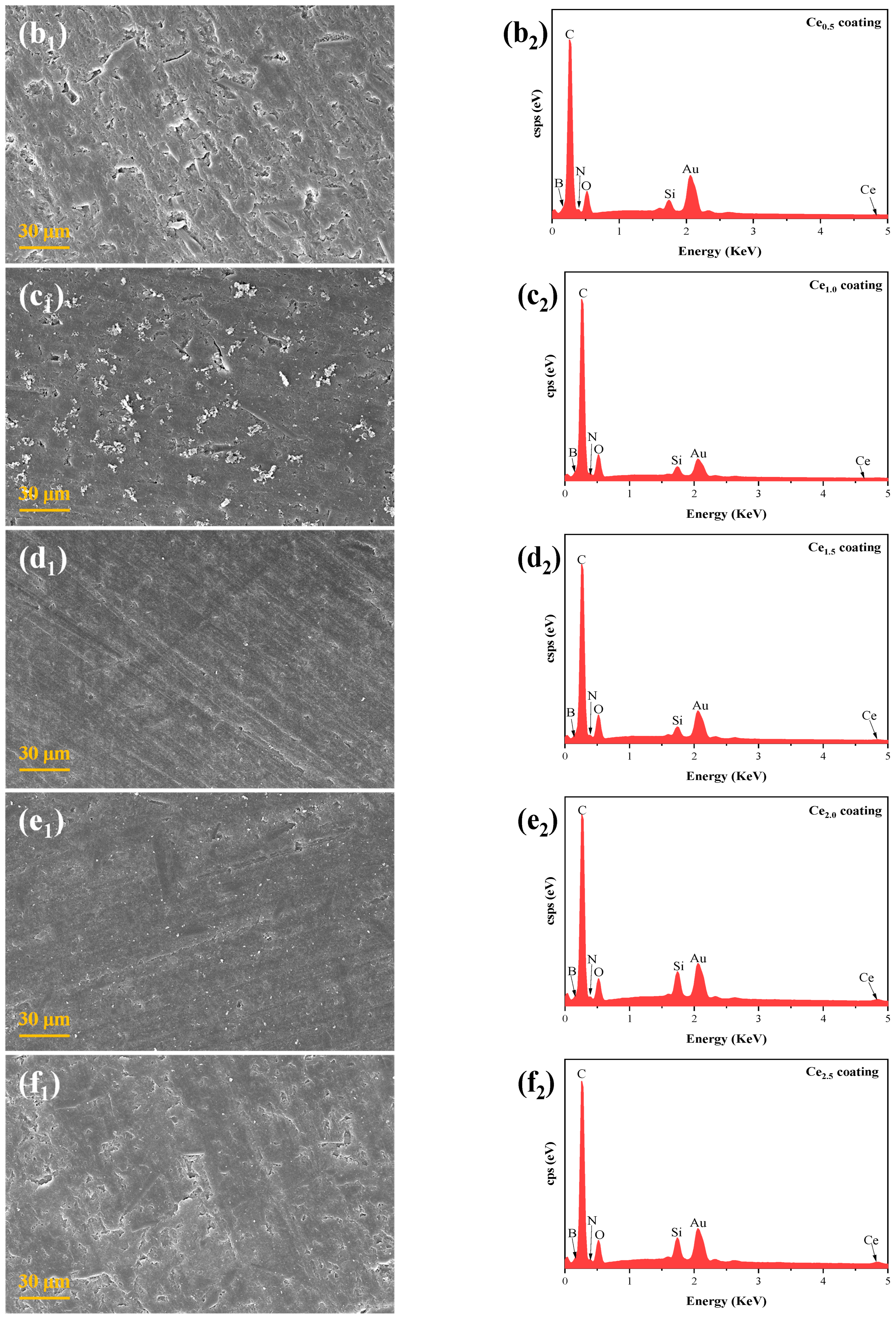
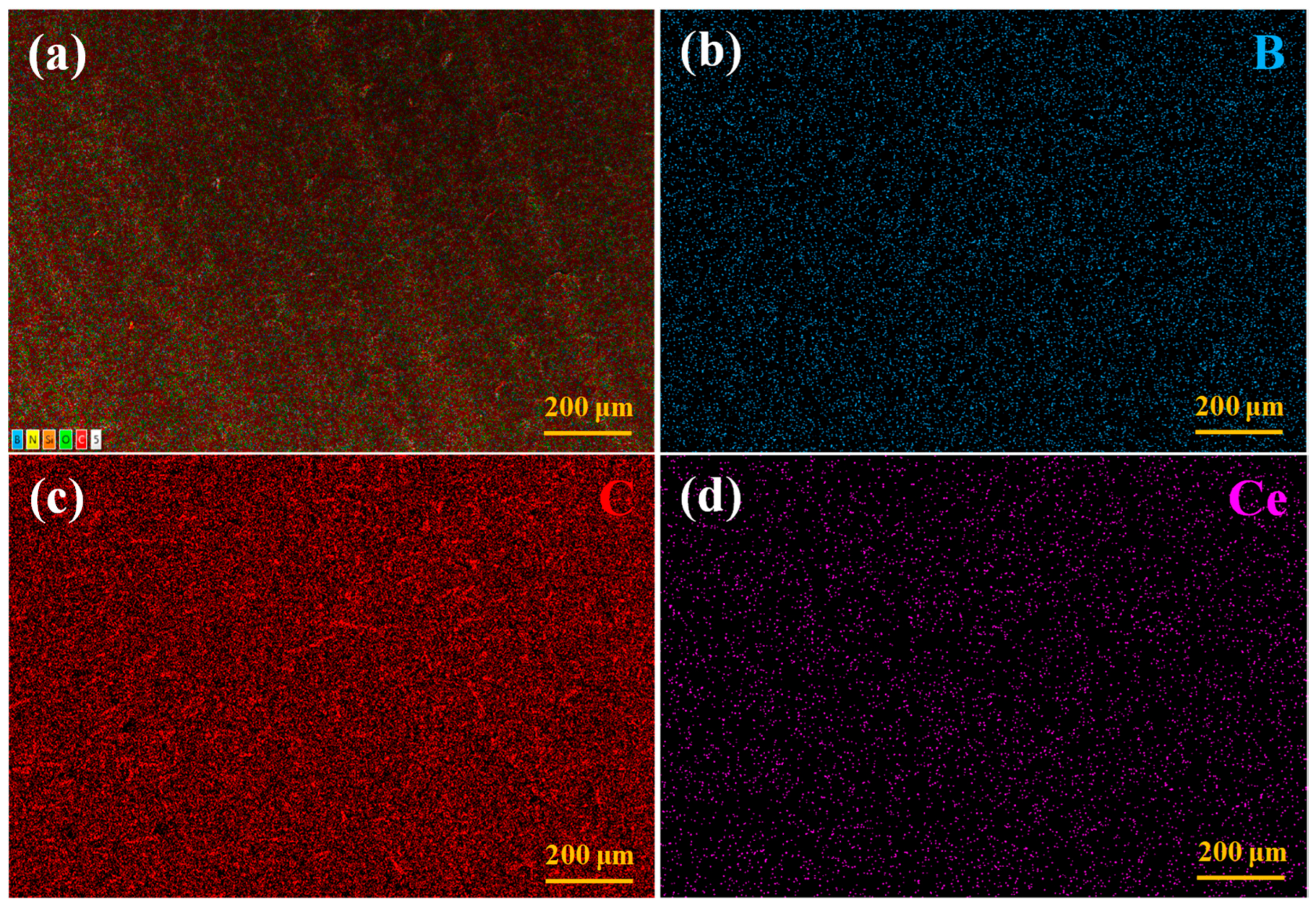
3.2. Microscopic Morphology of the Coatings

In order to observe the dispersion state of fillers such as Ce(NO3)3·6H2O within the coatings, the surface morphology and elemental species of the coatings with varying cerium nitrate contents were analysed by FE-SEM and EDS techniques, and the results are shown in Figure 3.
The surface morphology of Ce coatings with different Ce(NO3)3·6H2O contents is shown in Figure 3(a1–f1). A comparison of Figure 3(a1,b1–f1) with the reveals that the addition of Ce(NO3)3·6H2O does not significantly alter the surface morphology of the coatings. All Ce-doped coatings exhibit a similar surface appearance to that of the undoped OCF1.5–15 coating, with no observable Ce(NO3)3·6H2O particles on the surface. The elemental compositions of the coating surfaces were further analysed by EDS, as shown in Figure 3(a2–f2). According to Figure 3(a2), the OCF1.5–15 coating contains only the elements B, C, N, O, and a small amount of Si. From Figure 3(b2–f2), the surfaces of different Ce coatings contain Ce elements in addition to B, C, N, O, and Si elements, and the relative intensities of the corresponding peaks are gradually enhanced. This is due to the gradual increase in the Ce(NO3)3·6H2O content in the coatings.
For the Ce-coated group containing the Ce(NO3)3·6H2O corrosion inhibitor, all parameters except for the cerium nitrate content remained constant. Therefore, the Ce2.5 coating was chosen as a representative sample, and the distribution of fillers such as Ce(NO3)3·6H2O on its surface was analysed by EDS energy spectroscopy. The results are shown in Figure 4. Figure 4a illustrates the types of elements contained in the coating, which mainly contains Ce, O, N, B, and C. The B element is the signature element of the A-BNNS3 filler and its distribution within the coating is indicative of the distribution of the A-BNNS3 filler.
From Figure 4b, it can be seen that the B element is uniformly diffusely distributed inside the coating, and no obvious concentration phenomenon is found, indicating that the A-BNNS3 filler is uniformly distributed inside the coating, and no agglomeration phenomenon occurs. The characteristic element of oxidised carbon fibres is elemental C, and the presence of carbon fibres triggers a high density concentration of elemental C. Figure 4c demonstrates the distribution of elemental C in the coating, which is in two states: a concentrated distribution in the form of rods and a uniform diffuse distribution inside the coating. Among them, the concentrated distribution of rods is caused by the presence of OCF1.5, and the location of the concentration is the location of the distribution of OCF1.5. In addition, organic polymers, such as resins and curing agents, provide elemental C to the coating, which triggers a diffuse distribution of the C element.
Ce is a characteristic element of Ce(NO3)3·6H2O, and its distribution in the coating can reflect the distribution of Ce(NO3)3·6H2O. As shown in Figure 4d, the elemental Ce exhibits a uniform and diffuse distribution throughout the coating, without any regions with a high concentration. This observation confirms that cerium nitrate is homogeneously dispersed within the coating matrix. This uniform distribution is attributed to the dissolution of cerium nitrate in acetone during the coating preparation process.

3.3. TC of Ce Coatings

The TC of the coatings is closely related to their filler composition. The addition of Ce(NO3)3·6H2O alters the filler composition within the coating, which may influence its TC. Therefore, this section evaluates the TC of the Ce-doped coatings through TC measurements to elucidate the effect of the incorporation of Ce(NO3)3·6H2O. The test results of the TC of various Ce coatings are presented in Figure 5. As can be seen from the figure, the TC of the Ce coating did not change significantly with the elevation of the Ce(NO3)3·6H2O content. This is due to the fact that during the preparation of the coating, the solid granular Ce(NO3)3·6H2O is dissolved in acetone and is diffusely distributed inside the coating. Therefore, the addition of Ce(NO3)3·6H2O does not affect the distribution state of the filler inside the coating; furthermore, the TC is not greatly affected.

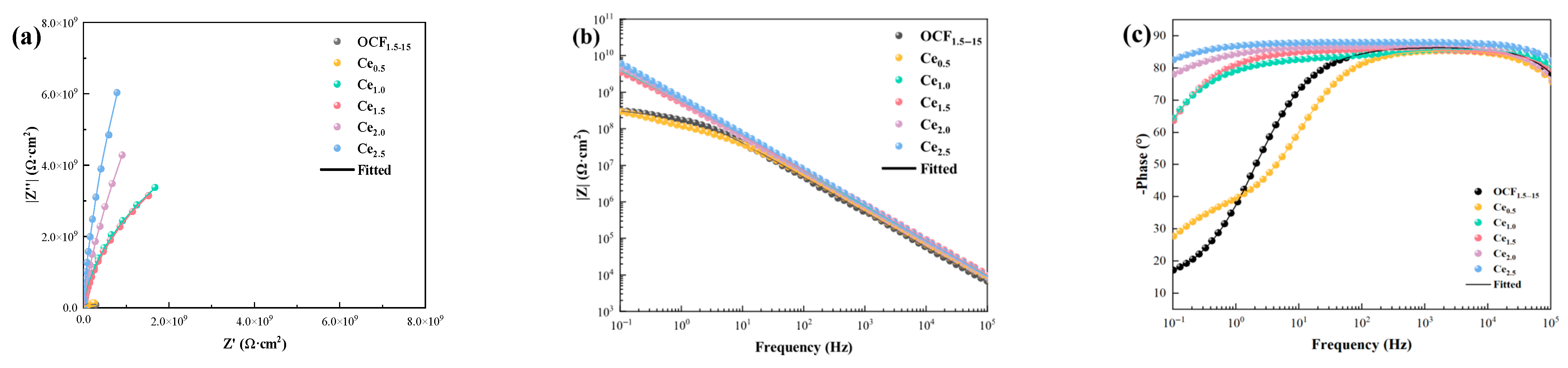
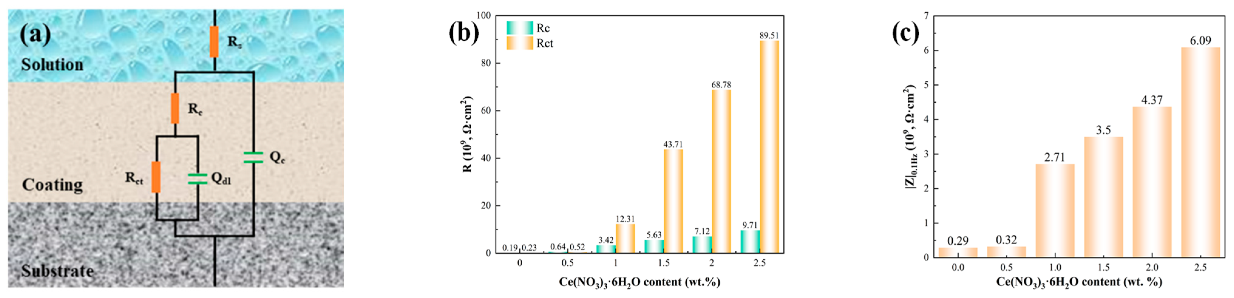
3.4. Corrosion-Resistant Properties of Coatings

In order to investigate the effect of the Ce(NO3)3·6H2O content on the corrosion resistance of Ce coatings, the coatings were tested using EIS after 4 weeks of immersion in 3.5 wt.% NaCl at 80 °C. The results are shown in Figure 6. In the Nyquist plot (shown in Figure 6a), the radius of the impedance arc increases with the increase in the Ce(NO3)3·6H2O content.
Figure 6a shows the Nyquist plots from the EIS test results for different coatings. As illustrated, the OCF1.5–15 coating, which contains no Ce(NO3)3·6H2O, exhibits the smallest impedance arc radius. With increasing Ce(NO3)3·6H2O content, the capacitive arc radius correspondingly increases. The Ce2.5 coating has the largest impedance arc radius. This indicates that the incorporation of Ce(NO3)3·6H2O enhances the corrosion resistance of the coating. And the corrosion resistance of the coating was enhanced with the increase in the Ce(NO3)3·6H2O content. In the Bode plot (see Figure 6b), after the coating has been immersed in a corrosive environment for 4 weeks, the |Z|0.1Hz of the OCF1.5–15 coating is only 3.05 × 10⁸ Ω·cm2 and has been characterised by an obvious second time constant, indicating poor corrosion protection. When Ce(NO3)3·6H2O was added to the Ce0.5 coating, although |Z|0.1Hz appeared to rise a little, it still appeared to have an obvious second time constant and a weak corrosion resistance. Thereafter, when the content of Ce(NO3)3·6H2O in the coatings exceeded 1.0 wt.%, the EIS results consistently exhibited a diagonal line with increasing content, without a pronounced second time constant. The phase angle test results are shown in Figure 6c. In the EIS testing of coatings, the magnitude of the phase angle at a frequency of 0.1 Hz can be used to indicate the strength of the coating’s corrosion resistance. The larger the phase angle, the stronger the corrosion resistance of the coating. Additionally, coatings with good corrosion resistance exhibit a stable phase angle plateau in the mid-frequency range. The wider the range corresponding to this plateau, the better the corrosion resistance of the coating. As shown in Figure 6c, the OCF1.5–15 coating has the weakest corrosion resistance. Subsequently, as the content of Ce(NO3)3·6H2O in the coating increases, the corrosion resistance of the coating gradually improves. This behaviour suggests that the coatings possess excellent anti-corrosion properties.
The EIS results were fitted using the equivalent circuit model depicted in Figure 7a through ZsimpWin V3.6 software. In the equivalent circuit model, Rs, Rc, Rct, Qc, and Qdl, respectively, represent the solution resistance, coating resistance, charge transfer resistance, coating capacitance, and double-layer capacitance. Under normal circumstances, Rc is used to evaluate the barrier performance of the coating, and Rct is positively correlated with the anti-corrosion property of the coating. Therefore, Rc and Rct can be used to evaluate the anti-corrosion performance of the coating to a certain extent. The fitting results, presented in Figure 7b, demonstrate that the corrosion resistance of the coating gradually improves with increasing cerium nitrate content. When the coating contains 2.5 wt.% cerium nitrate, the anti-corrosion property of the coating is the strongest.
The value of |Z|0.1Hz is commonly used as a semi-quantitative indicator to evaluate the anti-corrosion performance of coatings [21,22]. A higher |Z|0.1Hz value corresponds to better corrosion resistance. The |Z|0.1Hz results for Ce coatings with varying cerium nitrate contents are shown in Figure 7c. As can be seen from the figure, with the increase in cerium nitrate content, the corrosion resistance of the coatings improves progressively. When the coating contains 2.5 wt.% cerium nitrate, the anti-corrosion property of the coating is the strongest. The anti-corrosion property of the Ce2.5 coating is 20 times higher than that of the OCF1.5–15 coating.

3.5. Self-Healing Properties of Coatings

To investigate the influence of the Ce(NO3)3·6H2O content on the self-repairing performance of Ce coatings and the mechanism of its action, a craft knife with a blade width of 0.3 mm was used to make “cross” marks on the surface of the coatings to create artificial damage. The damaged coating was then immersed in a 3.5 wt.% NaCl solution corrosion environment (hereinafter referred to as the corrosion environment) at 80 °C for one week.
After exposure, the macroscopic surface morphology of the coatings and the microscopic features at the scratch sites were examined. Additionally, XPS was employed to analyse the composition of the products formed on the substrate surface.

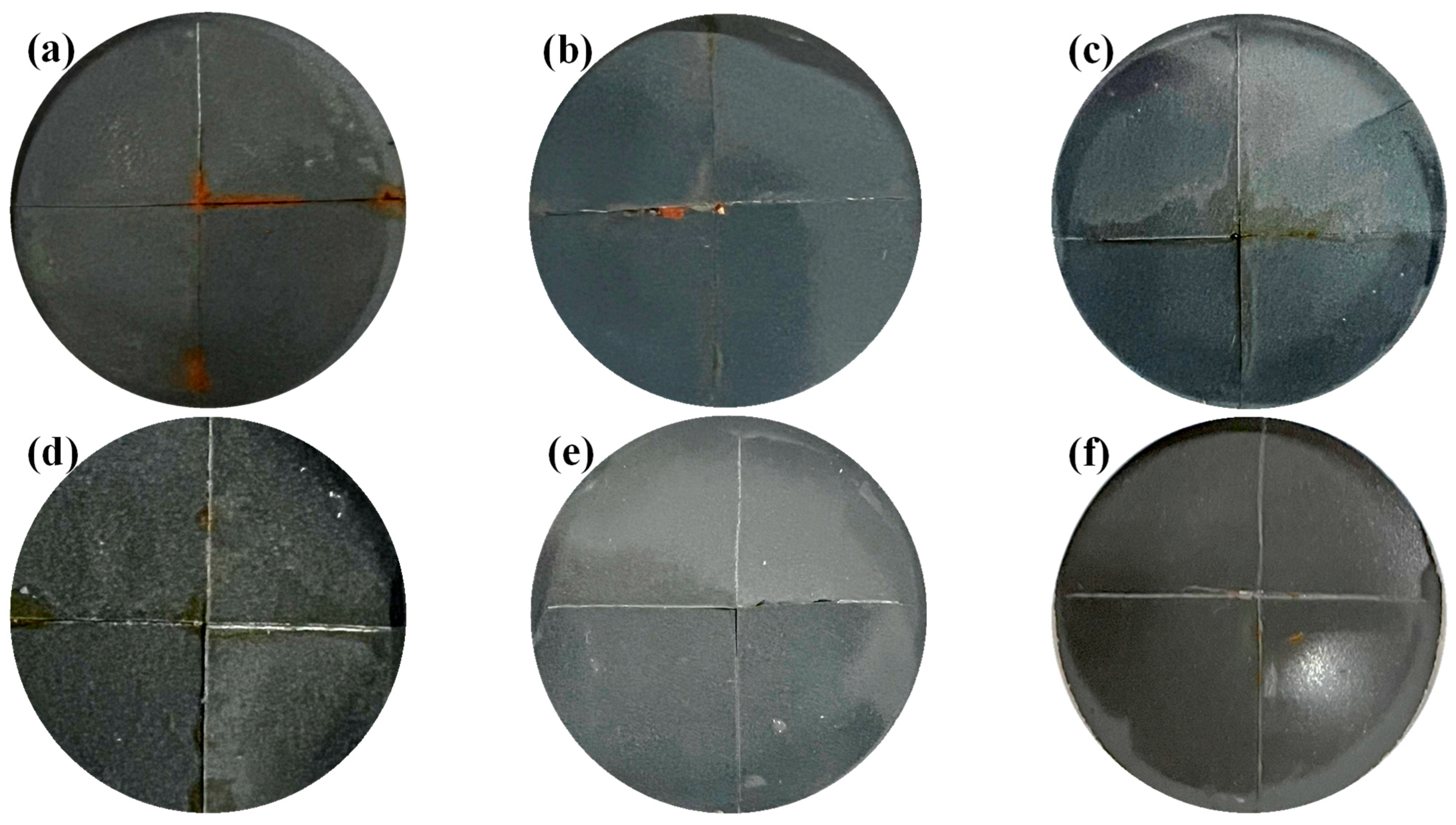
3.5.1. Macroscopic Morphology of Coating Damage

The macroscopic morphology of broken Ce coatings with different Ce(NO3)3·6H2O contents is presented in Figure 8. The OCF1.5–15 coating without Ce(NO3)3·6H2O exhibited extensive yellow rust on its surface after one week of immersion in the corrosive environment, and the rust was most obvious at the breakage area (seen in Figure 8a). This observation indicates that significant corrosion occurred in the metal substrate at the site of the coating failure. When the coating contains only 0.5 wt.% of Ce(NO3)3·6H2O (see Figure 8b), there are still some yellow rust marks on the surface of the Ce0.5 coating. However, in comparison to the OCF1.5–15 coating, the number of yellow rust marks was significantly reduced and limited to the broken areas only. This suggests that the incorporation of Ce(NO3)3·6H2O imparts a degree of self-healing capability to the coating, although the self-repairing performance at this concentration remains substantially limited.
With a further increase in the Ce(NO3)3·6H2O content to 1.0 wt.% and 1.5 wt.% (see Figure 8c,d), the presence of yellow rust marks on the coating surface was further diminished. Only minor yellowish deposits were observed in the damaged areas, with no evident accumulation of rust.
When the Ce(NO3)3·6H2O content in the coating exceeded 2.0 wt.% (see Figure 8e,f), the coating surface appeared smooth and uniform, with no visible yellow rust marks, and the broken area showed a bright metallic substrate colour. This shows that when the cerium nitrate content in the coating exceeds 2.0 wt.%, the coating exhibits excellent self-healing capabilities and provides effective protection of the metal substrate at the damaged site. In summary, the doping of Ce(NO3)3·6H2O imparts self-healing functionality to the Ce coating. Moreover, the self-healing properties of the coatings improve progressively with increasing Ce(NO3)3·6H2O content. Under corrosive conditions, the minimum addition of Ce(NO3)3·6H2O was 2.0 wt.% in order to provide the Ce coating with good self-healing properties.

3.5.2. Microscopic Morphology of the Base Metal at the Damage Site

We employed a utility knife featuring a blade width of precisely 0.3 mm to carefully scrape away the coating in the vicinity of the scratch, thereby exposing the metal substrate. The microscopic morphology of the metal substrate at the scratched regions for different Ce coating samples was observed by FE-SEM, and the corresponding results are presented in Figure 9. As can be seen in Figure 9a, in the absence of the cerium nitrate corrosion inhibitor, the OCF1.5–15 coating exhibited severe corrosion at the scratched area, accompanied by a substantial accumulation of corrosion products.
When 0.5 wt.% cerium nitrate was added to the coating, the Ce0.5 coating possessed some self-repairing properties. The build-up of corrosion products on the surface of the metal substrate within the scratches was reduced, and the degree of corrosion was weakened (see Figure 9b). With an increased cerium nitrate content of 1.0 wt.%, the accumulation of corrosion products on the surface of the metal substrate within the scratches continued to decrease, suggesting an enhanced inhibition of substrate corrosion, as illustrated in Figure 9c. With increasing cerium nitrate content, the self-healing performance of the Ce coating was progressively enhanced. When the cerium nitrate content in the coating reaches 2.5 wt.%, the surface of the metal substrate in the scratch is neat and smooth, and there is almost no obvious accumulation of corrosion products. This indicates that corrosion was effectively suppressed (see Figure 9f), demonstrating that the coating exhibits excellent self-healing capabilities at this concentration.
In summary, the incorporation of cerium nitrate into the coating imparts self-healing properties, which become more pronounced with increasing cerium nitrate content. Upon mechanical damage to the coating surface, the self-healing functionality enables the cerium nitrate-containing coating to effectively mitigate corrosion at the exposed metal substrate, thereby enhancing the protective performance of the coating.

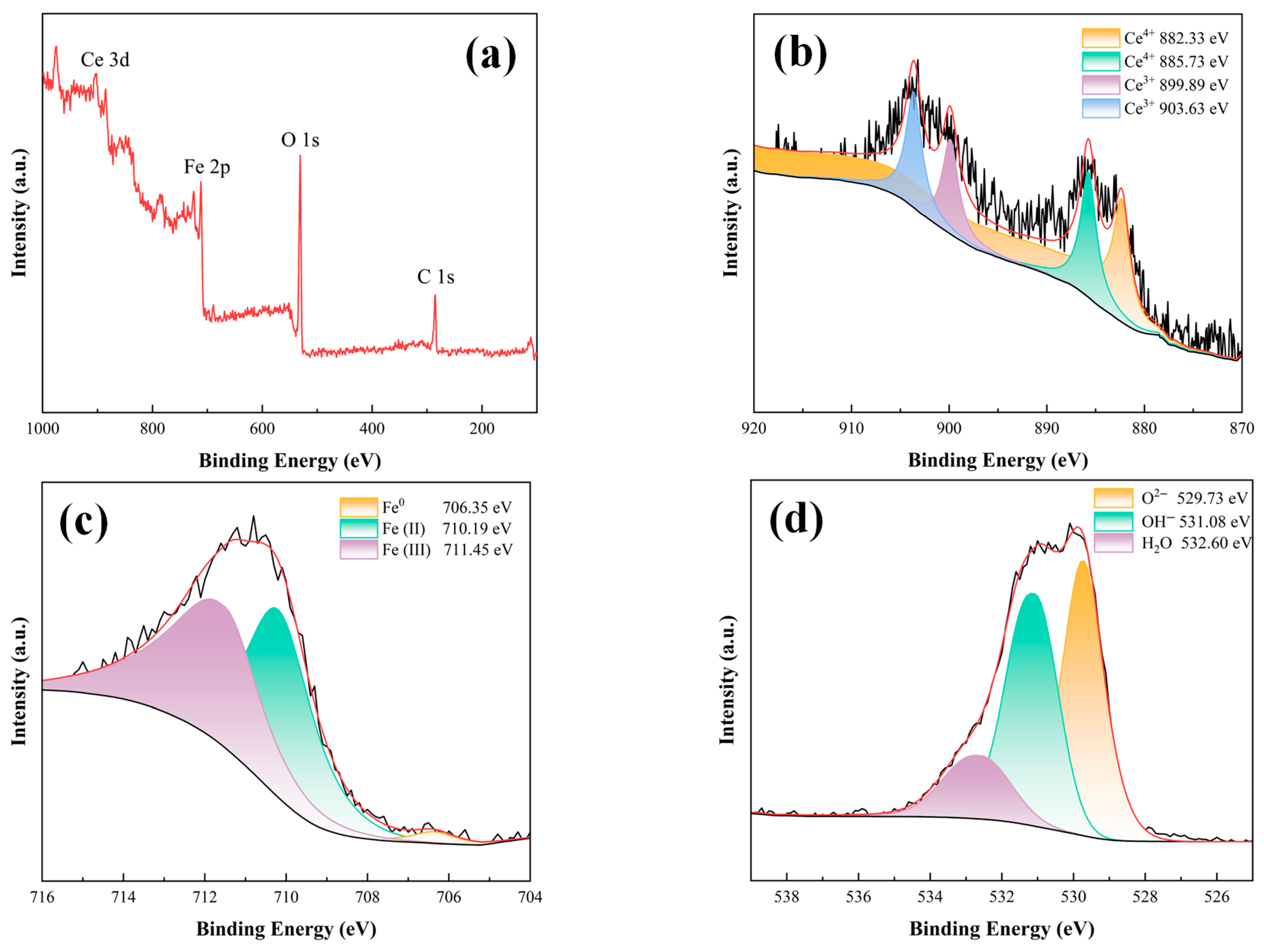
3.5.3. Compositional Analyses of Substrate Metal Surface Products at Breaks

In summary, doping Ce(NO3)3·6H2O into OCF1.5–15 coatings can give the coatings certain self-healing properties. For the doped cerium nitrate, the self-healing performance of the coatings was gradually enhanced with the increase in Ce(NO3)3·6H2O content. The coating with the strongest self-healing property is the Ce2.5 coating with 2.5 wt.% Ce(NO3)3·6H2O. Based on the test results for the anticorrosive and self-repairing properties of Ce coating groups, it was confirmed that the addition of cerium nitrate significantly enhances both properties. Since all aspects of Ce-containing coatings are the same except for the Ce(NO3)3·6H2O content, the Ce2.5 coating was selected as a representative coating.
The composition of the metal surface products at the break was analysed by XPS technology to elucidate the role of Ce ions in influencing the corrosion resistance and self-repair performance of the coating, and the results are shown in Figure 10. According to Figure 10a, the metal surface at the coating breakage place mainly contains Ce, Fe, O, and C elements. Among them, the C element is an element in the metal material, which hardly reacts in the corrosive environment, so it is not considered in the result analysis. The Ce 3d high-resolution XPS spectra (Figure 10b) reveal four prominent fitted peaks at binding energies of 882.33 eV, 885.73 eV, 899.89 eV, and 903.63 eV, which are attributed to Ce4+ 3d5/2 and Ce3+ 3d3/2, respectively [23,24,25,26,27]. The Fe 2p high-resolution spectra (see Figure 10c) show the presence of three major fitted peaks at 706.35 eV, 710.19 eV, and 711.45 eV, corresponding to atomic iron (Fe0), FeO, and FeOOH, respectively [28,29,30]. The test results of the O 1s high-resolution spectra are shown in Figure 10d, with three major fitted peaks at 529.73 eV, 531.08 eV, and 532.60 eV, assigned to O2−, OH, and H2O, respectively [31,32,33].

4. The Influence of Ce(NO3)3·6H2O Content on Coating Properties

The results of the above studies show that doping cerium nitrate into OCF1.5–15 coatings results in a greater enhancement of the corrosion resistance and self-repairing capabilities of the coatings. When the coating containing Ce3+ is exposed to a corrosive environment, aggressive species such as water, OH, and O2 infiltrate the coating. At this time, Ce3+ inside the coating will react with the OH and O2 penetrating the coating to obtain Ce(OH)3, which can further undergo a dehydration reaction to yield Ce2O3, as illustrated in Equations (1)–(3) [34]. In addition, Ce3+ can be oxidised to Ce4+ in oxygen-containing corrosive environments, and CeO2 can be obtained by combining with OH and dehydrating; see Equations (4)–(6) [35].
O 2 + 2 H 2 O + 4 e 4 O H
C e 3 + + 3 O H C e ( O H ) 3
2 C e ( O H ) 3 C e 2 O 3 + 3 H 2 O
C e 3 + + 4 O H + O 2 C e ( O H ) 2 2 +
C e ( O H ) 2 2 + + 2 O H 4 C e ( O H ) 4
C e ( O H ) 4 C e O 2 + 2 H 2 O
It is worth noting that the service time of the coating in the corrosive environment is relatively short. The corrosion medium penetrated part of the coating but did not reach the carbon steel substrate. Under these conditions, the above reaction occurs in the coating, and Ce2O3 and CeO2 can be formed as a filler inside the coating and block the penetration of corrosive media channels, thus enhancing the corrosion resistance of the coating. As the corrosion time increases, a small amount of the corrosive medium eventually reaches the carbon steel substrate. At this stage, the bottom layer of the coating, which is in direct contact with the metal, becomes exposed to the corrosive environment. The site of the above reaction increases the surface location of carbon steel, and the Ce2O3 and CeO2 generated on the surface of the carbon steel are used as a passivation film to cover its surface, further slowing down its corrosion process.
Furthermore, the incorporation of cerium nitrate endows the OCF1.5–15 coating with a certain degree of self-repairing capability. When the coating surface damage occurs, there are many corrosive media that do not need to penetrate through the coating directly to the surface of the carbon steel at the point of damage. Therefore, the main place where the above reaction occurs is the metal surface where the coating is damaged. In this case, Ce3+ is supplied from the coating material surrounding the damaged area. The Ce2O3 generated by the reaction directly covers the surface of the carbon steel at the breakage point to form a passivation film, which inhibits the corrosion of the carbon steel metal. The content of cerium nitrate plays a crucial role in determining the corrosion protection and self-repairing effectiveness of the coating; as the concentration of cerium nitrate increases, both the anti-corrosion performance and self-healing ability of the coating are significantly improved.
However, since cerium nitrate was completely dissolved in the acetone diluent during the coating preparation process; it became uniformly dispersed throughout the coating and did not alter the distribution of other fillers. Consequently, the addition of cerium nitrate has only a minimal effect on the TC of the coating.

5. Conclusions

The results of this study demonstrate that incorporating the cerium nitrate inorganic corrosion inhibitor into the OCF1.5–15 water jacket furnace coating has an effect on the overall performance of the coating. The following conclusions can be drawn:
  • The incorporation of cerium nitrate into the OCF1.5–15 coating has no significant impact on its TC. When the coating is doped with cerium nitrate, both the corrosion resistance and self-repairing performance of the coating are enhanced with the increase in cerium nitrate content;
  • The Ce2.5 coating offers outstanding performance in terms of its TC, corrosion resistance, corrosion inhibitor-assisted healing capability, and long-term reliability. The TC is about 1.4 W/(m·K). Additionally, it shows outstanding corrosion resistance, with the impedance modulus at |Z|0.1 Hz reaching 6.08 × 10⁹ Ω·cm2 after 4 weeks of immersion in 3.5 wt.% NaCl solution at 80 °C—representing a 32% improvement compared to the OCF1.5–15 coating;
  • The form in which the inorganic corrosion inhibitor exists within the coating plays a critical role in determining the coating’s performance. As cerium nitrate is dissolved in acetone during the preparation process, Ce3+ ions are uniformly dispersed throughout the coating. Consequently, the doping of cerium nitrate does not trigger changes in the distribution of fillers within the coating and does not produce holes with an extension of the service time. From this, it can be concluded that while the doping of cerium nitrate does not significantly affect the TC of the coating, it effectively enhances the coating’s corrosion resistance. When the coating is completely saturated by the electrolyte, Ce3+ will be dissolved in water, forming a protective passivation film on the surface of the carbon steel substrate to inhibit the corrosion of carbon steel.

Author Contributions

Conceptualization, Y.Y. and J.W.; Data curation, M.L. and D.F.; Formal analysis, Q.M.; Methodology, J.Z. (Jing Zhou); Project administration, Y.L. and Z.X.; Writing, J.L., X.J., J.T., J.Z. (Jianfeng Zhang) and X.S. All authors have read and agreed to the published version of the manuscript.

Funding

This research received no external funding.

Institutional Review Board Statement

Not applicable.

Informed Consent Statement

Not applicable.

Data Availability Statement

The original contributions presented in this study are included in the article. Further inquiries can be directed to the corresponding authors.

Conflicts of Interest

The authors declare no conflicts of interest.

References

  1. Zou, C.; Zhao, Q.; Zhang, G.; Xiong, B. Energy revolution: From a fossil energy era to a new energy era. Nat. Gas Ind. B 2016, 3, 1–11. [Google Scholar] [CrossRef]
  2. Qu, C.; Zhou, X.; Wei, L. Thermal characteristics study on the gathering and transportation process of crude oil by mixing with hot water. Case Stud. Therm. Eng. 2025, 69, 106065. [Google Scholar] [CrossRef]
  3. Lopez, D.A.; Perez, T.; Simison, S.N. The influence of microstructure and chemical composition of carbon and low alloy steels in CO2 corrosion. A state-of-the-art appraisal. Mater. Des. 2003, 24, 561–575. [Google Scholar] [CrossRef]
  4. Solovyeva, V.A.; Almuhammadi, K.H.; Badeghaish, W.O. Current downhole corrosion control solutions and trends in the oil and gas industry: A review. Materials 2023, 16, 1795. [Google Scholar] [CrossRef]
  5. Lu, R.; Xu, F.; Cui, Y.; Bao, D.; Yuan, S.; Sun, Y.; Pei, L.; Jiang, Y.; Zhu, J.; Wang, H. Novel thermal conductivity and anti-corrosion coating with hydrophobic properties for heat exchanger applications. Prog. Org. Coat. 2024, 186, 108004. [Google Scholar] [CrossRef]
  6. Xu, F.; Zhang, M.; Cui, Y.; Bao, D.; Peng, J.; Gao, Y.; Lin, D.; Geng, H.; Zhu, Y.; Wang, H. A novel polymer composite coating with high thermal conductivity and unique anti-corrosion performance. Chem. Eng. J. 2022, 439, 135660. [Google Scholar] [CrossRef]
  7. Ma, H.; Gao, B.; Wang, M.; Yuan, Z.; Shen, J.; Zhao, J.; Feng, Y. Strategies for enhancing thermal conductivity of polymer-based thermal interface materials: A review. J. Mater. Sci. 2021, 56, 1064–1086. [Google Scholar] [CrossRef]
  8. Yan, Y.; Jiang, X.; Liao, K.; Leng, J.; Qin, M.; Lyu, X.; He, G.; Zhao, S.; He, T.; Zheng, D. Effects of OCF content and oxidation treatment on thermal conductivity and corrosion resistance of CF/BN/EPN coating. Surf. Coat. Technol. 2024, 481, 130664. [Google Scholar] [CrossRef]
  9. Pan, D.; Zhang, X.; Yang, G.; Shang, Y.; Su, F.; Hu, Q.; Patil, R.R.; Liu, H.; Liu, C.; Guo, Z. Thermally conductive anticorrosive epoxy nanocomposites with tannic acid-modified boron nitride nanosheets. Ind. Eng. Chem. Res. 2020, 59, 20371–20381. [Google Scholar] [CrossRef]
  10. Fenker, M.; Balzer, M.; Kappl, H. Corrosion protection with hard coatings on steel: Past approaches and current research efforts. Surf. Coat. Technol. 2014, 257, 182–205. [Google Scholar] [CrossRef]
  11. Vijayan, P.P.; Al-Maadeed, M. Self-repairing composites for corrosion protection: A review on recent strategies and evaluation methods. Materials 2019, 12, 2754. [Google Scholar] [CrossRef] [PubMed]
  12. Al-Amiery, A.A.; Isahak, W.N.R.W.; Al-Azzawi, W.K. Corrosion inhibitors: Natural and synthetic organic inhibitors. Lubricants 2023, 11, 174. [Google Scholar] [CrossRef]
  13. Ahmed, M.A.; Amin, S.; Mohamed, A.A. Current and emerging trends of inorganic, organic and eco-friendly corrosion inhibitors. RSC Adv. 2024, 14, 31877–31920. [Google Scholar] [CrossRef] [PubMed]
  14. Chauhan, D.S.; Verma, C.; Quraishi, M.A. Molecular structural aspects of organic corrosion inhibitors: Experimental and computational insights. J. Mol. Struct. 2021, 1227, 129374. [Google Scholar] [CrossRef]
  15. Verma, C.; Ebenso, E.E.; Quraishi, M.A.; Hussain, M.C. Recent developments in sustainable corrosion inhibitors: Design, performance and industrial scale applications. Mater. Adv. 2021, 2, 3806–3850. [Google Scholar] [CrossRef]
  16. Moghaddam, P.N.; Amini, R.; Kardar, P.; Ramezanzadeh, B. Epoxy-ester coating reinforced with cerium (III)-tannic acid-based hybrid pigment for effective mild-steel substrate corrosion protection. Prog. Org. Coat. 2021, 161, 106485. [Google Scholar] [CrossRef]
  17. Danaee, I.; Darmiani, E.; Rashed, G.R.; Zaarei, D. Self-healing and anticorrosive properties of Ce (III)/Ce (IV) in nanoclay–epoxy coatings. Iran. Polym. J. 2014, 23, 891–898. [Google Scholar] [CrossRef]
  18. Habib, S.; Nawaz, M.; Kahraman, R.; Ahmed, E.M.; Shakoor, R. Effect of the modified hybrid particle on the corrosion inhibition performance of polyolefin based coatings for carbon steel. J. Sci. Adv. Mater. Devices 2022, 7, 100466. [Google Scholar] [CrossRef]
  19. Ren, C.; Huang, Y.; Hao, W.; Zhang, D.; Luo, X.; Ma, L.; Wang, J.; Chowwanonthapunya, T.; Dong, C.; Li, X. Multi-action self-healing coatings with simultaneous recovery of corrosion resistance and adhesion strength. J. Mater. Sci. Technol. 2022, 101, 18–27. [Google Scholar] [CrossRef]
  20. Yan, Y.; Liao, K.; Hu, J.; Qin, M.; He, T.; Ou, T.; Fan, Y.; Leng, J.; He, G. Effects of h-BN content and silane functionalization on thermal conductivity and corrosion resistance of h-BN/EPN coating. Surf. Coat. Technol. 2024, 476, 130185. [Google Scholar] [CrossRef]
  21. Jiang, X.; Qin, M.; Yan, Y.; Li, Y.; Xie, Z.; He, G.; Jiang, P.; Wu, H.; Liao, K. Effects of Na2MoO4 Content on the Properties of CF/BN/EPN Heat Exchangers Coatings. Mater. Chem. Phys. 2025, 345, 131127. [Google Scholar] [CrossRef]
  22. Wang, H.; He, Y.; Fei, G.; Wang, C.; Shen, Y.; Zhu, K.; Sun, L.; Rang, N.; Guo, D.; Wallace, G.G. Functionalizing graphene with titanate coupling agents as reinforcement for one-component waterborne poly (urethane-acrylate) anticorrosion coatings. Chem. Eng. J. 2019, 359, 331–343. [Google Scholar] [CrossRef]
  23. Yan, Z.; Kang, Y.; Li, D.; Liu, Y.C. Catalytic oxidation of sulfur dioxide over α-Fe2O3/SiO2 catalyst promoted with Co and Ce oxides. Korean J. Chem. Eng. 2020, 37, 623–632. [Google Scholar] [CrossRef]
  24. Gandamalla, A.; Manchala, S.; Verma, A.; Fu, Y.-P.; Shanker, V. Development of highly efficient Ce(MoO4)2/g-C3N4 composite for the photocatalytic degradation of methylene blue and ciprofloxacin under visible light. J. Mol. Struct. 2024, 1297, 136896. [Google Scholar] [CrossRef]
  25. Arul, N.S.; Mangalaraj, D.; Ramachandran, R.; Grace, A.N.; Han, J.I. Fabrication of CeO2/Fe2O3 composite nanospindles for enhanced visible light driven photocatalysts and supercapacitor electrodes. J. Mater. Chem. A 2015, 3, 15248–15258. [Google Scholar] [CrossRef]
  26. Latha, P.; Prakash, K.; Karuthapandian, S. Facile fabrication of visible light-driven CeO2/PMMA thin film photocatalyst for degradation of CR and MO dyes. Res. Chem. Intermed. 2018, 44, 5223–5240. [Google Scholar] [CrossRef]
  27. Purbia, R.; Choi, S.Y.; Kim, H.J.; Ye, B.; Jeong, B.; Lee, D.H.; Park, H.; Kim, H.-D.; Baik, J.M. Cu-and Ce-promoted nano-heterostructures on vanadate catalysts for low-temperature NH3–SCR activity with improved SO2 and water resistance. Chem. Eng. J. 2022, 437, 135427. [Google Scholar] [CrossRef]
  28. Liu, Q.; Wang, J.; Chong, Y.; Liu, J. Inhibition effect of green Betaine type surfactants on Q235 steel in 1 mol·L−1 hydrochloric acid: The experimental and theoretical research. J. Mol. Struct. 2022, 1262, 133023. [Google Scholar] [CrossRef]
  29. Zeng, Q.; Huang, Y.; Wang, H.; Huang, L.; Hu, L.; Zhong, H.; He, Z. A novel composite of almandine supported humboldtine nanospheres, in situ synthesized from natural almandine, possesses high removal efficiency of Cr (VI) over a wide pH range. J. Hazard. Mater. 2020, 383, 121199. [Google Scholar] [CrossRef]
  30. Chen, L.; Liu, W.; Dong, B.; Zhao, Y.; Zhang, T.; Fan, Y.; Yang, W. Insight into electrochemical passivation behavior and surface chemistry of 2205 duplex stainless steel: Effect of tensile elastic stress. Corros. Sci. 2021, 193, 109903. [Google Scholar] [CrossRef]
  31. Sarantuya, L.; Sevjidsuren, G.; Altantsog, P.; Tsogbadrakh, N. Synthesis, structure and electronic properties of Li4Ti5O12 anode material for lithium ion batteries. Solid State Phenom. 2018, 271, 9–17. [Google Scholar] [CrossRef]
  32. Shi, Y.; Li, J.; Sun, Y.; Wan, D.; Wan, H.; Wang, Y. FeOOH coupling and nitrogen vacancies functionalized g-C3N4 heterojunction for efficient degradation of antibiotics: Performance evaluation, active species evolution and mechanism insight. J. Alloys Compd. 2022, 903, 163898. [Google Scholar] [CrossRef]
  33. Jalil, P.A.; Faiz, M.; Tabet, N.; Hamdan, N.; Hussain, Z. A study of the stability of tungstophosphoric acid, H3PW12O40, using synchrotron XPS, XANES, hexane cracking, XRD, and IR spectroscopy. J. Catal. 2003, 217, 292–297. [Google Scholar] [CrossRef]
  34. Dastgheib, A.; Zarebidaki, A.; Attar, M.M. Enhanced barrier properties of epoxy coating containing CaCO3 microparticles modified with cerium nitrate. Prog. Org. Coat. 2020, 144, 105660. [Google Scholar] [CrossRef]
  35. Dastgheib, A.; Mohammadzadeh Attar, M.; Zarebidaki, A. Evaluation of corrosion inhibition of mild steel in 3.5 wt% NaCl solution by cerium nitrate. Met. Mater. Int. 2020, 26, 1634–1642. [Google Scholar] [CrossRef]
Figure 1. XRD pattern of Ce(NO3)3·6H2O.
Coatings 15 00818 g001
Figure 2. (a) SEM morphology and (b) EDS elemental test results of Ce(NO3)3·6H2O.
Coatings 15 00818 g002
Figure 3. Cross-sectional SEM images of coatings: (a1) OCF1.5–15 (b1) Ce0.5, (c1) Ce1.0, (d1) Ce1.5, (e1) Ce2.0, and (f1) Ce2.5; Surface SEM-EDS results of coatings: (a2) OCF1.5–15, (b2) Ce0.5, (c2) Ce1.0, (d2) Ce1.5, (e2) Ce2.0, and (f2) Ce2.5.
Coatings 15 00818 g003aCoatings 15 00818 g003b
Figure 4. EDS mapping of Ce2.5 coating. (a) is overall situation; (b) is B; (c) is C; (d) is Ce.
Coatings 15 00818 g004
Figure 5. TC test results for different Ce coatings.
Coatings 15 00818 g005
Figure 6. EIS test results for Ce coatings. (a) is Nyquist; (b) is Bode-|Z|; (c) is Bode-phase.
Coatings 15 00818 g006
Figure 7. (a) Equivalent circuit models: R(Q(R(QR))); (b) The fitted parameters of Rc and Rct for OCF1.5–15 coating and Ce coatings; (c) The variation in |Z|0.1Hz of different coatings after soaking in 3.5 wt.% sodium chloride for 4 weeks at 80 °C.
Coatings 15 00818 g007
Figure 8. The macroscopic morphology of different Ce coating breakages: (a) OCF1.5–15, (b) Ce0.5, (c) Ce1.0, (d) Ce1.5, (e) Ce2.0, and (f) Ce2.5.
Coatings 15 00818 g008
Figure 9. Micro-morphology of the metal substrate at the break of CF/BN/EPN self-healing coatings with different contents of cerium nitrate: (a) OCF1.5–15, (b) Ce0.5, (c) Ce1.0, (d) Ce1.5, (e) Ce2.0, and (f) Ce2.5.
Coatings 15 00818 g009
Figure 10. XPS deconvolution of the carbon steel surface where the Ce2.5 coating was broken: (a) XPS survey, (b) Ce 3d, (c) Fe 2p, and (d) O 1s.
Coatings 15 00818 g010
Table 1. Information on laboratory materials and reagents.
[No.]TitleSpecificationModelManufacturer
1Ce(NO3)3·6H2OAR99.99%Shanghai McLean Biochemical Technology Co., Shanghai, China
2CFcommodity-gradeφ5 × 20 μmShanghai Mitsuda Nano New Material Co., Shanghai, China
3h-BNNscommodity-grade100 nmShanghai Mitsuda Nano New Material Co., Shanghai, China
4EPNcommodity-gradeNPPN-630 LSouth Asia Plastic Industry Co., Taiwan, China
5curing agentcommodity-gradeAncamine 2280Shanghai Evonik Speciality Chemicals Co., Shanghai, China
6APTESAR99%Shanghai McLean Biochemical Technology Co., Shanghai, China
7ethanolAR99.9%Shanghai McLean Biochemical Technology Co., Shanghai, China
8ammoniaAR99.9%Shanghai McLean Biochemical Technology Co., Shanghai, China
9acetoneAR99.9%Shanghai McLean Biochemical Technology Co., Shanghai, China
10oxalateAR99.9%Shanghai McLean Biochemical Technology Co., Shanghai, China
11ammonium nitrateAR99.9%Shanghai McLean Biochemical Technology Co., Shanghai, China
Disclaimer/Publisher’s Note: The statements, opinions and data contained in all publications are solely those of the individual author(s) and contributor(s) and not of MDPI and/or the editor(s). MDPI and/or the editor(s) disclaim responsibility for any injury to people or property resulting from any ideas, methods, instructions or products referred to in the content.

