Article

An Analysis of the Tribological and Thermal Performance of PVDF Gears in Correlation with Wear Mechanisms and Failure Modes Under Different Load Conditions

1
Department of Mechanical Design, Faculty of Mechanical Engineering, University of Sarajevo, 71000 Sarajevo, Bosnia and Herzegovina
2
Institute of Machine Design, Faculty of Mechanical Engineering, Poznań University of Technology, 60-965 Poznań, Poland
3
Institute of Energy and Mechanical Engineering Named After A. Burkitbayev, Kazakh National Research Technical University, Satbayev Str., 22, Almaty 050013, Kazakhstan
4
Department of Woodworking and Fundamentals of Machine Design, Faculty of Forestry and Wood Technology, Poznań University of Life Sciences, 60-637 Poznań, Poland
5
Institute of Safety and Quality Engineering, Faculty of Engineering Management, Poznań University of Technology, 60-965 Poznań, Poland
*
Authors to whom correspondence should be addressed.
Coatings 2025, 15(7), 800; https://doi.org/10.3390/coatings15070800
Submission received: 19 May 2025 / Revised: 29 May 2025 / Accepted: 5 June 2025 / Published: 9 July 2025

Abstract

With engineering plastics increasingly replacing traditional materials in various drive and control gear systems across numerous industrial sectors, material selection for any gearwheel critically impacts its mechanical and thermal properties. This paper investigates the engagement of steel and Polyvinylidene Fluoride (PVDF) gear pairs tested under several load conditions to determine polymer gears’ characteristic service life and failure modes. Furthermore, recognizing that the application of polymer gears is limited by insufficient data on their temperature-dependent mechanical properties, this study establishes a correlation between the tribological contact, meshing temperatures, and wear coefficients of PVDF gears. The results demonstrate that the flank surface wear of the PVDF gears is directly proportional to the temperature and load level of the tested gears. Several distinct load-induced failure modes have been detected and categorized into three groups: abrasive wear resulting from the hardness disparity between the engaging surfaces, thermal failure caused by heat accumulation at higher load levels, and tooth fracture occurring due to stiffness changes induced by the compromised tooth cross-section after numerous operating cycles at a specific wear rate.

1. Introduction

With polymer gears increasingly used in demanding applications ranging from the automotive industry to medical equipment, robotics, and industrial machinery, it is vital to understand the parameters that influence their performance. This is a nontrivial undertaking, considering macromolecular materials and gear analysis’s intricate nature across diverse geometries and operational scenarios. The implementation of engineering plastics for industrial requirements is demanded by the need for lightweight components and the progressive development of polymer materials [1]. Consequently, the replacement of steel with plastic gears is encouraged by the beneficial lightweight properties of polymer materials, so today, almost every state-of-the-art drivetrain system, from low to advanced moderate operational loads, has successfully implemented polymer gears as essential elements of power and motion [2]. Several other factors also played a crucial role in the adaptation to contemporary industrial needs, where steel gear replacement was conditioned by many other advantages, such as dry running and self-lubrication capabilities, better noise and vibration properties, ease of fabrication, freedom in design and the applicability of new design solutions, and lower individual unit cost, which is especially significant in the batch and high-volume production of polymer gears [3,4].
Although polymer gears exhibit inferior mechanical properties and weaker thermal conductivity, limiting their use in specific domains, engineering practices are currently directed toward using and developing polymer composite materials reinforced with specific fibers to adjust and positively influence the corresponding base material [5]. In addition to conventional reinforcements of base material utilized by carbon and glass fibers that improve mechanical properties, such as Young’s modulus and tensile strength, friction-reducing fillers such as polytetrafluoroethylene (PTFE) can be applied to reduce the friction coefficient along with corresponding heat development in the contact area, therefore improving the efficiency and service life of the gear system [6,7,8]. With industrial preferences shifting to sustainable development, environmental factors are crucial in polymer gears’ contemporary design and development [9,10]. The environmental impact implies the minimization of use and the replacement of fossil-based polymer materials with bio-based and biodegradable polymers, i.e., the usage of less carbon-intensive materials that allow recycling and reuse following the requirements of the green future movement. Integrating bio-based polymer gears as a sustainable alternative to classic thermoplastic gears in high-demand applications requires the bio-plastic material’s prominent mechanical and tribological properties. Additionally, to further adapt to severe operating conditions, these ever-demanding material properties can be improved by employing ecologically friendly additives, such as nano-clay and cellulose, as well as various wood-based blends, including beech, birch, and spruce fibers [11,12].
The design of polymer gears for any specific drivetrain application represents a substantial challenge, considering the breadth of currently available polymeric materials, their persistent growth and development across numerous engineering fields, and the need to adapt to emerging trends in industrial development [13,14,15]. The use of any polymer material, regardless of its internal structure and ecological influence, requires extensive experimental testing under conditions that, to the greatest possible extent, correspond to actual operating conditions in the sense of applied torque and rotational speed, as there is currently limited data on the polymer material specifications that can be utilized in gear design [16]. These specifications, i.e., data on mechanical and tribological properties that can be obtained through various experimental settings, reveal helpful information on the applicability of polymer material in gear drive applications, expected failure modes, wear properties, and associated service life [17]. Additionally, all these extensive experimental investigations significantly contribute to the current version of the guidelines for polymer gear design, VDI 2736, which contains necessary design data for several polymer materials at specific gear geometries [18,19,20,21]. Furthermore, the limited data on wear coefficients contained in the VDI 2736 guidelines can lead to uncertainty in the design process, as the data on these coefficients is obtained by standard tribological testing, i.e., pin-on-disc tests, and not on real-scale gear geometry, which will, most certainly, lead to inadequate wear time predictions [22]. In addition to the real-scale testing, which implies accurate kinematic conditions of the combined motion of rolling and sliding, the knowledge of the temperature properties, i.e., the correlation between the surface contact, wear coefficients, and the developed temperatures, is mandatory for any new gear design to ensure the requirements of modern-day precision engineering and further optimization of design process reflected in the shorter necessary time to place the gear product into the market. The acquisition of this data and the corresponding failure modes are crucial for the polymer gear design process, as necessary feedback on the gear material, design, and performance under certain load conditions is provided [23,24].
One of the key aspects of polymer gear design is the manufacturing technology [25,26]. Considering the polymer material, required manufacturing tolerances, the volumes being produced, and the product sizes, injection molding is the most used production method due to its cost-effectiveness concerning the individual unit cost. However, each new gear design dictates the development of different molds, which can affect the initial investment. Likewise, in the cases of high-volume production, the mold itself experiences various heat-induced geometrical changes, which, along with the shrinkage of the polymer material, can result in the lower tolerance quality of the gear product, therefore requiring additional processing by conventional machining, i.e., hobbing, which is typically used in the production of small series. In contrast to these traditional manufacturing methods, additive manufacturing (AM) is beginning to penetrate almost every aspect of manufacturing in daily life, as it conforms to the requirements of sustainable development by minimizing waste material during production [27,28]. Regardless of the longer production time compared to traditional methods, AM technology is widely used in the auto, medical, and space industries, as it has been generally proven that AM, compared to the injection molding process, has better cost-effectiveness in the production of volumes below 1000 products [29,30,31,32]. AM is particularly suitable in modern design and production of lightweight components, such as advanced shell, infill, and lattice structures, which cannot be achieved by other manufacturing methods, and can be produced in a single operation [33].
Wear is one of the main failure mechanisms in gear systems encountered at the contact interface of dry-running steel and polymer engagement. Although this engagement is typically used due to the beneficial effects of the steel pinion on the temperature properties of the polymer gear, as the steel conductively removes the accumulated heat of the polymer material, the softer surface in contact, that is, the polymer gear flank, is prone to wear [34,35]. The differential in surface hardness between the exposed tooth flanks engenders an abrasive wear mechanism, whereby the microasperities of the steel plough through the comparatively softer polymer flank, leading to the degradation of the tooth cross-section [36,37]. Direct material loss that eventually leads to functional failure also greatly influences the noise and damping properties of the gear system [38,39]. Changes in contact morphology due to the wear mechanism also alter the contact pressure distribution and kinematic conditions in an accelerating manner toward the other failure modes. The repeating wear mechanism in cyclic operational conditions can be divided into three phases, corresponding to the severity of tooth degradation: the running-in phase, linear wear phase, and catastrophic wear phase. Although the abrasive wear mechanism and its phases in polymer gear engagements are well known, the influence of temperature on the overall wear mechanism has yet to be investigated [40,41].
The current understanding and application of Polyvinylidene Fluoride (PVDF) as a gear material are limited due to a significant lack of established operational data, lifetime characteristics, and standardized design guidelines. Specifically, PVDF is not currently addressed within the VDI 2736 guidelines for gear design, indicating a void in the existing body of knowledge regarding its performance under typical gear operating conditions. Furthermore, there is a lack of established correlations between the developed temperature, wear mechanisms (quantified by wear coefficients), and associated failure modes for PVDF gears, hindering a comprehensive assessment of its potential and limitations in gear systems. Compared to conventional polymer materials used for gears, such as polyoxymethylene (POM) and polyamide 66 (PA 66), PVDF offers superior wear resistance, enhanced strength properties, lower moisture absorption, and improved thermal characteristics, including a higher melting point. As a result, PVDF is a more suitable material for gear applications with properties that require further investigation.
This research aims to characterize the performance of PVDF gears under various load conditions. Specific objectives include determining wear coefficients and predicting service life through real-scale testing; establishing endurance limits via detailed failure analysis; and elucidating the relationships between applied load, operational lifetime, bulk temperature, flank surface wear, and the occurrence of abrasive wear, thermal failure, and tooth fracture.

2. Materials and Methods

2.1. Data on PVDF Material

As tooth flank engagement operates under combined sliding and rolling, the appearance of high bending stresses in the tooth root area, extensive contact pressures in the tooth flank, and temperature development are merely a few parameters that must be considered when selecting gear material [42,43]. PVDF material is one of the most promising materials for sliding applications because of its excellent thermal and mechanical properties, making it very similar to POM, which is, as previously emphasized, one of the most commonly used polymer materials for gears.
The basic properties of the PVDF material used for gear samples in this study were a density of 1.78 g/cm3 (ISO 1183 [44]); a Young’s modulus of 2000 MPa (ISO 527-2 [45]); a tensile strength of 50 MPa (ISO 527-2); a coefficient of linear expansion of 1.2 × 10⁻⁴ K−1 (ISO 11359 [46]); and a thermal conductivity of 0.19 W/(K·m) (DIN 52612 [47]). The PVDF material has a melting temperature of 169 °C (ISO 3146 [48]) and a glass-transition temperature of −40 °C (DIN 53765 [49]). The Brinell hardness was 90 HB (ISO 11357 [50]).

2.2. Manufacturing of PVDF Gear Samples

The PVDF gear samples were manufactured by conventional machining, specifically hobbing (Figure 1a), due to the small sample quantity and required tolerance. These samples (Figure 1b) were made from PVDF rods with a 60 mm diameter, slightly larger than the gear tip diameter.
This difference is a planned material margin removed by the profile hob cutter during manufacturing, which is crucial because this tool precisely shapes the involute profile and the root and tip diameters [51].

2.3. Data on Gear Geometry

Standard steel pinions were tested with polymer gears (1:1 gear ratio). To compensate for the polymer gear’s thermally induced expansion and contact flattening [52], the C45 steel gears had a 1 mm wider face width than the PVDF samples, improving heat dissipation and uniform rotation. Rotary motion transmission of the polymer gears was further improved by a 0.1 mm negative profile shift [53,54]. This empirically determined shift reduced transmission error and impact stresses at the tooth root, significantly decreasing wear, especially during the running-in period. Table 1 shows the geometric properties of the PVDF gears.
The gear geometry data in Table 1 reflects that of polymer gears used in real-world applications, such as actuating, pump, and conveyor systems.

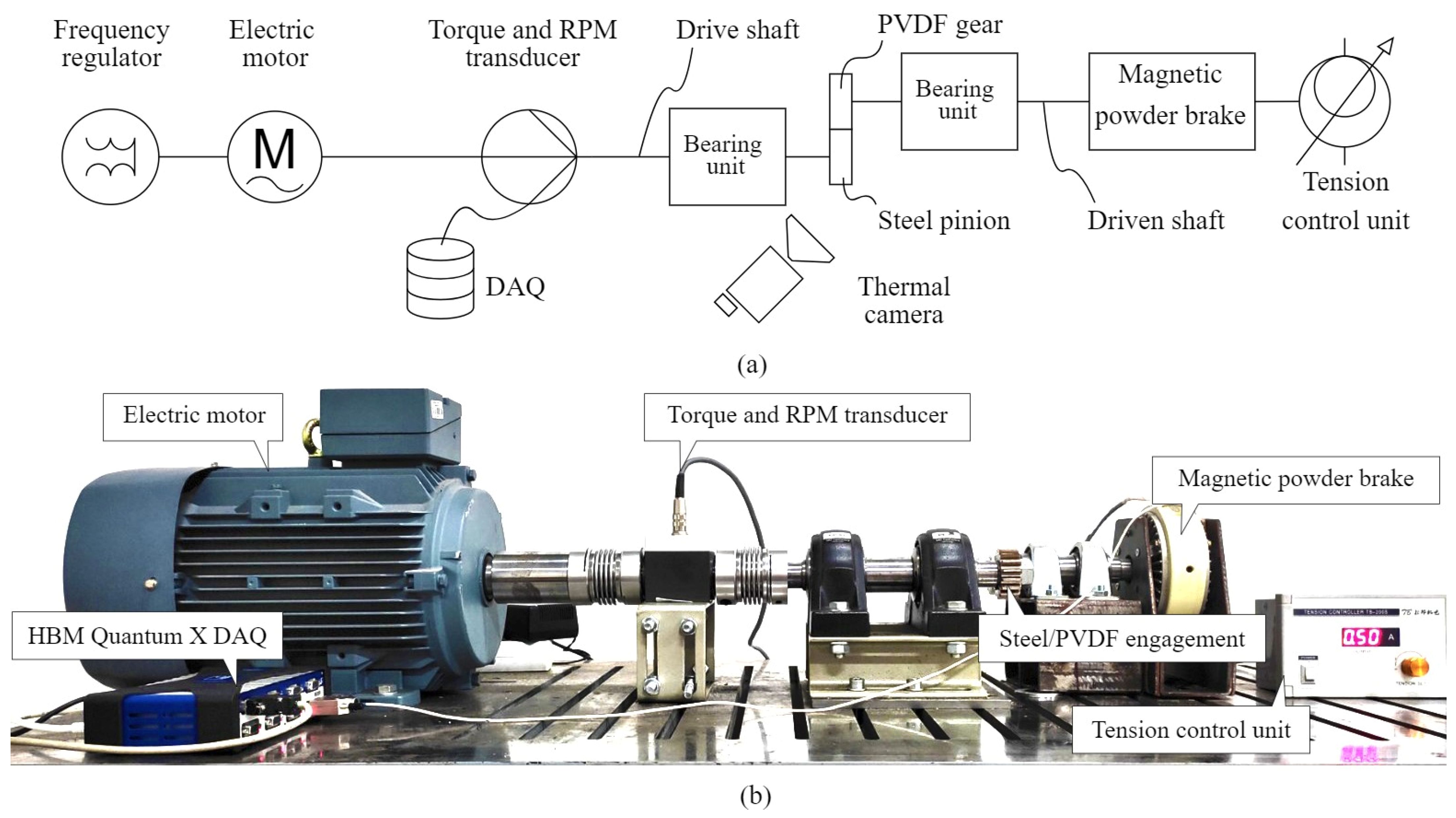
2.4. Experimental Settings

Experimental testing was conducted using a specially developed open-loop test rig (Figure 2a,b). PVDF gear samples were mated with steel pinions and subjected to dry friction conditions in a laboratory environment at 20 °C and constant humidity. The testing parameters, designed to mirror expected real-world operational conditions, included three load levels (4 Nm, 5 Nm, and 6 Nm) and a rotational speed of 1000 rpm. The reference load levels were also selected based on the gear geometry in real-life applications, with the specified values associated with the working regimes of gear pumps and conveyor systems. Even though gear geometry can be used at lower load levels, such a design would not meet the lightweight design requirements, as the rotary motion transmission could be accomplished with smaller gears. Each test under these conditions was repeated three times to obtain statistically reliable data for precise engineering and design. The open-loop configuration was powered by a three-phase electric motor (Marathon Electric HJA-IE2 132 M, Regal Rexnord Corporation, Wausau, WI, USA), which serves as a power supply to an open-loop configuration.
The rotational speed of the electric motor, controlled by a frequency regulator (En600-4 T 0075G/110P, Shenzhen Encom Electric Technologies CO, Shenzhen, China), is transferred to the drive shaft (i.e., the steel gear) via elastic couplings and bearing units. The torque transducer (HBM T20WN T153040, Hottinger Baldwin Messtechnik GmbH, Darmstadt, Germany) is linked to the Quantum X DAQ used to monitor and acquire torque and rotational speed data. The polymer gear, in engagement with the steel pinion, is mounted on the driven shaft coupled to the magnetic powder brake (FZ-12-K TB-200S, Yun Duan, Taiwan, China), which is used to simulate load level, that is, precisely regulate torque, through a tension control unit. The bulk temperature increase in PVDF gear samples was monitored at the reference tooth root region with a thermal camera (FLIR A 700, FLIR Systems AB, Titisee, Täby, Sweden). The temperature of the reference region in the area of the tooth root of PVDF gears, presented in Figure 3a, was monitored with the 1-pixel marker designated in a thermal analysis software (FLIR Research Studio, ver. 2024.07.2, Teledyne Technologies Inc., Thousand Oaks, CA, USA), as shown in the thermal view in Figure 3b.

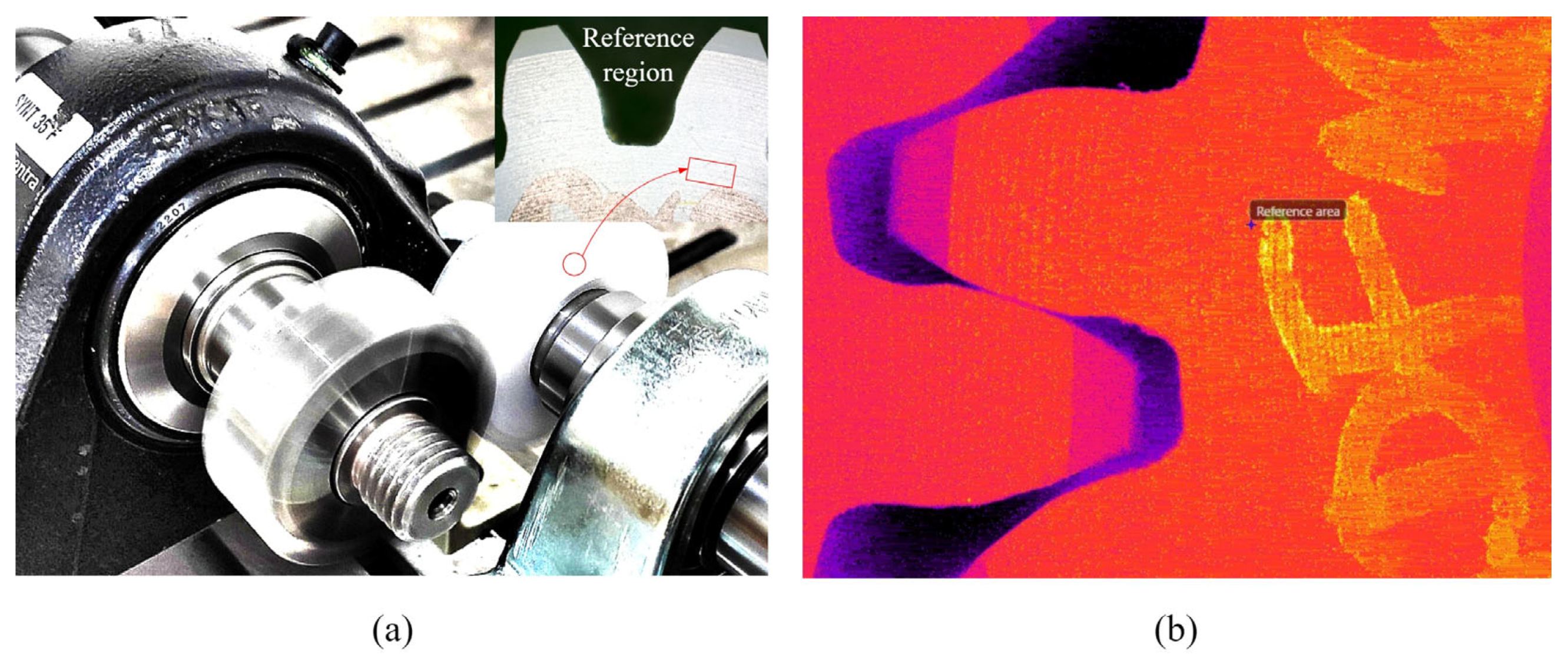
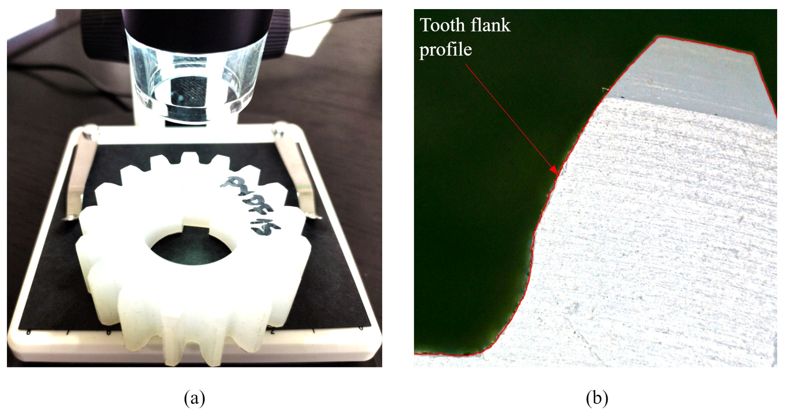
2.5. Capturing of the Tooth Profile

Digital processing of the tooth profile for PVDF gears was performed using a digital microscope (NB-MIKR-500, Transfer Multisort Elektronik, Łódź, Poland), i.e., employing the edge-recognition ability. In this way, worn-out tooth profiles can be digitized with a high accuracy of 10 µm and compared with the initial unworn involute geometry to establish wear-related data [56]. Optical processing of the geometry of the tooth flank was performed at 22 times magnification. The digital processing, using an optical microscope, is presented in Figure 4a, while Figure 4b presents the digitalized tooth profile.

2.6. Wear Analysis

The results of the digital processing of the PVDF gear samples are imported into PortableCapture Plus (version 3.1, Transfer Multisort Elektronik, Łódź, Poland) software for precise geometric measurements; that is, the differences between the worn-out profiles and the initial tooth geometry. The largest perpendicular distance between the profiles represents linear wear, W m , for calculating the wear coefficient, k w . Linear wear, W m , was determined for all the PVDF gear samples along the entire profile line at each load level. The wear coefficient, k w , was then calculated based on the VDI 2736 abrasive wear model, described by Equation (1):
k w = W m · b w · z · l F L 2 · π · T d · N L · H V
where b w is the standard face width, z is the teeth number, l F L is the profile line length, T d is the torque, N L is the number of operating cycles, and H V is the tooth loss. The tooth loss, H V , can be expressed by Equation (2):
H V = π · ( u + 1 ) z 2 · c o s β b · ( 1 ε 1 ε 2 + ε 1 2 + ε 2 2 )
where u is the gear ratio, z 2 is the number of teeth for PVDF gears, β b is the helix angle, and ε 1 , 2 are the partial radial contact ratios of the pinion and gear, respectively. The contact ratios, ε 1 , 2 , can be obtained by Equation (3):
ε 1 , 2 = z 1 , 2 2 · π · ( d a 1 , 2 d b 1 , 2 2 1 t a n α w t )
where z 1 , 2 is the number of teeth, d a 1 , 2 are the tip diameters, d b 1 , 2 are the base diameters, and α w t is an operating pressure angle. Finally, to calculate the wear coefficient according to the VDI 2736 abrasive wear model, the necessary profile line length, l F L , can be defined by the gear geometric parameters, as expressed by Equation (4):
l F L = 1 d b · [ ( d N a 2 ) 2 ( d N f 2 ) 2 ]
where d N a and d N f represent the active diameters of the tooth tip and root, respectively.

3. Results

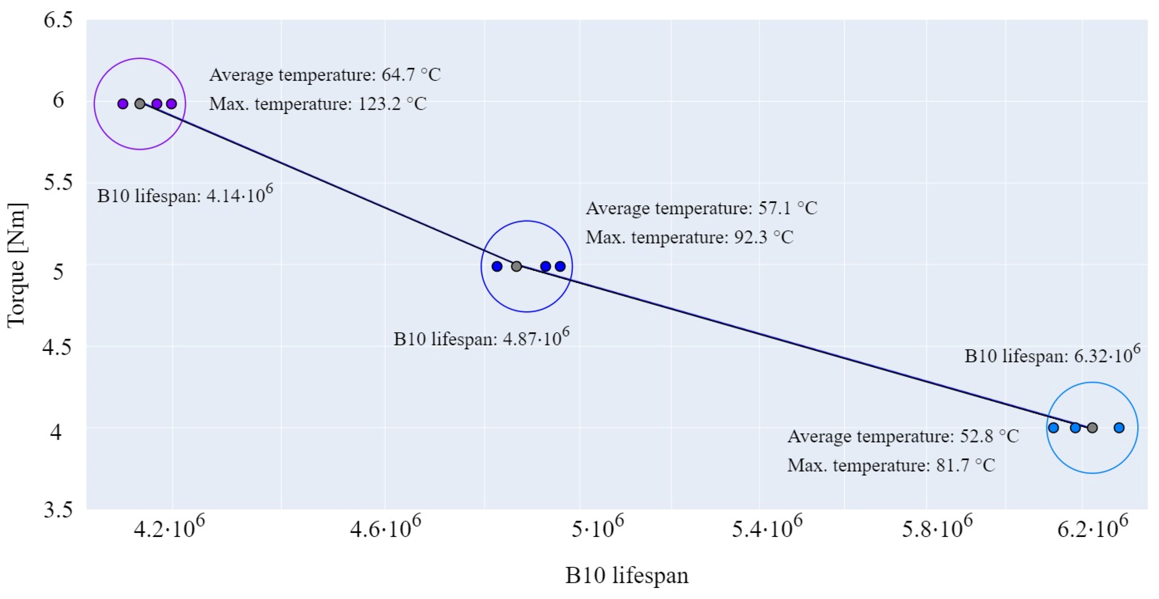
3.1. Correlation Between the Lifetime, Load Level, and Temperature

The lifetime results of the PVDF gear samples at reference load levels are presented in Figure 5. Lifetime data at each load level were generalized using the Weibull analysis, which can provide statistically relevant data for a smaller number of tests [57]. Using the Weibull distribution, data from three test repetitions at each load level formed the lifespan curve based on the 90% survival rate limit, commonly referred to as the B10 lifetime (the point at which 10% of components made of a specific material are expected to fail). As shown in Figure 5, higher load levels result in shorter lifetimes of PVDF gears, with a maximum B10 lifetime of 6.32 × 10⁶ cycles at the load level of 4 Nm. In addition, data on mean and maximum temperature values are provided to establish the correlation between the load level and the developed temperature.
As expected, the highest temperature of 123.2 °C was developed at the load level of 6 Nm, as the severity of contact, that is, the load-induced increase in the contact area, alters the sliding conditions, resulting in greater frictional losses and associated heat development. The relatively small difference of 4.3 °C in the average bulk temperatures between load levels of 4 Nm and 5 Nm can be explained by the prolonged lifetime at lower load levels, that is, the greater heat accumulation due to longer operating time. As noted from the results presented in Figure 5, besides the torque level, the developed temperature also has a crucial role in wear rate as thermal degradation alters friction coefficients and gear efficiency, resulting in changes in contact parameters, such as contact pressure and sliding conditions, which strongly influence the wear behavior. The latter will be described in more detail in the next section.

3.2. Wear Evaluation

To fully establish the correlation between the load level, the temperature developed in the steel/polymer engagements, and the wear rates at each reference load level, the wear coefficients were evaluated following the previously emphasized VDI 2736 model [19]. The worn-out tooth profiles used for the wear analysis were obtained from separate PVDF gear samples before the end of their operational service life, previously established by the Weibull reliability model. Separate PVDF gears were mandatory since any arbitrary stopping of the initial samples used for lifetime testing and their reuse would result in inaccurate wear analysis due to repeated cooling and heating of the gear samples, which would significantly disturb the thermal effects on the wear rate, i.e., once stopped, PVDF gear samples would partially experience the running-in phase with higher wear rates.
Each sample used for the wear analysis was measured at ten different profile points, starting from the root diameter to the tip diameter, with an even increment of 0.91 mm, to fully describe the wear mechanism of each tooth along the entire profile line. All the analyzed profiles were matched at the tooth tip point on the side of the unworn profile, assuming the same load–temperature deformation state due to equal testing conditions. Figure 6a presents the linear wear measurement procedure for the load level of 6 Nm after 4 × 10⁶ cycles. The value of 0.35 mm at the pitch diameter, as presented in Figure 6a, was obtained compared to the initial, i.e., reference tooth profile. Figure 6b presents the comparative view of the initial and worn-out profiles, i.e., the tooth profile degradation after 6.2 × 10⁶ and 4.8 × 10⁶ cycles at load levels of 4 Nm and 5 Nm, respectively. Due to transparency, the measurement of the linear wear is presented for the two profile points, extracted from the ten-point range, at the diameters of 45.31 mm and 56.09 mm.
As shown in Figure 6b, the linear wear, W m , amounts to 0.09 mm for both worn-out profiles at a diameter of 56.09 mm. At a diameter of 45.31 mm, the linear wear for the 4 Nm torque amounts to 0.11 mm, while, at the same diameter, the linear wear for the 5 Nm torque amounts to 0.239 mm. As shown in Figure 6a, the higher load level causes a more severe wear mechanism along the area of the tooth profile, except the tooth tip, which can be explained by the relatively small specific sliding of contact surfaces at the end of the engagement. Figure 6b gives a more comprehensive view of the advancement of the wear mechanism. The 4 Nm profile line shows that at the lower load levels, the maximum tooth degradation occurs in the tooth root area, which the contact mechanics can explain at the tooth root area, i.e., the more severe sliding conditions at the beginning of the engagement. As expected, the 5 Nm worn-out profile line shows greater wear progress along the entire profile line, with the engagement of more intensive wear being shifted to the addendum area and negligible changes in wear at the pitch diameter. The reason for such a progression of wear rate is reflected in changes in contact morphology, i.e., the cyclic changes in contact pressures at each wear cycle, that cause alterations in sliding conditions and contact parameters, with the worn-out surfaces experiencing a less severe stress state, and contact with more wear intensity being shifted to the other, i.e., unworn zones of the tooth flank. The linear wear, W m , was calculated for each PVDF sample at a reference load level as the mean value of all measurements. The linear wear, W m , of a single tooth flank, considering the profile points previously emphasized at ten specific tooth diameters, can be expressed by Equation (5):
W m = i = 1 n Δ L i · n 1
where Δ L i is the difference between the initial and worn-out profile at the i point, i.e., specific diameter, and n is the number of profile points used for measurement. Table 2 presents the parameters required to evaluate the wear and specified wear coefficient values at reference load levels.
The data on the evaluated worn coefficients, presented in Table 2, show an approximately linear growth in the wear rate following the reference load level, which fully corresponds to the B10 lifetime curve in Figure 5. As expected, higher load levels have more intense wear rates, since more severe load conditions cause surface strength. Additionally, the developed temperatures at the higher load levels, also presented in Figure 5, lead to the effect of thermal wear, that is, the increase in wear rate with the rise in the temperature.

3.3. Failure Mechanisms

To confirm the experimental settings in relation to the reference load levels, several PVDF gear samples were tested at a torque of 8 Nm. Due to higher load conditions, gear samples experienced temperature failure, i.e., thermal overload, followed by temperature-induced deformations, as presented in Figure 7a. Additionally, the wear life of the gears was significantly shorter compared to lower load levels. Therefore, the load level of 8 Nm exceeds the endurance limit of the PVDF gears with the associated geometric parameters, which agrees with the experimental settings. Figure 7b shows the tooth fracture propagating from the pitch line zone to the tooth root. The specific failure mechanism, shown in Figure 7b, occurred at the load level of 6 Nm after 4.22 × 10⁶ cycles. The tooth fracture was induced by the wear mechanism noticeable in the tooth root area, leading to compromised bending stiffness and load-induced deformations. The indicated deformation in the tooth root area results from both simultaneous loading and thermal effects on the compromised, i.e., worn-out, tooth cross-section, as the reduced area of the tooth root can no longer withstand the applied load.
Additionally, just before the tooth fracture occurs, the temperature rise reaches its peak, significantly impacting the temperature-dependent mechanical properties of the polymer material, leading to an increase in thermally induced deformation. Furthermore, the melted layers of the worn-out PVDF material were detected due to the temperature development at the engagement zone. Figure 7c presents the wear mechanism on the tooth flank at the 5 Nm load level with the uniform wear depth in the addendum and dedendum areas. The image also captures the layer removal, resulting from the shear mechanism, and the thermal influence on the worn-out material. The wear propagation along the tooth profile, presented in Figure 7c, is characteristic of the transition between the running-in and linear wear phases. The layer removal, presented in Figure 7c, perfectly describes the influence of thermal degradation on wear properties. The localized melting, which results in material removal, increases surface roughness and consequently accelerates the abrasive wear mechanism. The uniform wear mechanism of the PVDF tooth profile at the 4 Nm load level is presented in Figure 7d. The uniform wear distribution results from the preferable contact conditions—specifically, lower heat accumulation and lower load level —are characteristic of the PVDF polymer material. As shown in Figure 7d, there is an absence of thermal effects on the surface layers of the gear flanks, meaning that the temperature effects have little to no influence on the engagement analyzed, therefore reducing the transmission of the alterations in the rotary motion.
Polymer gear samples, presented in Figure 7, indicate several types of failure mechanisms at specific testing conditions. As each test at a specific load level was repeated three times, the occurrence of these failures can reveal the nature of the complex temperature-dependent material properties of polymer gears. Each sample, regardless of load level, experienced a thermal overload. However, the melting failure was only decisive for the 8 Nm level; therefore, 25% of the tested samples experienced pure thermal overload. The other 75% of samples experienced gradual thermal effects on the tooth flank areas, where the thermal effects on samples tested at 4 Nm can be accounted for only in late phases of engagement due to a sudden increase in temperature. The wear mechanism, with different wear rates at each load level, occurred at 75% of the tested samples, while the pitch point fracture occurred at 50% of the tested samples on corresponding torque levels of 5 Nm and 6 Nm—25% of samples tested at the 4 Nm load level experienced tooth root fracture. The specific deformation of the tooth root area, notable in Figure 7b, only occurs at the 6 Nm load level, i.e., 25% of the tested samples, meaning that the distortion of the root area corresponds to load level and developed bulk temperature. When it comes to analyzing failure modes, it is also very important to distinguish the complex nature of fatigue-related phenomena. The presented wear-induced changes, which lead to material loss over time, can be classified as fatigue wear. Even though wear and fatigue are distinct failure mechanisms, they are interconnected due to repeated loading cycle actuation over the tooth flank. However, as wear and fatigue behavior are strongly influenced by temperature increase, the thermal softening and the alterations in the viscoelastic effects of the tooth flank result in a reduction in the stiffness of polymer material and surface defects, such as thermal cracks, which act as stress concentrators, making the tooth flank more susceptible to wear, i.e., the temperature rise induces the so-called thermal wear.

4. Discussion

This research systematically investigates PVDF polymer gears, analyzing the mechanical properties, tribological parameters, and associated failure mechanisms under different load levels. Considering the lack of data on polymer gear design and the insufficient data in the current version of the VDI 2736 guidelines, designers must perform experimental testing by employing dedicated test rigs to simulate realistic operating conditions, therefore providing the necessary data for new gear design. The utilization of this experimental setup is usually based on different working principles, such as the open-loop configuration used in this study, and a conventional back-to-back configuration, more suitable for the investigations of lubricated engagements [58,59]. Nevertheless, the vital data on polymer gear endurance limits, operational lifetime, and overall performance under specific load levels can be obtained by employing any experimental arrangement. Additionally, as the polymer gears experience notable temperature changes, which influence their mechanical behavior, acquiring temperature data is mandatory to evaluate the coefficient of friction and the functional range of load levels at which the polymer material with specified gear geometry can be used. The relevant temperature data are usually obtained through non-destructive methods, i.e., by employing thermal cameras to monitor the data on temperature development at specific areas of interest.
The knowledge of the service life in steel/polymer engagements, i.e., in applications where the dominant failure mechanism is abrasive wear, requires data on wear coefficients, which is vital in the gear design process. The current version of the VDI 2736 provides very general data, only for POM and Polybutylene (PBT) materials, which are introduced only for specific polymer gear geometry, i.e., gears with a modulus of 1 mm, regardless of the operating conditions. Moreover, the data on wear coefficients presented in the VDI 2736 guidelines is obtained with pin-on-disc testing, which can lead to design uncertainty, i.e., overestimated wear properties of polymer gears, as established by other researchers in the field. Testing of real-scale gear geometry in laboratory conditions that simulate the actual operating loads represents a first step in the valid polymer gear design, and, more specifically, assessment of the wear coefficient. The methodology, which employs the optical methods, presented in this study, is suitable enough to determine the necessary wear coefficients with satisfying accuracy. The presented procedure can be refined even further by taking into account more profile points for the measurement of linear wear, at the expense of evaluation time, or by employing other technologies such as three-dimensional (3D) scanning that can be effectively used to acquire data on tooth flank surfaces, therefore providing many more points of interest that can be used to define the differences in wear rates in flank direction. Three-dimensional scanning enables the comparison of an ideal CAD model with a 3D-scanned model of a gear after experimental testing. This method allows for a more in-depth analysis of deformed gears, especially in cases where the entire gear body is deformed, not just the gear teeth.
The data on service life, which the Weibull reliability model generalized, indicate that polymer gears’ service life inversely varies with the load level. The temperature development, with values in Figure 5, shows a bulk temperature rise with increasing load level. The data on the bulk temperature, with the acquisition method presented in Figure 3b, give a general overview of the thermal state of polymer gears, which is sufficient for the complete expression of load–temperature relations and formal evaluation of the coefficient of friction. However, more advanced studies on the coefficients of friction and the development of temperature models in gear systems require data on the instantaneous, i.e., flash temperature located at the current rotational position of gears in engagement, which is hard to measure due to the moving area of contact at high rotational speeds. With the high-performance possibilities of the thermal camera used in this study, the latter could be partially implemented with more designated 1-pixel markers at specific engagement locations, thus making a measurement mistake due to the convective heat removal to the surrounding air [60].
The evaluated wear coefficients at reference load levels indicate that the wear resistance of the PVDF tooth flank surfaces decreases with higher load levels, i.e., the values of wear coefficients are directly proportional to the load levels, following a similar growing trend to the lifetime curve presented in Figure 5. Likewise, the correlation between the wear rate and thermal properties of the PVDF gear samples indicates that surface wear of PVDF gears is also directly proportional to bulk temperature increase. Evaluated wear coefficients of the PVDF samples at the reference load levels present valuable data for calculating flank strength, which can be of great use in optimizing the gear design process and further development of the VDI 2736 guidelines.
The analysis of failure mechanisms, presented in Figure 7, additionally emphasizes the complexity of the polymer gear design process, as multiple factors, including temperature-dependent material properties, gear geometry, load level, and type of engagement, cause gear failure. The complexity of the failure mechanisms is reflected in the fact that several failure mechanisms may occur simultaneously, as presented in Figure 7. The detailed analysis of the failure mechanisms of polymer gears, previously tested on dedicated rigs, allows for a better understanding of material performance and endurance limits under specific operating conditions. In this way, the development of a new gear drivetrain can result in significantly reduced time for the development of prototypes and gear products and the reduction in individual unit costs.
Even though the current study provides a detailed analysis of the applicability of the PVDF material in gear applications, there are some limitations which need to be addressed in future research. As the polymer gears will most likely perform in various exploitation conditions, a thorough analysis of variable and cyclic loading is necessary. Likewise, various environmental effects need to be considered. Additionally, the presented research treats wear mechanisms with typical load and thermal effects. These influencing factors can be divided by controlling the temperature during the tests, so the analyzed wear rate is only related to load.
As engineering trends move toward lightweight design, sustainable development, and precise engineering, future research on PVDF gears could be directed toward applying PVDF gears in adaptive tools with a detailed analysis of temperature-dependent mechanical properties, durability, and stability. Additionally, concerning the wear mechanisms and mechanical properties of the PVDF gears, exploration of the potential of 3D printed PVDF gears should be addressed.

5. Summary and Conclusions

Due to their economic viability and low mass density, polymeric materials are frequently employed to fabricate gears for responsible mechanisms. For theoretical design analysis, each gear may be idealized as a perfectly rigid body undergoing rotation about a spatially fixed axis, devoid of axial displacement. In this model, every point on the gear describes a circular trajectory perpendicular to and centered upon this axis. At any given time t, all points on tooth surfaces exhibit a uniform angular velocity ω(t) and direction of rotation. Nevertheless, actual gears made of polymers diverge from this idealized model in several respects: their inherent viscoelasticity and thermal expansion ability, the fact that their mounting may permit minor axial displacement of the rotational axis, their teeth manifest slight variations in geometry and spatial distribution, and their surfaces are not perfectly smooth. These deviations are critical and cannot be disregarded in the design of gear sets where operational failure could precipitate substantial losses. The principal conclusions derived from the conducted experimental investigation made with steel–PVDF gearwheels are as follows:
  • To credibly determine wear coefficients for new PVDF gear designs and predict their lifetime, real-scale testing under designed operating conditions is necessary, as it allows for precise measurement of the difference between initial and worn-out profiles. Additionally, detailed tooth failure analysis at specific loads enables the establishment of the endurance limits for the polymer gear material and its associated geometry.
  • The operational lifetime of polymer gears is inversely related to the applied load, while bulk temperature and flank surface wear exhibit a direct proportionality to the load level. This suggests that lower load levels result in more suitable tooth-to-tooth contact conditions, characterized by a uniform wear rate and reduced heat generation, as evidenced by the absence of thermal effects and a more uniform, less severe wear mechanism at the lowest tested load (4 Nm).
  • The endurance limits of the polymer gear material and associated geometry can be established with a detailed failure analysis at specific load levels.
  • The PVDF gears exhibited three main failure mechanisms: abrasive wear due to the hardness difference between the steel and polymer; thermal failure from heat buildup at higher loads (causing overload and deformation); and tooth fracture, triggered by wear in the tooth root area, reducing stiffness and leading to breakage under load lower than maximum.
  • This study proves that PVDF material is a suitable option for gear applications, providing new insights into the design process. This suggests that PVDF can be an alternative to traditional polymer materials used for gears. The beneficial mechanical and thermal properties significantly contribute to a higher lifespan than conventional polymer materials.
  • The polymer gear design process must account for various parameters only determined by experimental testing. By addressing these parameters, the complex behavior of polymer materials in sliding engagements, as shown in this research, which results in several fatigue-related and thermal failures that coincide, can be described.
  • The thermal degradation of PVDF polymer material strongly influences wear rate, as the changes in surface roughness alter the contact parameters, resulting in an increased wear rate.
  • The future applications of PVDF gears should be investigated in terms of reducing wear rates and corresponding temperatures, i.e., an extensive investigation of lubricated contact should be undertaken. Likewise, the presented gear geometry should be tested in a temperature-controlled environment.
The insights obtained from this study extend beyond the area of polymer gears to broader industrial fields concerning wear mechanisms, surface sliding, and durability of the PVDF material, such as adaptive tools in car assemblies and other adaptive assembly modules used in flexible manufacturing systems that require exact positioning and load resistance. Comparative investigations on gear manufacturing methods and corresponding wear and mechanical properties can be derived from this study to explore the possibility of using PVDF gears in the same modules and thoroughly responding to lightweight development.

Author Contributions

Conceptualization, E.M. and A.J.M.; methodology, E.M. and Ł.G.; software, E.M.; validation, Ł.G., M.S. and A.J.M.; formal analysis, M.D.; investigation, E.M.; resources, Ł.G., I.S. and M.D.; data curation, A.J.M.; writing—original draft preparation, E.M.; writing—review and editing, Ł.G., I.S., M.S. and A.J.M.; visualization, E.M.; supervision, Ł.G. and A.J.M.; project administration, Ł.G. and A.J.M.; funding acquisition, Ł.G. All authors have read and agreed to the published version of the manuscript.

Funding

This research received no external funding.

Institutional Review Board Statement

Not applicable.

Informed Consent Statement

Not applicable.

Data Availability Statement

The data presented in this study are available on request from the principal author.

Acknowledgments

We thank the Faculty of Mechanical Engineering of the University of Sarajevo for providing polymer gear samples and assisting in implementing the research. The topic of this article is closely aligned with that of Ilyas Smailov’s doctoral dissertation.

Conflicts of Interest

The authors declare no conflicts of interest.

References

  1. Radzevich, S.P. Dudley’s Handbook of Practical Gear Design and Manufacture; CRC Press: Boca Raton, FL, USA, 2021. [Google Scholar]
  2. Tavčar, J.; Cerne, B.; Duhovnik, J.; Zorko, D. A Multicriteria Function for Polymer Gear Design Optimization. J. Comput. Des. Eng. 2021, 8, 581–599. [Google Scholar] [CrossRef]
  3. Zorko, D.; Štiglic, J.; Černe, B.; Vukašinović, N. The Effect of Center Distance Error on the Service Life of Polymer Gears. Polym. Test. 2023, 123, 108033. [Google Scholar] [CrossRef]
  4. Zorko, D.; Kulovec, S.; Duhovnik, J.; Tavčar, J. Durability and Design Parameters of a Steel/PEEK Gear Pair. Mech. Mach. Theory 2019, 140, 825–846. [Google Scholar] [CrossRef]
  5. Kumar Singh, A. Siddhartha Thermal and Wear Behavior of Glass Fiber-Filled Functionally Graded Material-Based Polyamide 66 Spur Gears Manufactured by a Novel Technique. J. Tribol. 2018, 140, 21601. [Google Scholar] [CrossRef]
  6. Mao, K.; Greenwood, D.; Ramakrishnan, R.; Goodship, V.; Shrouti, C.; Chetwynd, D.; Langlois, P. The Wear Resistance Improvement of Fibre Reinforced Polymer Composite Gears. Wear 2019, 426–427, 1033–1039. [Google Scholar] [CrossRef]
  7. Tavcar, J.; Grkman, G.; Duhovnik, J. Accelerated Lifetime Testing of Reinforced Polymer Gears. J. Adv. Mech. Des. Syst. Manuf. 2018, 12, JAMDSM0006. [Google Scholar] [CrossRef]
  8. Yang, J.; Zhang, Y.; Li, R.; Lee, C.H. Temperature Control-Based Design of Variable Damping and Lightweight Gear Bodies. Int. J. Adv. Manuf. Technol. 2024, 131, 1807–1821. [Google Scholar] [CrossRef]
  9. Zorko, D.; Wei, P.; Vukašinović, N. The Effect of Gear-Manufacturing Quality on the Mechanical and Thermal Responses of a Polymer-Gear Pair. J. Comput. Des. Eng. 2024, 11, 195–211. [Google Scholar] [CrossRef]
  10. Zorko, D.; Demšar, I.; Tavčar, J. An Investigation on the Potential of Bio-Based Polymers for Use in Polymer Gear Transmissions. Polym. Test. 2021, 93, 106994. [Google Scholar] [CrossRef]
  11. Hriberšek, M.; Kulovec, S.; Toubal, L. Performance Evaluation of Biocomposite Gears Under Fatigue and Wear: Steel Drive Gear Versus Biocomposite Drive Gear and Biocomposite Drive Gear Versus Biocomposite Gear. Fatigue Fract. Eng. Mater. Struct. 2025, 48, 1768–1781. [Google Scholar] [CrossRef]
  12. Hribešek, M.; Kulovec, S. Design Optimization and Fatigue Evaluation of Wood Composite Gears. Proc. Socrat. Lect. 2024, 10, 158–166. [Google Scholar] [CrossRef]
  13. Muratović, E.; Muminović, A.; Delić, M.; Pervan, N.; Muminović, A.J.; Šarić, I. Potential and Design Parameters of Polyvinylidene Fluoride in Gear Applications. Polymers 2023, 15, 4275. [Google Scholar] [CrossRef]
  14. Matkovič, S.; Kalin, M. Effect of the Coefficient of Friction on Gear-Tooth Root Fatigue for Both Dry and Lubricated Running Polymer Gears. Tribol. Int. 2024, 194, 109525. [Google Scholar] [CrossRef]
  15. Marković, A.; Ivanović, L.; Stojanović, B. Characteristics, Manufacturing, and Testing Methods of Polymer Gears: Review. In Proceedings of the 32nd International Conference on Organization and Technology of Maintenance (OTO 2023), Osijek, Republic of Croatia, 12 December 2023; Springer Science and Business Media Deutschland GmbH: Berlin, Germany, 2024; Volume 866, pp. 269–282. [Google Scholar]
  16. Muratovic, E. Lifetime Testing of Polymer Gears. In Polymer Gears; Elsevier: Amsterdam, The Netherlands, 2025; pp. 603–620. [Google Scholar]
  17. Trobentar, B.; Kulovec, S.; Hlebanja, G.; Glodež, S. Experimental Failure Analysis of S-Polymer Gears. Eng. Fail. Anal. 2020, 111, 104496. [Google Scholar] [CrossRef]
  18. VDI 2736 Part 1; Thermoplastic Gear Wheels—Materials, Material Selection, Production Methods, Production Tolerances, Form Design. Verein Deutscher Ingenieure: Harzgerode, Germany, 2016.
  19. VDI 2736 Part 2; Thermoplastic Gear Wheels—Cylindrical Gears—Calculation of the Load—Carrying Capacity. Verein Deutscher Ingenieure: Harzgerode, Germany, 2016.
  20. VDI 2736 Part 3; Thermoplastic Gear Wheels—Crossed Helical Gears—Mating Cylindrical Worm with Helical Gear—Calculation of the Load Carrying Capacity. Deutscher Ingenieure: Harzgerode, Germany, 2016.
  21. VDI 2736 Part 4; Thermoplastic Gear Wheels—Determination of Strength Parameters on Gears. Deutscher Ingenieure: Harzgerode, Germany, 2016.
  22. Matkovič, S.; Pogačnik, A.; Kalin, M. Comparison between VDI 2736 Wear Calculation and Experimentally Obtained Results. In Proceedings of the International Conference on Gears 2019, Garching, Germany, 8–20 September 2019; pp. 1311–1322. [Google Scholar]
  23. Zhong, B.; Song, H.; Liu, H.; Wei, P.; Lu, Z. Loading Capacity of POM Gear under Oil Lubrication. J. Adv. Mech. Des. Syst. Manuf. 2022, 16, JAMDSM0006. [Google Scholar] [CrossRef]
  24. Hribersek, M.; Erjavec, M.; Hlebanja, G.; Kulovec, S. Durability Testing and Characterization of POM Gears. Eng. Fail. Anal. 2021, 124, 105377. [Google Scholar] [CrossRef]
  25. Liu, J.; Feng, K.; Su, Z.; Ren, B.; Liu, Y. Dimensional Deviations and Distortion Mechanism of Polymer Spur Gear Fabricated by Fused Deposition Modeling. J. Mater. Eng. Perform. 2024, 342, 3026–3035. [Google Scholar] [CrossRef]
  26. Radzevich, S.P.; Storchak, M. Advances in Gear Theory and Gear Cutting Tool Design; Springer: Cham, Switzerland, 2022. [Google Scholar]
  27. Muminović, A.J.; Bektašević, S.; Muratović, E.; Pervan, N.; Smajić, J.; Muminović, A.; Šarić, I.; Mešić, E.; Trobradović, M.; Delić, M. Service Life and Failure Analysis of Nylon, Polycarbonate, and IGUS I180 Polymer Gears Made by Additive Manufacturing. Machines 2025, 13, 5. [Google Scholar] [CrossRef]
  28. Muminovic, A.J.; Pervan, N.; Delic, M.; Muratovic, E.; Mesic, E.; Braut, S. Failure Analysis of Nylon Gears Made by Additive Manufacturing. Eng. Fail. Anal. 2022, 137, 106272. [Google Scholar] [CrossRef]
  29. Zhang, Y.; Mao, K.; Leigh, S.; Shah, A.; Chao, Z.; Ma, G. A Parametric Study of 3D Printed Polymer Gears. Int. J. Adv. Manuf. Technol. 2020, 107, 4481–4492. [Google Scholar] [CrossRef]
  30. Karupaiah, V.; Narayanan, V.; Nagarajan, R.; Ismail, S.O.; Mohammad, F.; Al-Lohedan, H.A.; Krishnan, K. Performance Evaluation of 3D-Printed ABS and Carbon Fiber-Reinforced ABS Polymeric Spur Gears. BioResources 2024, 19, 2796–2810. [Google Scholar] [CrossRef]
  31. Prajapati, S.K.; Gnanamoorthy, R. Surface Design of 3D-Printed Polyether Ether Ketone for Abrasive Wear Resistance. Tribol. Trans. 2024, 67, 235–246. [Google Scholar] [CrossRef]
  32. Kang, S. Improved Wear Resistance of PTFE/GF Reinforced PPS Polymer Gear for Actuator. In Proceedings of the Proceedings of the FISITA - Technology and Mobility Conference Europe, Barcelona, Spain, 12–15 September 2023; FISITA: Stortford, UK, 2023. [Google Scholar]
  33. Tunalioglu, M.S.; Agca, B.V. Wear and Service Life of 3-D Printed Polymeric Gears. Polymers 2022, 14, 2064. [Google Scholar] [CrossRef]
  34. Muratović, E.; Pervan, N.; Muminović, A.; Delić, M. A Contact Mechanics Model for Surface Wear Prediction of Parallel-Axis Polymer Gears. Polymers 2024, 16, 2858. [Google Scholar] [CrossRef]
  35. Ignatijev, A.; Glodež, S.; Kramberger, J. Computational Model for Analysing the Tooth Deflection of Polymer Gears. Polymers 2024, 16, 677. [Google Scholar] [CrossRef]
  36. Matkovič, S.; Pogačnik, A.; Kalin, M. Wear-Coefficient Analyses for Polymer-Gear Life-Time Predictions: A Critical Appraisal of Methodologies. Wear 2021, 480–481, 203944. [Google Scholar] [CrossRef]
  37. Evans, S.M.; Keogh, P.S. Wear Mechanisms in Polyoxymethylene Spur Gears. Wear 2019, 428–429, 356–365. [Google Scholar] [CrossRef]
  38. Landi, L.; Morettini, G.; Palmieri, M.; Benicchi, S.; Cianetti, F.; Braccesi, C. Studying the Performance of Reinforced Polymer Gear Wheels: Development of an Advanced Test Bench for Wear Analysis. Machines 2024, 12, 183. [Google Scholar] [CrossRef]
  39. Trobentar, B.; Hriberšek, M.; Kulovec, S.; Glodež, S.; Belšak, A. Noise Evaluation of S-Polymer Gears. Polymers 2022, 14, 438. [Google Scholar] [CrossRef]
  40. Černe, B.; Petkovšek, M.; Duhovnik, J.; Tavčar, J. Thermo-Mechanical Modeling of Polymer Spur Gears with Experimental Validation Using High-Speed Infrared Thermography. Mech. Mach. Theory 2020, 146, 103734. [Google Scholar] [CrossRef]
  41. Singh, P.K.; Siddhartha; Singh, A.K. An Investigation on the Thermal and Wear Behavior of Polymer Based Spur Gears. Tribol. Int. 2018, 118, 264–272. [Google Scholar] [CrossRef]
  42. Rohrmoser, A.; Bode, C.; Schleich, B.; Hagenah, H.; Wartzack, S.; Merklein, M. Influence of Metal Gear Tooth Geometry on Load and Wear within Metal-Polymer Gear Pairs. Appl. Sci. 2022, 12, 270. [Google Scholar] [CrossRef]
  43. Pogacnik, A.; Beermann, S. Measuring Permissible Root/Flank Stress of Plastic Gears According to the VDI 2736-4. In Proceedings of the VDI Gear Conference 2017, Garching/Munich, Germany, 13–15 September 2017; Volume 2017, pp. 140–151. [Google Scholar]
  44. ISO 1183; Plastics—Methods for Determining the Density of Non-Cellular Plastics—Part 1: Immersion Method, Liquid Pycnometer Method and Titration Method. ISO: Geneva, Switzerland, 2019.
  45. ISO 527-2; Plastics—Determination of Tensile Properties—Part 2: Test Conditions for Moulding and Extrusion Plastics. ISO: Geneva, Switzerland, 2012.
  46. ISO 11359; Plastics—Thermomechanical Analysis (TMA)—Part 2: Determination of Coefficient of Linear Thermal Expansion and Glass Transition Temperature. ISO: Geneva, Switzerland, 2021.
  47. DIN 52612; Tesing of Thermal Insulating Materials; Determination of Thermal Conductivity by Means of the Guarded Hot Plate Apparatus; Conversion of the Measured Values for Building Applications. German Institute for Standardization: Berlin, Germany, 1984.
  48. ISO 3146; Plastics—Determination of Melting Behaviour (Melting Temperature or Melting Range) of Semi-Crystalline Polymers by Capillary Tube and Polarizing-Microscope Methods. ISO: Geneva, Switzerland, 2022.
  49. DIN 53765; Testing of Plastics and Elastomeres; Thermal Analysis; DSC-Method. German Institute for Standardization: Berlin, Germany, 1994.
  50. ISO 11357; Plastics—Plastics—Determination of Hardness-Part 1: Ball Indentation Method. ISO: Geneva, Switzerland, 2021.
  51. Radzevich, S.P. Theory of Gearing; U.S. Government Printing Office: Washington, DC, USA, 2022.
  52. Alharbi, K.A.M. Wear and Mechanical Contact Behavior of Polymer Gears. J. Tribol. 2019, 141, 011101. [Google Scholar] [CrossRef]
  53. Geng, Z.; Chen, M.; Wang, J.; Xia, Y.; Kong, Y.; Xiao, K. Nonlinear Dynamic Analysis of a Spur Gear Pair System with Wear Considering the Meshing Position. Lubricants 2024, 12, 25. [Google Scholar] [CrossRef]
  54. Shen, Z.; Qiao, B.; Yang, L.; Luo, W.; Yang, Z.; Chen, X. Fault Mechanism and Dynamic Modeling of Planetary Gear with Gear Wear. Mech. Mach. Theory 2021, 155, 104098. [Google Scholar] [CrossRef]
  55. ISO 53 A.; Cylindrical Gears for General and Heavy Engineering—Standard Basic Rack Tooth Profile. ISO: Geneva, Switzerland, 1998.
  56. Hlebanja, G.; Hriberšek, M.; Erjavec, M.; Kulovec, S. Advanced Lifetime Tests of Plastic Gears with E- and S-Geometry. In Mechanisms and Machine Science; Springer: Dordrecht, The Netherlands, 2021; Volume 101, pp. 427–444. [Google Scholar]
  57. Kızılersü, A.; Kreer, M.; Thomas, A.W. The Weibull Distribution: A Handbook; CRC: Boca Raton, FL, USA, 2008. [Google Scholar]
  58. Herzog, C.; Wolf, M.; Schubert, D.; Drummer, D. In Situ Investigation of the Influence of Varying Load Conditions on Tooth Deformation and Wear of Polymer Gears. Forsch. im Ingenieurwesen 2022, 86, 545–555. [Google Scholar] [CrossRef]
  59. Kunishima, T.; Nagai, Y.; Bouvard, G.; Abry, J.C.; Fridrici, V.; Kapsa, P. Comparison of the Tribological Properties of Carbon/Glass Fiber Reinforced PA66-Based Composites in Contact with Steel, with and without Grease Lubrication. Wear 2021, 477, 203899. [Google Scholar] [CrossRef]
  60. Roda-Casanova, V.; Sanchez-Marin, F.; Martinez-Cuenca, R. Convective Heat Transfer Modelling in Dry-Running Polymer Spur Gears. Int. J. Mech. Sci. 2023, 241, 107927. [Google Scholar] [CrossRef]
Figure 1. Manufacturing of the PVDF gear samples: (a) profile hob cutter; (b) final gear sample.
Coatings 15 00800 g001
Figure 2. Test rig configuration: (a) schematic view; (b) configuration appearance.
Coatings 15 00800 g002
Figure 3. Temperature monitoring: (a) reference region; (b) thermal view with the 1-pixel marker.
Coatings 15 00800 g003
Figure 4. Optical tooth profile analysis: (a) digital processing; (b) edge recognition.
Coatings 15 00800 g004
Figure 5. B10 lifetime in cycles for the tested PVDF gear samples.
Coatings 15 00800 g005
Figure 6. Wear evaluation: (a) comparison of the initial and worn-out profile after 4 × 10⁶ cycles at 6 Nm load level; (b) comparison of the initial and worn-out profiles after 6.2 × 10⁶ and 4.8 × 10⁶ cycles at load levels of 4 Nm and 5 Nm, respectively.
Coatings 15 00800 g006
Figure 7. Failure mechanisms of the PVDF gears: (a) load-induced thermal overload; (b) wear-induced tooth fracture; (c) wear mechanism with layer removal; (d) uniformly worn-out tooth profile.
Coatings 15 00800 g007
Table 1. Geometric properties of PVDF gears.
ParameterValue
ProfileInvolute, ISO 53 A [55]
Module3 mm
Number of teeth17
Pressure angle20°
Face width20 mm
Profile shift coefficient−0.1 mm
Pitch diameter51 mm
Tip diameter57 mm
Root diameter44.4 mm
Base diameter47.92 mm
Base tangent length17.4 mm
Table 2. Evaluated wear coefficients and associated calculation parameters.
Load Level (Nm) W m (mm) b w (mm) z (-) l F L (mm) N L (106) H V (-) k w (10−6 mm3/Nm)
40.15920176.676.20.6327.72
50.2394.810.98
60.351412.62
Disclaimer/Publisher’s Note: The statements, opinions and data contained in all publications are solely those of the individual author(s) and contributor(s) and not of MDPI and/or the editor(s). MDPI and/or the editor(s) disclaim responsibility for any injury to people or property resulting from any ideas, methods, instructions or products referred to in the content.

