1. Introduction
Road transport is one of the main contributors to global greenhouse gas (GHG) emissions, making it a priority sector in decarbonization strategies [
1,
2]. In Europe, initiatives such as the European Green Deal and the 2030 Agenda have established ambitious targets aimed at reducing emissions and improving energy efficiency. In this context, the electrification of road infrastructure through dynamic wireless charging technologies, such as Dynamic Wireless Power Transfer (DWPT), has emerged as a promising solution to support the transition toward more sustainable and resilient mobility systems.
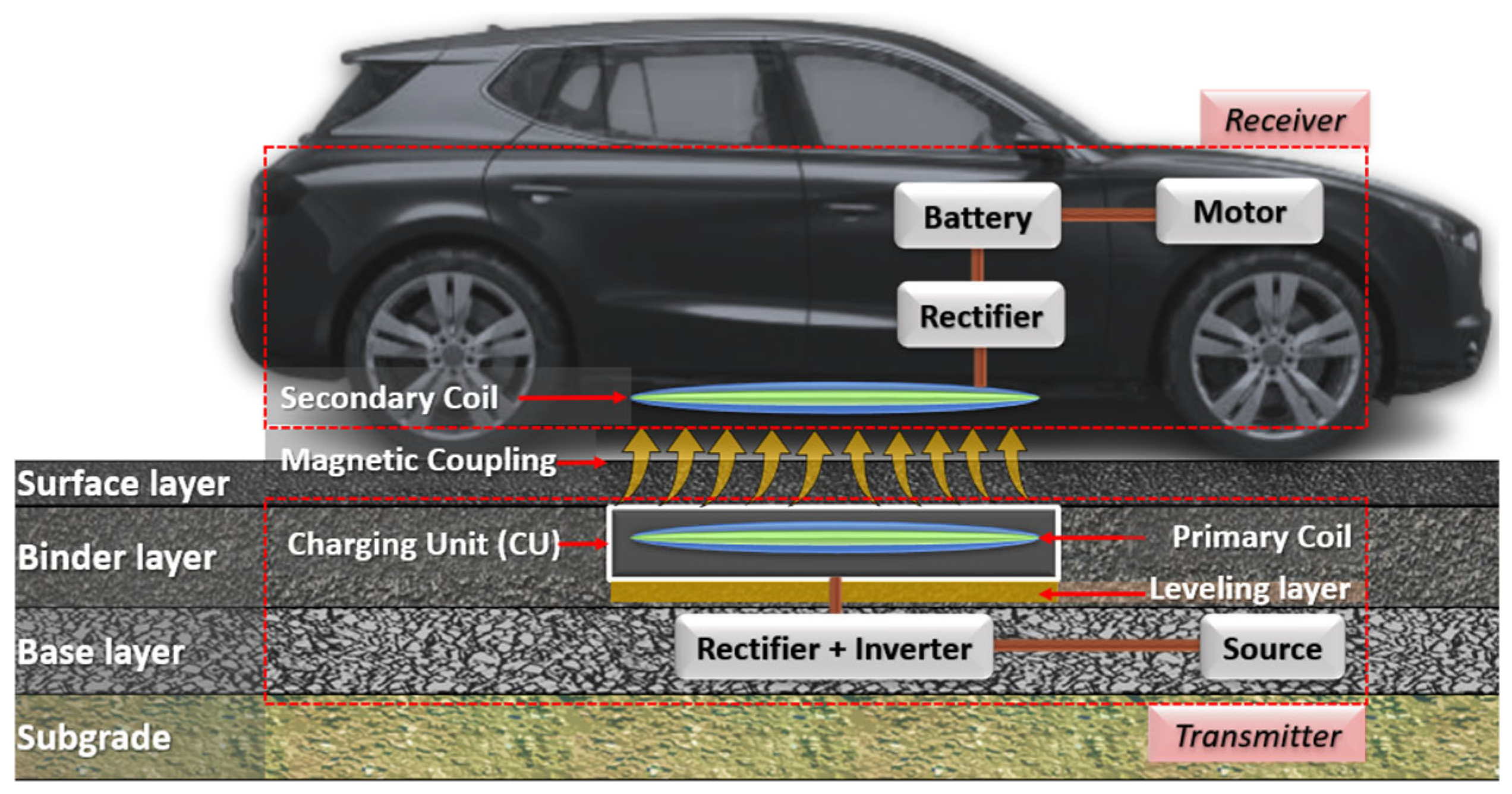
Among WPT systems, Dynamic Wireless Power Transfer (DWPT) stands out for its ability to continuously charge electric vehicles (EVs) while in motion, thereby reducing battery size requirements and minimizing vehicle downtime due to stationary charging [
3,
4,
5,
6]. DWPT relies on magnetic coupling between a primary coil embedded in the pavement and a secondary coil installed on the vehicle, enabling contactless energy transfer [
7,
8,
9] (
Figure 1).
Several international projects have demonstrated the technical feasibility of DWPT under real-world conditions, including OLEV (South Korea), Electreon (USA, Israel, etc.), FABRIC (Europe), Smartroad Gotland (Sweden), Arena del Futuro (Italy), and INCIT-EV (France) [
7,
8,
9]. In Spain, the CARDHIN project explored inductive charging solutions for electric vehicles [
10]. However, these developments have also revealed the structural complexity of integrating charging units (CUs) within pavement layers, as they alter the mechanical continuity, generate material interfaces, and disrupt the geometric homogeneity of the multilayer system.
The integration of DWPT technologies requires precise characterization of materials, traffic conditions, and interface bonding, as inadequate evaluation may compromise pavement durability. In Spain, pavement design follows National Standard 6.1-IC “Pavement Sections” [
11], which adopts a mechanistic–empirical methodology based on Burmister’s multilayer elastic theory. This framework assumes that materials are homogeneous, isotropic, and linearly elastic [
11,
12]. However, pavement electrification introduces significant geometric modifications, such as the insertion of charging units (CUs) through trenches, creating non-standard interfaces, inducing local stiffness discontinuities, and modifying stress paths under traffic loading.
Given the limitations of conventional methods, the Finite Element Method (FEM) has become a widely accepted tool. Recent studies have implemented elastic [
13], viscoelastic, and viscoplastic damage-based FEM formulations [
14], as well as coupled thermomechanical models incorporating environmental effects [
15,
16,
17]. Granular layers and subgrades have been modeled as elastic or stress-dependent nonlinear materials [
18]. At the same time, embedded components (CUs, encapsulation, coils) are commonly represented as linear elastic solids under different interface conditions [
19].
Notable examples include the work of Chen et al. [
20], who analyzed embedded CUs in concrete slabs under dynamic loading, and the INCIT-EV project [
16], which employed coupled thermo-viscoelastic models to assess the influence of climate and inductive heating. Nodari et al. [
21] also investigated the fatigue and rutting performance of pavements with embedded CUs, considering various geometries and thermal loading conditions.
Despite these advances, no previous studies have analyzed the structural performance of DWPT-integrated pavements within the framework of Spanish pavement typologies, particularly for semiflexible and semirigid sections defined by Standard 6.1-IC. This lack of context-specific modeling limits the transferability of international findings and hinders the development of tailored guidelines for national deployment.
In response, this study presents a comparative structural analysis between conventional and electrified pavement sections using multilayer elastic models and three-dimensional FEM simulations. While focused on the Spanish road network, the methodology and findings apply to any context that employs similar pavement typologies. The aim is to identify the mechanical effects of CU integration and propose engineering criteria to ensure the efficient and durable implementation of DWPT systems in national and international contexts.
3. Materials and Methods
To compare the structural behavior of conventional and electrified pavements with embedded Dynamic Wireless Power Transfer (DWPT) systems, a dual approach was adopted, combining multilayer mechanistic–empirical modeling and three-dimensional Finite Element Method (FEM) simulations. The objective was to evaluate the distribution of stresses and strains under different traffic levels and subgrade conditions, as defined in the Spanish Pavement Design Standard 6.1-IC. This regulation classifies heavy traffic into four levels (T00 to T2) based on the average daily number of heavy vehicles, and subgrade quality into three classes (E1 to E3) based on its bearing capacity, typically expressed in terms of deformation modulus.
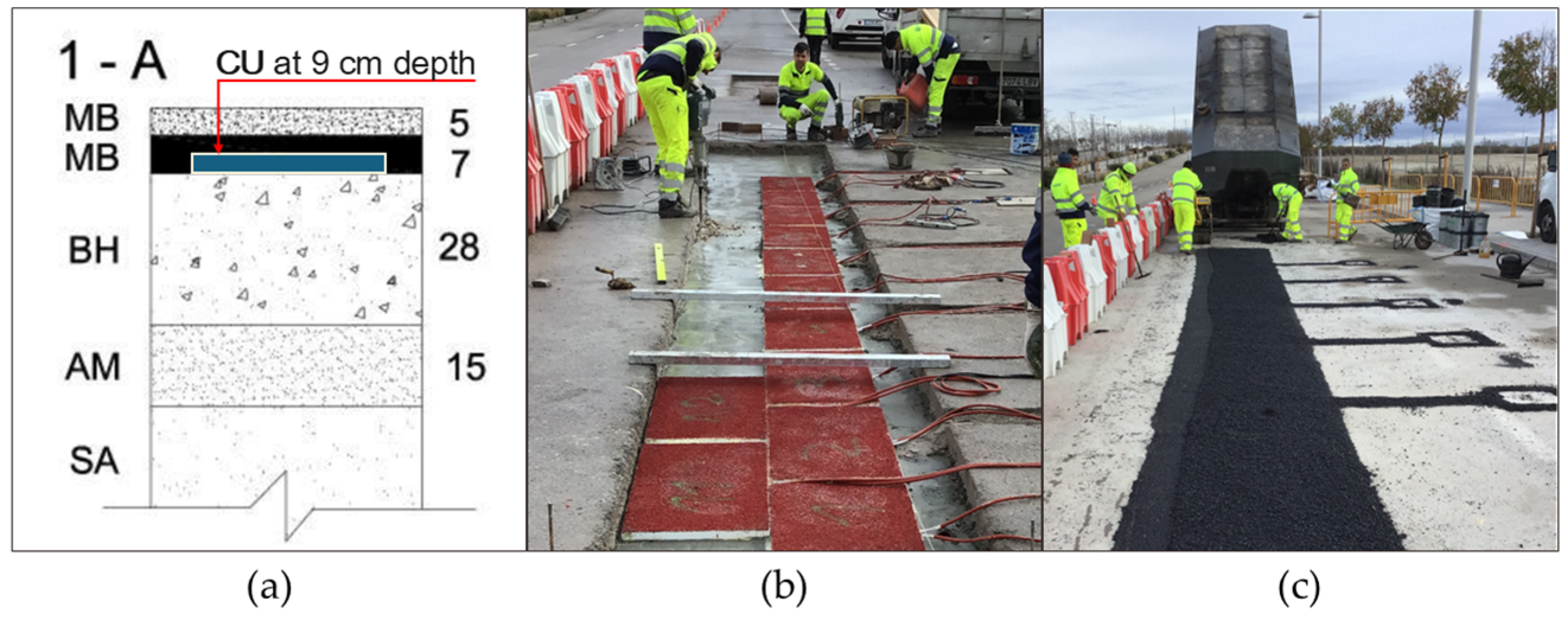
As a reference configuration, the experimental test section constructed in Madrid within the framework of the CARDHIN project—Dynamic Inductive and Hydrogen Charging for Electric Vehicles Based on Renewable Sources (Project No. MIG-20201042)—was selected (
Figure 2). The project was co-funded by the “MISIONES” Program of the Centre for the Technological Development and Innovation (CDTI) of the Spanish Government. The pilot section was constructed using a Type A-7 composite pavement, in accordance with the Urban Development Construction Standards of the Madrid City Council, and designed for heavy traffic conditions (AADT > 4000 heavy vehicles/day). Section 1-A comprises a 5 cm surface course and a 7 cm binder course, both composed of asphalt mixtures (MB), placed over a 28 cm hydraulic base (BH), followed by a 15 cm layer of bedding sand (AM), and underlain by natural soil (SA). This multilayer configuration meets the structural requirements for high-traffic applications and is well-suited for integrating WPT systems.
Multilayer models were developed for both the conventional and the electrified pavement designs, incorporating the geometry of the charging unit (CU) and its interaction with the surrounding pavement layers. These models were implemented using ALIZE 1.3.0 and ANSYS Mechanical 2025 R1 software, enabling the quantification of the structural effects introduced by the WPT system components under representative loading scenarios.
The geometric and installation characteristics of the charging units—including dimensions, encapsulation, depth, and layout—were directly based on the CARDHIN project specifications. This configuration was consistently applied across all electrified pavement sections analyzed, enabling a homogeneous comparison with their conventional counterparts.
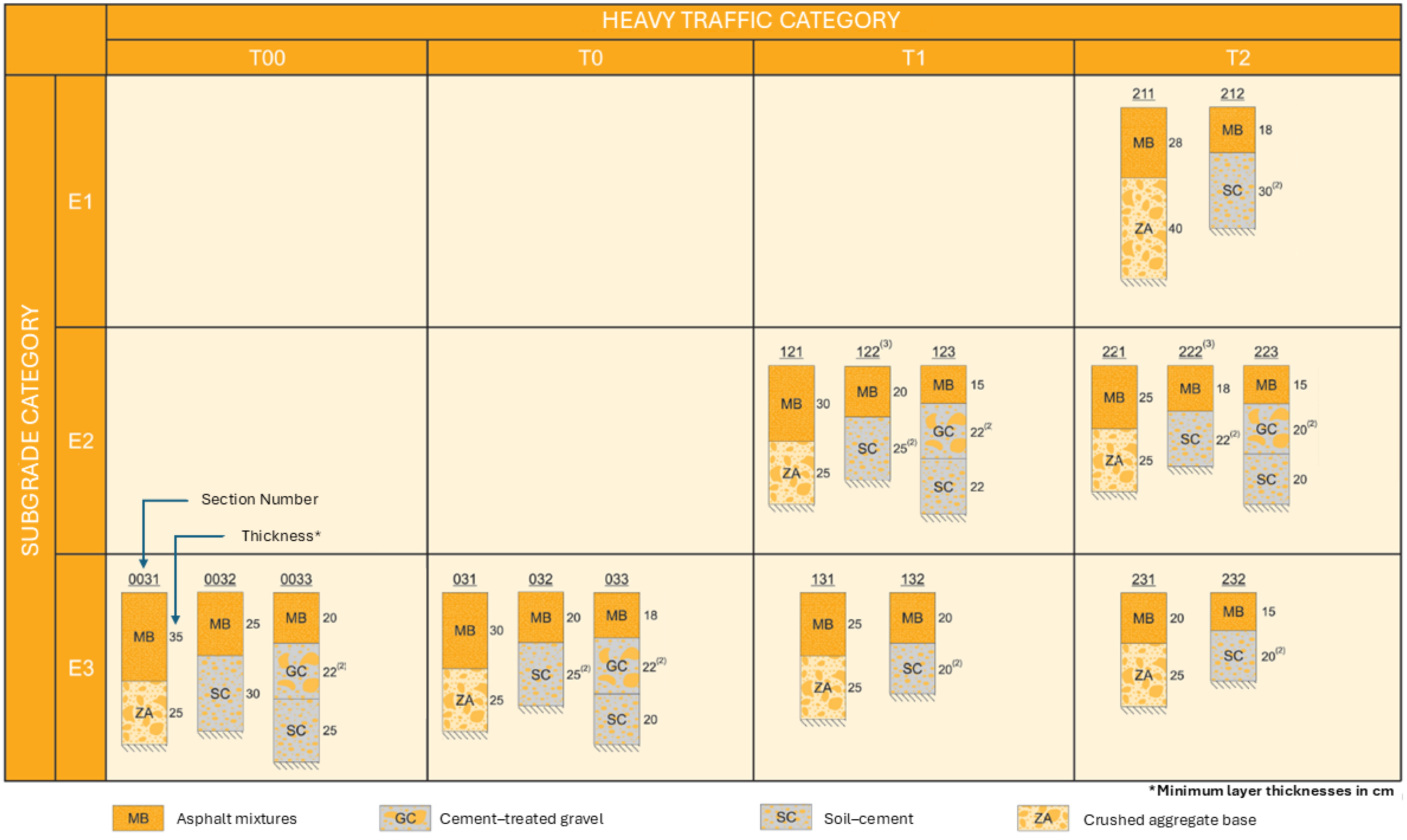
To broaden the applicability of the study, semiflexible and semirigid pavement sections, as defined in Spain’s Standard 6.1-IC “Pavement Sections”, were selected. Rigid pavements—rarely used in Spain—and those corresponding to low-traffic categories (T31–T42, with fewer than 800 heavy vehicles per day) were excluded, as such low traffic volumes do not justify the implementation of WPT systems.
Figure 3 summarizes the configurations considered.
The simulation process was conducted in two phases. In the first phase, an elastic finite element model (FEM) was developed for conventional pavement sections, and the results were validated against traditional multilayer structural design methods. In the second phase, a three-dimensional model was implemented, incorporating charging units (CUs) to simulate their integration into the pavement structure.
This progressive approach enabled a more detailed analysis of the effects of CUs on the overall structural response and the accumulation of damage under repeated loading. The results provide a technical basis for evaluating the feasibility of using existing pavement sections to accommodate DWPT systems and for identifying the structural adjustments needed for their effective integration in future updates to Spanish pavement design regulations.
3.1. Geometry Definitions
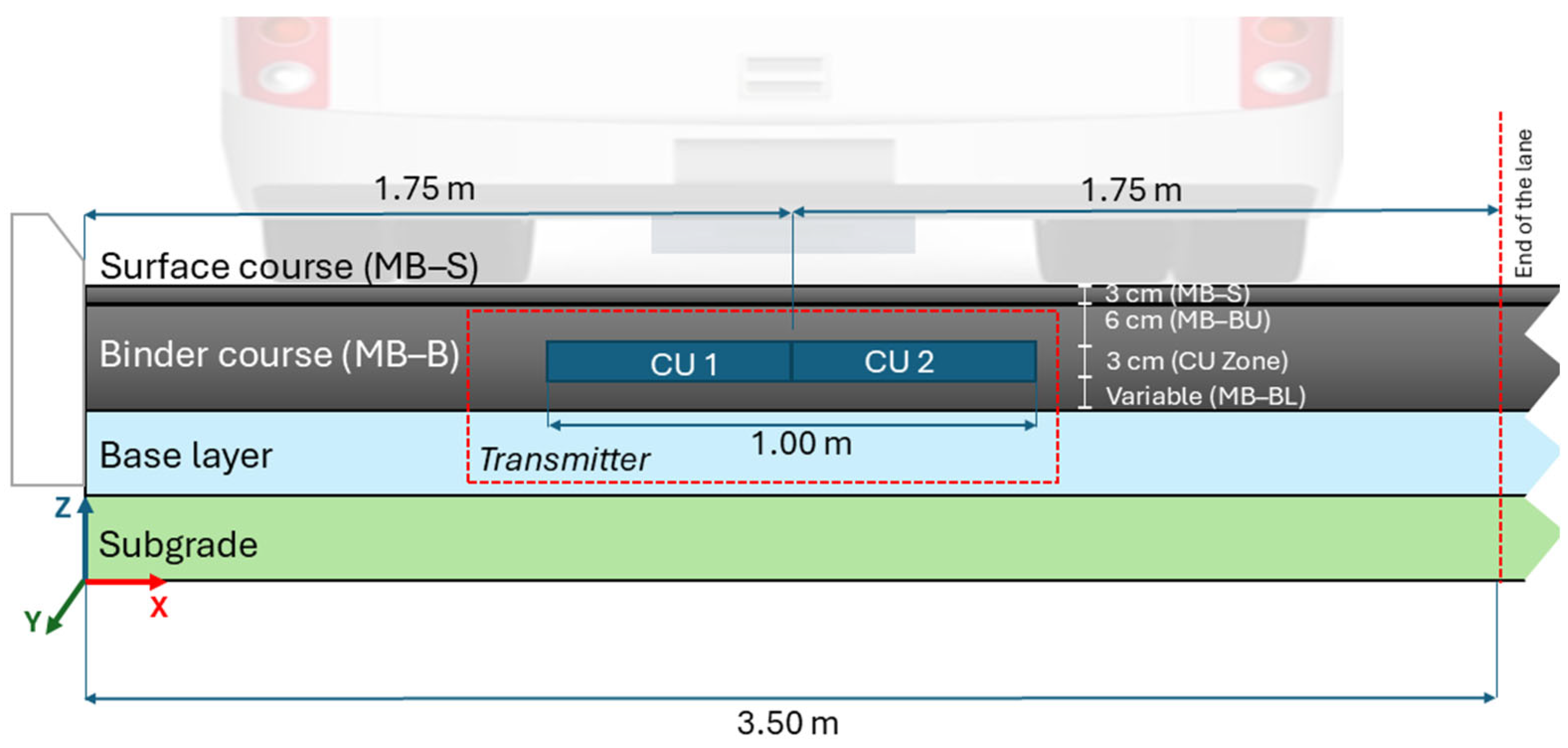
The model geometry was defined based on a standard pavement section for medium-to-heavy traffic, following Spain’s Pavement Design Standard 6.1-IC. In accordance with this standard, all asphalt layers are generally designated as MB (Mezcla Bituminosa), regardless of their specific structural function. However, for clarity in this study, the asphalt layers are referred to as MB-S (surface course) and MB-B (binder course).
In the electrified pavement configurations, where the charging unit (CU) is embedded within the binder course, this layer is further subdivided into an upper binder layer (MB-BU) and a lower binder layer (MB-BL), corresponding to the segments located above and below the CU, respectively. Specifically, the 3 cm thickness of the CU was accommodated by adjusting the upper portion of the binder course (MB-B), resulting in a 6 cm upper binder layer (MB-BU) placed above the CU, and the CU (3 cm thick) embedded directly beneath it. The remaining binder course, located below the CU (MB-BL), varied by section, with total MB-B thicknesses ranging from 12 cm to 32 cm. Although the overall thickness was maintained, reducing the upper binder layer (MB-BU) to 6 cm may affect the surface response. This is discussed in the Results and Discussion section.
This configuration replicates the construction details of the CARDHIN pilot section, in which the inductive coil was installed at a depth of 9 cm from the pavement surface and was applied uniformly across all electrified pavement models. All other pavement layers remained unchanged between the conventional and electrified configurations (
Figure 4 and
Figure 5,
Table 1). The base layer materials included crushed aggregate (ZA), cement–soil (SC), and cement-treated gravel (GC), as defined in the Spanish road pavement catalogue.
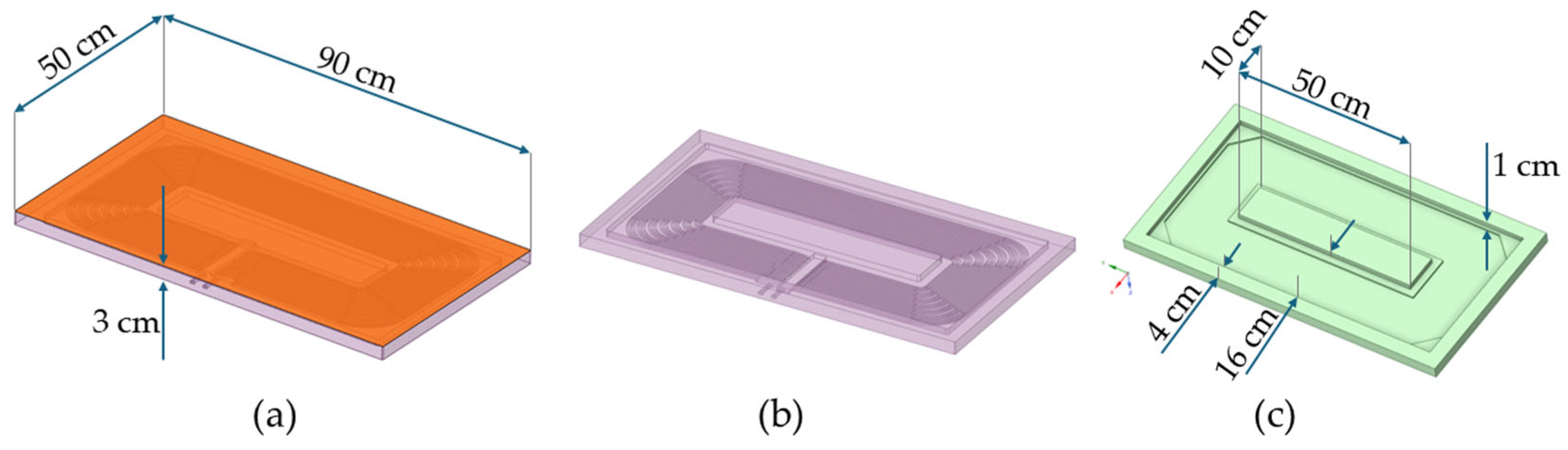
The CUs, with actual dimensions of 90 cm × 50 cm × 3 cm, were represented using simplified geometry in ANSYS SpaceClaim, modeling a 3.50 m wide and 0.90 m long cross-section (
Figure 6). This length corresponds to one CU, treated as a repeating module in the longitudinal direction; therefore, symmetry boundary conditions were applied at the front and rear ends of the model.
The domain was subdivided into three zones (1a, 2, and 1b) based on the position of the applied load, allowing for local mesh refinement. In all cases, the CUs were arranged in pairs along the centerline of the lane.
Regarding boundary conditions, it was assumed that, beyond a certain depth, traffic-induced deflections become negligible, and deformation is confined to the upper layers of the pavement. This assumption is supported by multilayer elastic theory, which demonstrates that vertical stress and deflection decrease rapidly with depth, particularly below the bound layers. This approach is widely used in pavement mechanics and has been consistently applied in FEM studies for structural analysis of pavement systems [
22,
23,
24]. Accordingly, a fixed support condition (UX = UY = UZ = 0) was applied at the base of the model to restrict vertical and lateral displacements. At the pavement edge (curb), UX = 0 was imposed to simulate the lateral confinement provided by the curb. At the same time, UY and UZ were left free to allow longitudinal slip and vertical settlement.
Symmetry boundary conditions were applied in the Y direction at the front and rear faces of the model to represent the continuity of a longer traffic lane with multiple embedded charging units (CUs), without compromising the structural validity of the representative model.
The charging units (CUs) have external dimensions of 90 cm in length, 50 cm in width, and 3 cm in thickness. Their housing is rectangular, with a closed top face and an open bottom that allows integration with the surrounding asphalt. Internally, a central longitudinal core provides structural rigidity, while the electrical coil is embedded in polydimethylsiloxane (PDMS), a silicone-based polymer with very low stiffness (E < 3 MPa), which serves as an encapsulant between the core and the housing walls.
In the FEM simulations, the CU was represented as a hollow body with rigid external walls and an open base, omitting the low-stiffness PDMS region for simplicity. This approach captures the structural effect of the CU’s geometry without modeling the internal coil.
Figure 6a,b depict the actual CU geometry used in the CARDHIN pilot section, while
Figure 6c shows the simplified version adopted for numerical modeling. In all configurations, CUs were placed in pairs, centered along the lane axis.
3.2. Material Definitions
The materials used in this study were selected based on their mechanical properties, which are essential for accurately representing the structural response of both conventional and electrified pavement sections. Asphalt mixtures were characterized using high-precision laboratory testing (
Table 2), while values for other layers were estimated from indirect testing methods or standard design guidelines [
11,
12,
25].
The asphalt mixtures were characterized using resilient modulus values (EBi) obtained in accordance with European Standard EN 12697–26. Four samples, labeled EB1 to EB4, were tested for each type of asphalt mixture. For the surface course (MB-S), a gap-graded SMA8 mixture was used, with a maximum aggregate size of 8 mm, designed to provide high wear resistance and good rutting stability. For the intermediate layers (MB-B), a semi-dense AC16 mixture with a maximum aggregate size of 16 mm was selected, as it is suitable for providing structural support and facilitating the transition between layers.
The base layers—including crushed aggregate, cement-treated soil, and cement-treated gravel—were assigned mechanical properties based on standardized values defined in Spanish regulations, specifically Standard 6.1-IC and ICAFIR (Junta de Andalucía). For the subgrade, the compressibility modulus from the second load cycle (E
v2) was used, as determined by plate load testing (UNE 103808:2006), and categorized according to the structural classification levels E1, E2, and E3, as shown in
Table 3.
The Young’s modulus of the subgrade (
Es) was calculated from the
Ev2 value using the following expression:
where
ν is Poisson’s ratio.
Finally, the material selected for the charging unit (CU) housing was a PBT/PET polymer blend, combining the mechanical advantages of two thermoplastic polyesters. This blend is a thermoplastic with a tensile modulus of 2500 MPa, a tensile strength and elongation at break of 70%, and low moisture absorption (0.2%). It remains dimensionally stable up to 170 °C and offers high surface hardness (Brinell 145 MPa), making it suitable for structural housing in DWPT systems subjected to mechanical and thermal cycling. In contrast to PDMS, commonly used as the internal encapsulant for the coil, the PBT/PET compound exhibits higher stiffness, greater toughness, and superior thermal stability, making it more appropriate for structural roles within the DWPT system.
Table 4 presents the elastic moduli and Poisson’s ratios assigned to each pavement layer, which served as input parameters for the finite element simulations.
3.3. Loading Conditions
The Annual Average Daily Truck Traffic (
AADTT) was considered the main variable for load analysis on the pavement. Spanish Standard 6.1-IC defines
AADTT ranges corresponding to different traffic categories, from T00 to T2. To establish a representative value within each range, the 85th percentile of a uniform distribution
U(
a,
b) was adopted, as defined in Equation (2).
Table 5 presents the proposed upper limits of allowable heavy traffic per category used in this study.
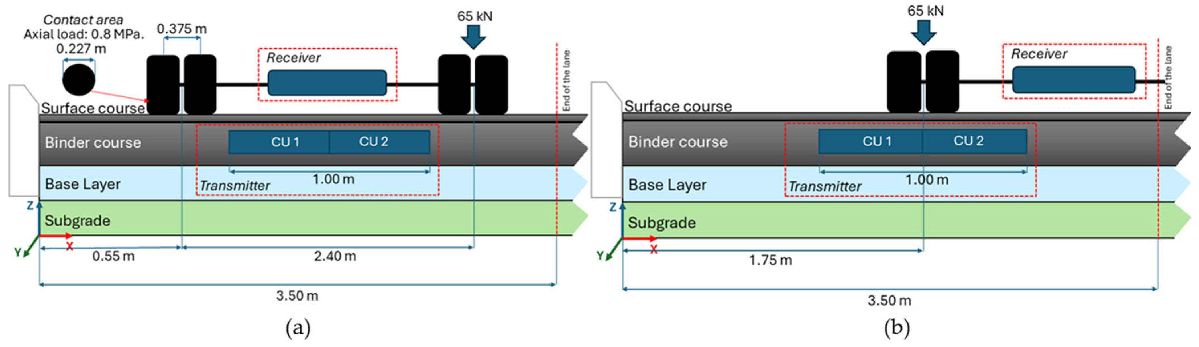
For the structural pavement analysis, the concept of equivalent single axle loads (N) was adopted, using a single axle with dual tires carrying a total load of 130 kN as a reference. The load was evenly distributed over four wheels, with a contact pressure of 0.8 MPa and a circular tire imprint diameter of 0.227 m.
Two loading configurations were evaluated. In the first scenario (
Figure 7a), the axle is positioned along the centerline of the charging lane, referred to as an “Aligned path”, representing the optimal alignment DWPT efficiency. In the second scenario (
Figure 7b), a lateral offset is introduced, referred to as a “Misaligned path,” in which one wheel partially overlaps the edge of a charging unit (CU). In both configurations, static vertical loads were applied.
In the finite element model, vertical pressure was applied to two circular plates (1 mm thick) placed directly on the pavement surface, representing the tire–pavement contact areas. These plates were not physical components of the pavement, but numerical tools to simulate the mechanical footprint of the tires. To replicate the load transfer behavior of pneumatic tires without modeling their geometry, the plates were defined with a Young’s modulus of 100 MPa and a Poisson’s ratio of 0.499, simulating a stiff yet nearly incompressible rubber-like interface. This approach enabled stable contact modeling and a realistic vertical stress distribution at the loading points.
The number of equivalent axle loads (
) was computed using the following equation:
where
r is the annual traffic growth rate, assumed to be 4%;
n is the design period in years. A 20-year lifespan was considered for semiflexible and semirigid pavements.
3.4. Mesh Description and Element Type
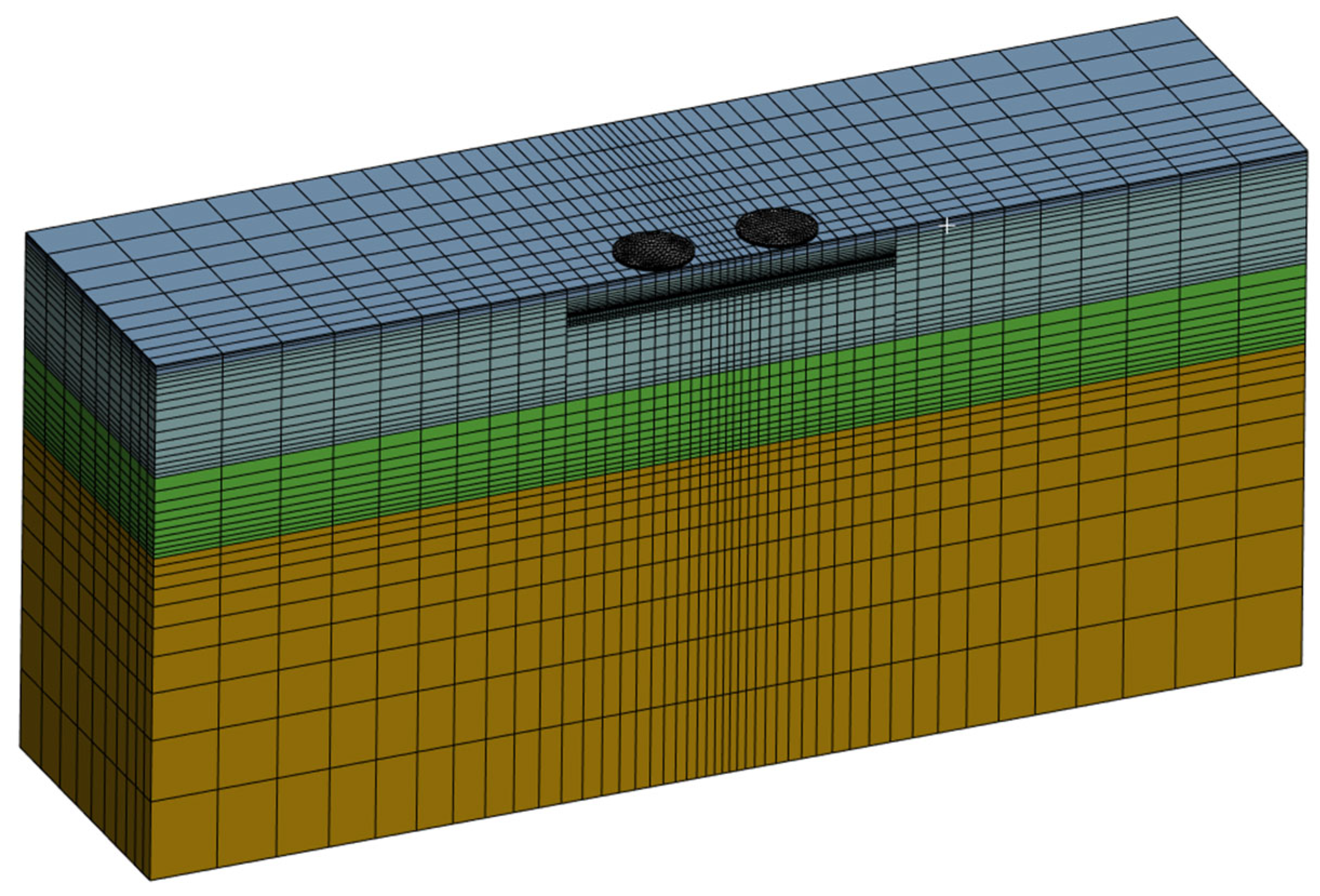
The three-dimensional model was discretized in ANSYS Workbench using a structured mesh composed of SOLID185 hexahedral elements, suitable for structural analysis in multilayer systems. A global element size of 100 mm was applied, with local mesh refinements down to 10 mm in critical interfaces, CU edges, and loaded areas. The domain was divided into three longitudinal zones (1a, 2, and 1b), allowing mesh density to be adjusted according to the load position. The models included between 30,000 and 58,000 nodes, and between 20,000 and 41,000 elements (
Figure 8). A sensitivity analysis confirmed mesh convergence, with variations of less than 5% between refinement levels.
3.5. Contact Type and Interface Configuration
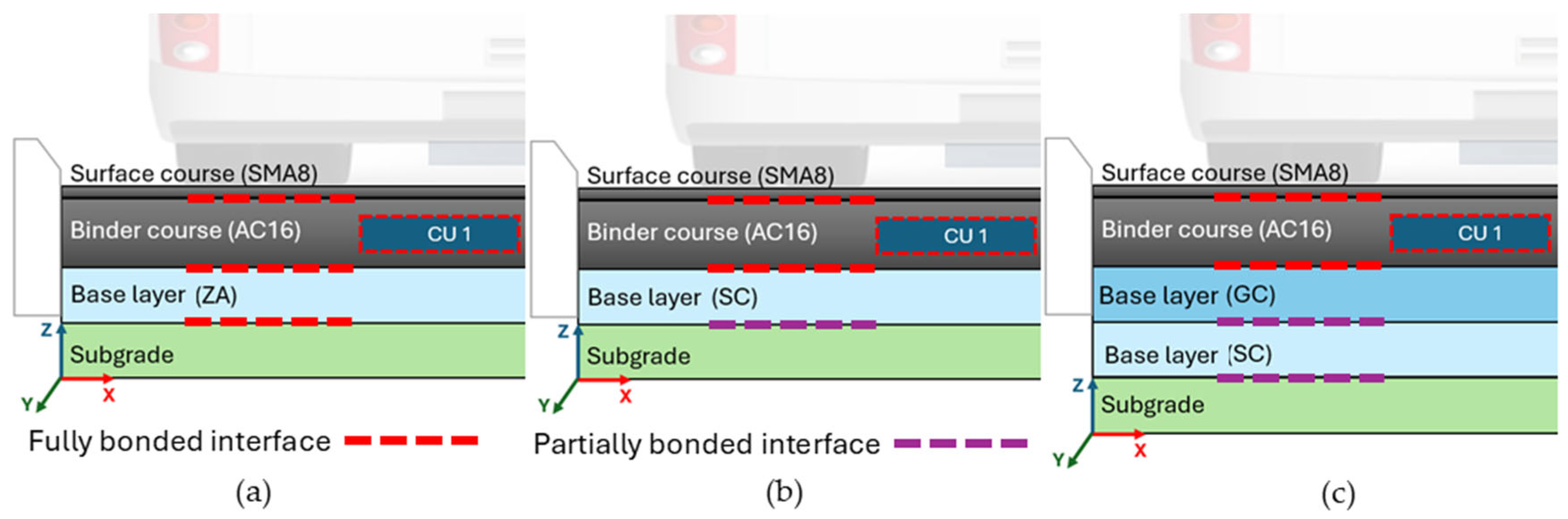
The interaction between pavement layers was modeled using linear and nonlinear contact conditions depending on the structural configuration. Full bonding was assumed between asphalt layers, between asphalt and granular bases, and between the bases and the subgrade, implemented in ANSYS using bonded contact elements. For interfaces involving cement-treated layers (soil–cement or gravel–cement), partial bonding was represented using a combination of Frictional and No Separation contact types, allowing limited sliding but preventing normal separation (
Figure 9). This differentiation enables a more realistic representation of stress transfer mechanisms within the multilayer pavement system.
The interface between the CU and the asphalt mixture was modeled as fully bonded, based on the experimental results by Boada et al. [
27], who applied a polyurethane resin adhesive (PRA) to PBT/PET-based CUs. With an application rate of 2500 g/m
2, a maximum shear bond stress (τ
SBT,max) greater than 0.8 MPa was achieved, exceeding the regulatory threshold, considered indicative of effective interlayer bonding in asphalt pavements [
28,
29]. Such values are commonly accepted in the literature to justify bonded contact conditions in FEM modeling of asphalt layers [
18,
21,
23], mainly when adhesive agents are used under controlled construction conditions. These considerations support the assumption of a bonded interface in this study.
3.6. Structural Distress Criteria and Pavement Service Life Prediction
Pavement durability is governed by the cumulative effects of damage caused by repeated loading, exceptional loads, and structural discontinuities. To estimate service life, Spanish Standard 6.1-IC provides specific fatigue laws for each pavement material, relating maximum stress or strain to the allowable number of load repetitions () before reaching the failure limit state.
In asphalt layers, the predominant distress mechanism is fatigue cracking, which is assessed using mechanistic–empirical models based on the strain (
) at the bottom of the asphalt mixture layers, as defined in the standard.
For granular materials and subgrades, damage is associated with the accumulation of permanent vertical strain, following the relationship below:
In the case of cement-treated layers, such as soil–cement (Equation (5)) or gravel–cement (Equation (6)), deterioration is modeled based on the tensile stress at the bottom of the treated layer, considering damage due to cracking, using the following expressions.
where
RF represents the flexural strength, assumed as 0.8 MPa for soil–cement and 1.3 MPa for gravel–cement.
Cumulative damage was evaluated using Miner’s Law, which quantifies deterioration under multiple applied loads:
where
is the number of equivalent axle loads expected over the design period, and
is the allowable number of repetitions before failure.
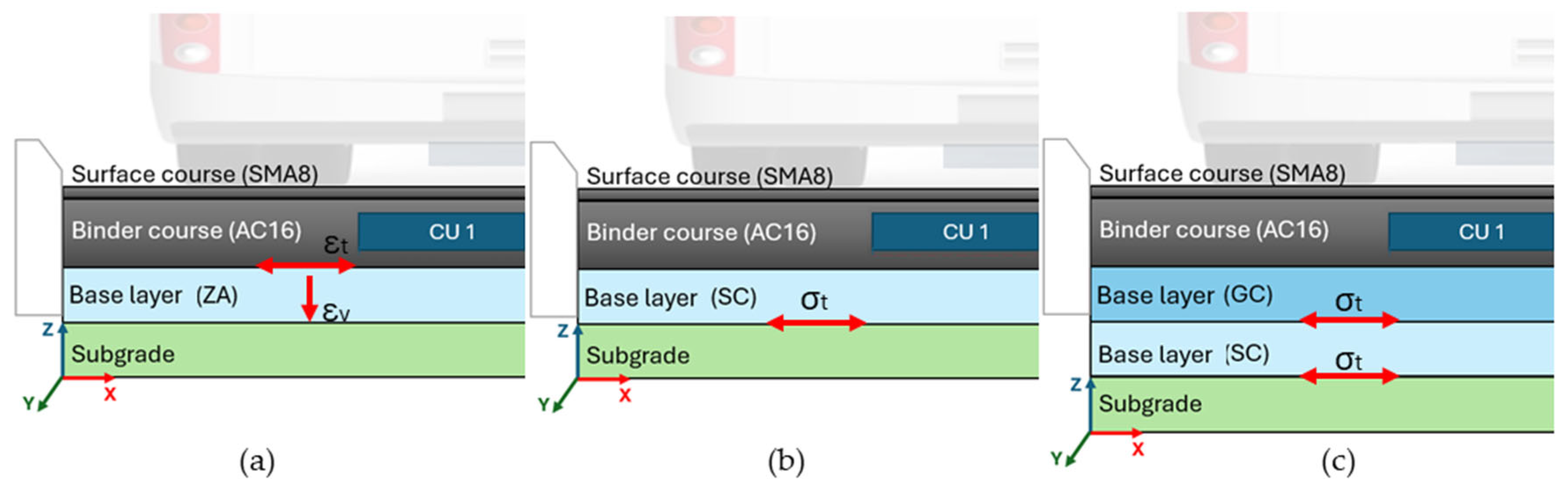
To identify zones of maximum structural demand, five control points (A, B, C, D, and E) were defined in areas where critical stresses or strains are typically concentrated (
Figure 10 and
Figure 11). In conventional elastic models, the location of these responses depends on both the load configuration and the pavement structure.
Points C and D, located in Zone 1a, correspond to the aligned path configuration, where the axle is positioned along the centerline of the charging lane. In this scenario, Point C lies between the dual wheels, while Point D is positioned directly beneath one of the wheels. Points A and B, located in Zone 2, represent the misaligned path, in which one wheel partially overlaps the edge of a CU; Point A is located between the tires, while Point B lies under the center of one wheel. Point E corresponds to the CU–asphalt interface, identified as critical in electrified pavements due to the localized stiffness discontinuity introduced by the embedded DWPT system. This interface was analyzed in both load configurations.
4. Results and Discussion
The structural response of the different pavement configurations was evaluated under static loading conditions corresponding to a dual-wheel axle, considering both centered (aligned) and offset (misaligned) loading scenarios relative to the Dynamic Wireless Power Transfer (DWPT) system. The results were analyzed in terms of key performance indicators: vertical displacements and deflections, internal mechanical responses, allowable load repetitions, and cumulative damage progression.
4.1. Vertical Displacements and Deflections
As an illustrative example,
Figure 12 shows the vertical displacement distributions for the semirigid section 0032 under T00 traffic conditions (see
Figure 3). This configuration typifies the general behavior observed across the 72 finite element models developed for the 18 pavement sections. When the load is applied near the curb, the reduced lateral confinement imposed by the boundary conditions leads to slightly higher displacements compared to those observed at the center of the lane. This outcome underscores the limitations of Boussinesq’s homogeneous half-space solution. It is consistent with Burmister’s multilayer elastic theory, which predicts increased surface deflections near pavement edges due to lower available lateral stiffness.
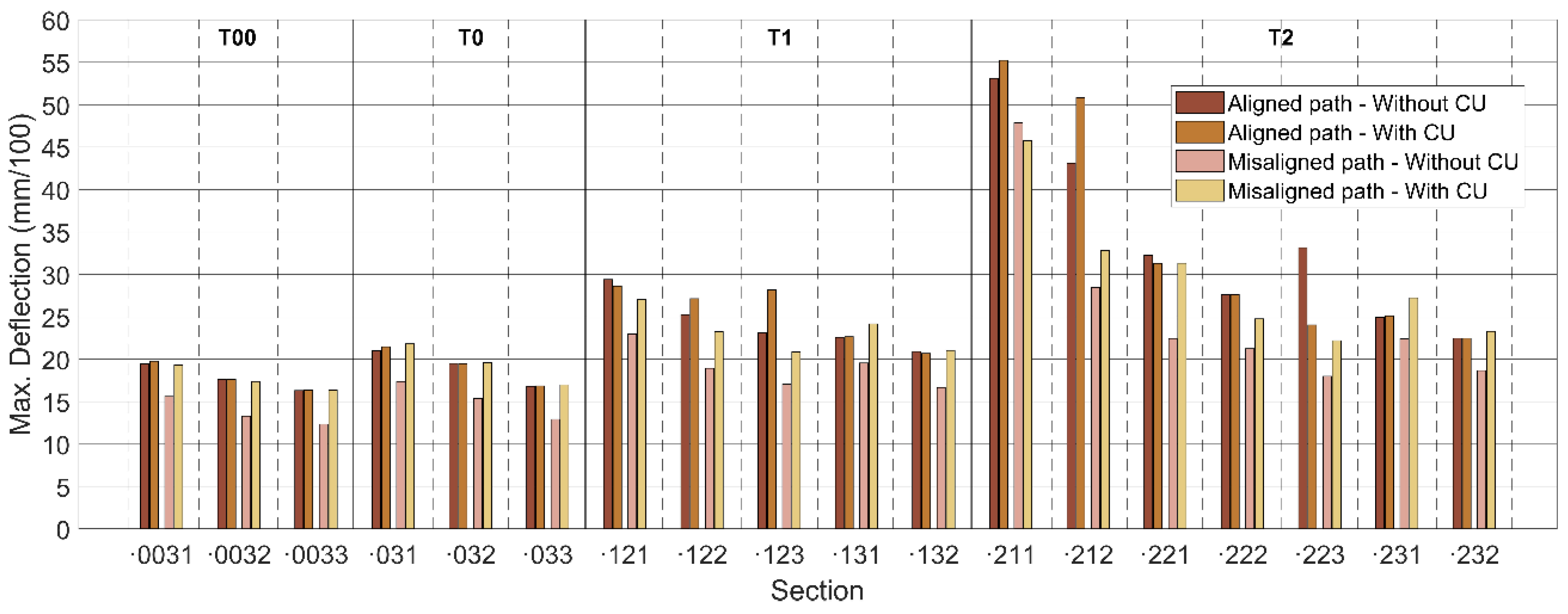
Figure 13 presents surface-level vertical deflections grouped by pavement type and loading configuration across the four scenarios. For the aligned path configuration, which includes the curb effect, average deflections increased by approximately 8% compared to non-electrified sections. In the misaligned path configuration, average deflections increased by about 14%, depending on the pavement section and loading condition. This effect was most pronounced in semiflexible pavements with a subgrade classified as E1, indicating greater structural sensitivity to localized stiffness discontinuities. For instance, in Section T221, misaligned loading resulted in a 28% increase in deflection, highlighting its vulnerability.
Semiflexible pavements exhibited the highest initial deflections, with an average increase of 10% upon incorporating the charging units (CUs), compared to both the same pavement type without CUs and the other structural typologies under equivalent traffic categories. In these sections, load alignment (centered or misaligned) had no substantial effect on the total surface deflection. In semirigid pavements with soil–cement (SC) layers, the higher base stiffness effectively reduced deflections; however, the inclusion of CUs led to an average increase of 9%, reaching up to 13% under misaligned conditions. Sections incorporating gravel–cement (GC) showed the lowest deflections overall. Yet, the addition of CUs resulted in an average surface deflection increase of 14%, with values reaching up to 20% when the load was misaligned. This suggests that CU integration has a significant effect on surface deformation, especially in flexible structures or when traffic paths are misaligned.
4.2. Internal Mechanical Responses
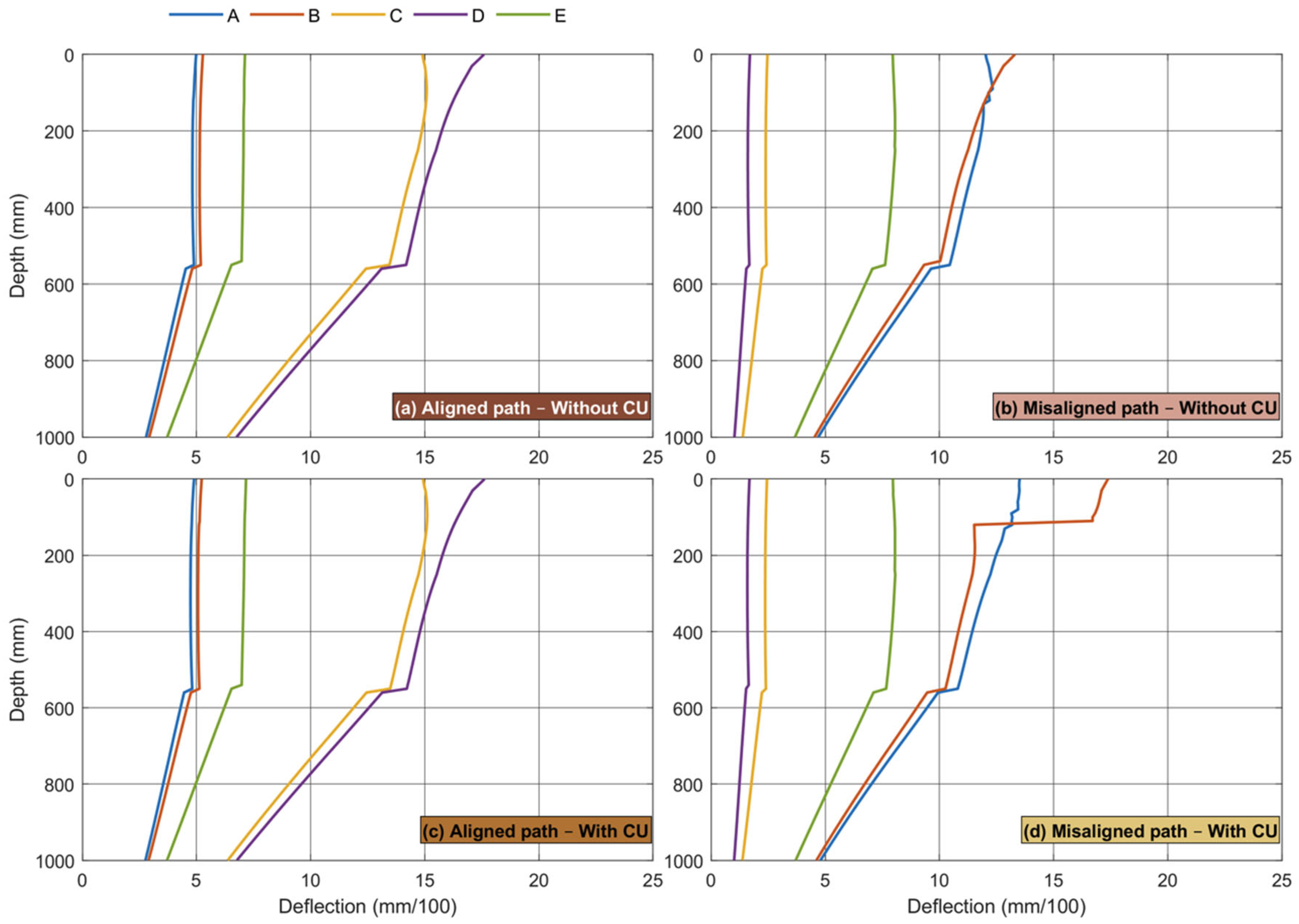
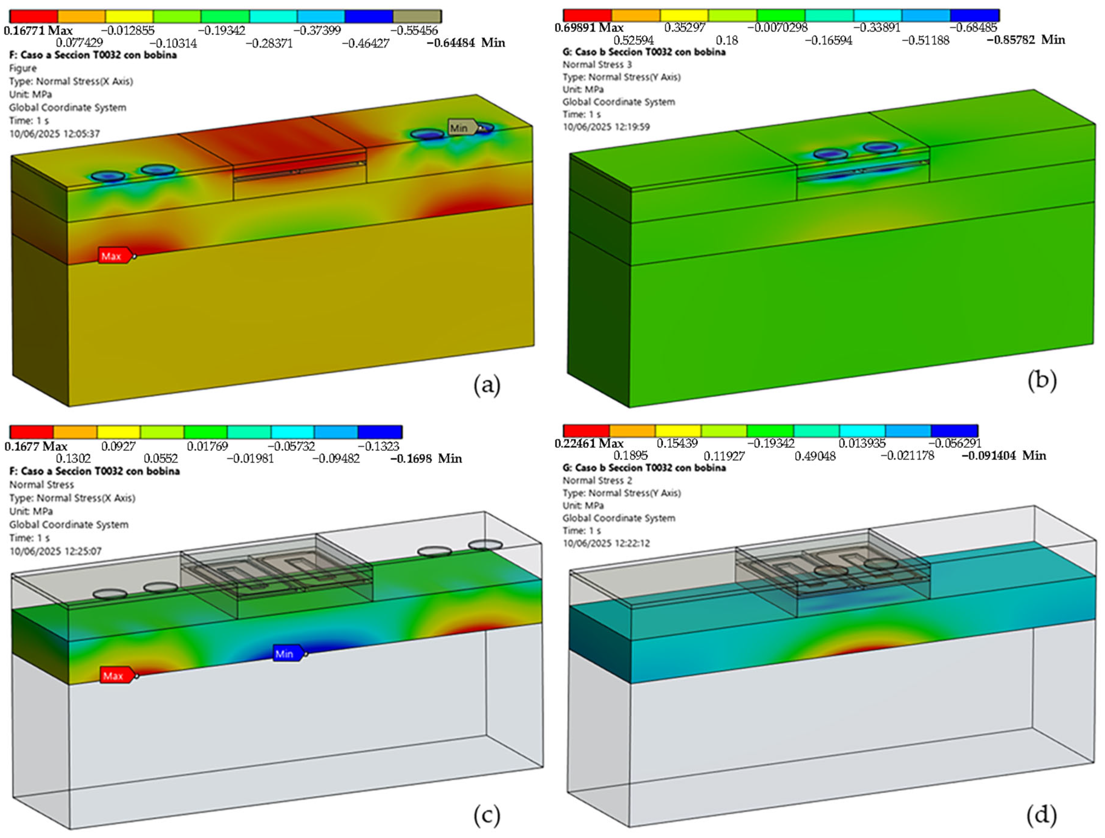
Internal stresses and strains were quantified to identify critical zones and anticipate structural failure modes. As an example,
Figure 14 displays representative strain distributions at critical points (A–E) in the semiflexible section T0031, while
Figure 15 illustrates peak stress values in the semirigid section T0032. This methodology was consistently applied to all 18 pavement sections, utilizing key-point analysis and 3D FEM results visualization. This approach enabled the extraction of maximum layer-specific values based on failure criteria, which were subsequently used for estimating service life.
The numerical models demonstrated consistent overall responses regarding maximum values, which is crucial for reliable analysis. However, minor discrepancies were observed in the precise spatial location of these peak values when comparing data extracted from the specific analyzed points (A–E) to the broader 3D visualization of the results. This slight positional shift, although not affecting the magnitude of the critical values themselves, underscores the importance of comprehensive spatial analysis in identifying the true localized maxima within the pavement structure. Therefore, relying solely on discrete control points may result in an underestimate of peak strain zones.
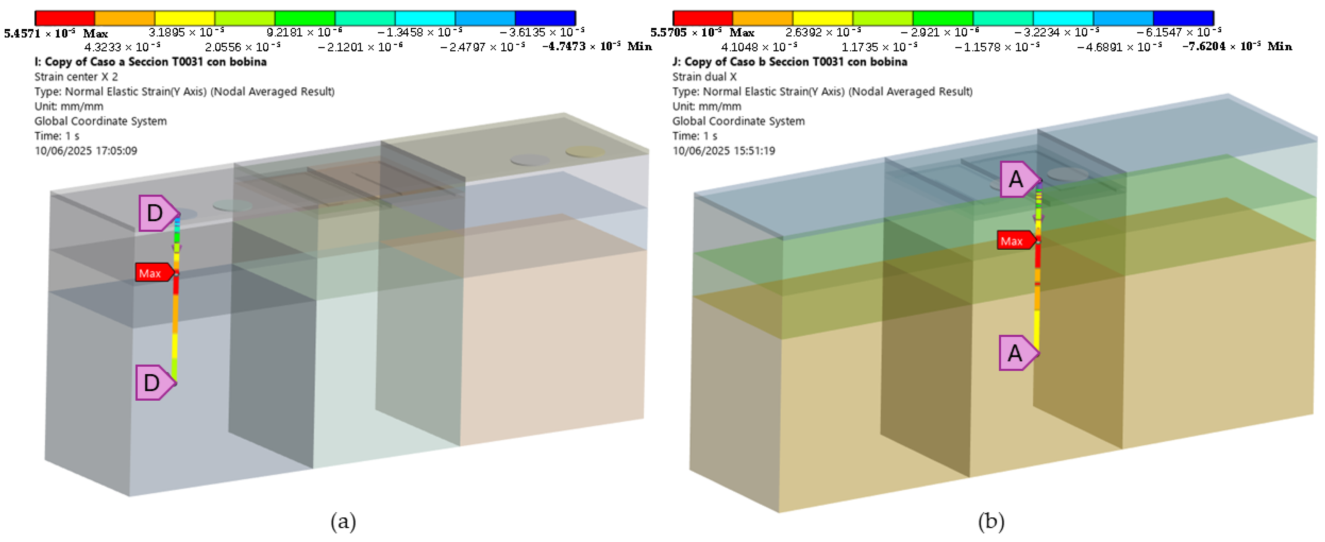
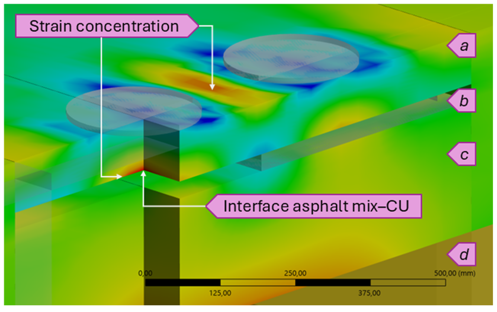
Among the structural parameters analyzed, the reduction in the upper binder layer (MB-BU) from 9 cm to 6 cm—required to embed the 3 cm thick charging unit (CU)—emerged as a key factor affecting near-surface mechanical performance. Although the total binder course (MB-B) thickness was preserved by increasing the lower binder layer (MB-BL), FEM simulations showed elevated tensile and tangential strain concentrations in the MB-BU and MB-S layers, particularly under misaligned loading when the tire overlapped the CU. These localized peaks, observed along the surface course and at the CU–asphalt interface (
Figure 16), increase the risk of microcracking and interfacial debonding, reducing pavement service life. Similar effects have been reported in other FEM studies, where thinner asphalt layers resulted in up to 2-fold increases in critical strains under comparable conditions [
30,
31,
32].
These strain concentrations, especially in the upper layers, underscore a key limitation of the current elastic multilayer modeling approach. While effective for comparative analysis, it does not capture time-dependent effects such as viscoelastic relaxation, plastic deformation, or thermal sensitivity, which are relevant in asphalt materials. A more comprehensive discussion of these limitations and the proposed shift toward viscoelastic and viscoplastic modeling is provided in
Section 4.4.
4.3. Allowable Load Repetitions and Cumulative Damage Progression
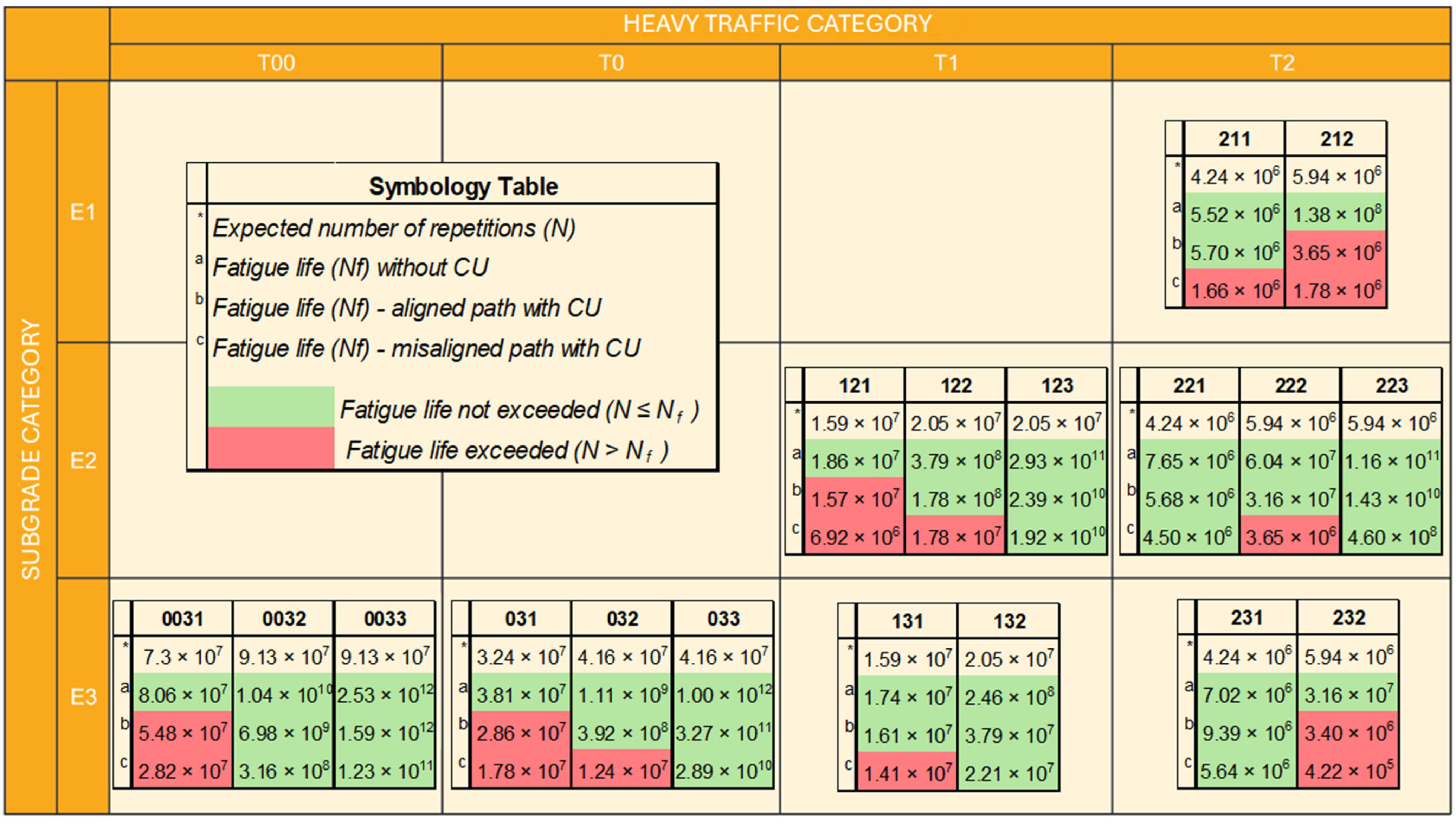
Structural durability was characterized by estimating the allowable number of load repetitions before failure (
) (
Figure 17), calculated using the fatigue laws defined by Spanish Standard 6.1-IC. The results indicated a reduction in the predicted service life for the electrified configurations, particularly under misaligned loading conditions, due to stress concentrations at the CU–asphalt mixture interface. On average, the
decreased by 60% in electrified designs compared to conventional ones.
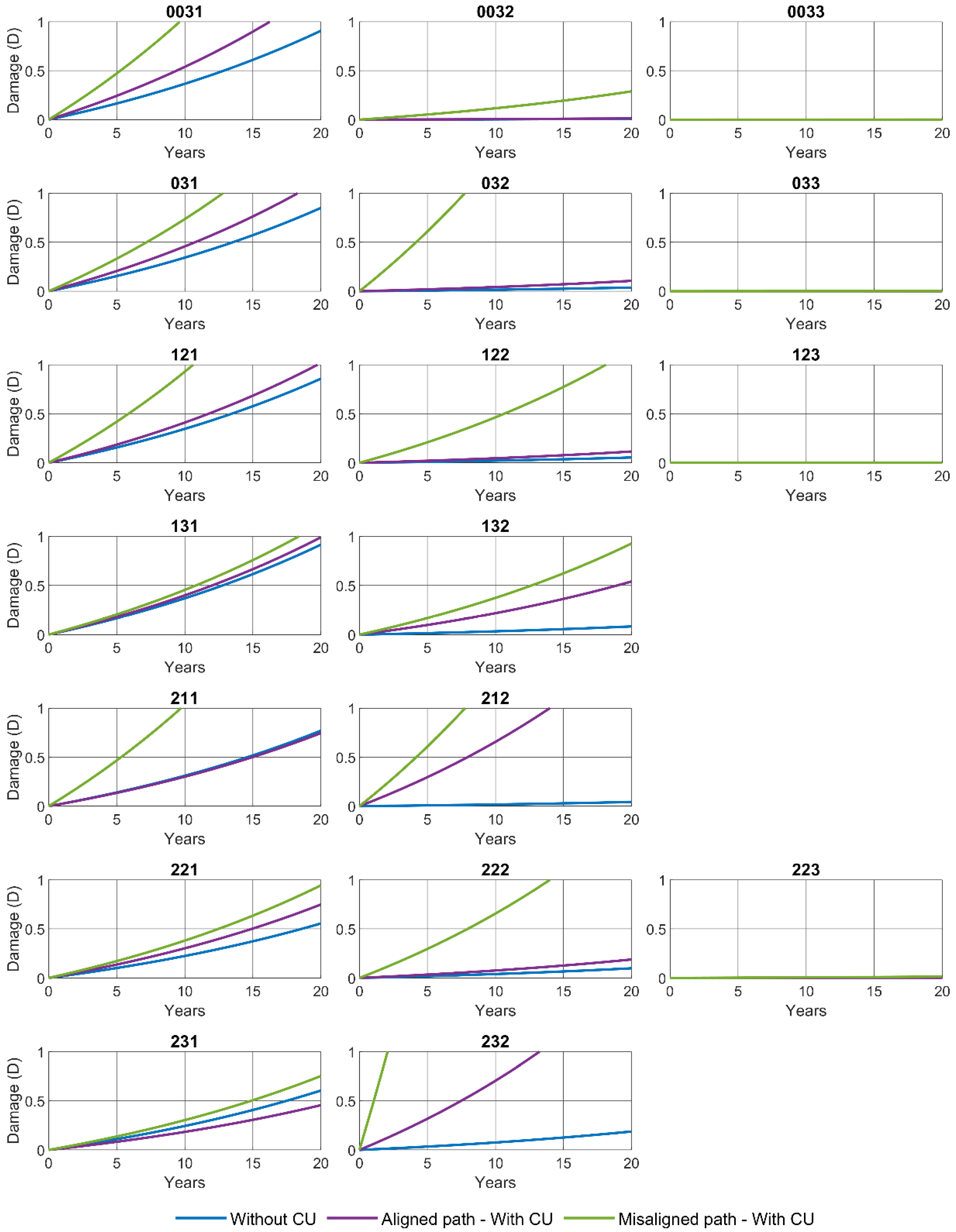
Figure 18 illustrates the progression of the structural damage index (D) for the 18 analyzed sections over a 20-year service period. The curves highlight notable differences in damage evolution between conventional pavements and those incorporating DWPT technology. In general, electrified pavements exhibit earlier damage initiation and a faster deterioration rate. This trend results in an average reduction of 24% in service life under aligned vehicle trajectories (i.e., with the CU positioned between the wheels), and up to 54% under misaligned paths, where the tire directly impacts the CU.
In semiflexible pavements subjected to traffic categories T00, T0, and T1, the average reduction in service life was 14% under aligned loading paths and 40% under misaligned paths. Sections 0031 and 031 failed to reach the 20-year design horizon in either scenario, suggesting that structural reinforcement is required to offset the impact of embedded CUs. For pavements designed for T2 traffic, the average reduction was approximately 15%, although most sections maintained service lives exceeding 20 years, except for section 211, which was affected by misaligned loading. This outcome suggests the potential need for segregated or dedicated charging lanes, designed to prevent vehicle wheels from directly contacting the embedded CUs. These findings can guide retrofit strategies for DWPT implementation in existing road networks.
Semirigid sections exhibited damage progression curves that remained relatively flat during the initial service period but became significantly steeper once more than 50% of the design life was consumed. This nonlinear behavior results from the high stiffness of cement-treated materials, which limits stress redistribution, and the logarithmic nature of the fatigue law, which causes fatigue life to drop sharply once stress thresholds are exceeded.
Although many sections still reached the 20-year service life, this apparent structural margin can be misleading: even minor variations—just a few centimeters—in the thickness of cement-treated layers may cause dramatic reductions in fatigue life, highlighting a high sensitivity to design parameters. For instance, sections 212 and 232 demonstrated an average fatigue life reduction of 54% under both aligned and misaligned loading conditions, indicating the need for additional structural reinforcement to accommodate DWPT systems safely. Conversely, other semirigid configurations may remain structurally viable with the implementation of segregated charging lanes, preventing direct tire loads over the embedded charging units (CUs).
Finally, semirigid sections combining gravel–cement (GC) and soil–cement (SC) layers exhibited the best structural performance, maintaining service lives exceeding 20 years, even under direct tire loading on the CUs. Their extremely flat damage curves suggest substantial structural overcapacity regardless of the loading path. Nonetheless, given the high fatigue sensitivity of cement-treated materials to small stress changes, even slight reductions in thickness or increases in loading could compromise long-term durability.
These results underline the heterogeneity of structural responses observed across all sections. While some configurations demonstrated acceptable performance, others were significantly affected by the integration of DWPT components. Therefore, their structural suitability depends not only on construction tolerances, but also—critically—on pavement type and material composition. These limitations and sensitivities are further addressed in
Section 4.4.
4.4. Limitations of the Simulation Approach and Future Improvements
While the simulation results quantify the structural response of electrified pavements, several limitations must be acknowledged. First, the analysis was conducted under linear elastic assumptions, following the Spanish Pavement Design Standard 6.1-IC. Although this enables standardized comparisons across configurations, it does not capture time-dependent effects such as viscoelastic relaxation or temperature-dependent stiffness. To address this, parallel studies are being conducted to characterize the viscoelastic behavior of SMA8 and AC16 asphalt mixtures at multiple temperatures. The resulting Prony series parameters will be implemented in future simulations to improve the prediction of stresses and strains under repeated loading.
Second, the interface between the charging unit (CU) housing and the asphalt mixture was modeled as fully bonded, based on laboratory adhesion tests using a polyurethane resin adhesive applied under controlled conditions. These tests yielded shear bond strengths above 0.8 MPa, exceeding the commonly accepted threshold of 0.6–0.8 MPa used in the literature to justify bonded contact assumptions in finite element models of asphalt layers. Nevertheless, interface bonding may weaken under in-service pavement conditions involving moisture, thermal cycling, and construction variability. While a fully bonded interface allows continuous stress transfer and monolithic mechanical behavior, partial bonding reduces interfacial stiffness and may lead to stress concentrations, delamination, or premature fatigue damage. To capture these effects, future models will incorporate cohesive contact laws calibrated from laboratory data, enabling simulation of both bonded and partially bonded scenarios.
Third, this study relies exclusively on numerical modeling. Although this allows systematic evaluation of pavement configurations, experimental validation remains essential. Falling Weight Deflectometer (FWD) tests are currently being performed on the CARDHIN pilot section, which replicates the electrified pavement structure simulated in this study. The measured deflection data will be used to calibrate the finite element models and assess their predictive accuracy under realistic traffic and environmental conditions.
Fourth, although the structural configurations and material properties were based on the Spanish Pavement Design Catalogue (6.1-IC), the modeling methodology—based on mechanistic–empirical multilayer theory and 3D finite element analysis—is adaptable to other national or international frameworks. By modifying input parameters such as traffic spectra, climate conditions, and material properties, the same approach can be applied under AASHTO (USA), Eurocodes (EU), or other regional standards.
Finally, the current analysis was performed using fixed input parameters, without evaluating the influence of variability in material stiffness, layer thickness, or interface condition. While this was necessary to ensure comparability between standardized pavement configurations, it limits the ability to assess the robustness of fatigue life predictions. A comprehensive sensitivity analysis is planned as a follow-up to this study, focusing on the most structurally critical configurations identified in this study. This will include parametric variation in mechanical properties, bonding conditions, and viscoelastic response, to assess model sensitivity and inform robust pavement design.
5. Conclusions
This study assessed the structural impact of integrating inductive charging units (CUs) into various pavement configurations representative of the Spanish road network, utilizing three-dimensional finite element modeling. While the results confirm the structural feasibility of DWPT systems, they also reveal localized alterations in mechanical response that can reduce pavement service life, particularly under misaligned loading. These effects are linked to geometric discontinuities, localized stiffness variations, and stress concentrations at the CU–asphalt interface. Ensuring proper layer compatibility and sufficient CU–asphalt bonding is essential to mitigate these effects.
In semiflexible pavements, maximum deflections remained essentially unchanged under centered loading. However, when the vehicle’s path coincided directly with the CU, localized increases in deflection and stress were observed in the upper 12 cm, while deeper layers exhibited a response similar to conventional sections. In contrast, tensile stresses and strains significantly increased near and beneath the CU, indicating a need for careful structural consideration. Therefore, it is strongly recommended to implement segregated charging lanes that ensure proper vehicle alignment and avoid tire loading directly over the CU, effectively mitigating overstress and extending pavement service life.
Semirigid sections, especially those with cement-treated layers (SC or GC), demonstrated high fatigue life even under critical loading conditions. The slow damage progression in these materials suggests potential overdesign, which could accommodate DWPT integration without additional reinforcement. Nonetheless, the fatigue behavior of cement-treated layers is highly sensitive to minor stress variations, underscoring the importance of precise thickness and load path control.
Although the elastic multilayer model used aligns with the Spanish design standard (Norma 6.1-IC), future studies should incorporate viscoelastic and nonlinear formulations, as well as thermomechanical coupling, to better reflect in-service conditions. These limitations and the proposed extensions are discussed in
Section 4.4.
The CU–asphalt interface emerged as structurally critical. While simulations with full bonding showed no significant discontinuities, experimental studies indicate that interface strength depends heavily on adhesive type and dosage. Although initial bonding was confirmed in lab tests using polyurethane adhesives, real-world performance may be affected by material adhesives, dosage, thermal cycles, and moisture. Nonlinear contact or cohesive zone models calibrated with experimental data are recommended to assess the risk of debonding and its structural implications.
Overall, these findings apply not only to the Spanish network but also to any road system with similar pavement typologies, supporting the efficient and durable integration of DWPT technologies in global transport infrastructure.
As part of future research, a comprehensive sensitivity analysis will be conducted to evaluate the influence of material stiffness, interface behavior, and pavement geometry on the structural performance of DWPT-integrated sections. This will help assess the robustness of design assumptions and identify critical variables for structural optimization.


 ,
, 


