Article

Mechanism of Friction Reduction in Surface Micro-Textured Mandrels During Hole Cold Expansion

1
School of Artificial Intelligence, Shenyang Aerospace University, Shenyang 110136, China
2
School of Mechanical and Electrical Engineering, Shenyang Aerospace University, Shenyang 110136, China
3
Yingkou Institute of Technology, College of Mechanical and Power Engineering, Yingkou 115014, China
4
Institute of Science and Technology, Shenyang Aerospace University, Shenyang 110136, China
*
Authors to whom correspondence should be addressed.
Coatings 2025, 15(7), 789; https://doi.org/10.3390/coatings15070789
Submission received: 10 June 2025 / Revised: 1 July 2025 / Accepted: 2 July 2025 / Published: 4 July 2025
(This article belongs to the Section Tribology)

Abstract

Aiming at the engineering problems of the severe wear and limited service life of mandrels during the hole extrusion strengthening of critical aerospace components, this study proposes a surface modification strategy for mandrels based on the anti-friction mechanism of micro-textures. Based on the Lame stress equation and the Mises yield criterion, a plastic strengthening stress distribution model of the hole wall was developed. Integrating Bowden’s adhesive friction theory, a parameterized numerical model was constructed to investigate the influence of micro-texture morphology on interfacial friction and wear behavior. An elastic–plastic contact model for micro-textured mandrels during hole extrusion strengthening was established using ANSYS. The effects of key parameters such as the micro-texture depth and area ratio on the contact pressure field, friction stress distribution, and strengthening performance were quantitatively analyzed. The results show that a circular micro-texture with a depth of 50 μm and an area ratio of 20% can reduce the fluctuation and peak value of the contact pressure by 41.0% and 29.7%, respectively, and decrease the average friction stress by 8.1%. The interfacial wear resistance and the uniformity of the residual compressive stress distribution on the hole wall are significantly enhanced, providing tribological insight and surface optimization guidance for improving the anti-wear performance and extending the service life of mandrels.

1. Introduction

As a key anti-fatigue manufacturing process of aviation equipment, hole extrusion strengthening technology constructs a gradient residual compressive stress field on the surface of the hole wall through controllable plastic deformation, which can significantly improve the fatigue life of components with holes by more than three times without changing the properties of matrix materials [1,2]. This technology has been widely used in aero-engine compressor blades, landing gear, and other components [3]. However, in the process of implementation, the mandrel, as the core force transfer medium, is in continuous contact with the hole wall under boundary lubrication conditions. The surface wear failure not only seriously restricts the service life of the mandrel but also causes the problem of the uneven distribution of the depth of the strengthening layer and the fluctuation of the processing quality [4]. How to achieve the optimal matching between the wear resistance and strengthening effect of the mandrel has become a key scientific problem to improve the stability and economy of the process.
According to the traditional tribological theory, reducing the surface roughness can effectively reduce the friction contact area, thereby improving the interfacial friction performance [5]. However, recent studies have shown that the construction of a micro-texture structure with a regular geometric morphology on the surface of the friction pair can reduce the friction coefficient, reduce the adhesive friction force, prevent gluing, and improve lubrication, thus significantly improving its tribological properties [6]. As a technology to actively regulate the interfacial friction performance, surface micro-texture has received extensive attention in recent years [7]. The mechanism is used to reduce the risk of interface wear by storing wear debris and lubricants and slowing down the concentration of shear stress [8]. Hamilton B et al. [9] revealed the anti-friction mechanism of a micro-convex structure under lubrication conditions for the first time, which laid the foundation for the micro-texture anti-friction theory. Subsequently, the academic community has carried out systematic research on the optimization of micro-texture parameters. Qin et al. [10] studied the friction properties of different shapes of pit textures on cobalt–chromium–molybdenum alloys and found that the circular pit texture has the most stable wettability and better wear resistance. Wang et al. [11] applied circular and triangular micro-textures to elliptical bearings and found that when the dimensionless texture depth is 0.03 and the radius is 3, the friction coefficient is the lowest and the lubrication effect is the best. Wan et al. [12] further confirmed that micro-texture can stabilize the friction coefficient, and the friction coefficient of the lubricated surface with micro-texture is 25% of that of the unlubricated surface. In terms of parameter optimization, Kitamura K’s [13] experiment proved that a 30% surface density of Φ20 μm micro-pits can reduce the friction coefficient of die steel from 0.75 to 0.4. The theoretical model of Tang et al. [14] pointed out that the texture with a diameter of 130 μm and an area ratio of 16.8% can reduce the friction coefficient of the slipper pair by 31.7%. Ji, J et al. [15] and Awasthi et al. [16] revealed the improvement mechanism of texture on the lubrication performance through simulations and experiments, respectively, emphasizing that it improves the bearing capacity by reconstructing the oil film pressure distribution; Andersson et al. used a laser to prepare the micro-texture on the surface of steel, which significantly reduced the friction coefficient and wear [17]; Zhang et al. [18] studied the improvement mechanism of rectangular micro-pits on the lubrication and wear performance of an electrostatic electric cylinder pump by laser processing. At present, micro-texture technology has achieved remarkable results in the fields of cutting tools [19,20], bearings [21], cylinders [22], and mechanical seals [23], but the application research in the hole extrusion strengthening mandrel is still missing. As the core component of load transfer, the interface friction behavior of the mandrel has a direct impact on the processing quality and efficiency. However, the existing research mainly focuses on the analysis of process parameters and residual stress and lacks a systematic exploration of the surface modification of the mandrel. The wear problem caused by the local stress concentration has been difficult to solve for a long time [24].
In view of the significant tribological benefits of micro-textures, this study proposes a surface modification strategy for mandrels used in hole extrusion strengthening, based on the anti-friction effect of surface micro-texturing. Through the fusion hole extrusion strengthening plasticity mechanics and interface tribology theory, the regulation mechanism of micro-texture on the stress distribution, friction behavior, and plastic deformation of the mandrel–hole wall interface was systematically revealed. The nonlinear contact three-dimensional elastic–plastic finite element simulation model of the micro-texture hole extrusion strengthening was carried out, and the influence of the texture morphology parameters on the interface contact pressure, friction stress, and strengthening performance was analyzed. The findings establish a surface-driven mechanism that balances interfacial friction optimization and extrusion strengthening, effectively addressing the durability limitations of conventional mandrels caused by severe friction and wear. This work offers a novel surface engineering approach for the precision anti-fatigue processing of critical aerospace components.

2. Extrusion Strengthening Friction and Wear Modeling Aanalysis

2.1. Hole Extrusion Strengthening Theory

The hole extrusion strengthening technology involves passing the mandrel through the inner hole of the holed component and expanding and squeezing the hole wall through its outer diameter to form a plastic deformation layer on the surface of the hole wall, thereby inducing residual compressive stress and generating high-density dislocations, inhibiting the fatigue crack initiation and effectively improving the fatigue life of the component [25]. In the analysis process, considering that the stiffness of the mandrel is much higher than that of the hole wall material, it can be simplified to only the elastic deformation, as shown in Figure 1.
When the mandrel squeezes the hole wall, the plastic deformation occurs first near the inner hole area, and the elastic deformation area is far away. The inner diameter of the hole wall model is 2 a , the outer diameter is 2 b , r represents the radial distance from the center of the hole, and σ r and σ θ represent the stress components along the radial and circumferential directions, respectively. The inner surface of the hole wall is subjected to uniform pressure P i , which is an incompressible ideal elastic–plastic body, ignoring the reverse yield behavior during unloading.
In the elastic stage, according to the Lame equation [26], the elastic stress distribution of the cylinder under the action of internal pressure P i is
{ σ r = p i a 2 b 2 a 2 ( 1 b 2 r 2 ) σ θ = p i a 2 b 2 a 2 ( 1 + b 2 r 2 )
when the internal pressure P i reaches the elastic limit load P e , the material begins to yield. According to the Mises criterion (plane strain, ν = 0.5 ), the equivalent stress σ e q satisfies:
σ e q = 1 2 [ ( σ r σ θ ) 2 + σ r 2 + σ θ 2 ] = σ s
where σ s is the yield strength of the material. Combined with the elastic stress formula, the elastic limit load P e is:
p e = σ s 2 ( 1 a 2 b 2 )
When the internal pressure is p i > p e , the cylinder enters the elastic–plastic state. Assuming that the elastic–plastic boundary radius is r s , according to the equilibrium differential equation, the stress in the plastic zone ( a r r s ) satisfies the equilibrium equation:
d σ r d r + σ r σ θ r = 0
Combined with the Mises criterion (under the plane strain condition σ θ σ r = 2 3 σ s ), the stress in the plastic zone is obtained by the integral
σ r = 2 σ s 3 ln ( r a ) σ θ = σ r + 2 σ s 3
the stress in the elastic region (   r s r b ) is
σ r = p r s 2 b 2 r s 2 ( 1 b 2 r 2 ) σ θ = p r s 2 b 2 r s 2 ( 1 + b 2 r 2 )
where P is the reaction pressure of the elastic zone to the plastic zone.
When unloading, it is regarded as reverse elastic deformation, and reverse pressure P i is applied. The elastic stress is
σ r = p i a 2 b 2 a 2 ( 1 b 2 r 2 ) σ θ = p i a 2 b 2 a 2 ( 1 + b 2 r 2 )
According to the principle of stress superposition, the residual stress after unloading is the superposition of the loading stress and the reverse elastic stress:
Δ σ r = σ r σ r Δ σ θ = σ θ σ θ
The depth δ of the strengthening layer is defined as the radial distance from the hole wall to the boundary of the plastic deformation zone:
δ = r s a
According to the relationship between the plastic boundary radius and the loading pressure, the elastic–plastic theory can be obtained:
r s = a p i p e
In engineering practice, when the outer diameter is significantly larger than the inner diameter, it can be considered that the constraint effect of the outer layer of the hole wall on the plastic deformation of the inner hole is significantly weakened, and the elastic limit load can be approximated as P e σ s . Combined with Formula (3), the expression of the depth of the strengthened layer is
δ = a p i σ s 1
The inner diameter is 2 a = 9.7   mm , the outer diameter is 2 b = 15   mm , the yield strength of the hole wall material is σ s = 480   MPa , and the contact pressure applied to the mandrel is P i = 1000   MPa . The above parameters are substituted into the analytical expression of the boundary position of the strengthening layer, and the depth of the corresponding strengthening layer is calculated to be δ 2.15   mm . The calculation results can provide a theoretical basis for the subsequent determination of the plastic deformation region.

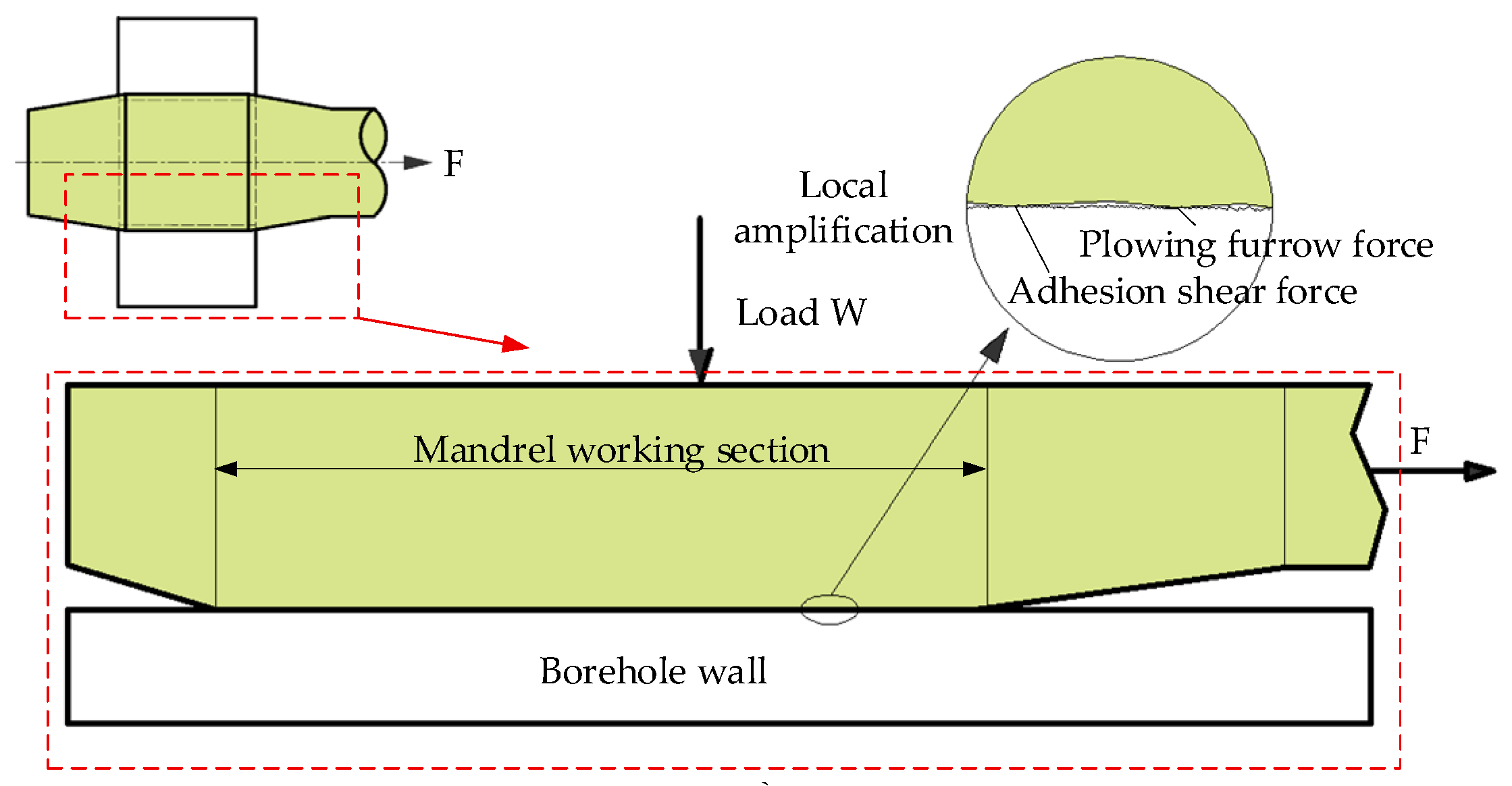
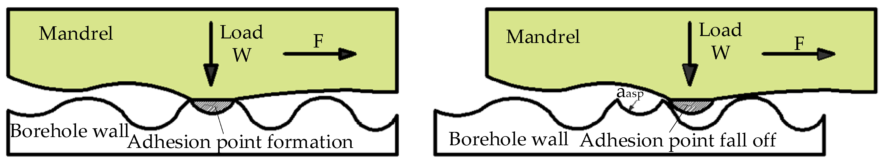
2.2. Non-Micro-Texture Extrusion Strengthening Friction and Wear Model

In aerospace hole cold expansion processes, while lubrication is commonly employed in industrial settings, this study adopts a dry sliding assumption to isolate and quantify the intrinsic effects of the micro-texture geometry on the interfacial friction behavior. This modeling choice ensures conservative predictions and facilitates a clearer understanding of the texture-induced contact modulation, without the confounding influence of lubricant film dynamics.
To systematically evaluate interfacial wear mechanisms, wear modes are categorized into four primary types according to tribological classification adhesive wear, abrasive wear, surface fatigue, and corrosive wear. Considering the dry contact conditions, elevated contact pressures, and the material pairing (i.e., a W18Cr4V mandrel and an aluminum alloy hole wall), this study focuses on adhesive and abrasive wear as the dominant mechanisms, while neglecting the surface fatigue and corrosion due to the relatively short contact duration and the absence of chemical or cyclic environmental loading.
Based on this, the theoretical modeling in this study is established on Bowden and Tabor’s adhesive friction theory [27], which attributes the interfacial friction behavior between the mandrel and the hole wall primarily to adhesive effects and plowing effects. Due to the existence of microscopic convex bodies on the surface of the material, the intermolecular force will cause a significant adhesive shear force during the relative motion. At the same time, the grooves formed by the high-hardness mandrel on the surface of the hole wall will also lead to an obvious plowing furrow effect, which together constitute the entire source of the friction.
As shown in Figure 2, the actual contact area between the mandrel and the hole wall is much smaller than the apparent area due to the significant surface roughness. During the loading process, the intermolecular force promotes the mutual adsorption of the asperities, thereby generating adhesion shear force. According to the theory of adhesive friction proposed by Bowden and Tabor, the friction force is mainly composed of the adhesive shear force F a and plowing furrow force F p . Among them, the adhesion shear force F a can be expressed as the product of the interfacial shear strength τ and the actual contact area A r . Considering that there is a certain proportional relationship between the actual contact area and the apparent contact area A a , it is usually expressed as A r = β A a (where β is the ratio of the actual contact peak surface to the apparent contact surface, 0 < β 1 ), then
F a = τ A r = τ β A a
Due to the high hardness of the mandrel material, grooves will be plowed out on the hole wall, resulting in additional friction. Assuming that the surface asperity is conical, and the furrow force is related to the contact pressure P , the material plowing furrow coefficient k p and the arithmetic average surface roughness h (i.e., h = R a ), then the plowing furrow force F p is
F p = k p h P
The total friction force can be expressed as
F 1 = F a + F p = τ β A a + k p h P
The normal load W is determined by the contact pressure P and the apparent contact area:
W = P A a
According to the above theoretical formula, the friction coefficient μ 1 can be derived:
μ 1 = F 1 W = τ β P + k p h A a
In addition to the friction force, the friction process will also cause the wear of the interface material. The adhesion–shear–shedding cycle at the microlevel, as well as the plastic extrusion and erosion caused by the plowing furrow effect, gradually accumulates and forms the wear volume of the macroscopic material. Especially under high stress contact conditions, such as hole extrusion strengthening, adhesive wear is the main failure mode. After the micro-protrusions on the surface of the material are removed, the undetected debris accumulates on the surface to form hard particles, which further aggravate wear and generate wear debris. For the friction pair between the mandrel and the hole wall, this paper uses the Archard model for the quantitative analysis [28].
As shown in Figure 3, according to the Archard model, the real contact of the interface mainly occurs between the surface micro-protrusions.
Assuming that the micro-protrusion is approximately a hemispherical protrusion, the radius is a p , the amount of adhesion–peeling in the unit time or unit slip distance is n p , and the peeling occurs when the slip distance reaches 2 a p under the action of the shear stress. The hemispherical wear volume is 2 / 3 π a 3 ,and the total wear volume in the unit sliding distance V 0 is
V 0 = ( 2 / 3 ) π a p 3 2 a p × n p = π a p 2 3 n p
Based on the above formula
V 0 = W 3 σ s
Assuming that K is the wear coefficient and the total slip length is L , the total wear volume V 1 is
V 1 = K W L 3 σ s = K W H L
Further considering that the friction pair material is an elastic material, and the yield strength is σ s = H / 3 , H is the Brinell hardness value, the apparent contact area A a is introduced, and the wear volume V can be converted to the wear depth Y 1 , and the expression is
Y 1 = V 1 A   a = K P L H
It can be seen from the above formula that under the condition of no micro-texture, the interface wear behavior is mainly affected by the micro-contact characteristics, loading conditions, and slip distance, and the contact area A a plays a key role in the model. When the actual contact area is small, the local contact compressive stress increases significantly, which can easily cause severe plastic shear and micro-protrusion shedding, resulting in a rapid increase in the wear volume.
After the introduction of the micro-texture structure, the real contact area and stress distribution of the interface change, which affects the macroscopic parameters, such as the wear volume W , friction force F , and friction coefficient μ . In order to accurately reveal the anti-friction mechanism under the micro-texture, it is necessary to compare and analyze the interface physical change process caused by the texture based on the non-texture model and further construct the friction and wear theoretical model and behavior evolution mechanism under micro-texture conditions.

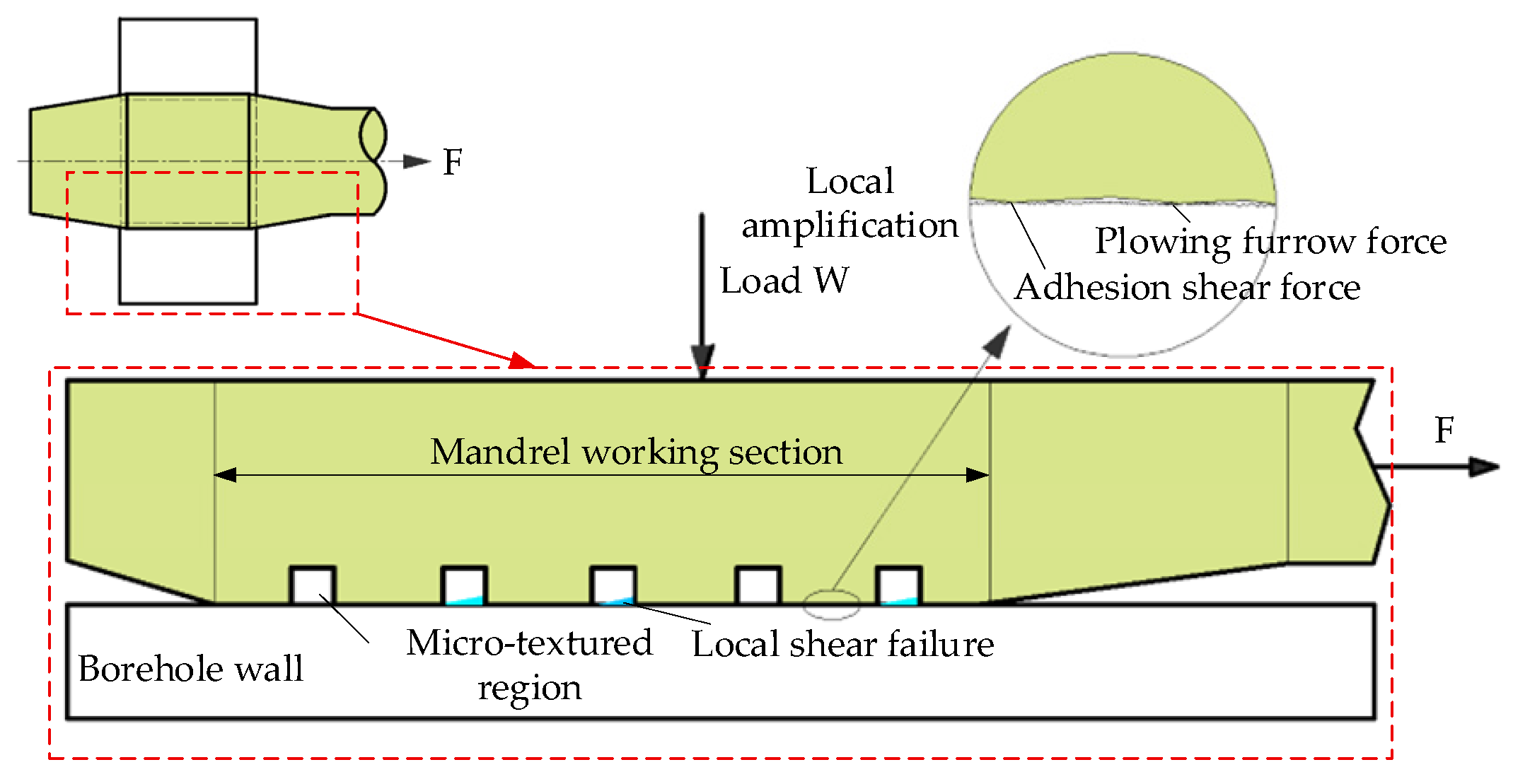
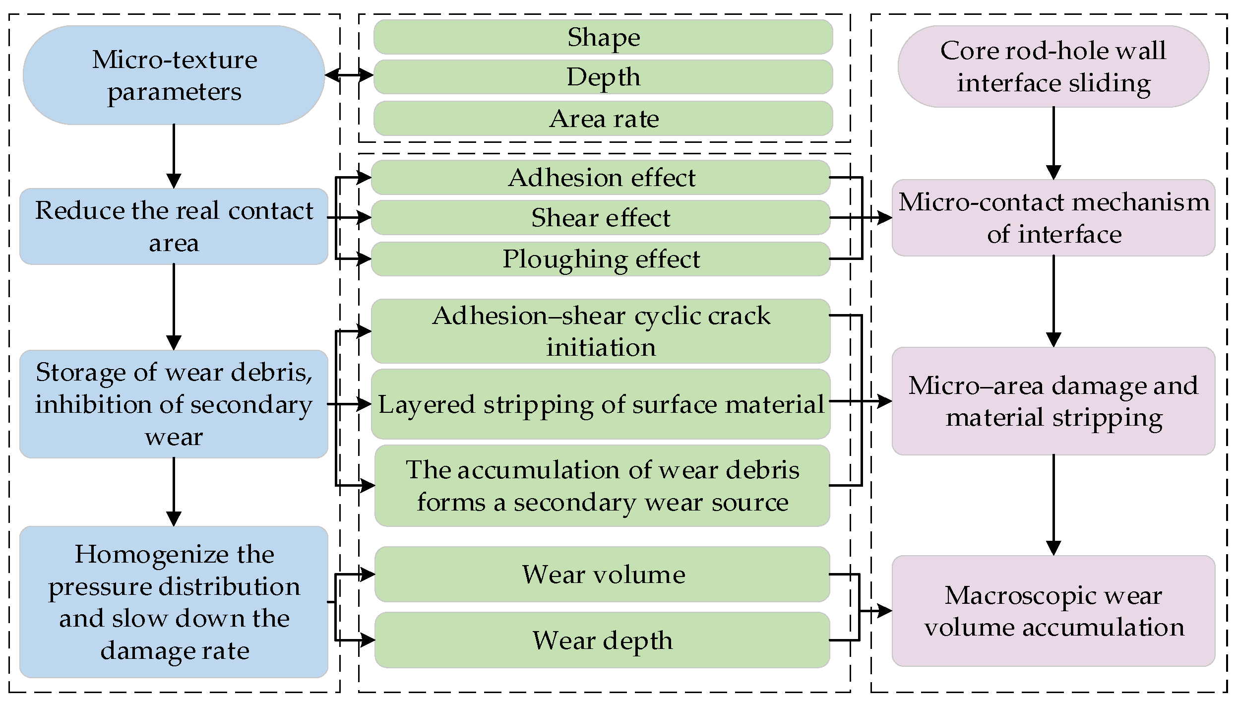
2.3. Micro-Texture Extrusion Strengthening Friction and Wear Model

In order to further improve the service stability and wear resistance of the hole extrusion strengthening mandrel, the surface micro-texture technology is introduced in this paper, and the theoretical model of the interface friction and wear under the condition of the micro-texture is constructed, and its mechanism in regulating the contact mechanical behavior is systematically analyzed.
As shown in Figure 4, the micro-texture can effectively regulate the distribution of the real contact area of the interface by constructing a pit with a specific geometric morphology on the surface of the mandrel. At the same time, it has the functions of lubricant storage, wear debris accommodation, and stress release and plays a significant anti-friction role in the friction pair. On the premise of not changing the overall load, the micro-texture realizes the reconstruction of the friction path, thereby improving the anti-friction performance of the mandrel.
In terms of theoretical modeling, this paper takes the circular micro-texture of the regular array as the representative and constructs a friction model with an area rate and depth parameter correction. The existence of the micro-texture reduces the actual contact area of the interface, so that the non-texture area bears a higher unit load, thereby changing the local adhesion behavior. The adhesion shear force F a in this region can be expressed as
F a = τ β A a ( 1 η t )
where η t is the area ratio of the micro-texture.
In the analysis of the plowing force, the change in texture depth h t also has a significant effect on the friction behavior. In the analysis of the plowing furrow force, the change in the texture depth h t also has a significant effect on the friction behavior. On the one hand, the existence of the depth is more conducive to the storage of lubricants and the effective isolation of shear layers, thereby reducing the direct contact between surface rough bodies; on the other hand, if the depth is too large, the edge of the pit easily forms a stress concentration zone, which may cause local plastic collapse and weaken the anti-friction effect of the micro-texture [29]. Therefore, the texture depth correction coefficient α is introduced in this paper to characterize its influence on the plowing furrow force. The plowing furrow force F p is expressed as
F p = k p h P ( 1 α h t h r )
where h r is the reference depth.
The stress concentration at the edge of the micro-texture will cause local shear failure, which is related to the total area of the texture unit and the local shear strength τ l . The local shear failure force F s is
F s = η t A a τ l
The total friction force can be expressed as
F 2 = F a + F p + F s
When there is a micro-texture, the micro-texture affects the wear behavior by changing the contact area and local stress distribution. The effective contact area is reduced, and the normal load W 1 is
W 1 = P A a ( 1 η t )
According to the above theoretical formula, the friction coefficient μ 2 can be derived:
μ 2 = τ β A a ( 1 η t ) + k p h P ( 1 α h t / h r ) + η t A a τ l ( 1 η t ) P A a
In addition to the influence on the friction coefficient, the micro-texture also plays a key role in slowing down the wear of materials. In the process of interface sliding, the existence of the texture can break the continuous sliding path of the material at the macrolevel, accommodate the wear debris at the microlevel, and slow down the heat accumulation and local stress accumulation, thus reducing the erosion rate of the microarea of the interface material.
Based on the modified expression of the Archard model, the wear volume V 2 under the condition of the micro-texture is
V 2 = K W L H = K P A a ( 1 η   t ) H
The micro-textured wear depth Y 2 is
Y 2 = V 2 A a = K P L ( 1 η t ) 2 H
The results of the upper model show that the reasonable design of micro-texture parameters can significantly reduce the wear rate per unit area, thereby prolonging the service life of the mandrel. In the process of the hole extrusion, the contact pressure between the mandrel and the hole wall is often higher than the yield strength of the aluminum alloy, and the contact pressure is usually in the high-pressure range of more than 1000   MPa in practical application. The typical pressure value P = 1000   MPa is selected as the representative working condition to carry out the modeling and parameter optimization analysis [30].
The key parameters used in the model were selected based on representative values commonly reported in tribological studies. Specifically, the material shear strength ( τ = 400   MPa ) and local shear strength ( τ l = 500   MPa ) correspond to typical values for hardened W18Cr4V steel under cold working conditions. The surface roughness height was set to 0.3 μm, representing a finely polished mandrel surface that reflects typical machining and finishing conditions for cold-working dies. The contact area ratio ( β = 0.05 ) was estimated from the Hertzian contact theory, and the material plowing furrow coefficient ( k p = 0.2 ) was selected from the typical range (0.1–0.3) reported for metallic surfaces with near-Gaussian roughness profiles under dry sliding conditions [31]. A depth correction factor ( α = 0.5 ) and a reference depth ( h r = 50   μ m ) were adopted to account for nonlinear asperity penetration effects. These values ensure physical consistency and facilitate comparative modeling. The influence trend diagram of different micro-texture parameters on the friction coefficient μ 2 is drawn for Formula 26, as shown in Figure 5.
From Figure 5, it can be observed that under high contact pressure, the friction coefficient increases with the increase in the texture area rate and the decrease in the depth, and the effective contact area adjustment caused by the change in the area rate is larger, showing a more sensitive response. The theoretical analysis shows that a smaller area ratio and a larger depth are helpful in reducing the friction coefficient and improving the anti-friction performance. However, in the actual texture manufacturing process, too small an area ratio may lead to an insufficient texture distribution, and it is difficult to form an effective disturbance zone. An excessive depth can easily cause a stress concentration at the edge of the pit, resulting in structural instability. It can be seen that the micro-texture design under high-pressure conditions needs to control the geometric parameters strictly, and the theoretical model can provide a basis for the reasonable selection of the parameter interval.
In summary, the micro-texture can effectively intervene in the friction and wear evolution of the mandrel–hole wall interface by regulating the real contact area, redistributing the shear load, storing the lubricant, and accommodating the wear debris. At the microlevel, the micro-texture realizes the multi-level linkage regulation of the stress distribution adjustment, heat accumulation inhibition, and wear path reconstruction. In order to intuitively show its influence on the contact behavior and damage evolution, the flow chart of the micro-texture regulation on the friction–wear mechanism shown in Figure 6 is constructed.

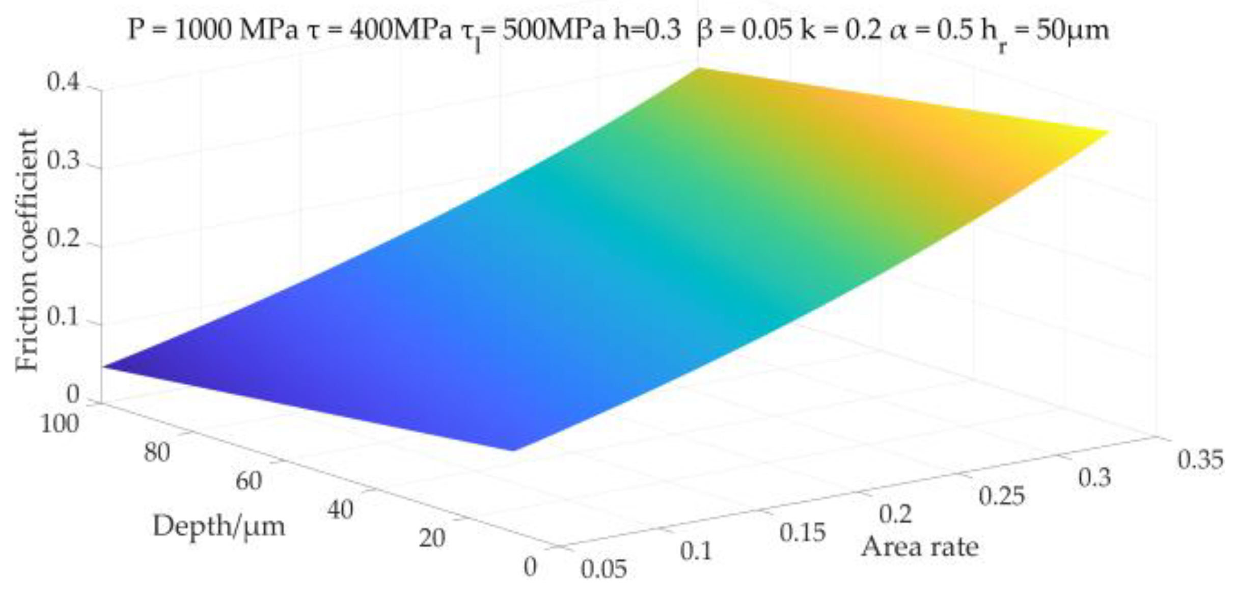
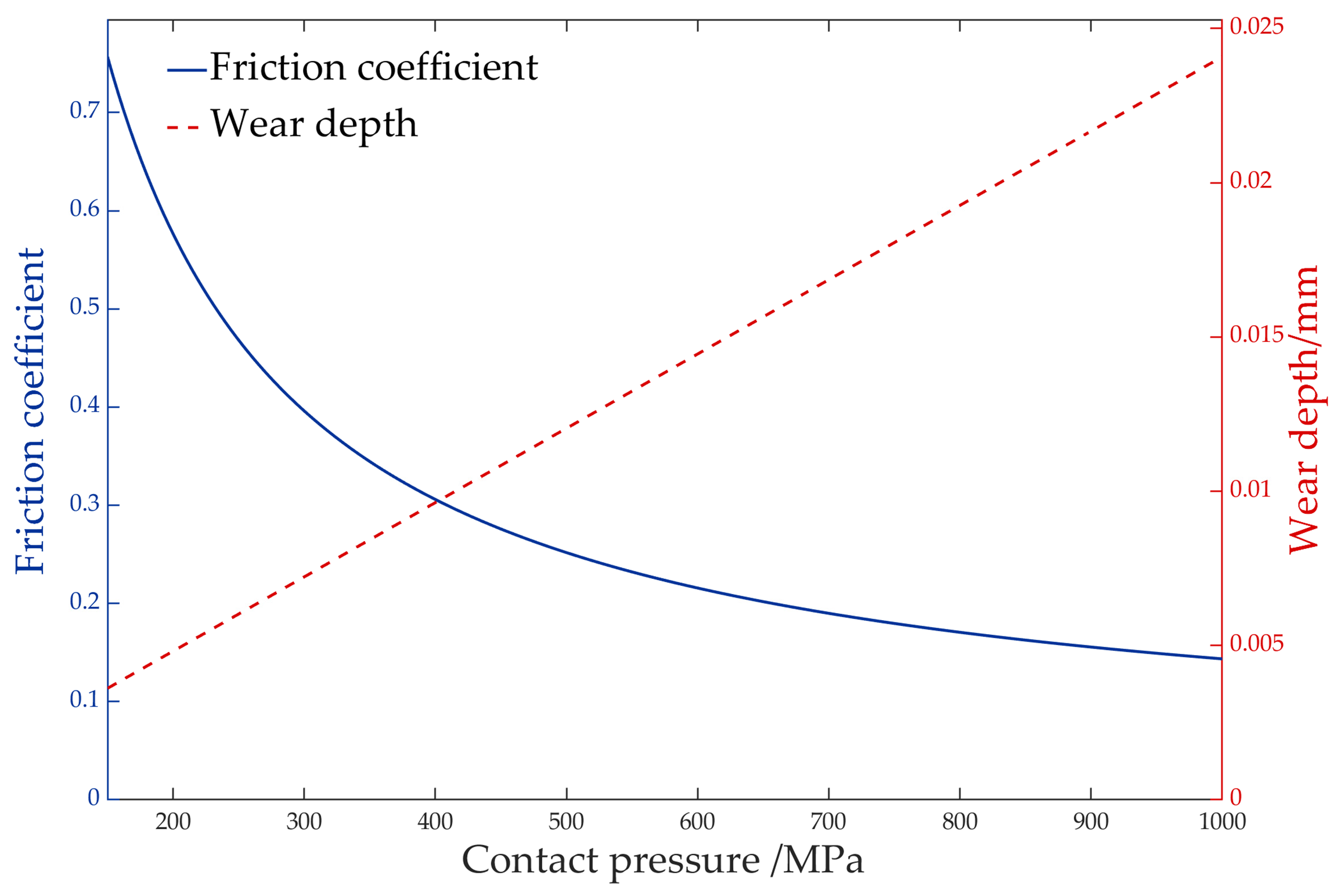
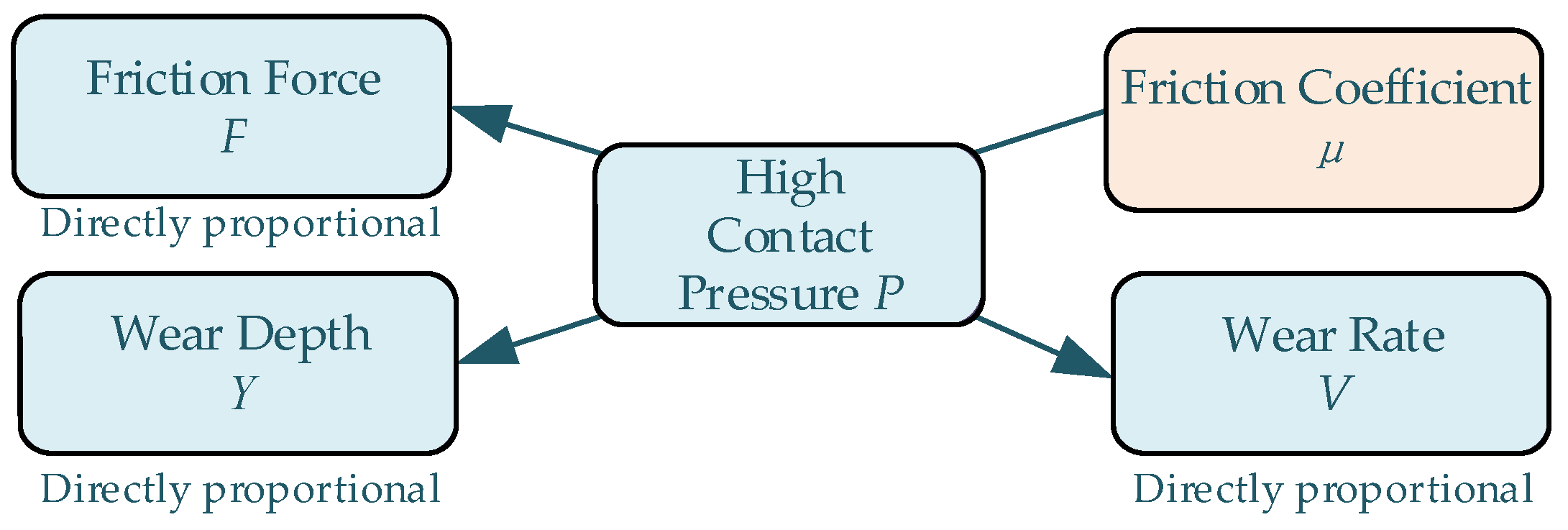
2.4. The Coupling Effect Mechanism of Contact Pressure on Friction and Wear

The contact pressure P is the core variable that controls the friction behavior of the interface and the evolution of the material wear during the hole extrusion process. It determines the normal load distribution of the interface and is a key parameter to evaluate the anti-friction effect of the micro-texture. Although the friction coefficient μ is often used as a macroscopic index of the interface friction state, its change trend has a nonlinear relationship with the actual contact conditions, and it is difficult to fully describe the interface friction mechanism.
During the extrusion process, the height of the contact pressure field formed by the mandrel propulsion is uneven, especially in the working section, where the local pressure peak easily occurs. By introducing geometric perturbation structures, such as pits, micro-textures can realize the stress redistribution, reduce the maximum contact pressure, and make the interface load distribution more uniform [32]. If the texture morphology design is unreasonable, the contact stress concentration area is easily formed at the edge of the pit, which may induce local shear instability and boundary material damage, thereby reducing the stability and wear resistance of the friction interface. In order to reveal the coupling relationship between the contact pressure P , friction coefficient μ , and wear depth Y , the three-dimensional response surface of Formulas (25) and (27) is drawn as shown in Figure 7.
The results show that with the increase in the contact pressure, the friction coefficient shows obvious nonlinear decreasing characteristics: in the low pressure region ( P < 400 ), the variation range is larger, and in the high-pressure region, it gradually tends to the platform state. This trend is consistent with the results reported by Kim et al. [33]. Although the friction coefficient is often used to characterize the interfacial friction state, its value tends to stabilize under high-pressure conditions, making it less sensitive in capturing the regulation effect of micro-textures on frictional behavior.
Since the above trends are derived from a specific material system, it is important to further clarify the applicability and limitations of the proposed model. Notably, the P–μ–Y response surface presented in this study is based on a typical hard–soft contact pair, specifically involving a micro-textured W18Cr4V steel mandrel and a 7050 aluminum alloy hole wall. For such material combinations, the micro-texture design plays a critical role in redistributing the contact pressure and improving the wear resistance. While the current model provides practical guidance for hard–soft systems commonly used in hole cold expansion processes, its extension to other material pairings—such as soft–soft or hard–hard contacts—may involve different deformation and wear mechanisms. In these cases, model parameters may need to be appropriately adjusted or supported by an additional experimental or numerical calibration to ensure a broader applicability.
Differently from the friction coefficient, the wear volume V and depth Y increase linearly with P , indicating that even if μ tends to be stable, the wear behavior is still mainly controlled by the normal load, and the wear rate continues to rise. This trend has been verified in the experiment of a micro-textured Ti6Al4V alloy [34]. Accordingly, this paper constructs the coupling evolution flow chart of the contact pressure–friction–friction coefficient–wear behavior shown in Figure 8, so as to systematically sort out the internal relationship of each variable under the guidance of the contact pressure.
In summary, the key to the micro-texture anti-friction mechanism is to accurately control the contact pressure distribution to achieve a peak reduction, load diffusion, and stress homogenization, rather than simply reducing the value of the friction coefficient. Especially under high-pressure conditions, a reasonable texture design can effectively alleviate the stress concentration, enhance the wear resistance of the mandrel, and improve the uniformity of the strengthening layer. Based on the above theory, the influence of micro-texture parameters (shape, area ratio, and depth) on the maximum contact pressure, pressure standard deviation, and load uniformity of the interface will be systematically analyzed with the pressure distribution uniformity as the optimization goal, and the synergistic anti-friction and anti-wear mechanism will be further clarified.

3. Mandrel Structure Design Based on Micro-Texture

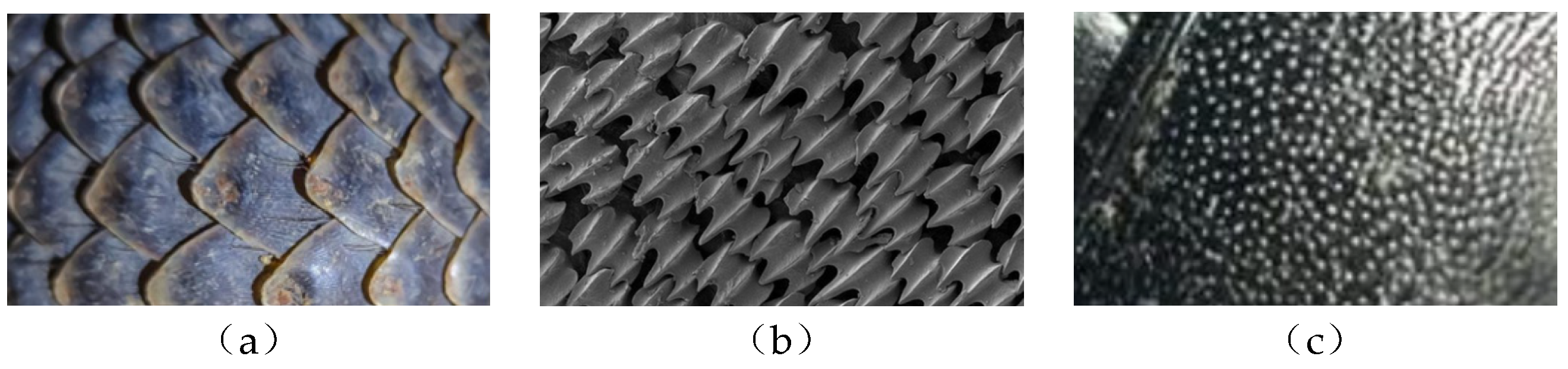
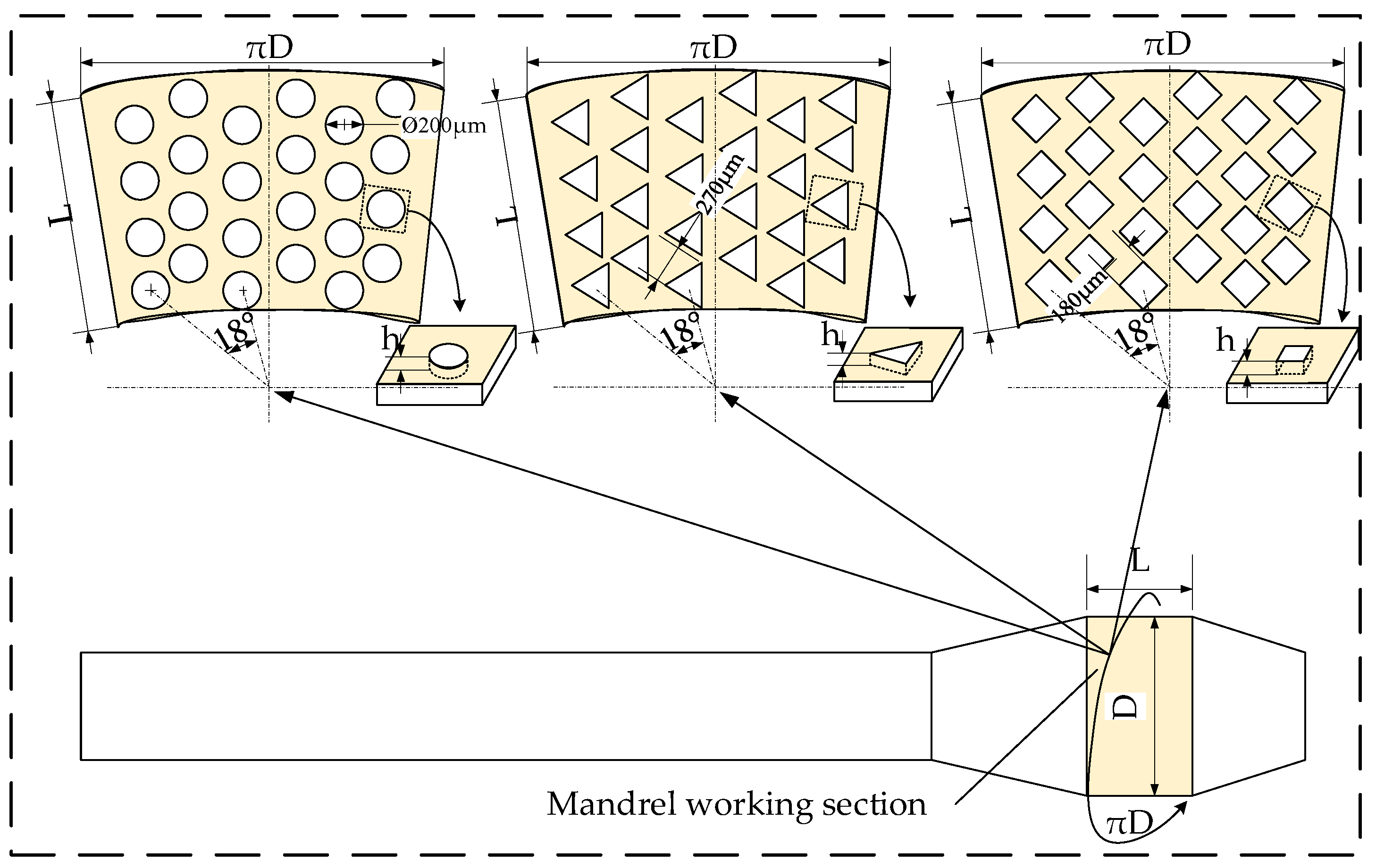
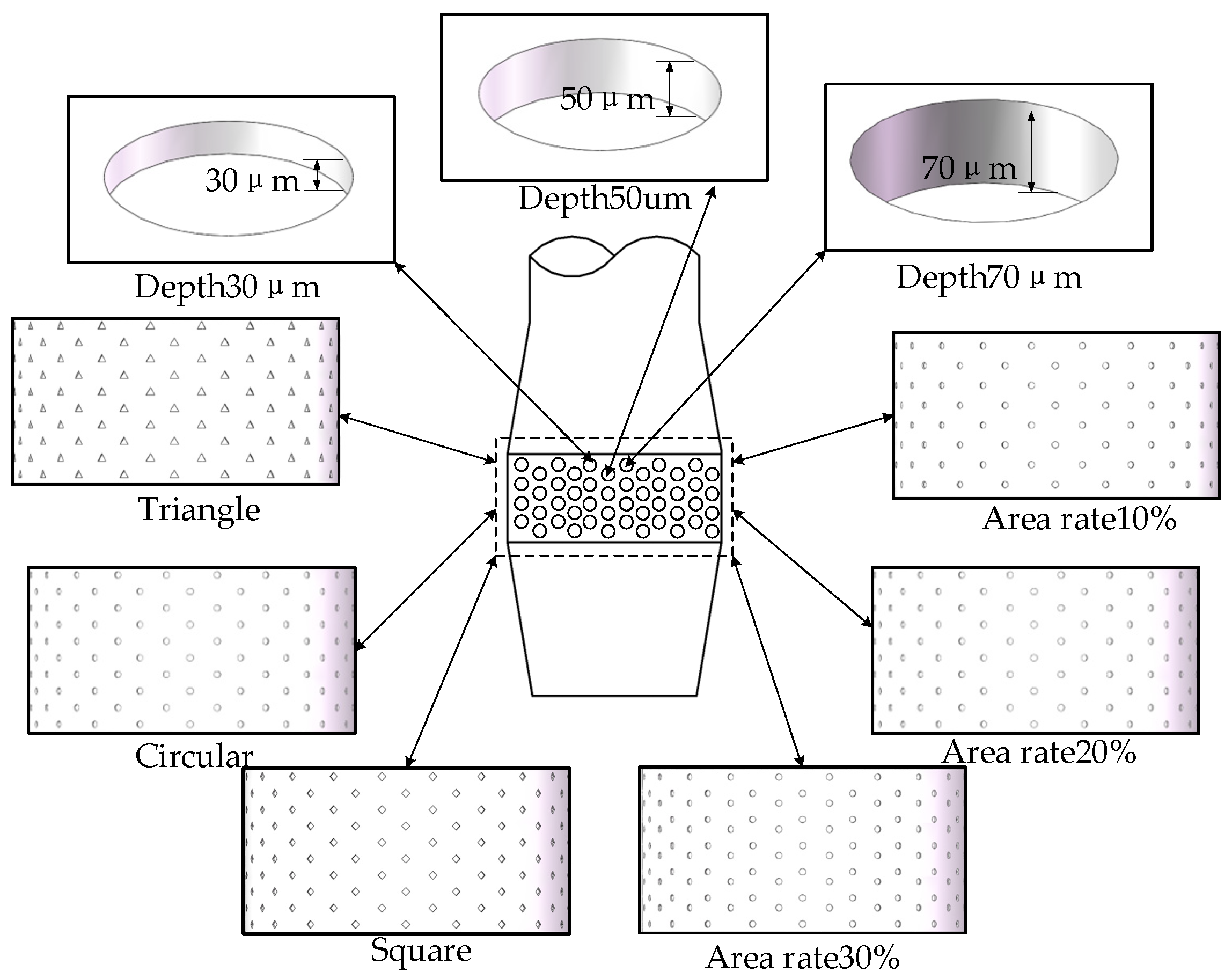
3.1. Micro-Texture Structure Design

The micro-texture parameters directly affect the anti-friction performance and determine the lubrication storage, wear debris discharge capacity, and interface load distribution uniformity. In order to balance the friction reduction and load-bearing, the design needs to strike a balance between tribology and material mechanics. Studies have shown that if the structure size or density is improper, it is easy to cause a stress concentration and increase the fatigue damage and wear rate [35].
Therefore, the design of microstructures needs to start from the perspective of multi-physical field coupling and comprehensively consider the synergistic effect of the lubrication field, the mechanical field, and the interfacial energy field. In recent years, biomimetic design has become an important path, and by borrowing the micromorphology of natural wear-resistant structures, the evolutionary advantages can be extracted and transformed into processable engineered micro-texture configurations.
As shown in Figure 9, the observation of the typical biological surface structure shows that the grooves of pangolin scales can guide the discharge of wear debris, the arrow-like texture of shark skin can induce fluid dynamic pressure to reduce shear resistance, and the pit array of the dung beetle shell achieves a uniform load distribution through a fractal layout. These characteristics provide important enlightenment for micro-texture design. Bionic morphology can break through the traditional geometric constraints and realize the active control of the friction performance.
Based on the principle of bionics, this paper constructs a multi-dimensional micro-texture parameter system, as shown in Figure 10, covering key factors such as the shape, depth, and area ratio. The micro-texture shape adopts a regular geometric array. The area ratio represents the proportion of the total area of the pit to the surface area of the mandrel working area. The depth h is the vertical distance from the surface to the bottom of the pit. The arrangement method uses the bionic feature to select the network-like distribution to optimize the load distribution uniformity.
In order to realize the quantitative control of micro-texture parameters, this paper accurately defines and calculates each structural feature quantity. N is defined as the number of micro-pits, S c is the area of a single texture, and S 1 is the area of the working surface of the mandrel. Since the working area is a cylindrical surface, the surface area S 1 is calculated by the formula S 1 = π D L , where D = 10   mm and L = 5   mm are substituted into S 1 = 157   mm 2 .
The diameter of a single circular pit is Φ = 200   μ m , and the area is S c = π r 2 = 0.0314   mm 2 . The square and triangular pits are adjusted by adjusting the side length to make their area equal to the circular pit, corresponding to the side lengths of a = 180   μ m and a = 270   μ m , respectively. The ratio of the sum of the area of all micro-pits to the area of the rectangular surface is the micro-pit area occupancy S , then there are
S = N S C S 1
Combined with the theoretical analysis, too low an area ratio will lead to a sparse distribution of texture, and it is difficult to form an effective disturbance layer, which limits the lubrication and load regulation functions. Too high an area ratio may weaken the surface continuity and increase the risk of an interference between microstructures. The texture depth is also critical; too shallow a depth and it is difficult to accommodate the wear debris and oil storage, and too deep a depth easily causes an edge stress concentration, resulting in local plastic collapse. Therefore, this paper sets three typical area ratios, 10%, 20%, and 30%, and three typical texture depths, 30 μm, 50 μm, and 70 μm, and comprehensively evaluates their wear resistance and mechanical stability under different working conditions. In summary, the final micro-texture parameter design is shown in Figure 11.

3.2. Establishment of Micro-Texture Simulation Model

The finite element model of micro-textured mandrel hole extrusion strengthening mainly includes the micro-textured extrusion mandrel and the hole extrusion sample plate. The diameter of the working section of the mandrel is 10 mm, the length is 5 mm, the front cone section and the rear cone section are 10 mm and 8 mm, respectively, and the front and rear cone angles are 3.5° and 9°, which conforms to the design criterion of the hole extrusion mandrel. The size of the sample is 30 mm×30 mm×10 mm. The diameter of the initial hole is set according to the relative extrusion amount, and the diameter of the hole after the extrusion is 9.7 mm. The hole extrusion assembly model is shown in Figure 12.
In this paper, the experimental material is the AL-7050 high-strength aluminum alloy, the material of the hole extrusion strengthening mandrel is W18Cr4V steel, and the stiffness is hole extrusion mandrel greater than hole extrusion sample. The main material properties are shown in Table 1.
The material constitutive model is constructed based on the elastoplastic theory to describe the mechanical behavior of the mandrel and the hole wall during the hole extrusion strengthening process. For the AL-7050 aluminum alloy and W18Cr4V steel, the Von Mises yield criterion is used to determine whether the material enters the plastic stage:
F = 1 2 [ ( σ 1 σ 2 ) 2 + ( σ 2 σ 3 ) 2 + ( σ 3 σ 1 ) 2 ] σ s = 0
among them, σ 1 , σ 2 , and σ 3 are the main stresses, and σ s is the current yield stress. The total strain increment d ε i j is decomposed into the elastic part d ε i j e and the plastic part d ε i j p , namely
F = d ε i j = d ε i j e + d ε i j p
The elastic strain increment follows the generalized Hooke’s law:
d ε i j e = 1 + v E d σ i j v E d σ k k δ i j
in the formula, E is the elastic modulus, σ i j is the stress increment tensor component, d σ k k is the first invariant of the stress tensor, and δ i j is the Kronecker unit matrix.
The plastic strain increment is described by the Prandtl–Reuss flow rule:
d ε i j P = d λ F σ i j
In the formula, d λ is a plastic multiplier, which must satisfy the consistency condition F = 0 . The evolution of the yield stress of the material with the equivalent plastic strain ε ¯ p is characterized by
σ s = σ 0 + K s ( ε ¯ p ) n
where σ 0 is the initial yield stress, K s is the strength coefficient, and n is the strain hardening index. The accumulation of the equivalent plastic strain is calculated by the following formula:
d ε ¯ P = 2 3 d ε i j P : d ε i j P
Considering the complex geometric characteristics of the micro-textured mandrel, especially the irregular shape of the surface pits, the mandrel is meshed by the tetrahedral element SOLID187, which has a good geometric adaptability. For the regular hole template, the hexahedral element SOLID185 is used for division. Considering the large stress gradient in the micro-texture pit area, the local mesh refinement technology is used to ensure the mesh quality of the pit edge and the hole wall contact area, so as to improve the calculation accuracy.
In terms of the contact setting, the mandrel working face and the hole wall adopt a surface–surface friction contact. Considering that the friction coefficient tends to be a platform in the high-pressure region, its change has little effect on the friction reduction effect. To improve the convergence of the simulation, this paper selects μ = 0.12 [37], which is located in the stable interval predicted by the theoretical model. This effectively eliminates the variable interference and highlights the regulation effect of micro-texture parameters on the contact stress.
The Newton–Raphson iterative algorithm of ANSYS (2021R2) is used in the solution process. The algorithm decomposes the external load into several sub-steps, and multiple balanced iterations are performed in each sub-step. By calculating the current stiffness matrix and internal force, it is judged whether the convergence criterion is satisfied. If it does not converge, the iterative calculation is continued until the convergence condition is satisfied. This method has a good computational efficiency and stability. The contact algorithm uses the augmented Lagrangian method, which can effectively deal with complex contact nonlinear problems. When the contact is detected, the contact force is determined by the combination of the penalty function and the Lagrange multiplier, which not only ensures the calculation accuracy but also avoids excessive constraints. The finite element model is shown in Figure 13.
The hole extrusion strengthening process is divided into three stages: The first stage is the extrusion stage, and the mandrel begins to make contact with the hole wall and gradually causes plastic deformation. In this stage, a stable contact relationship between the mandrel and the hole wall is established by applying an axial displacement load. The second stage is the strengthening stage, which continues to push the mandrel so that the working section is in full contact with the hole wall to achieve plastic strengthening. This stage is the key period for the hole wall material to produce a stable plastic flow and form a strengthening layer, and it is also the most complex stage of the interface friction behavior. Its mechanical response directly determines the performance of the mandrel and the strengthening effect of the hole wall. The third stage is the unloading stage, and the displacement load is removed, the system enters the elastic recovery process, and the hole extrusion strengthening is completed. The simulation process of each stage is shown in Figure 14.

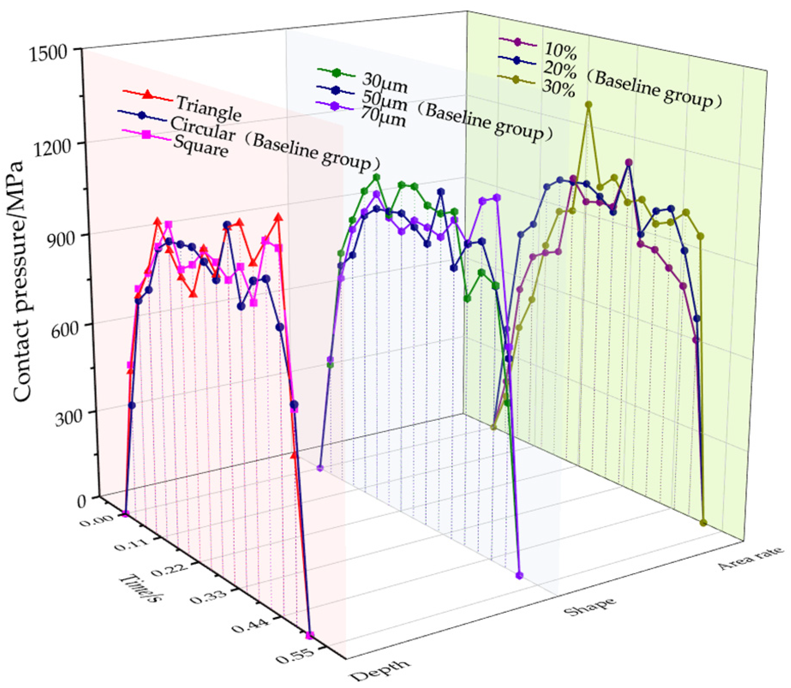
3.3. Parameter Analysis of Micro-Texture Structure

In order to clarify the influence of different micro-texture geometric parameters on the contact mechanical behavior of the mandrel–hole wall interface, based on the three-dimensional finite element model, hole extrusion simulations are carried out around the three key variables of the shape, area ratio, and depth. Under the premise of consistent material properties, contact settings, and loading conditions, according to the theoretical analysis, a representative parameter combination—a circular texture, 50 μm depth, and 20% area ratio—is selected as the baseline group (G1). All simulations use the single-factor method to adjust the texture parameters one by one and analyze their effect on the regulation of the contact pressure distribution by varying micro-texture parameters, as shown in Table 2.
Considering that the micro-texture mainly acts on the working section of the mandrel, the result analysis focuses on the contact pressure cloud diagram and the path evolution curve of the region to reveal the influence of the local texture disturbance on the mechanical properties of the overall interface. Figure 15 and Figure 16 show the contact pressure distribution cloud diagram under different micro-texture parameters and the contact pressure curve extracted at the same time.
As shown in Figure 15, the contact pressure cloud charts under different micro-texture parameters distinctly reveal variations in the interfacial contact behavior. In the analysis of shape parameters, the circular texture in the baseline group exhibits a uniformly distributed contact pressure field without observable concentration zones, indicating stable load transfer characteristics. In contrast, the square texture generates a concentrated high-pressure contact region near the extrusion inlet, which is likely attributed to the local shear accumulation induced by its geometric sharp corners. The triangle texture exhibits multiple discontinuous high-pressure contact zones located centrally along the working section, suggesting a susceptibility to interrupted load paths and a potential interfacial instability.
In the analysis of the texture depth, based on the circular shape and a 20% area ratio, the 30 μm depth produces the highest overall contact pressure, as shown by the darker regions in the pressure maps. However, a distinct region of reduced contact pressure appears near the center of the working section, reflecting local non-uniformities in the pressure distribution. At a depth of 70 μm, although the overall pressure level is reduced, a similar low-pressure zone re-emerges, indicating a compromised contact consistency and limited capacity to sustain uniform interface loading.
Regarding the area ratio, both 20% (baseline group) and 30% configurations yield relatively uniform contact pressure fields, implying that this parameter range facilitates more the effective regulation of the load transmission and the suppression of localized pressure peaks. By contrast, a 10% area ratio leads to an insufficient pressure redistribution due to excessive spacing between textures, thereby weakening the friction-reducing performance and reducing the contact field stability.
In order to further quantify the effect of the micro-texture on the uniformity of the contact pressure distribution, this paper introduces the standard deviation σ of the contact pressure as the evaluation index, and its mathematical expression is
σ = 1 n i = 1 n ( p i p ¯ ) 2
where P i is the contact pressure of the i th unit, P ¯ is the average contact pressure, and n is the total number of contact units. This index can effectively reflect the degree of the dispersion of the contact pressure in space. A lower standard deviation reflects a better spatial uniformity of the contact pressure. Figure 16 presents the evolution curves of the contact pressure under various micro-texture conditions. The circular texture in the baseline group demonstrates the lowest standard deviation (162.4 MPa), markedly lower than those of the square (241.6 MPa) and triangle (275.0 MPa) textures. The corresponding pressure curve exhibits minimal fluctuations, indicating a stable load transfer and effective suppression of the localized pressure intensification.
In terms of the texture depth, based on the circular shape and a 20% area ratio, the standard deviation decreases from 249.7 MPa at 30 μm to 162.4 MPa in the baseline group with a 50 μm depth, reflecting an improved interfacial stability and a more uniform pressure distribution. When the depth increases to 70 μm, the standard deviation rises significantly to 247.7 MPa, and the contact pressure curve shows intensified fluctuations, indicating an increased frictional instability and a higher risk of wear due to the localized pressure amplification near the texture boundaries. Regarding the area ratio, both the 10% and 30% configurations exhibit elevated standard deviations—294.5 MPa and 294.7 MPa, respectively. Their corresponding pressure curves show pronounced oscillations and irregular transmission behavior. In comparison, the 20% area ratio in the baseline group maintains a lower standard deviation and smoother curve profile, suggesting that this configuration promotes greater interface stability and the more effective activation of friction-reducing mechanisms.
In summary, the combination of a circular shape, 50 μm depth, and 20% area ratio is identified as the optimal parameter set for further investigation into the friction-reduction and mechanical enhancement mechanisms of micro-textured mandrels.

4. Analysis of Anti-Friction and Strengthening Performance of Micro-Textured Mandrel

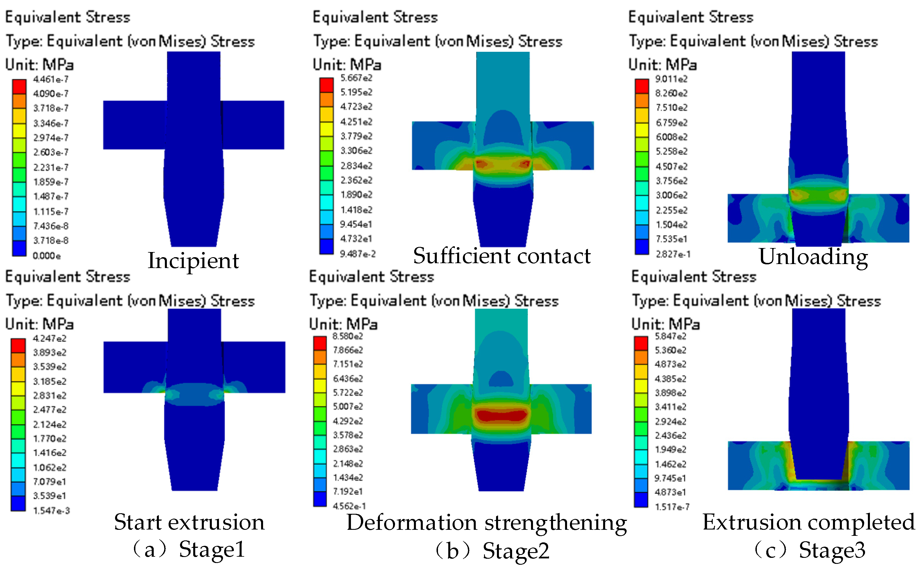
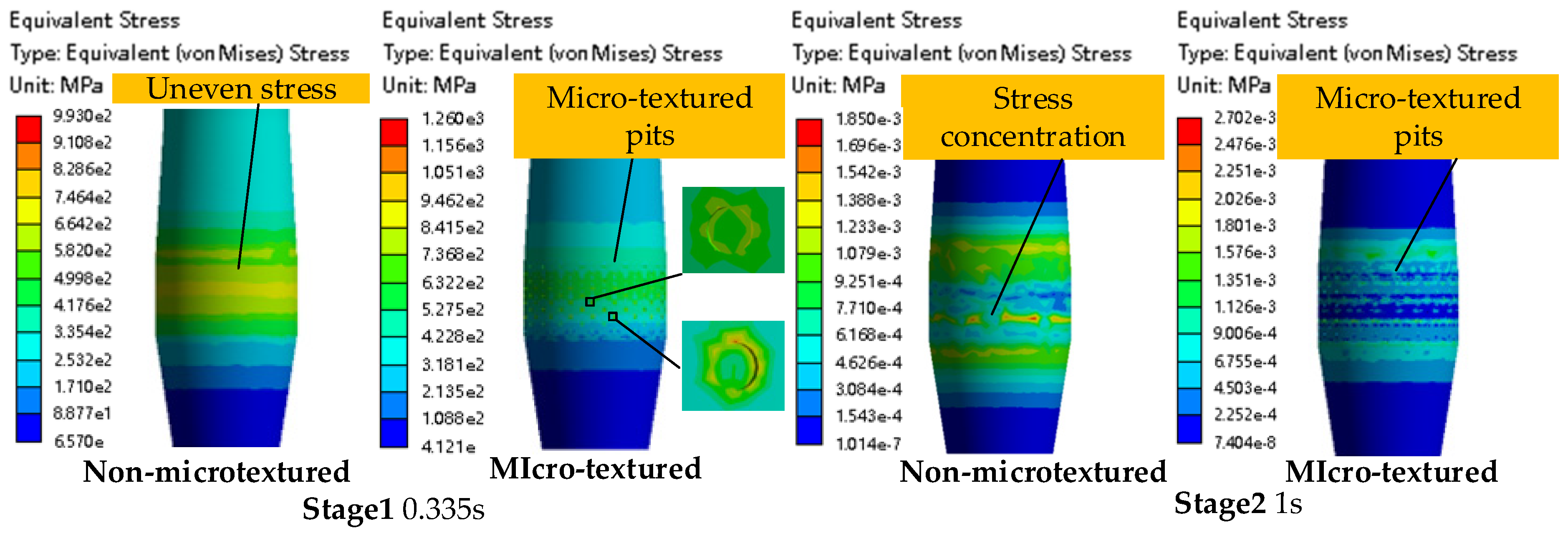
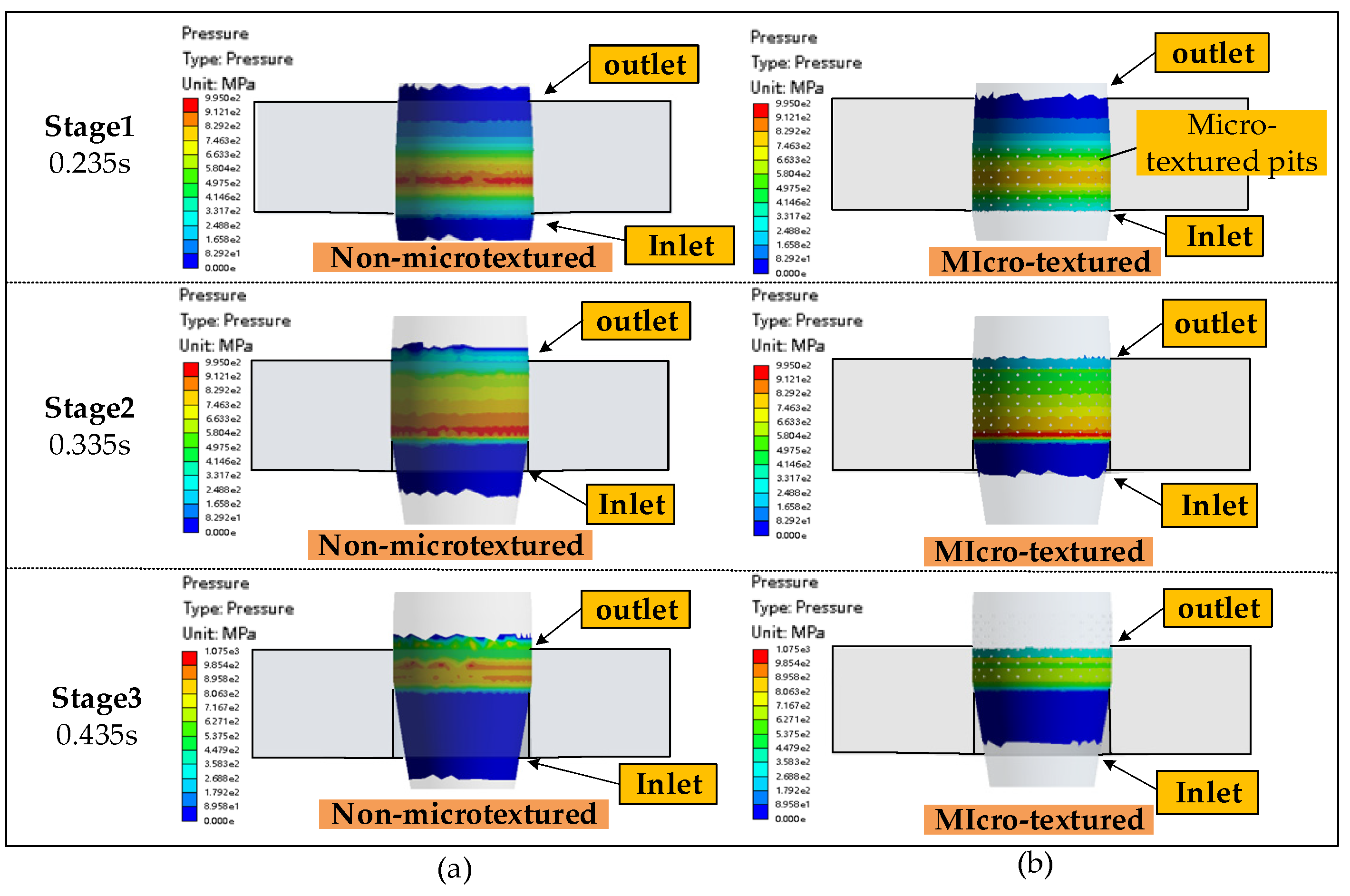
4.1. The Regulation Mechanism of the Micro-Texture on Mechanical Behavior

In order to explore the influence of the micro-texture on the anti-friction performance of the mandrel, a comparative simulation of the mandrel with and without micro-texture was carried out under the same boundary conditions. Figure 17 shows the von Mises stress distribution of the mandrel at different time nodes, and Figure 18 shows the contact pressure distribution of the mandrel–hole wall interface. The differences in the load transfer and contact response between the two are compared and analyzed.
As shown in Figure 17, during the first stage of the hole extrusion, the non-micro-textured mandrel exhibits a significant equivalent stress concentration, characterized by a high overall stress level and an uneven distribution, which increases the likelihood of forming local overload zones. In contrast, after the introduction of micro-textures, the equivalent stress in the working section of the mandrel is noticeably reduced, with a more uniform distribution and no large-scale abnormal stress concentrations, indicating an improved load diffusion capability.
It should be noted that the color scales of the cloud chart in Figure 17 are not unified due to differences in the maximum stress levels between the two cases. Therefore, identical colors may correspond to different stress values, which may limit direct visual comparisons. To clarify this and more precisely illustrate the local stress redistribution induced by micro-textures, a magnified view of the textured region is presented in Figure 17. This reveals that although some localized stress peaks appear around the edges of individual textures, these peaks are spatially dispersed and relatively uniformly distributed, thus avoiding the formation of any large-scale concentrated stress zones. At the end of the second strengthening stage, the micro-texture structure further improves the morphology of the contact interface, effectively suppresses the accumulation of stress in the surface layer, and significantly enhances the mechanical coordination of the interface.
The above results show that the traditional mandrel has the risk of structural instability due to the local load concentration during the strengthening process, and the micro-texture design can optimize the interface stress transfer path and improve the mechanical stability of the contact area while ensuring the strengthening effect. In order to further verify the mechanism, the synergistic regulation effect of the interface mechanical behavior was analyzed in combination with the contact pressure distribution in Figure 18.
As shown in Figure 18, in stages 1 and 2, the non-micro-textured mandrel shows an obvious peak contact pressure in the extrusion inlet area. The distribution is asymmetric along the circumferential direction, and there is a local load concentration. In contrast, the micro-textured mandrel shows a more uniform contact pressure distribution in both stages, and the extrusion inlet area forms a symmetrical and gentle pressure area, which effectively alleviates the local pressure surge problem. Stage 3 further shows that the micro-texture achieves the dispersion of the normal load by reducing the effective contact area and inhibiting the occurrence of the high contact pressure. Figure 19a shows the dynamic distribution of the contact pressure of the mandrel–hole wall interface with time, and further reveals the regulation of the micro-texture on the mechanical response of the interface during the whole extrusion process.
The comparison of contact pressure curves shows that the contact state of the non-micro-textured mandrel is unstable during the dynamic extrusion process, the pressure curve fluctuates violently, and the standard deviation of the contact pressure is 275.4 MPa; after the introduction of the micro-texture, the pressure curve fluctuates smoothly, the peak value of the contact pressure decreases, and the standard deviation decreases from 275.4 MPa to 162.4 MPa, which significantly improves the dynamic stability of the interface pressure. A further data integration analysis is performed to generate the histogram shown in Figure 19b. The results show that the peak contact pressure of the micro-textured mandrel is 29.7% lower than that of the non-micro-textured mandrel, and the standard deviation of the contact pressure is reduced by 41.0%. According to the wear model, the decrease in contact pressure helps to reduce the wear depth, while the decrease in the contact area delays the material removal rate and further enhances the wear resistance.

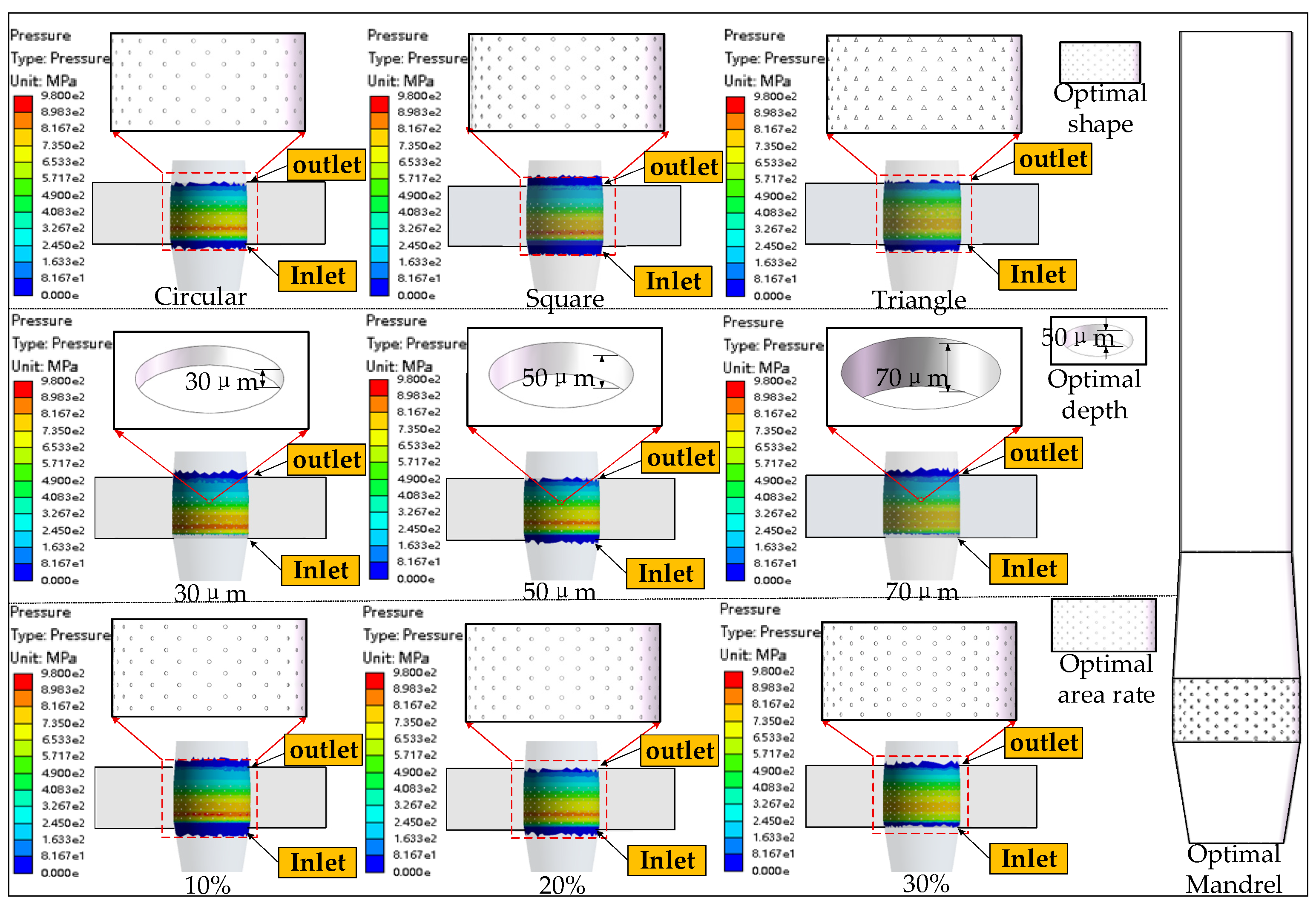
4.2. The Analysis of the Micro-Texture on the Friction Behavior of the Mandrel Interface

In order to systematically evaluate the regulation effect of the micro-texture structure on the friction behavior of the mandrel–hole wall interface, the friction stress data of the mandrel with and without micro-texture under the same displacement were extracted, and the friction stress–displacement curve was drawn. Combined with the typical friction stress cloud chart given in Figure 20, the mechanism of the micro-texture in optimizing the friction stress distribution was analyzed.
From the friction stress evolution curve shown in Figure 20, it can be seen that the friction stress of the non-micro-textured mandrel rises rapidly after the beginning of the extrusion, reaching a peak of 121.74 MPa at a displacement of about 9.7mm, and then fluctuates slightly. It rises again near the maximum displacement end and finally decreases gradually after 14.5mm. The stress curve in this process shows a multi-segment rise and fluctuation, which reflects that the interface contact friction state is more severe, and it is easy to form an unstable slip zone. In contrast, the friction stress rise process of the micro-textured mandrel is more stable. Although it reaches a slightly higher 129.10 MPa at 10.7mm, the overall change trend is more continuous, and there is no obvious sudden increase or decrease. Especially in the unloading process of the rear section, the stress decreases rapidly to 40.31 MPa, which reflects that the micro-textured mandrel can release the contact friction faster in the unloading stage, and the stress attenuation characteristics are obviously better than those of the non-textured mandrel.
Further combined with the cloud chart in Figure 20, it can be seen that there is a significant high-stress mutation area at the node of the non-micro-textured mandrel in the strengthening stage, which easily forms a wear-sensitive area. However, the friction stress distribution of the micro-textured mandrel is more uniform under the same node, and no obvious high-stress mutation area is observed, which shows that it has significant advantages in improving the force transmission path. There is an obvious concentration of high-stress areas in the unloading stage of the non-micro-textured mandrel, especially in the extrusion inlet and the middle of the mandrel. The micro-textured mandrel does not have a similarly prominent high-stress zone at the same stage, and the interface friction stress distribution is more uniform, reflecting the good adjustment effect of the texture structure on the contact state.
Based on the analysis of the friction stress–displacement curve and cloud diagram, the micro-texture reduces the average friction stress by 8.1% while improving the uniformity of the friction stress distribution. The results show that the micro-texture constructs a more stable friction force transmission path by guiding the redistribution of the interface contact area and the transfer of the shear load, thus realizing the collaborative optimization of the friction behavior at multiple scales and providing a strong guarantee for the service life and processing stability of the mandrel.

4.3. The Effect of the Micro-Textured Mandrel on the Hole Wall Strengthening Effect

In order to further explore the strengthening effect of the micro-textured mandrel in the process of hole extrusion strengthening, Figure 21 shows the distribution cloud diagram of the equivalent stress and tangential residual stress of the hole wall under the condition of no micro-texture and micro-texture, reflecting its mechanism of action in stress regulation and strengthening layer formation.
According to the plastic theory, the von Mises equivalent stress can be used to reflect the plastic deformation ability of the material. It can be seen from the Figure that the material produces non-uniform plastic strain along the thickness direction after the hole is extruded, forming a certain range of the residual stress layer. Under the action of the non-micro-textured mandrel, there is an obvious local stress concentration on the surface of the hole wall, especially from the extrusion inlet to the middle area. The equivalent stress shows an asymmetric distribution, which can easily cause local microcracks or fatigue source initiation. Although the stress area of the micro-textured mandrel is reduced as a whole, it effectively suppresses the local stress concentration. It forms a more continuous and symmetrical stress transition zone, indicating that it realizes the uniform transmission and diffusion of the load by disturbing the contact interface state. The distribution of the tangential residual stress in Figure 21b shows that the two kinds of mandrel structures form a high compressive stress zone at the extrusion inlet. In contrast, the residual compressive stress decreases rapidly from the middle and the extrusion outlet and gradually changes to the tensile stress state. Considering that the stress distribution in the extrusion outlet region is easily affected by many factors, such as the spring back, unloading path, and boundary condition disturbance, and the contribution of the strengthening layer structure to the overall fatigue life is relatively limited, the region is no longer analyzed in depth. In order to quantitatively analyze the depth of the compressive stress layer, the tangential residual stress curve is extracted along the paths A→B (extrusion inlet) and C→D (middle section) shown in Figure 21b. The results are shown in Figure 22.
In the extrusion inlet area, the residual compressive stress of the hole wall after strengthening with the non-micro-textured mandrel turns negative at 1.25 mm and returns to positive at 2.29 mm, forming a compressive stress layer of about 1.04mm. The maximum residual compressive stress is −29.5 MPa, and the strengthening layer is shallow, but the distribution is stable. In contrast, after the micro-textured mandrel is strengthened, the compressive stress zone begins at 1.04 mm and continues to 3.33 mm, the compressive stress layer expands significantly to 2.29 mm, and the peak value of the residual compressive stress increases to −88.6 MPa, indicating that the micro-texture helps to establish a deeper and stronger compressive stress zone at the extrusion inlet, and the strengthening effect is more sufficient, which is conducive to improving the fatigue resistance of the initial contact area of the orifice.
In the middle section, according to the theoretical calculation, the depth of the strengthened layer is about 2.15 mm. The simulation results show that the depth of the strengthening layer of the non-micro-textured mandrel is 2.92 mm, and the maximum residual compressive stress reaches −471.17 MPa, which exceeds the theoretical prediction value, indicating that the plastic strain in this area is sufficient. The depth of the strengthening layer in the middle of the micro-textured mandrel is 2.71 mm, and the peak residual compressive stress is −349.8 MPa. Although it is slightly lower than that without a micro-texture, it still exceeds the theoretical thickness of the strengthening layer, and the stress distribution curve is more gentle. The continuity of the strengthening layer is good, which meets the dual requirements of the plastic deformation uniformity and strengthening depth and ensures the effective strengthening of the central region.
In summary, the micro-textured mandrel achieves a significant deepening of the strengthening layer at the extrusion inlet and maintains a good thickness and stress continuity of the strengthening layer in the middle section. Although the peak compressive stress in some areas is slightly lower than that of the non-micro-textured mandrel, the overall strengthening layer covers the theoretical depth, and the structural integrity is good. This residual stress distribution characteristics meet the engineering strengthening requirements of the component fatigue resistance, which can effectively ensure the strengthening effect and service stability of the whole hole wall and verify the practical value and optimization potential of the micro-texture structure in the hole extrusion strengthening process.

5. Conclusions

In this study, a surface micro-texture-based structural optimization strategy is proposed to address the challenges of friction reduction and wear resistance in mandrels used for hole extrusion strengthening under high contact pressure conditions. A theoretical friction–wear model and a finite element simulation framework are established to systematically investigate the regulatory effects of micro-texture parameters on the interfacial contact behavior and strengthening performance. The main conclusions are as follows:
  • A mandrel structural system that integrates a micro-texture design with the hole extrusion strengthening process is developed. A collaborative design concept of anti-friction and strengthening is proposed, providing theoretical support and an engineering pathway for extending the mandrel’s service life.
  • A coupled friction–wear model incorporating micro-texture geometric parameters is constructed, revealing the mechanism by which the interfacial frictional stability and wear resistance are significantly enhanced under high contact pressure by reducing the peak contact stress and promoting a more uniform normal load distribution.
  • The parametric analysis confirms that the circular micro-texture with a depth of 50 μm and a 20% area ratio provides the most favorable combination, yielding an optimal contact uniformity, load transfer stability, and friction-reduction performance.
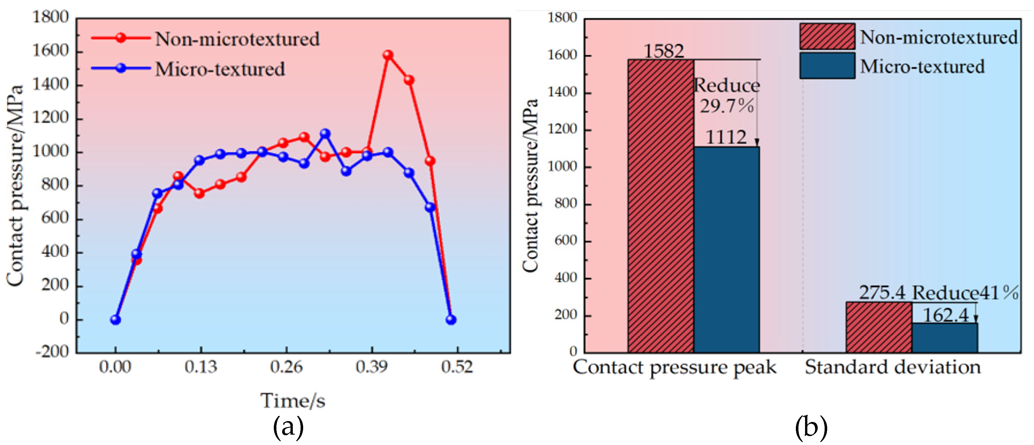
  • Finite element simulations further validate the effectiveness of the optimal configuration, showing that circular micro-textures reduce the peak contact pressure by 29.7%, the pressure standard deviation by 41.0%, and the average friction stress by 8.1%, significantly outperforming the non-textured reference group in alleviating the load concentration and enhancing the interfacial frictional stability.
In summary, this study proposes a theoretical and numerical framework to investigate the friction-reduction mechanism of micro-textured mandrels during hole cold expansion. The results provide valuable insights into the coupling regulation of the texture geometry and interfacial contact behavior, offering theoretical guidance for the structural design of high-performance mandrels. While the current framework assumes dry sliding conditions, future work will incorporate more realistic interfacial scenarios, including lubrication, frictional heating, and time-dependent material responses. In addition, complementary experiments—such as surface topography characterization, micro-hardness testing, and tribological evaluation—will be conducted to validate the model’s physical relevance and improve its engineering applicability. Building upon the foundation established in this work, we will continue to develop experimental platforms and refined models to explore these challenges. Ultimately, our aim is to realize an integrated solution for achieving low friction, stable strengthening, and an extended service life in cold expansion processes using advanced micro-textured mandrel designs.

Author Contributions

Conceptualization, Z.W. and G.L.; methodology, Z.W.; software, Z.W.; validation, G.L., L.Q. and C.L.; formal analysis, G.L.; investigation, J.L.; resources, G.L.; data curation, Z.W.; writing—original draft preparation, Z.W.; writing—review and editing, Z.W.; visualization, C.L.; supervision, G.L.; project administration, J.L.; funding acquisition, L.Q. All authors have read and agreed to the published version of the manuscript.

Funding

This research was funded by the Liaoning Provincial Science and Technology Department Project—Provincial Natural Science Foundation—PhD Start-up Fund, the Funder Guangming Lv, grant number 20240285; provincial department of education project—basic scientific research business expenses special (national defense military industry), the Funder Guangming Lv, grant number 20240205; and the Project Supported by the Foundation of Key Laboratory of Rapid Development and Manufacturing Technology for Aircraft (Shenyang Aerospace University), Ministry of Education, Shenyang, 110136, China, the Funder Guangming Lv, grant number 20240265.

Data Availability Statement

Data are contained within the article.

Conflicts of Interest

The authors declare no conflicts of interest.

References

  1. Wang, Y.L.; Zhu, Y.L.; Cao, Q. Progress and prospect of research on hole cold expansion technique. Acta Aeronaut. Astronaut. Sin. 2018, 39, 6–22. [Google Scholar]
  2. Jiang, Y.; Liu, X.; Wang, Y.; Cui, L.; Ji, G.; Liu, W. Investigation of Residual Stress Distribution and Fatigue of 7050-T7451 Alloy Hole Components with Laser Shock and Ultrasonic Extrusion. Metals 2024, 14, 597. [Google Scholar] [CrossRef]
  3. Wan, N.; Zhao, B.; Ding, W.; He, Q. Advancements in cold extrusion anti-fatigue manufacturing technology for connecting holes. Eng. Fract. Mech. 2025, 314, 110764. [Google Scholar] [CrossRef]
  4. Fu, Y.; Ge, E.; Su, H.; Xu, J.; Li, R. Cold expansion technology of connection holes in aircraft structures: A review and prospect. Chin. J. Aeronaut. 2015, 28, 961–973. [Google Scholar] [CrossRef]
  5. Xu, Y.; Wang, L.G.; Zhang, G.A.; Chen, T.; Jia, J. Influence of rubber surface roughness on the tribological performance of DLC films. Surf. Technol. 2023, 52, 225–232. (In Chinese) [Google Scholar]
  6. Hu, J.; Liu, J.; Liu, Z.; Feng, X. Research on the Effect of Micro-Pit Parameters on Tool Wear in Turning GH4169. Coatings 2025, 15, 543. [Google Scholar] [CrossRef]
  7. Zhang, C.; Chen, J.; Ji, B.; Zhou, J.; Zeng, L.; Yang, Y. Effect of Micro-Dimple Texture on the Tribological Performance of Brass with Titanium Nitride (TiN) Coating under Oil-Lubricated Conditions. Coatings 2024, 14, 119. [Google Scholar] [CrossRef]
  8. Yang, H.; Yang, S.; Tong, X. Study on the Matching of Surface Texture Parameters and Processing Parameters of Coated Cemented Carbide Tools. Coatings 2023, 13, 681. [Google Scholar] [CrossRef]
  9. Hamilton, D.B.; Walowit, J.A.; Allen, C.M. A theory of lubrication by microirregularities. J. Basic Eng. 1966, 88, 177–185. [Google Scholar] [CrossRef]
  10. Qin, L.; Lin, P.; Zhang, Y.; Dong, G.; Zeng, Q. Influence of surface wettability on the tribological properties of laser textured Co–Cr–Mo alloy in aqueous bovine serum albumin solution. Appl. Surf. Sci. 2013, 268, 79–86. [Google Scholar] [CrossRef]
  11. Wang, L.; Duan, J.; He, M.; Liu, Y.; Bao, Y. Study on antifriction mechanism of surface textured elliptical bearings. J. Tribol. 2023, 145, 011702. [Google Scholar] [CrossRef]
  12. Wan, Q.; Gao, P.; Zhang, Z. Friction and wear performance of lubricated micro-textured surface formed by laser processing. Surf. Eng. 2021, 37, 1523–1531. [Google Scholar] [CrossRef]
  13. Kitamura, K.; Makino, T.; Nawa, M.; Miyata, S. Tribological effects of punch with micro-dimples in blanking under high hydrostatic pressure. CIRP Ann. 2016, 65, 249–252. [Google Scholar] [CrossRef]
  14. Tang, H.; Ren, Y.; Xiang, J. Fully-coupled thermomechanical analysis for sliding contact between textured slipper and swashplate in axial piston pump. Int. J. Heat Mass Transf. 2020, 163, 120521. [Google Scholar] [CrossRef]
  15. Ji, J.; Zhou, Y.; Tian, P.; Chen, T.; He, Y. Numerical analysis of hydrodynamic lubrication of partially textured surfaces with dimples for journal bearing. Surf. Technol. 2021, 50, 214–220. (In Chinese) [Google Scholar]
  16. Awasthi, R.K.; Maan, J.S. Influence of surface texture on the performance of hydrodynamic journal bearing operating under turbulent regime. Tribol. Online 2021, 16, 99–112. [Google Scholar] [CrossRef]
  17. Andersson, P.; Koskinen, J.; Varjus, S.; Gerbig, Y.; Haefke, H.; Georgiou, S.; Zhmud, B.; Buss, W. Microlubrication effect by laser-textured steel surfaces. Wear 2007, 262, 369–379. [Google Scholar] [CrossRef]
  18. Zhang, J.; Chen, Y.; Xu, B.; Chao, Q.; Zhu, Y.; Huang, X. Effect of surface texture on wear reduction of the tilting cylinder and the valve plate for a high-speed electro-hydrostatic actuator pump. Wear 2018, 414–415, 68–78. [Google Scholar] [CrossRef]
  19. Ge, D.; Deng, J.; Duan, R.; Liu, Y.; Li, X.; Yue, H. Effect of micro-textures on cutting fluid lubrication of cemented carbide tools. Int. J. Adv. Manuf. Technol. 2019, 103, 3887–3899. [Google Scholar] [CrossRef]
  20. Kang, Z.; Fu, Y.; Kim, D.M.; Joe, H.E.; Fu, X.; Gabor, T.; Park, H.W.; Jun, M.B. From macro to micro, evolution of surface structures on cutting tools: A review. JMST Adv. 2019, 1, 89–106. [Google Scholar] [CrossRef]
  21. Atwal, J.C.; Pandey, R.K. Film thickness and friction investigations in a fluid film thrust bearing employing a newly conceived micro-texture on pads. ASME J. Tribol. 2021, 143, 061801. [Google Scholar] [CrossRef]
  22. Hua, X.; Puoza, J.C.; Zhang, P.; Yin, B.; Xie, X.; Din, J. Numerical simulation and experimental analysis of grease friction properties on textured surface. Iran. J. Sci. Technol. Trans. Mech. Eng. 2019, 43, 357–369. [Google Scholar] [CrossRef]
  23. Kishawy, H.A.; Salem, A.; Hegab, H.; Hosseini, A.; Balazinski, M. Micro-textured cutting tools: Phenomenological analysis and design recommendations. CIRP Ann. 2021, 70, 65–68. [Google Scholar] [CrossRef]
  24. Wan, N.; Zhao, B.; Ding, W.; He, Q. Research status and tendency on cold expansion anti-fatigue manufacturing technology for aircraft structural fastening holes. J. Manuf. Process. 2025, 141, 319–335. [Google Scholar] [CrossRef]
  25. Fu, J.; Zhang, T.; Wang, C.; Chen, C.; Zhang, T.; He, Y. Effect of cold expansion on the fatigue life of multi-hole 7075-T6 aluminum alloy structures under the pre-corrosion condition. Eng. Fail. Anal. 2024, 165, 1350–6307. [Google Scholar] [CrossRef]
  26. Papanikos, P.; Meguid, S.A. Elasto-plastic finite-element analysis of the cold expansion of adjacent fastener holes. J. Mater. Process. Technol. 1999, 92–93, 424–428. [Google Scholar] [CrossRef]
  27. Bowden, F.P.; Tabor, D. The friction and lubrication of solids. Am. J. Phys. 1951, 19, 428. [Google Scholar] [CrossRef]
  28. Wang, L.Y.; Chen, X.; Li, L. Calculation method and experimental study of friction plate wear in wet clutch. J. Guangxi Univ. (Nat. Sci. Ed.) 2017, 3, 826–833. (In Chinese) [Google Scholar]
  29. Vorholt, J.; Shimizu, T.; Kobayashi, H.; Heinrich, L.; Flosky, H.; Vollertsen, F.; Yang, M. In-situ observation of lubricant flow on laser textured die surface in sheet metal forming. Procedia Eng. 2017, 207, 1877–1882. [Google Scholar] [CrossRef]
  30. He, M.; Huang, C.H.; Wang, X.X.; Yang, F.; Zhang, N.; Li, F.G. Assessment of the local residual stresses of 7050-T7452 aluminum alloy in microzones by the instrumented indentation with the Berkovich indenter. J. Mater. Eng. Perform. 2017, 26, 4923–4932. [Google Scholar] [CrossRef]
  31. Pottirayil, A.; Menezes, P.L.; Kailas, S.V. A parameter characterizing plowing nature of surfaces close to Gaussian. Tribol. Int. 2010, 43, 370–380. [Google Scholar] [CrossRef]
  32. Hu, S.; Zheng, L.; Guo, Q.; Ren, L. Influence of cross-grooved texture shape on tribological performance under mixed lubrication. Coatings 2022, 12, 305. [Google Scholar] [CrossRef]
  33. Kim, J.Y.; Yoon, S.C.; Jin, B.-K.; Jeon, J.-H.; Hyun, J.-S.; Lee, M.-G. Friction characteristics of low and high strength steels with galvanized and galvannealed zinc coatings. Materials 2024, 17, 5031. [Google Scholar] [CrossRef]
  34. Huang, J.; Zhu, J.; Zhou, K.; Liu, Z.; Huang, Y. Probing wear mechanism of Ti6Al4V micro-textured surfaces processed by laser-assisted grinding. J. Alloys Compd. 2025, 1010, 178272. [Google Scholar] [CrossRef]
  35. Hu, J.; Wei, J.; Feng, X.; Liu, Z. Research on Wear of Micro-Textured Tools in Turning GH4169 during Spray Cooling. Lubricants 2023, 11, 439. [Google Scholar] [CrossRef]
  36. Sheng, Z.; Zhu, H.; He, Y.; Shao, B.; Sheng, Z.; Wang, S. Tribological Effects of Surface Biomimetic Micro–Nano Textures on Metal Cutting Tools: A Review. Biomimetics 2025, 10, 283. [Google Scholar] [CrossRef]
  37. Liu, K.; Zhou, L.; Yang, X.; Li, M.; Wang, W.; Zhu, W. Finite element simulation of the cold expansion process with split sleeve in 7075 aluminum alloy. J. Inst. Eng. (India) Ser. C 2021, 102, 361–374. [Google Scholar] [CrossRef]
Figure 1. Hole extrusion strengthening principle diagram.
Coatings 15 00789 g001
Figure 2. Non-micro-textured mandrel interface friction mechanism model.
Coatings 15 00789 g002
Figure 3. Adhesion wear schematic diagram.
Coatings 15 00789 g003
Figure 4. Micro-textured mandrel interface friction mechanism model.
Coatings 15 00789 g004
Figure 5. The influence trend of different micro-texture parameters on the friction coefficient μ 2 .
Coatings 15 00789 g005
Figure 6. Flow chart of friction and wear mechanism controlled by micro-texture.
Coatings 15 00789 g006
Figure 7. Three-dimensional response surface diagram.
Coatings 15 00789 g007
Figure 8. Flow chart of contact pressure coupling evolution.
Coatings 15 00789 g008
Figure 9. The surface structure of organisms: (a) grooves on the scale shell of the pangolin; (b) the arrow-like texture on the shark skin; and (c) the pit structure on the shell of the dung beetle [36].
Coatings 15 00789 g009
Figure 10. Micro-texture structure design schematic diagram.
Coatings 15 00789 g010
Figure 11. Micro-texture structure design schematic diagram.
Coatings 15 00789 g011
Figure 12. Hole extrusion assembly model.
Coatings 15 00789 g012
Figure 13. The grid division of the simulation model.
Coatings 15 00789 g013
Figure 14. Simulation of hole extrusion strengthening process (a) Extrusion stage. (b) Strengthening stage. (c) Unloading stage.
Coatings 15 00789 g014
Figure 15. Contact pressure distribution cloud diagram of different micro-texture parameters.
Coatings 15 00789 g015
Figure 16. Contact pressure distribution curves of different micro-texture parameters.
Coatings 15 00789 g016
Figure 17. Equivalent stress distribution characteristics cloud chart.
Coatings 15 00789 g017
Figure 18. Contact pressure distribution cloud chart. (a) No micro-texture mandrel. (b) Micro-texture mandrel.
Coatings 15 00789 g018
Figure 19. Contact pressure evolution law. (a) Contact pressure curve. (b) Contact pressure histogram.
Coatings 15 00789 g019
Figure 20. Mandrel–hole wall interface friction stress curve and cloud chart.
Coatings 15 00789 g020
Figure 21. Hole wall plastic deformation cloud chart (a) Equivalent stress. (b) Residual stress.
Coatings 15 00789 g021
Figure 22. The evolution law of tangential residual stress. (a) The tangential residual stress curve at the extrusion inlet. (b) The tangential residual stress curve in the middle section.
Coatings 15 00789 g022
Table 1. Material parameters of the hole template and mandrel parts.
NameMaterialDensity (kg/m3)Elastic Modulus
(MPa)
Poisson Ratio
Hole templateAL-7050283071,7000.33
MandrelW18Cr4V8000220,0000.3
Table 2. Micro-texture parameter combinations used in the finite element simulations.
GroupShapeDepth (μm)Area Ratio (%)Remark
G1Circular5020Baseline group
G2Square5020Shape variation
G3Triangle5020Shape variation
G4Circular3020Depth variation
G5Circular7020Depth variation
G6Circular5010Area ratio variation
G7Circular5030Area ratio variation
Disclaimer/Publisher’s Note: The statements, opinions and data contained in all publications are solely those of the individual author(s) and contributor(s) and not of MDPI and/or the editor(s). MDPI and/or the editor(s) disclaim responsibility for any injury to people or property resulting from any ideas, methods, instructions or products referred to in the content.

