Article

Experimental Investigation on the Erosion Resistance Characteristics of Compressor Impeller Coatings to Water Droplet Impact

1
Department of Propulsion Technology, AUDI Hungaria Faculty of Vehicle Engineering, Széchenyi István University, H-9026 Győr, Hungary
2
Department of Materials Science and Technology, AUDI Hungaria Faculty of Vehicle Engineering, Széchenyi István University, H-9026 Győr, Hungary
3
Mechanical Engineering Department, Faculty of Technical and Human Sciences, Sapientia Hungarian University of Transilvania, Corunca, Calea Sighisoarei nr.2, RO-540485 Targu-Mures, Romania
4
Department of Automotive Engineering and Transports, Faculty of Automotive Engineering, Mechatronics, and Mechanics, Technical University of Cluj-Napoca, Muncii blvd. 103-105, RO-400114 Cluj-Napoca, Romania
5
Institute of Automotive Engineering, Faculty of Mechanical Engineering, Brno University of Technology, Technická, 2896/2, 616 69 Brno, Czech Republic
*
Author to whom correspondence should be addressed.
Coatings 2025, 15(7), 767; https://doi.org/10.3390/coatings15070767 (registering DOI)
Submission received: 25 May 2025 / Revised: 24 June 2025 / Accepted: 27 June 2025 / Published: 28 June 2025
(This article belongs to the Section Ceramic Coatings and Engineering Technology)

Abstract

This study presents a comparative analysis of the water droplet erosion resistance of three compressor wheels coated with Ni-P and Si-P layers. The tests were conducted using a custom-developed experimental apparatus in accordance with the ASTM G73-10 standard. The degree of erosion was monitored through continuous precision mass measurements, and structural changes on the surfaces of both the base materials and the coatings were examined using a Zeiss Crossbeam 350 scanning electron microscope (SEM). Hardness values were determined using a Vickers KB 30 hardness tester, while the chemical composition was analysed using a WAS Foundry Master optical emission spectrometer. Significant differences in erosion resistance were observed among the various compressor wheels, which can be attributed to differences in coating hardness values, as well as to the detachment of the Ni-P layer from the base material under continuous erosion. In all cases, water droplet erosion led to a reduction in the isentropic efficiency of the compressor—measured using a hot gas turbocharger testbench—with the extent of efficiency loss depending upon the type of coating applied. Although blade protection technologies for turbocharger compressor impellers used in the automotive industry have been the subject of only a limited number of studies, modern technologies, such as the application of certain alternative fuels and exhaust gas recirculation, have increased water droplet formation, thereby accelerating the erosion rate of the impeller. The aim of this study is to evaluate the resistance of three different coating layers to water droplet erosion through standardized tests conducted using a custom-designed experimental apparatus.

1. Introduction

The erosion of high-speed rotating impellers by water droplets and the development of solutions to mitigate this phenomenon present challenges that are actively addressed across various engineering fields today. The physical nature of this phenomenon was first described by Worthington [1] as early as the 1870s. However, significant research interest emerged with the widespread adoption of steam power plants in the 1950s. In efforts to improve energy production efficiency, increasingly large turbine structures were constructed, and steam was expanded through so many stages that condensation occurred on the blades in the final stages. This led to substantial erosion due to high-velocity droplet impacts [2]. In this area of research, common approaches to enhance erosion resistance include the use of various steel and titanium alloys (e.g., TihourAl4V, X12CrNiMoV12-3), as well as post-mold coatings such as WC-12Co and WC-17Co applied via high-velocity oxygen fuel (HVOF) processes [3,4,5,6,7].
Similarly, wind power plants are employing increasingly larger and faster-rotating structures to boost energy generation efficiency. As a result, minimizing the weight of the rotating blades has become essential, leading to the use of lightweight metals and, increasingly, polymer-based materials. However, these materials are also susceptible to significant erosion caused by the impact of rain or airborne particles, potentially reducing power generation efficiency by up to 20%–25% [8,9]. To address this, post-mold protective coatings are commonly applied. These coatings offer the advantages of not requiring modifications to the base material and being removable and easily replaceable during maintenance.
In a comprehensive review, Herring et al. [10] outlined various protective techniques, coating materials, and deposition technologies, highlighting their respective advantages and limitations. Engel [11] identified the erosion of aircraft components by rain as an emerging challenge, primarily caused by high-speed impacts. Within the field of aeronautics, Tobin et al. [12] investigated water droplet erosion of aircraft nose radomes, where the need for radio-frequency transparency often compromises material resistance to erosion. Additionally, to mitigate erosion-related power loss in aircraft engines, Bonu et al. [13] compared several material grades, discussing their respective strengths and weaknesses.
Application-independent research on material structures for solid-state erosion has also yielded significant results in reducing erosion rates. In their study, Debasish et al. [14] demonstrated that torch input power is the most critical factor influencing erosive wear. Specifically, increasing the input power significantly reduced the erosion rate when Mo-TiN coatings were applied to Al-Si substrates of turbocharger compressor wheels using the ASP process.
In recent years, the incorporation of ceramic particle reinforcements, such as SiC and TiC, into Ni-based composite coatings has received growing attention due to their beneficial effects on wear and corrosion resistance. Xie et al. [15] reported that laser-cladded Ni60 coatings containing SiC and Ti3SiC2 exhibited markedly improved wear behavior on IN718 alloy. In a related study, Zhang et al. [16] investigated how varying SiC concentrations affected the properties of electrodeposited Ni-SiC coatings. They found that an optimal particle content led to microstructural refinement and enhanced wear resistance. Similarly, Natarajan et al. [17] reported comparable improvements in pulse electrodeposited Ni–SiC nanocomposites applied to cast iron cylinder liners, suggesting that SiC reinforcement can be effectively utilized across various substrates and deposition techniques.
Despite these advancements, little is currently known about the performance of electroless Si-P coatings under high-velocity liquid impact conditions—particularly on lightweight aluminum alloys such as EN AW-2618A. This study aims to address that gap.
In the field of automotive engineering, low-pressure exhaust gas recirculation (LP-EGR) is an increasingly widespread technology that can significantly reduce NOx emissions from internal combustion engines. In the case of gasoline engines, it can also reduce specific fuel consumption at certain operating points [18,19,20,21]. However, a major drawback of this technology is that the water vapor content in the exhaust gas tends to condense into liquid, resulting in high-velocity impacts with the turbocharger’s compressor blades, which can cause significant erosion. Compressor impellers are typically manufactured from aluminum alloys, as minimizing the rotational inertia of the rotor structure is critical. However, these alloys do not offer sufficient resistance to erosion caused by water droplets, making further research in this area essential. An additional concern is the increasing use of certain alternative fuels, as their combustion generally produces a higher specific water vapor content due to a greater hydrogen-to-carbon ratio. This can lead to more condensation and, consequently, more severe erosion for the same energy output [22,23,24,25,26].
The number of experimental studies on water droplet erosion of turbocharger compressor wheels reported in the literature is very limited. Although some studies [27,28] have yielded important findings, they lack detailed methodological descriptions, making it difficult to ensure comparability. Furthermore, key material parameters, such as the chemical composition of the base material and/or coating, as well as their hardness values, are often omitted, despite their significant influence on the extent of erosion.
The aim of the present study is to provide a comparative analysis that addresses the limitations of previous publications by offering a detailed description of the experimental conditions related to the erosion of turbocharger compressor impellers caused by water droplet impact, as well as by identifying the material properties most relevant to erosion resistance. An additional objective is to evaluate the effectiveness of Ni-P and Si-P coatings in mitigating water droplet erosion. Detailed erosion tests were conducted on three commercially available compressor wheels with an identical geometry and base material, but with different coatings, using a dedicated test apparatus conforming to the ASTM G73-10 standard [29]. The erosion process was characterized through precision mass measurements and microscopic imaging, supplemented by standard hardness testing and chemical composition analysis. Finally, changes in the isentropic efficiency of the eroded compressor impellers were assessed using a mapping procedure on a specialized hot gas turbocharger test bench.

2. Materials and Methods
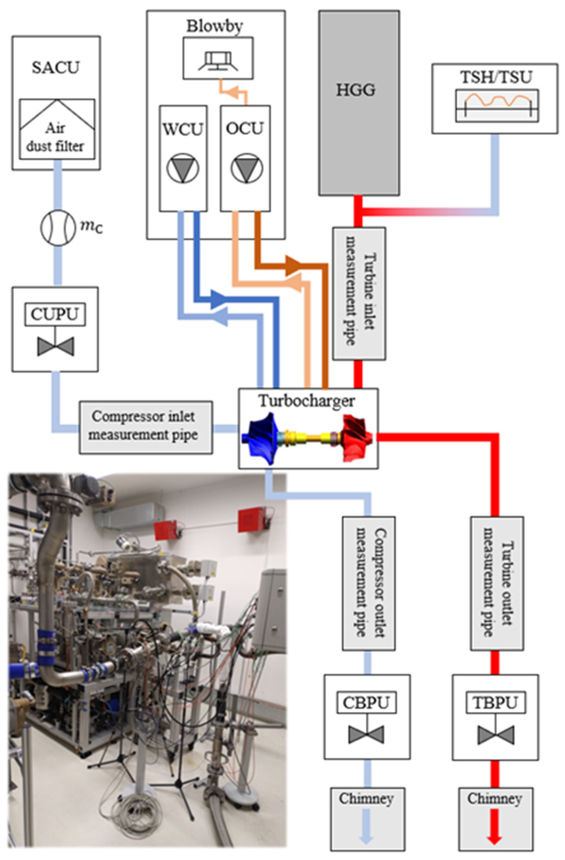
To ensure reproducibility and comparability, the tests conducted in the present study were prepared in accordance with the requirements of ASTM G73-10 [29]. This standard specifies that surfaces subjected to water erosion must undergo hardness testing prior to experimentation, and that the tests must be performed under precisely controlled parameter settings.

2.1. Test Apparatus

To enable precise control of the test parameters over a wide range, a dedicated test apparatus was developed, comprising the main components illustrated in the schematic diagram below (Figure 1).
According to the ASTM G73-10 standard [29], the velocity range of water droplets impacting solid surfaces should be between 60 and 600 m/s. In the present tests, an impact velocity of 250 m/s was applied, based on the vectorial sum of the circumferential speed of the compressor impeller and the laminar speed of the water droplets, assuming a 90° impact angle. This value reflects a commonly encountered velocity condition for compressor wheels of similar size and application. It is important to note that the present study does not aim to investigate the influence of impact velocity on erosion. Instead, the focus is on comparing the erosion resistance of different coating materials under identical test conditions. The impact velocity used in this study was calculated using Equation (1) proposed by Hattori et al. [30].
v i m p = v D 2 + v C 2
where v i m p is the velocity of impact, v D is the velocity of the colliding water droplet, and v C is the circumferential speed at the point of impact of the rotating target. The circumferential velocity of the impacted point on the blades ( v C ) was achieved through compressed air propulsion regulated by a velocity sensor and a PID controller. The water droplet velocity ( v D ) was generated using a pressurized hydrophore tank, which—unlike the pump-based systems commonly reported in the literature—eliminates pressure pulsations and maintains a constant pressure level throughout testing. During the experiments, the maximum deviation of the impact velocity from the target value was within ±0.3%. Achieving uniform droplet size and detecting their collision frequency were also critical. For this purpose, a water droplet generator (WDG) unit was employed. This device utilizes piezoelectric excitation to break the continuous water jet—supplied by the hydrophore tank—into uniformly sized droplets, based on the Rayleigh–Plateau instability principle [31]. In the present study, a 375 μm pinhole, a water pressure of 4 bar (relative), and an excitation frequency of 10 kHz were used to generate droplets with a diameter of approximately 845 μm and a size distribution of ±3% (as validated by the manufacturer). The uniformity of droplet size and formation frequency was confirmed using a high-speed camera (HSC) in front of a dark, scaled background, as shown in Figure 2. The 10 kHz frequency was selected because, according to the Rayleigh–Plateau instability principle [31], a water jet under 4 bar (rel.) pressure breaks up into droplets within the 7.2–21.8 kHz frequency range. The chosen value of 10 kHz corresponds to a water flow rate that realistically reflects the condensed water conditions observed upstream of the compressor in practical applications.

2.2. Samples

The tests were conducted on three compressor wheels, each featuring a 47 mm inducer diameter and identical geometry. All samples were fabricated from the same base material, with a consistent chemical composition and manufacturing processes. The base material was identified as EN AW-2618A (AlCu2Mg1.5Ni), in accordance with EN 573-3:2019+A2:2023 [32], and validated using a WAS Foundry-Master optical emission spectrometer. The reported values represent the average of five measurements per sample, with low standard deviations. However, the applied coatings differed in their material properties. The coating was applied using an electroless nickel deposition process, which is an autocatalytic chemical reduction method. Surface preparation included degreasing, alkaline etching, desmutting with nitric acid, and a double zincate treatment to ensure the strong adhesion of the nickel layer. The plating bath consisted of nickel sulfate as the nickel source, sodium hypophosphite (NaH2PO2) as the reducing agent, lactic acid as the complexing agent, and trace amounts of thiourea as a stabilizer. Deposition was carried out at a temperature of 88–90 °C, with the bath maintained at pH 5.0–5.2 under moderate agitation to ensure uniform coating. After plating, the parts were rinsed and neutralized. The coating was applied over the entire compressor wheel, not limited to the erosion zone. Coating thickness was measured and validated on polished cross-sections after testing, using a Zeiss Crossbeam 350 SEM at five points along the erosion zone. The results are presented in Table 1.
Surface roughness was not directly measured after coating but is suggested for inclusion in future work.
For Sample 3, Si particles were incorporated into the coating. The presence of silicon was confirmed by an EDX analysis (4.98 wt%), indicating successful co-deposition. No post-treatment or heat curing was performed following the coating application. In this study, each coating type was tested using a single specimen, primarily due to the complexity and resource-intensive nature of the experimental setup. Therefore, the results should be interpreted as indicative rather than statistically conclusive. Future work will focus on expanding the test series with multiple replicates to support statistically robust conclusions.

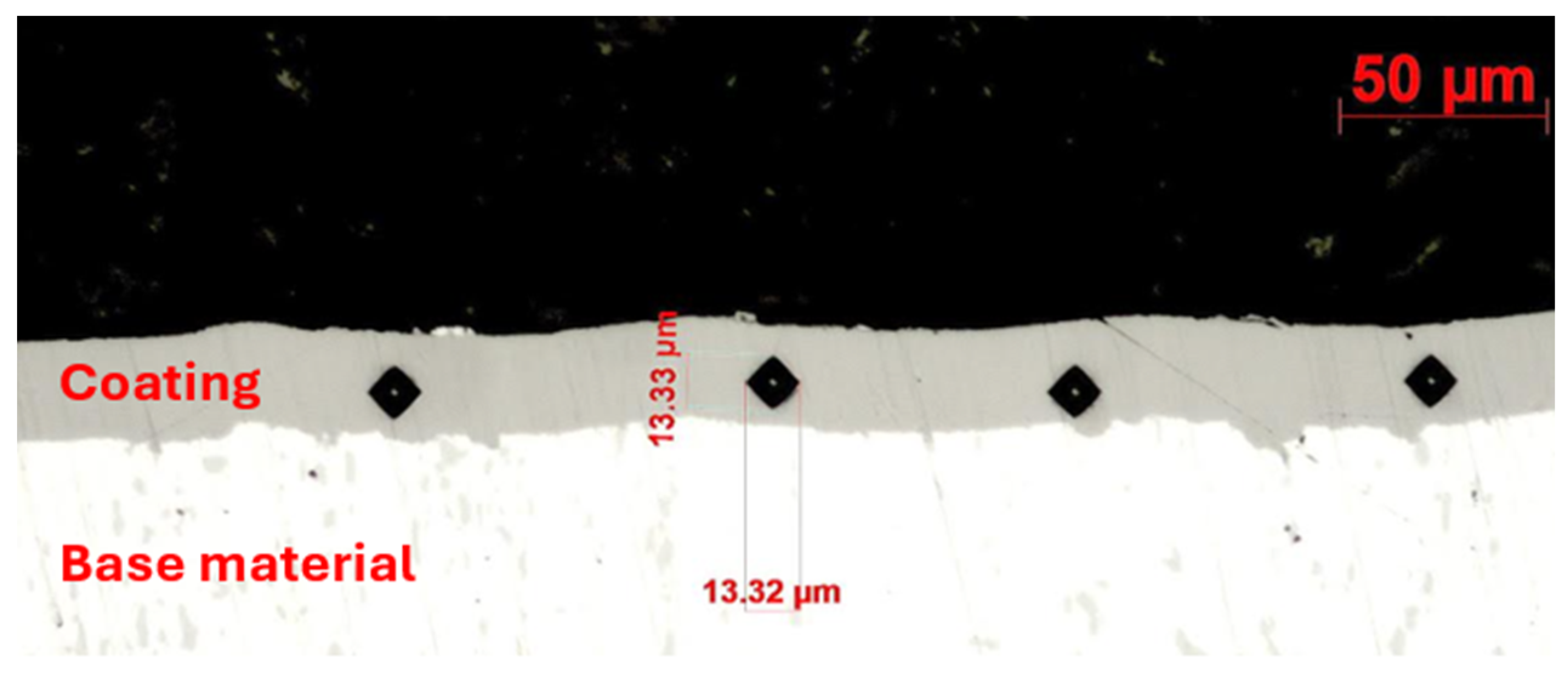
2.3. Hardness Measurement

To ensure that the chemical composition of the base material and coatings accurately reflected the tested specimens, these structural properties were verified through destructive testing. In all three cases, the hardness of the base material was determined by averaging five Vickers impressions per sample, measured using a KB 30 hardness tester at a 10 kp load, in accordance with ISO 6507-1:2024 [33]. The hardness of the coatings was assessed by averaging four indentations per sample on ground cross-sections, as shown in Figure 3. Measurements were performed using a Buehler Micromet microhardness tester with the Vickers method at a 0.05 kp load. Prior to testing, the cross-sections were embedded and then ground using SiC abrasive papers of increasing grit sizes (P80, P180, P320, P500, P800, and P1200), followed by a three-step polishing process employing 9 µm, 3 µm, and OP-S suspensions. During hardness testing, the indentation size was used to determine the appropriate load. Initial attempts to measure the coatings using HV0.1 resulted in excessively large indents that extended beyond the coating layer. Consequently, the load was reduced to HV0.05, yielding indents that were fully contained within the coating and suitable for evaluation. This difference is clearly visible in the corresponding microscopic images.
Table 2 summarizes the hardness values of the different samples of the base material and coating.
The hardness values of the base material across all tested samples are observed to be nearly identical. In contrast, the coating hardness of Sample 3 is significantly greater than that of Samples 1 and 2, exhibiting an increase of approximately 18%.

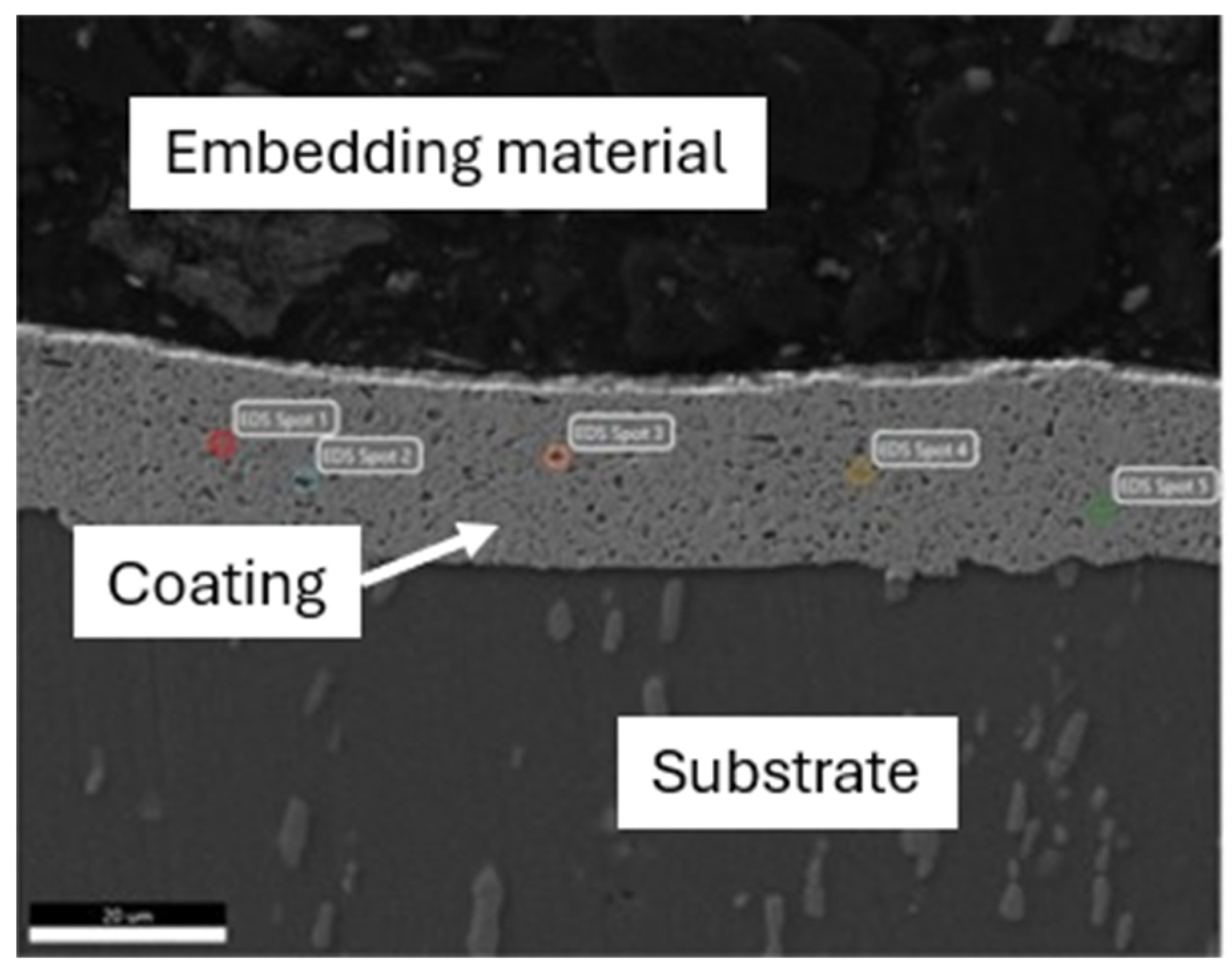
2.4. Chemical Composition Detection of the Coatings

The cause of the hardness difference between the coatings was elucidated by determining their chemical compositions after the erosion tests, using a Zeiss Smart EDX system integrated with a Zeiss Crossbeam SEM. The weight percentages of the elements in each coating were calculated by averaging the measurements taken at five points near the erosion zone, as exemplified in Figure 4.
Measurements were performed at an accelerating voltage of 20 kV, with a working distance corresponding to a takeoff angle of 37°, and a magnification of ×2220. Each spectrum was acquired over a live time of 100 s, with an amplifier time of 3.84 µs. The system’s energy resolution was 128.4 eV. Elemental composition was determined through spot analyses using a silicon drift detector (SDD). Table 3 summarizes the detected elements in terms of weight percentage. During the analysis, oxygen, carbon, and nitrogen were also detected, but only in negligible amounts (less than 5 wt% combined).
For Samples 1 and 2, the same constituent elements were detected, with only slight differences in their weight percentages, which corresponded to a hardness difference of approximately 5 HV. However, for Sample 3, Si was also detected at 4.98 wt%, an element known for its high hardness. Its presence corresponds to an increase in hardness of nearly 18% compared to the other two samples.

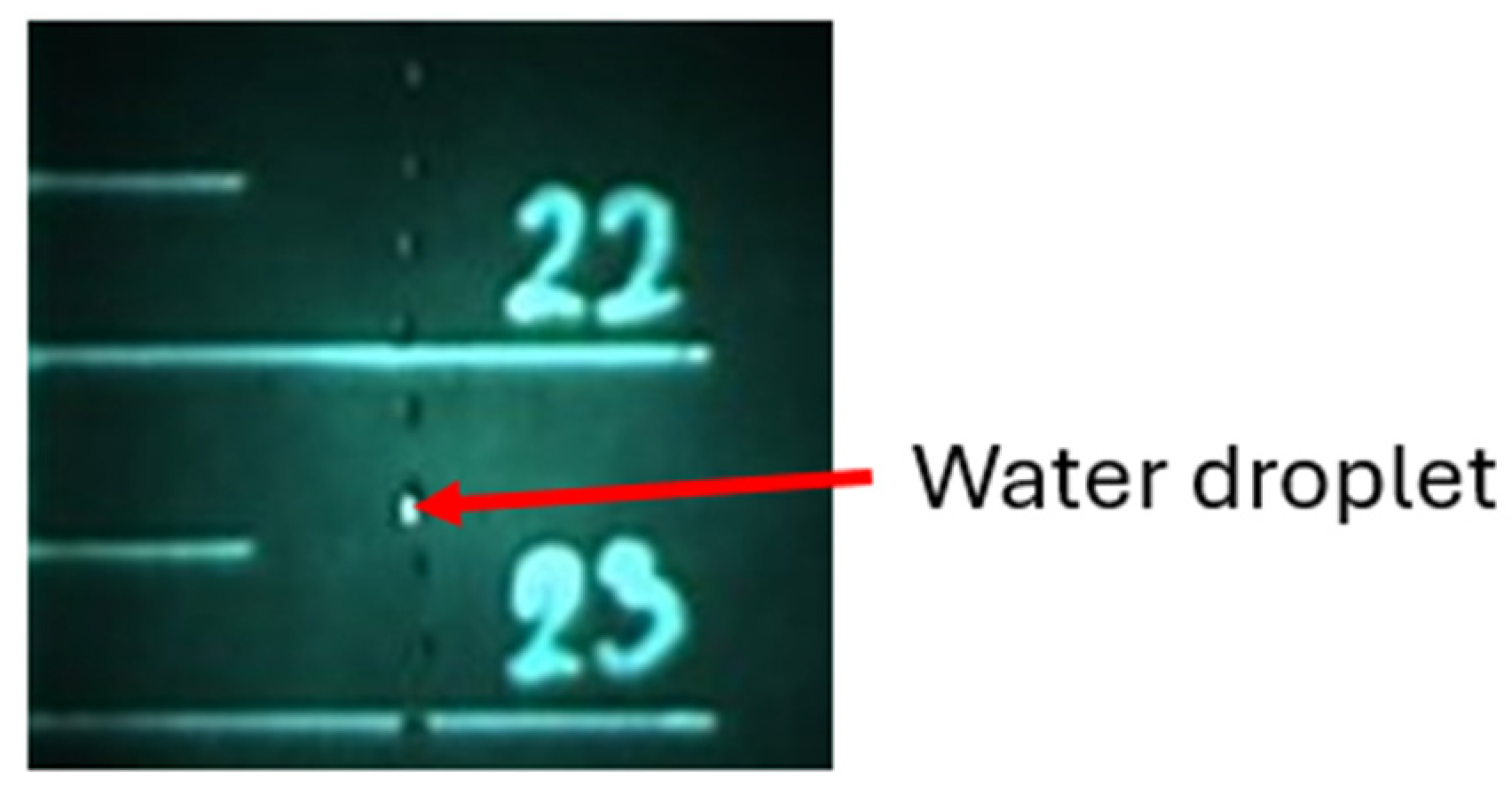
2.5. Erosion Detection

Following the installation and commissioning process, the investigation commenced. The erosion tests were periodically interrupted for each coating type to measure the amount of material loss using a Sartorius ultra-precision mass measurement device (accuracy: 0.001 g). All tests were conducted for an equal duration across the three samples. Samples 1 and 2 experienced significant damage after approximately 9.72 × 10⁸ water droplet impacts. To analyze the change in isentropic efficiency between the original and damaged turbocharger-equipped samples, testing was halted at this point. Continuing the tests beyond this stage could have introduced a high risk of severe imbalance and potential destruction [34], which would have compromised the generation of the isentropic efficiency curves.
To investigate the water droplet erosion damage mechanisms in greater detail, the samples were examined using a Zeiss Crossbeam 350 scanning electron microscope (SEM). Measurements were taken at a resolution of 3072 × 2304 pixels and an accelerating voltage of 6.0 kV to obtain qualitative images of the eroded specimens.

2.6. Compressor Isentropic Efficiency Measurement

The damage sustained by the samples influenced the isentropic efficiency of the compressor, thereby affecting both the thermal efficiency and fuel consumption of the engine in which it is employed. Variations in this parameter were observed for all three samples using the hot gas turbocharger test bench located at Széchenyi István University (Figure 5). The evaluation was based on a comparison between the initial measurement values and those obtained after sample degradation, recorded across three speed lines: 150 m/s, 200 m/s, and 250 m/s. These selected velocities correspond to realistic operating conditions. Speeds below 150 m/s are not relevant for practical applications of this turbocharger, while testing above 250 m/s posed increased risks to the damaged samples, due to the high level of imbalance.
All measurements were performed using an automated control program, which ensured the consistent regulation of all parameters influencing the test. For each speed line, six measurement points were defined. In each case, the subsequent measurement point was selected only after the isentropic efficiency of the compressor remained stable within a ±0.1% variation for a minimum of 90 s. The isentropic efficiency was calculated based on Equation (2), using temperature and pressure sensors installed upstream and downstream of the compressor.
η c o m p _ i s = T 1 p 2 p 1 κ 1 κ T 1 T 2 T 1
where η c o m p _ i s denotes the isentropic efficiency of the compressor, T 1 is the compressor inlet temperature, T 2 is the compressor outlet temperature, p 1 is the compressor inlet pressure, p 2 is the compressor outlet pressure, and κ is an adiabatic exponent, which is typically assumed to be 1.4 for air. Table 4 lists all sensors used for determining the isentropic efficiency of the compressor, along with their respective specifications.

3. Results and Discussion

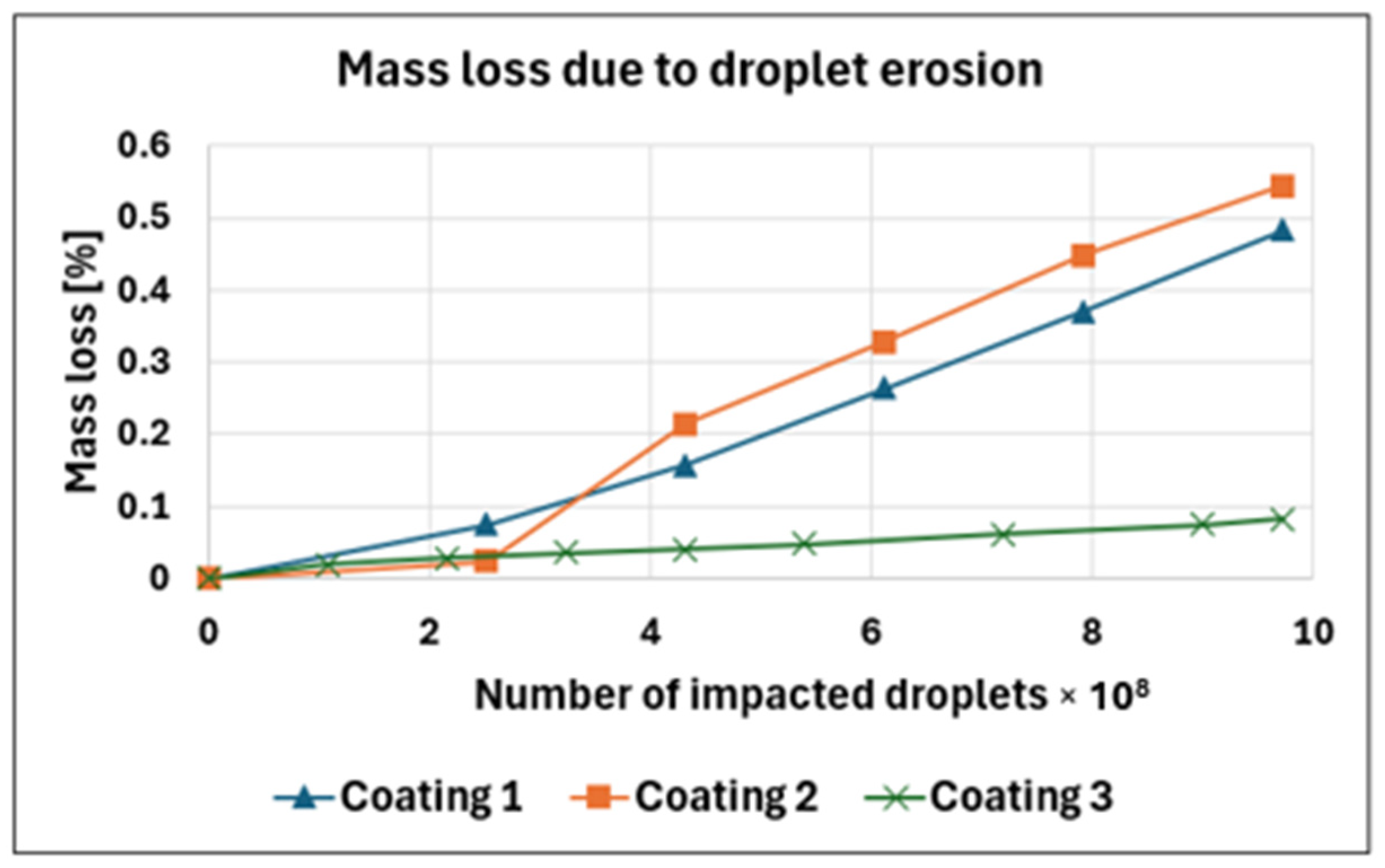
3.1. Mass Loss and Hardness

The extent of erosion was assessed both visually and through mass measurements at defined intervals. During the evaluation of the first sample, structural damage was observed after the impact of approximately 9.72 × 10⁸ water droplets, reaching a severity that posed a risk of complete structural failure. To ensure that the erosion on the samples could be properly analyzed, continuation of the experiment beyond this point was deemed unacceptable, and the test was therefore suspended. For the sake of comparability, the experiments on the remaining samples were also terminated at the same stage. The extent of damage observed at the end of testing for each sample is shown in Figure 6.
As shown in Figure 6, Sample 1 (Figure 6a) and Sample 2 (Figure 6b) exhibited similar levels and patterns of erosion. A notable observation for both samples was the complete coating delamination and base material wear on the backside of the blades (Figure 6c). In contrast, Sample 3 demonstrated significantly less erosion (Figure 6d) and no coating delamination on the backside (Figure 6e).
The results of the mass loss measurements are presented in Figure 7, where the x-axis represents the number of water droplet impacts, and the y-axis indicates the mass loss as a percentage relative to the original mass of the compressor wheel.
Several studies have established that increasing the hardness of a solid enhances its resistance to water erosion [36,37,38,39]. The mass loss curves presented in Figure 7 corroborate this relationship. However, additional effects are also evident. Up to approximately 2.5 × 10⁸ impacted water droplets, Sample 1 exhibited the greatest wear. Sample 2 showed a slightly lower material loss, which is presumably attributable to the higher nickel and phosphorus content of its coating, conferring greater ductility. As demonstrated by Ahmad et al. [40], ductility, alongside hardness, significantly influences erosion resistance by increasing the material’s elasticity and its capacity to absorb impact energy elastically. In the case of Sample 3, the higher coating hardness is the dominant factor, resulting in a substantially lower wear rate compared to Samples 1 and 2.

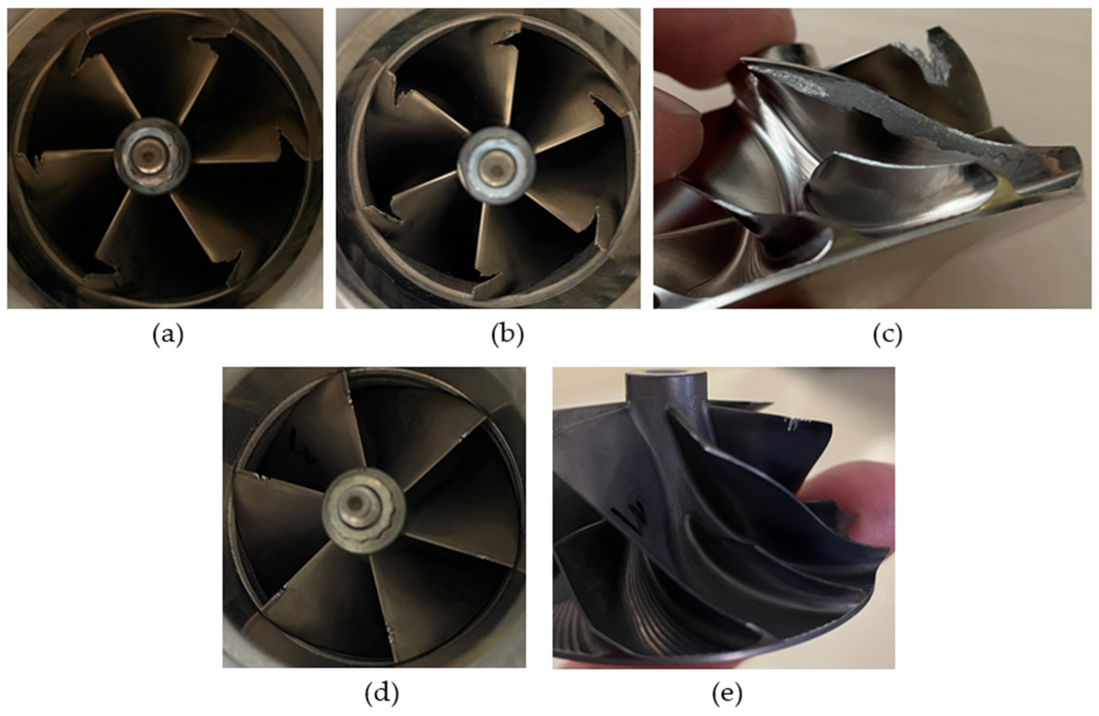
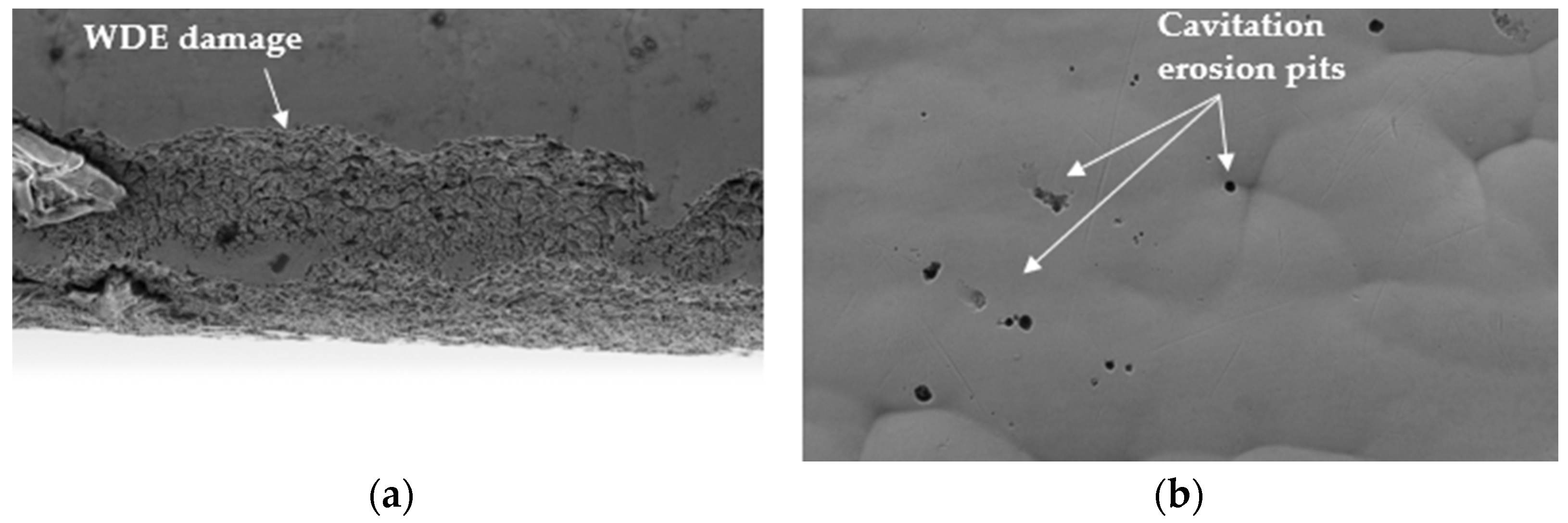
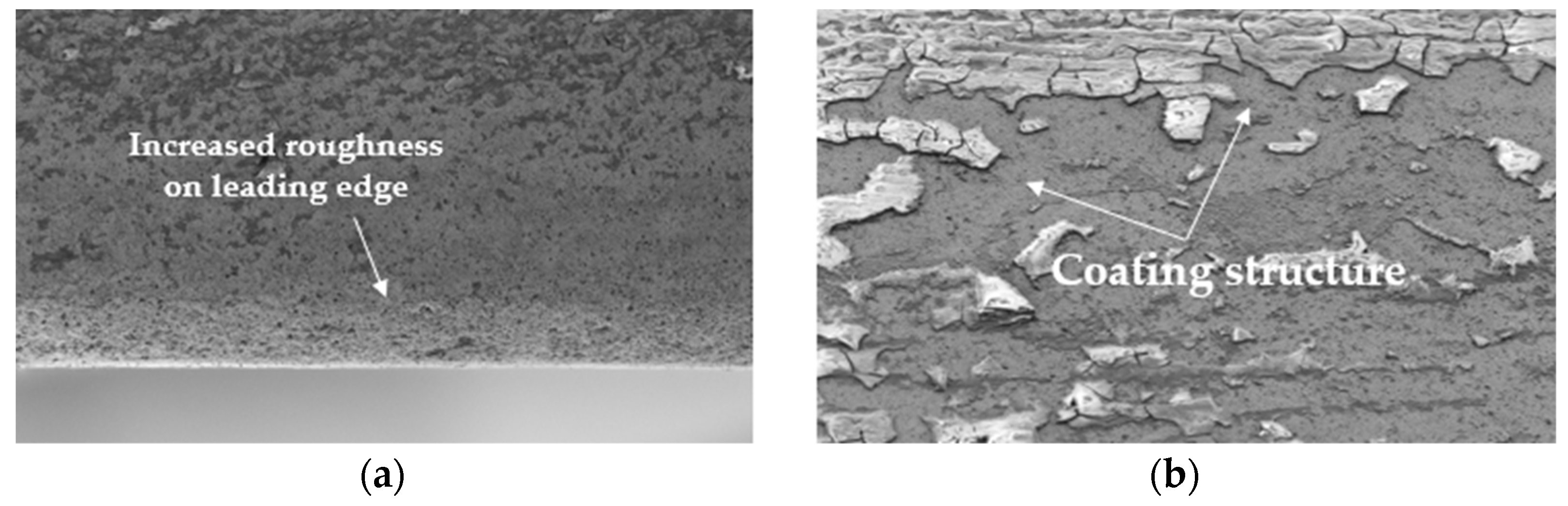
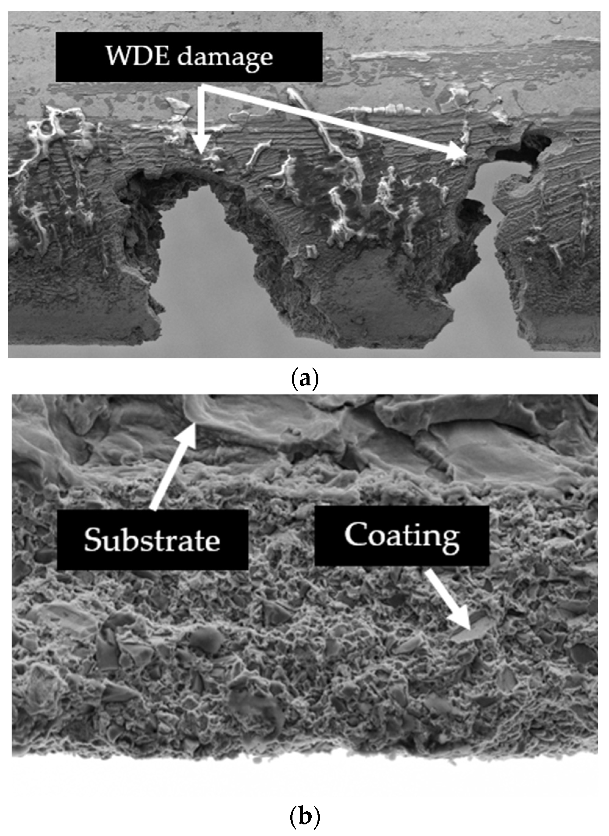
3.2. Wear Analysis with SEM

The damage mechanisms were examined in detail using scanning electron microscopy (SEM), employing the same settings described in the previous section. The measurement time points were selected to capture the early stages of erosion. It is important to note that all compressor impellers featured a Ni–P-based coating. However, Sample 3 also included Si particles incorporated into the coating to enhance its hardness.
The SEM images presented in Figure 8a,b show the eroded surface of Sample 1 (Sample 2 exhibited a very similar wear pattern) after approximately 2.5 × 10⁸ water droplet impacts. Figure 8a illustrates the wear caused by droplet impingement on the leading edge. It can be clearly observed that the coating has started to deteriorate, although the substrate remains covered. In Figure 8b, small pits are visible on the inner side of the leading edge, presumably caused by cavitation. This observation aligns with the findings of Mann [41], who reported a similar phenomenon during the initial stages of a water erosion test on laser-treated stainless steel. However, in the present study, the formation and confirmation of this phenomenon require further investigation. As shown in Figure 8a,b, the coating remained well-adhered to the substrate. Due to its high hardness and the resulting improved erosion resistance, only minimal material loss was observed.
Figure 9a shows the condition of the specimen after approximately 9.72 × 10⁸ water droplet impacts. The results indicate that erosive wear had progressed to the point where a significant amount of material was removed from the blades. Notably, a portion of the coating had detached from the substrate near the water droplet erosion (WDE) zone, directly exposing the underlying material to further impingement. This likely accelerated the erosion process, as the base material possesses a significantly lower hardness.
The detachment of the coating is attributed to poor adhesive bonding with the substrate. Under repeated impacts, the coating gradually delaminated, allowing water droplets to penetrate the interface. As delamination advanced, microcracks initiated at stress concentration points—visible in Figure 9b—further compromising the structural integrity of the coating and resulting in the removal of larger fragments over time.
Figure 10a,b illustrate the condition of Sample 3 after approximately 2.5 × 10⁸ water droplet impacts. Compared to Samples 1 and 2, the observed damage appears to be less severe, which can be attributed to its 18% higher hardness. However, increased surface roughness was identified along the leading edge within the impact zone. It is important to note that no clear evidence of erosive wear initiation was observed during the examination.
Figure 11a,b illustrate that, after approximately 9.72 × 10⁸ water droplet impacts, material removal on Sample 3 initiated at the leading edge of the compressor blade. However, the extent of erosion is notably less severe compared to Samples 1 and 2. It is also noteworthy that no cavitation erosion pits were observed on the surface, which may be attributed to the superior hardness properties of the material, potentially enhancing its resistance to cavitation-induced damage.
Furthermore, the coating on Sample 3 remained fully adhered to the substrate surface. This phenomenon is presumably due to the presence of Si particles, which increase the adhesion strength between the coating and substrate, harden the matrix, and inhibit crack propagation toward the interface. This observation aligns with findings reported in related studies. For instance, Zhang et al. [16] confirmed the beneficial effects of ceramic reinforcements such as Si on the hardness and wear resistance of Ni-based coatings. They demonstrated that the incorporation of Si particles into Ni60 matrix coatings significantly enhanced the wear performance and corrosion resistance of Ti–6Al–4V substrates due to the formation of hard Ti5Si3 phases. Although their study focused on laser-cladded coatings on titanium substrates, the mechanisms and reinforcement effects observed are comparable to the improvements documented in the present investigation.
It is important to note that information regarding the substrate preparation prior to coating was not provided by the manufacturer. Based on microscopic images, it can be assumed that a similar preparation process and quality were employed. However, further investigations are recommended to analyze the effects of the base material’s surface preparation.

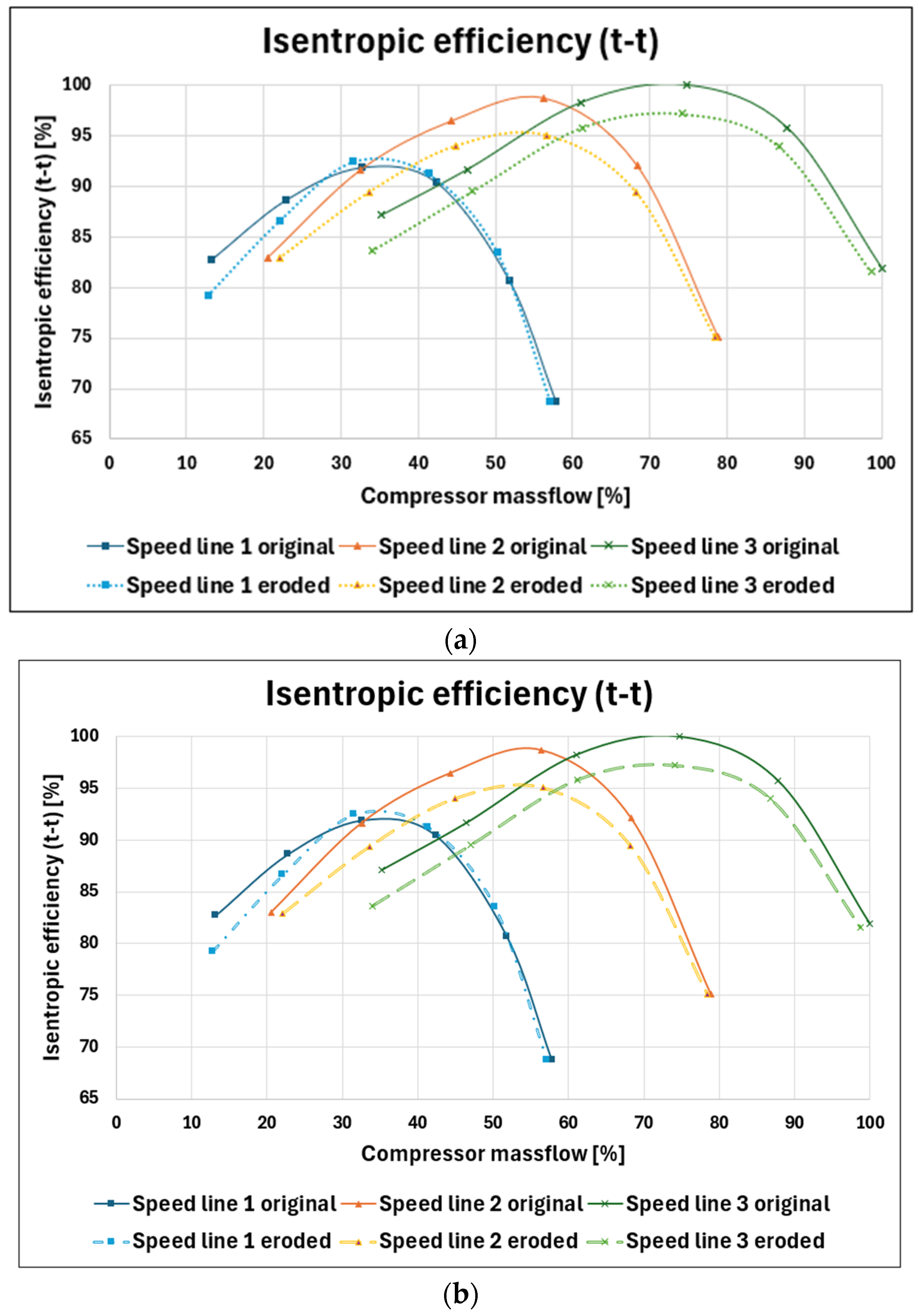
3.3. Compressor Isentropic Efficiency Analysis

To analyze the effect of erosion on turbocharger performance, compressor characteristic curves were determined using a turbocharger test bench located at Széchenyi István University. Compressor characteristic curves were evaluated at three speed lines within the central operating regime of the impeller to comprehensively assess the isentropic efficiency of the compressor. For each case, comparisons were made between the isentropic efficiency values in the original and eroded states of the turbocharger compressor impeller. Figure 12a,b illustrate the results of this analysis. For Sample 3, the reduction in isentropic efficiency was negligible and within the measurement uncertainties. In contrast, Samples 1 and 2 exhibited a significant reduction in isentropic efficiency of approximately 2.5%. This decrease in efficiency corresponds to increased fuel consumption and, consequently, higher CO2 emissions from the engine. The results for Samples 1 and 2 were nearly identical, as shown in Figure 12a,b.
In addition to the significant reduction in isentropic efficiency, a noticeable shift in the surge (left end of the curves) and choke (right end of the curves) limits was also observed at each speed line, further contributing to increased engine fuel consumption.

4. Conclusions

This study investigated the performance of three turbocharger compressor impeller coatings under high-velocity water droplet impact. The impellers shared identical geometries and were operated on the same turbocharger. However, each featured coatings with different chemical compositions. The primary objective was to present a detailed and accurate analysis in accordance with the ASTM G73-10 standard [29] to support reproducibility and comparability in future testing. The samples originated from the same type of turbocharger, though limited information was available prior to testing.
Samples 1 and 2 exhibited nearly identical erosion rates, attributable to their similar coating and base material hardness values. Although the chemical compositions of their coatings were also nearly identical, Sample 2 contained slightly higher nickel content, resulting in marginally improved erosion resistance. In contrast, Sample 3 demonstrated significantly reduced erosion over the same test interval. A chemical composition analysis revealed the presence of 4.98 wt% silicon (Si) in the coating, which led to an 18% increase in hardness compared to Samples 1 and 2. Additionally, scanning electron microscopy (SEM) confirmed that Sample 3 exhibited no coating delamination, likely due to enhanced adhesion properties associated with the Si particles, whereas significant delamination occurred in Samples 1 and 2.
A comparative analysis of the isentropic efficiency of the compressors showed that erosion in Samples 1 and 2 resulted in a measurable efficiency reduction of approximately 2.5%, which is considered significant across the three tested speed lines.
Overall, the findings emphasize the critical role of coating hardness, adhesion strength, and microstructure in mitigating water droplet erosion in turbocharged systems. Future work should examine the influence of substrate surface preparation prior to coating and explore alternative coating chemistries for improved erosion resistance. Given the availability of a custom-designed test apparatus, future research may also investigate the effects of impact velocity, droplet count, and angle of collision on the erosion behavior in coatings with varying compositions and mechanical properties.

Author Contributions

Conceptualization, R.T. and I.Z.; methodology, R.T.; software, R.T.; investigation, R.T. and B.D.; material analysis, R.T. and I.P.-M.; microscope analysis, N.K., M.Z.T., and I.B.; writing-original draft preparation, R.T. and N.K.; writing-review and editing, C.T.-N. and P.N.; project administration, R.T. All authors have read and agreed to the published version of the manuscript.

Funding

This article is published in the framework of the project “Production and Validation of Synthetic Fuels in Industry-University Collaboration”, project number “ÉZFF/956/2022-ITM_SZERZ”. This article is supported by the EKÖP-24-UNIVERSITY RESEARCH FELLOWSHIP PROGRAM of the Ministry for Culture and Innovation from the source of the National Research, Development and Innovation Fund.

Institutional Review Board Statement

Not applicable.

Informed Consent Statement

Not applicable.

Data Availability Statement

Data are available upon request from the corresponding author.

Conflicts of Interest

The authors declare no conflict of interest.

Abbreviations

The following abbreviations are used in this manuscript:
ASPAtmospheric Plasma Spray
CBPUCompressor Backpressure Unit
CUPUCompressor Under-pressure Unit
EDXEnergy-Dispersive X-ray Spectroscopy
η c o m p _ i s Compressor isentropic efficiency
HGGHot Gas Generator
HSCHigh-speed Camera
HVVickers Hardness
HVOFHigh-velocity Oxygen Fuel
κAdiabatic exponent
LP-EGRLow-pressure Exhaust Gas Recirculation
m C Compressor mass flow
OCUOil Conditioning Unit
OP-SOxide-Polishing Silica
p 1 Compressor inlet pressure
p 2 Compressor outlet pressure
PIDProportional-Integral-Derivative
SACUSuction Air Conditioning Unit
SDStandard Deviation
SDDSilicon Drift Detector
SEMScanning Electron Microscope
T 1 Compressor inlet temperature
T 2 Compressor outlet temperature
TBPUTurbine Backpressure Unit
TSHThermo-Shock Heater
TSUThermo-Schock Unit
u 1 , 2 , 3 Circumferential velocity of the compressor
v C Circumferential velocity at the impact point
v D Water droplet velocity
v i m p Impact velocity of water droplet
WCUWater Conditioning Unit
WDGWater Droplet Generator
wtWeight ratio

References

  1. Worthington, A.M. On the forms assumed by drops of liquids falling vertically on a horizontal plate. R. Soc. 1877, 25, 171–178. [Google Scholar] [CrossRef]
  2. Ahmad, M.; Schatz, M.; Casey, M. Experimental investigation of droplet size influence on low pressure steam turbine blade erosion. Wear 2013, 303, 83–86. [Google Scholar] [CrossRef]
  3. Mahdipoor, M.; Tarasi, F.; Moreau, C.; Dolatabadi, A.; Medraj, M. HVOF sprayed coatings of nano-agglomerated tungsten-carbide/cobalt powders for water droplet erosion application. Wear 2015, 330–331, 338–347. [Google Scholar] [CrossRef]
  4. Gerdes, C.; Karimi, A.; Bieler, H.W. Water droplet erosion and microstructure of laser-nitrided Ti-6Al-4V. Wear 1995, 186, 368–374. [Google Scholar] [CrossRef]
  5. Di, J.; Wang, S.; Yan, X.; Jiang, X.; Lian, J.; Zhang, Z.; Xie, Y. Experimental Research on Water Droplet Erosion Resistance Characteristics of Turbine Blade Substrate and Strengthened Layers Materials. Materials 2020, 13, 4286. [Google Scholar] [CrossRef]
  6. Zhang, Z.; Zhang, D.; Xie, Y. Experimental study on water droplet erosion resistance of coatings (Ni60 and WC-17Co) sprayed by APS and HVOF. Wear 2019, 432, 202950. [Google Scholar] [CrossRef]
  7. Jones, L. Low angle scouring erosion behaviour of elastomeric materials. Wear 2011, 271, 1411–1417. [Google Scholar] [CrossRef]
  8. Dashtkar, A.; Hadavinia, H.; Sahinkaya, M.N.; Williams, N.A.; Vahid, S.; Ismail, F.; Turner, M. Rain erosion-resistant coatings for wind turbine blades: A review. Polym. Polym. Compos. 2019, 27, 443–475. [Google Scholar] [CrossRef]
  9. Slot, H.; Gelinck, E.; Rentrop, C.; van der Heide, E. Leading edge erosion of coated wind turbine blades: Review of coating life models. Renew. Energy 2015, 80, 837–848. [Google Scholar] [CrossRef]
  10. Herring, R.; Dyer, K.; Martin, F.; Ward, C. The increasing importance of leading-edge erosion and a review of existing protection solutions. Renew. Sustain. Energy Rev. 2019, 115, 109367. [Google Scholar] [CrossRef]
  11. Engel, O.G. Waterdrop collision with solid surfaces. J. Res. Natl. Bur. Stand. 1955, 54, 281–298. [Google Scholar] [CrossRef]
  12. Tobin, E.; Young, T.; Raps, D.; Rohr, O. Comparison of liquid impingement results from whirling arm and water-jet rain erosion test facilities. Wear 2011, 271, 2625–2631. [Google Scholar] [CrossRef]
  13. Bonu, V.; Barshilia, H.C. High-Temperature Solid Particle Erosion of Aerospace Components: Its Mitigation Using Advanced Nanostructured Coating Technologies. Coatings 2022, 12, 1979. [Google Scholar] [CrossRef]
  14. Debasish, D.; Panigrahi, A.; Sengupta, P.; Bajpai, S. Erosive wear characteristic of Mo-TiN composite coatings on turbocharger compressor wheel using Taguchi experimental design. Mater. Today Proc. 2022, 66, 534–539. [Google Scholar] [CrossRef]
  15. Xie, X.-M.; Liu, X.-B.; He, B.-M.; Zhang, F.-Z.; Liang, J.-X.; Liu, X.-Y.; Zheng, J. Laser cladding Ni60-SiC/Ti3SiC2 self-lubricating composite coatings on IN718 alloy: Wear mechanisms and oxidation behaviors. Wear 2024, 560, 205611. [Google Scholar] [CrossRef]
  16. Zhang, Y.; Liu, Z.; Lv, Z.; Cao, J.; Tong, Y.; Sun, M.; Cui, C.; Wang, X. Effect of SiC and TiC content on microstructure and wear behavior of Ni-based composite coating manufactured by laser cladding on Ti–6Al–4V. Wear 2024, 552, 205431. [Google Scholar] [CrossRef]
  17. Natarajan, P.; Sakthivel, P.; Vijayan, V.; Chellamuthu, K. Characterization of Pulse Electrodeposited Ni-SiC Nanocomposite Coating on Four Stroke Internal Combustion Engine Cast Iron Cylinder Liner. Silicon 2024, 16, 6193–6208. [Google Scholar] [CrossRef]
  18. Lapuerta, M.; Ramos, Á.; Fernández-Rodríguez, D.; González-García, I. High-pressure versus low-pressure exhaust gas recirculation in a Euro 6 diesel engine with lean-NOx trap: Effectiveness to reduce NOx emissions. Int. J. Engine Res. 2018, 20, 155–163. [Google Scholar] [CrossRef]
  19. Serrano, J.P.; Piqueras, P.; Navarro, R.; Tarí, D.; Meano, C.M. Development and verification of an in-flow water condensation model for 3D-CFD simulations of humid air streams mixing. Comput. Fluids 2018, 167, 158–165. [Google Scholar] [CrossRef]
  20. Desantes, J.M.; Luján, J.M.; Pla, B.; Soler, J.A. On the combination of high-pressure and low-pressure exhaust gas recirculation loops for improved fuel economy and reduced emissions in high-speed direct-injection engines. Int. J. Engine Res. 2012, 14, 3–11. [Google Scholar] [CrossRef]
  21. Siokos, K.; Koli, R.; Prucka, R.; Schwanke, J.; Miersch, J. Assessment of cooled low pressure EGR in a turbocharged direct injection gasoline engine. SAE Int. J. Engines 2015, 8, 1535–1543. [Google Scholar] [CrossRef]
  22. Venu, H.; Subramani, L.; Raju, V.D. Emission reduction in a DI diesel engine using exhaust gas recirculation (EGR) of palm biodiesel blended with TiO2 nano additives. Renew. Energy 2019, 140, 245–263. [Google Scholar] [CrossRef]
  23. Moroz, S.; Bourgoin, G.; Luján, J.M.; Pla, B. Acidic condensation in low pressure EGR systems using diesel and biodiesel fuels. SAE Int. J. Fuels Lubr. 2009, 2, 305–312. [Google Scholar] [CrossRef]
  24. D’ambrosio, S.; Mancarella, A.; Manelli, A. Utilization of Hydrotreated Vegetable Oil (HVO) in a Euro 6 Dual-Loop EGR Diesel Engine: Behavior as a Drop-In Fuel and Potentialities along Calibration Parameter Sweeps. Energies 2022, 15, 7202. [Google Scholar] [CrossRef]
  25. Szwaja, S.; Piotrowski, A.; Szwaja, M.; Musial, D. Thermodynamic Analysis of the Combustion Process in Hydrogen-Fueled Engines with EGR. Energies 2024, 17, 2833. [Google Scholar] [CrossRef]
  26. Johar, T.; Hsieh, C.-F. Design Challenges in Hydrogen-Fueled Rotary Engine—A Review. Energies 2023, 16, 607. [Google Scholar] [CrossRef]
  27. Karstadt, S.; Werner, J.; Münz, S.; Aymanns, R. Effect of water droplets caused by low pressure EGR on spinning compressor wheels. In Proceedings of the 19th Supercharging Conference Dresden, Aachen, Germany, 17–18 September 2014. [Google Scholar]
  28. Wittmann, T.; Lück, S.; Bode, C.; Friedrichs, J. On the Impact of Condensation and Liquid Water on the Radial Turbine of a Fuel Cell Turbocharger. Machines 2022, 10, 1053. [Google Scholar] [CrossRef]
  29. ASTM G73-10; Standard Practice for Liquid Impingement Erosion Testing. ASTM International: West Conshohocken, PA, USA, 2010.
  30. Hattori, S.; Kakuichi, M. Effect of impact angle on liquid droplet impingement erosion. Wear 2013, 298–299, 1–7. [Google Scholar] [CrossRef]
  31. Rayleigh, L. On the instability of jets. Proc. Lond. Math. Soc. 1878, 1, 4–13. [Google Scholar] [CrossRef]
  32. EN 573-3:2019+A2:2023; Aluminum and Aluminum Alloys—Chemical Composition and Form of Wrought Products—Part 3: Chemical Composition and Form of Products (EN 573-3:2019). European Committee for Standardization: Brussels, Belgium, 2019.
  33. ISO 6507-1:2024; Metallic Materials—Vickers Hardness Test—Part 1: Test Method (1 kgf to 100 kgf Load). International Organization for Standardization: Geneva, Switzerland, 2024.
  34. Rácz, B.; Pesthy, M.; Sass, P.; Rohde-Brandenburger, J. Experimental investigation of vibroacoustic behavior of an automotive turbocharger with semi-floating bearing. In Vehicle and Automotive Engineering; Springer: Singapore, 2020; pp. 245–255. [Google Scholar]
  35. DIN EN 60751:2023-06; Industrial Platinum Resistance Thermometers (EN 60751:2008). Deutsches Institut für Normung/Beuth Verlag: Berlin, Germany, 2009.
  36. Kirols, H.; Kevorkov, D.; Uihlein, A.; Medraj, M. The effect of initial surface roughness on water droplet erosion behaviour. Wear 2015, 342, 198–209. [Google Scholar] [CrossRef]
  37. Luiset, B.; Sanchette, F.; Billard, A.; Schuster, D. Mechanisms of stainless steels erosion by water droplets. Wear 2013, 303, 459–464. [Google Scholar] [CrossRef]
  38. Shaik, R.A.; Ibrahim, M.E.; Gujba, A.K.; Pugh, M.D.; Medraj, M. On the role of strain hardening and mechanical properties in water droplet erosion of metals. Tribol. Int. 2022, 173, 107649. [Google Scholar] [CrossRef]
  39. Ibrahim, M.E.; Marzbali, M.; Gujba, A.K.; Medraj, M. The role of hardening and roughening during the incubation period in water droplet impingement erosion of Ti–6Al–4V. Wear 2023, 520, 204658. [Google Scholar] [CrossRef]
  40. Ahmad, M.; Casey, M.; Sürken, N. Experimental assessment of droplet impact erosion resistance of steam turbine blade materials. Wear 2009, 267, 1605–1618. [Google Scholar] [CrossRef]
  41. Mann, B.S. Water Droplet and Cavitation Erosion Behavior of Laser-Treated Stainless Steel and Titanium Alloy: Their Similarities. J. Mater. Eng. Perform. 2013, 22, 3647–3656. [Google Scholar] [CrossRef]
Figure 1. Schematic drawing of the erosion test bench.
Coatings 15 00767 g001
Figure 2. High-speed camera image of the generated water droplets at the commissioning phase.
Coatings 15 00767 g002
Figure 3. Microhardness measurement on the coating.
Coatings 15 00767 g003
Figure 4. Chemical composition detection observation points.
Coatings 15 00767 g004
Figure 5. Hot gas turbocharger test bench at Széchenyi István University.
Coatings 15 00767 g005
Figure 6. Erosion detection at the end of the tests: (a) Sample 1; (b) Sample 2; (c) backplate of Sample 1, which is like Sample 2; (d) Sample 3; (e) backplate of Sample 3.
Coatings 15 00767 g006
Figure 7. Mass loss characteristics of coatings 1,2, and 3 due to droplet erosion.
Coatings 15 00767 g007
Figure 8. SEM image of Sample 1 after 2.5 × 10⁸ collided water droplets: (a) water droplet erosion (WDE) (resolution: ×1000); (b) cavitation erosion pits (resolution: ×1890).
Coatings 15 00767 g008
Figure 9. SEM image of Sample 1 after 9.72 × 10⁸ collided water droplets: (a) coating detachment (resolution: ×81); (b) micro-crack propagation on the coating (resolution: ×1000).
Coatings 15 00767 g009
Figure 10. SEM image of Sample 3 after 2.5 × 10⁸ collided water droplets: (a) increased surface roughness (resolution: ×300); (b) coating structure (resolution: ×318).
Coatings 15 00767 g010
Figure 11. SEM image of Sample 3 after 9.72 × 10⁸ collided water droplets: (a), WDE (water droplet erosion) on the impeller (resolution: ×81); (b), crack-free coating (resolution: ×2750).
Coatings 15 00767 g011
Figure 12. (a) Isentropic efficiency comparison of the original and the eroded compressor impeller with Sample 1 coating. Speed line 1 was at 150 m/s. Speed line 2 was at 200 m/s. Speed line 3 was at 250 m/s. (b) Isentropic efficiency comparison of the original and the eroded compressor impeller with Sample 2 coating. Speed line 1 was at 150 m/s. Speed line 2 was at 200 m/s. Speed line 3 was at 250 m/s.
Coatings 15 00767 g012
Table 1. Coating thicknesses of the samples.
Coating Thickness [µm] (Mean (±SD))
Sample 122.4 (±1.1)
Sample 221.9 (±0.9)
Sample 323.6 (±1.3)
Table 2. Hardness values of the samples’ base material and coating.
Sample 1Sample 2Sample 3
Hardness of base material [HV10] (mean (±SD))145 (±0.71)146 (±0.71)133.6 (±0.55)
Hardness of coating [HV0.05]
(mean (±SD))
521 (±2.24)517.2 (±0.45)616.2 (±0.45)
Table 3. Chemical composition of the samples’ coatings.
Chemical Composition
of the Coating
Sample 1
[wt%]
Sample 2
[wt%]
Sample 3
[wt%]
Ni77.183.9282.6
P17.911.087.41
S004.98
Table 4. Sensor data of the compressor isentropic efficiency measurements.
QuantitySensor typeMeasurement RangeMeasurement Accuracy
Turbocharger speedSpeed sensor (Jaquet HMS-5 DSE 0805)5000–400,000 rpm±1.5%, class 1, DIN EN 60584
Compressor inlet temperatureThermocouple (Pt100)−200–650 °C±0.35 °C for −200–100 °C or ±0.55 °C for 100–650 °C, class 1, DIN EN 60751 [35]
Compressor outlet temperatureThermocouple (Pt100)−200–650 °C±0.35 °C for −200–100 °C or ±0.55 °C for 100–650 °C, class 1, DIN EN 60751 [35]
Compressor inlet pressurePiezoresistive0.1–1000 bar±0.75 µm for 0.1–0.3 bar or ±0.25 µm for 0.3–1000 bar
Compressor outlet pressurePiezoresistive0.1–1000 bar±0.75 µm for 0.1–0.3 bar or ±0.25 µm for 0.3–1000 bar
Disclaimer/Publisher’s Note: The statements, opinions and data contained in all publications are solely those of the individual author(s) and contributor(s) and not of MDPI and/or the editor(s). MDPI and/or the editor(s) disclaim responsibility for any injury to people or property resulting from any ideas, methods, instructions or products referred to in the content.

