Article

Optimizing Substrate Bias to Enhance the Microstructure and Wear Resistance of AlCrMoN Coatings via AIP

1
School of Materials Science and Engineering, Henan University of Science and Technology, Luoyang 471023, China
2
Henan International Joint Laboratory of High Temperature Refractory Metal Materials, Henan University of Science and Technology, Luoyang 471003, China
3
College of Nuclear Equipment and Nuclear Engineering, Yantai University, Yantai 264000, China
4
Penglai Cemented Carbide Co., Ltd., Yantai 265600, China
*
Authors to whom correspondence should be addressed.
Coatings 2025, 15(6), 673; https://doi.org/10.3390/coatings15060673
Submission received: 29 April 2025 / Revised: 29 May 2025 / Accepted: 31 May 2025 / Published: 1 June 2025

Abstract

:
In this work, arc ion plating (AIP) was employed to deposit AlCrMoN coatings on cemented carbide substrates, and the effects of substrate bias voltages (10 V, −100 V, −120 V, and −140 V) on the microstructures, mechanical properties, and tribological behaviors of the coatings were investigated. The results showed that all AlCrMoN coatings exhibited a single-phase face-centered cubic (FCC) structure with columnar crystal growth and excellent adhesion to the substrate. As the negative bias voltage increased, the grain size of the coatings first decreased and then increased, while the hardness and elastic modulus showed a trend of first increasing and then decreasing, with the maximum hardness reaching 36.2 ± 1.33 GPa. Room-temperature ball-on-disk wear tests revealed that all four coatings demonstrated favorable wear resistance. The coating deposited at −100 V exhibited the lowest average friction coefficient of 0.47 ± 0.02 and wear rate ((3.27 ± 0.10) × 10−8 mm3/(N∙m)), featuring a smooth wear track with minimal oxide debris. During the steady-state wear stage, the dominant wear mechanisms of the AlCrMoN coatings were identified as oxidative wear combined with abrasive wear.

1. Introduction

Physical vapor deposition (PVD)-derived nitride hard coatings, renowned for their high hardness, oxidation resistance, and wear resistance, have found extensive applications in the field of cutting tools [1,2,3]. Among these, AlCrN stands out as a representative coating material, typically exhibiting a supersaturated metastable cubic (Cr, Al)N solid-solution structure that maintains excellent high-temperature hardness [4,5]. The relatively high Al content in AlCrN coatings promotes the formation of a dense Al2O3 outer layer at elevated temperatures, which effectively hinders the inward diffusion of oxygen and arrests oxidation at the coating surface [6,7]. Additionally, the favorable toughness of AlCrN coatings makes them particularly suitable for dry cutting operations.
With the rapid advancement of modern machining technologies, the cutting industry has seen an increasing demand for more compatible and wear-resistant coated tools [8]. The relatively high friction coefficient of AlCrN coatings often leads to increased wear rates and reduced service life during cutting. To address this, considerable research efforts have been dedicated to lower the friction coefficient and enhance the wear resistance of AlCrN coatings, focusing on the following three primary approaches: (1) Alloying [9,10]. For example, incorporating V into AlCrN-based coatings can reduce friction coefficients and wear rates by increasing hardness and forming lubricious V2O5 oxides, thereby improving the tribological performance of coated tools [11]. The addition of Mo tends to form Magnéli-phase oxides with low shear stress, creating a self-lubricating layer that effectively mitigates friction [12,13]. (2) Multilayer/nano-composite structure design [14,15]. By fabricating nano-multilayer or nano-composite structures, the superior properties of different phases or compositions can be integrated to enhance wear resistance. Krzysztof Lukaszkowicz et al. [14] prepared AlCrN/CrN multilayer coatings via arc evaporation, which exhibited 19% lower friction coefficients, stronger adhesion, and better wear resistance compared with monolithic AlCrN coatings. Wu Weiwei et al. [15] deposited AlCrSiN nano-composite coatings onto high-speed steel tools, achieving a hardness of 48 GPa and an average friction coefficient as low as 0.25, significantly extending the tool service life. (3) Process optimization [16]. Hybrid techniques combining multiple deposition methods have been used to fabricate AlCrN coatings with superior wear resistance. For instance, Bobzin Kirsten et al. [17] employed a combination of direct current (DC) and high-power impulse magnetron sputtering (HiPIMS) to deposit AlCrN coatings, which showed excellent wear resistance and strong interfacial adhesion.
Alloying remains one of the simplest and most widely adopted approaches for material modification. Recent years have witnessed substantial research efforts focused on Mo alloying in nitride coatings and the resultant property enhancements [18,19,20]. It is reported that Mo plays an effective role in grain refinement [21,22], consequently enhancing coating hardness. For example, introducing 7 at% Mo into a (Cr, Al)N coating leads to an increase in hardness from 29 to 37 GPa [23]. More importantly, Mo exhibits a distinctive capability for the in situ formation of self-lubricating oxide layers under frictional conditions; Magnéli-phase MoO3 with a low shear modulus is essential for improving wear resistance and cutting performance in Mo-containing coatings [24,25]. Chen Yong et al. [26] demonstrated that Mo alloying can effectively enhance the high-temperature wear resistance of coatings. The formed Mo-N-O layer at elevated temperatures improves coating adhesion, thereby inhibiting further wear. Furthermore, Sidra Iram et al. [27] reported that AlCrMoN coatings exhibit excellent cutting performance, particularly during high-speed machining.
Arc ion plating (AIP) technology, valued for its high deposition rate, strong coating adhesion, and broad material adaptability, has become a pivotal method for fabricating hard coatings [4,5,26,27,28]. Coatings prepared via AIP feature dense microstructures and superior mechanical, tribological, and corrosion-resistant properties. Substrate bias voltage is a critical parameter influencing the microstructure and performance of nitride hard coatings during AIP deposition. Numerous studies have confirmed that altering the substrate bias significantly impacts the properties of AlCrN-based coatings. For example, Zhao Yiyong et al. [29] deposited AlCrN coatings onto 316 L stainless steel using multi-arc ion plating and found that increasing the bias voltage changed the crystal growth orientation from the (111) to (200) plane while reducing the number of surface droplets. Lomello Fernando et al. [30] investigated the relationship between bias voltage and the mechanical–tribological properties of AlCrN coatings, revealing that as the bias varied from 0 to −150 V, the grain size decreased from 24 nm to 16 nm, with the sample deposited at −100 V showing the highest hardness (50 ± 2 GPa) and acceptable wear resistance. However, the effects of substrate bias voltage on the microstructure and tribological properties of Mo-containing AlCrN coatings remain unreported. Therefore, this study systematically investigates the influence of different bias voltages on the microstructure, mechanical properties, and tribological behavior of AIP-deposited AlCrMoN coatings and clarifies their wear mechanisms, aiming to provide theoretical guidance for industrial applications of these coatings.

2. Materials and Methods

2.1. Coating Preparation

YT15 cemented carbide blocks (Kunshan Zhenlilai Precision Tools Co., Ltd., Kunshan, China) with dimensions of 16 × 16 × 4 mm3 and a nominal composition of 15 wt% TiC, 79 wt% WC, and 6 wt% Co were used as substrates. An Al60Cr30Mo10 alloy target (atomic fraction; Suzhou Liujiu New Material Technology Co., Ltd., Suzhou, China) was employed as the sputtering source. AlCrMoN coatings were deposited using a multifunctional PVD system (Model NT-04535, Liaoning Natai Technology Co., Ltd., Shenyang, China) under controlled substrate bias voltages.
Prior to deposition, the substrates were subjected to sequential preparation, including mechanical grinding with 400-2000# SiC abrasive paper, mirror polishing using a 0.1 μm diamond suspension, and ultrasonic cleaning in deionized water, acetone, and ethanol (10 min for each solvent). The cleaned substrates were mounted on a stainless steel holder and fixed to the coating chamber’s rotating rack operating at 5 rpm. Throughout deposition, the target-to-substrate distance was maintained at 40 cm.
After evacuating the deposition chamber to a base pressure below 5.0 × 10⁻³ Pa and heating it to 350 °C, Ar (99.999% purity) was introduced at a pressure of 2 Pa with a flow rate of 340 sccm. A glow discharge cleaning process was then conducted at an applied bias voltage of −800 V for 30 min to eliminate surface contaminants. Subsequently, N2 (99.999% purity) was introduced to stabilize the chamber pressure at 1 Pa, thereby initiating the coating deposition. During deposition, pulsed bias voltages of −80 V, −100 V, −120 V, and −140 V were applied with a duty cycle of 50%, a frequency of 20 kHz, a target power of 1.6 kW, and a deposition time of 120 min.

2.2. Tests and Characterization

The hardness and elastic modulus were measured using a nanoindenter (Anton Paar TTX-NHT2) equipped with a Berkovich diamond indenter. The test parameters included a maximum indentation load of 25 mN, a loading and unloading rate of 50 mN/min, and a holding time of 15 s. The penetration depth of the indenter was controlled to be below 10% of the coating thickness. For each sample, twelve indents were conducted; after removing points with large errors, approximately nine measurement points were averaged to ensure accuracy. Coating–substrate adhesion was evaluated via a high-load scratch tester (Anton Paar RST3) with a Rockwell C diamond indenter (200 μm in radius), applying a load range of 1–100 N over a 4 mm scratch length.
Ball-on-disk rotational friction tests were conducted at room temperature (40% relative humidity) using a multifunctional tribometer (Rtec Instruments, San Jose, USA). An Al2O3 ceramic ball (diameter of 6.35 mm) served as the counterbody under a normal load of 10 N, resulting in a maximum (initial) Hertzian contact pressure of ~2.13 GPa, as calculated by the Hertz solution [31]. The test parameters included a rotation radius of 2 mm, a linear velocity of 0.1 m/s, and a total sliding distance of 300 m. The cross-sectional area of wear tracks was measured via a confocal laser scanning microscope (Olympus OLS5100, Tokyo, Japan), and wear rates were calculated using Archard’s formula—namely, k = V/(F × L) (where V is the wear volume, F is the applied load, and L is the total sliding distance)—to assess coating wear resistance.
The surface, cross-sectional, and wear track morphologies of AlCrMoN coatings were observed using a scanning electron microscope (SEM; JEOL JSM-IT800, Tokyo, Japan), with an elemental analysis performed via an attached energy-dispersive X-ray spectrometer (EDS; Oxford Instruments X-MaxN, Abingdon, Oxfordshire, United Kingdom). The surface roughness (Sa) of the polished coatings was measured using the confocal laser scanning microscope. For each sample, five repeated measurements (detection area of 1800 × 1800 μm2) with an interval of more than 3 mm between each detection area were performed, and the average Sa value was calculated. Crystal structures of as-deposited coatings were characterized by grazing incidence X-ray diffraction (GIXRD; Bruker D8 Advance, Billerica, USA) using a Cu-Kα radiation source operated at a 40 kV acceleration voltage and 30 mA current, with a scanning range of 30°–75° and a scanning speed of 2°/min.

3. Results and Discussion

3.1. Microstructure and Chemical Composition

Figure 1 shows the surface morphologies of AlCrMoN coatings deposited at different bias voltages and the corresponding surface particle statistics. As depicted in Figure 1, all coatings exhibited a typical AIP surface feature of numerous uniformly distributed droplets. As the negative bias voltage increased from −80 V to −140 V, the size of these surface droplets decreased, with corresponding Sa values (measured by a confocal laser scanning microscope) of 243 ± 3 nm, 235 ± 5 nm, 215 ± 2 nm, and 224 ± 4 nm, respectively. Figure 1e shows that the surface particle sizes of the four coatings were mainly concentrated within a diameter range of less than 0.1 μm. Additionally, a statistical analysis revealed that the counts of particles with diameters greater than 0.2 μm were 400, 288, 215, and 233, respectively, which aligned with the trend of the Ra values. This phenomenon is attributed to the higher energy of incident ions at elevated bias voltages, which can fragment large droplets and suppress their formation to some extent, thereby improving the surface quality.
Figure 2 shows the cross-sectional morphologies of AlCrMoN coatings deposited at different bias voltages. Cross-sectional observations revealed that all four coatings exhibited strong adhesion to the cemented carbide substrate, with columnar crystal growth and thicknesses of 3.1 ± 0.08 μm, 2.9 ± 0.13 μm, 2.5 ± 0.09 μm, and 3.0 ± 0.12 μm, respectively. As the bias voltage increased from −80 V to −120 V, the coating thickness gradually decreased and the columnar crystal texture became more refined. However, at −140 V, the coating thickness increased, accompanied by coarsening of the columnar structure. This was likely because an excessively high bias voltage imparts higher energy to reactive ions in plasma, increasing both ion energy and flux to the substrate surface. Although this establishes a new balance between sputtering and redeposition, enhancing the deposition rate, it also promotes the formation of defects such as voids and cracks, deteriorating the coating quality [32].
Table 1 presents the chemical compositions of the four AlCrMoN coatings measured by EDS. As shown in the table, increasing the negative bias voltage caused only slight fluctuations in the contents of Al, Cr, Mo, and N elements, with the Mo content slightly increasing at −140 V. The decreasing trend of the Al/Cr ratio indicated that with higher ion energy, the lighter Al atoms were more prone to scattering, while the heavier Mo atoms were preferentially deposited into the coating, leading to a marginal increase in the Mo/(Al + Cr + Mo) ratio at −140 V. Notably, this ratio remained consistent with the 10 at% Mo content in the target material, showing minimal deviation.
Figure 3a shows the GIXRD patterns of AlCrMoN coatings deposited at different bias voltages. All four coatings exhibited a single-phase face-centered cubic (FCC) structure, where the diffraction peak at ~42° corresponded with the (200) plane of the TiC phase (ICDD 00-032-1383) in the YT15 substrate. Due to the similar atomic radii of Cr (1.40 Å) and Al (1.35 Å), Al atoms substituted Cr sites in the lattice, forming a metastable (Cr, Al)N solid solution with diffraction peaks close to the standard FCC CrN phase (ICDD 00-011-0065). The absence of hexagonal h-AlN diffraction peaks indicated the complete dissolution of Al in the FCC CrN matrix. At a lower bias (−80 V), the coating showed preferential orientation toward the (200) plane. As the bias voltage increased, the intensity of the (200) diffraction peak decreased, and the (111) peak intensity also exhibited a decreasing trend. At −140 V, preferential growth shifted to the (111) plane. Additionally, Mo atoms dissolved in the metallic sublattice of (Cr, Al)N, replacing Cr/Al atoms. Their larger atomic radius induced lattice expansion in AlCrMoN, causing the diffraction peaks to shift to lower angles.
Figure 3b presents the full width at half maximum (FWHM) of the diffraction peak on the (111) plane of (Cr, Al)N solid solutions. The FWHM value first increased and then decreased with an increasing negative bias. Calculations using the Debye–Scherrer formula [33] revealed that the grain size of AlCrMoN coatings decreased from 11.9 nm at −80 V to 8.1 nm at −120 V before increasing to 9.8 nm at −140 V; this was consistent with the above-mentioned SEM observations.

3.2. Mechanical Properties

The hardness (H) and elastic modulus (E) of AlCrMoN coatings were characterized using the nanoindentation method, following the approach of Oliver and Pharr [34]. The results are illustrated in Figure 4. The H3/E2 value is a critical metric for evaluating a coating’s resistance to plastic deformation and wear performance. Higher ratios indicate greater resistance to plastic deformation during friction, thereby enhancing wear resistance. As the negative bias voltage increased, the hardness of the four AlCrMoN coatings first increased and then decreased, measuring 32.9 ± 1.32 GPa, 35.5 ± 1.02 GPa, 36.2 ± 1.33 GPa, and 32.6 ± 0.94 GPa, respectively. This trend aligned with the evolution of the grain size, demonstrating that grain refinement effectively contributed to the increase in coating hardness. Additionally, the H3/E2 ratios were 0.15 ± 0.01 GPa, 0.18 ± 0.01 GPa, 0.19 ± 0.01 GPa, and 0.15 ± 0.01 GPa for the four coatings, indicating that coatings deposited at −100 V and −120 V exhibited comparable resistance to plastic deformation; both were superior to those at −80 V and −140 V.
Figure 5 shows the surface morphologies of AlCrMoN coatings after scratch testing under different bias voltages. The critical load, Lc2, is defined as the load at which the coating is completely peeled off from the substrate surface, resulting in the failure of the coating–substrate interface [35]. This parameter is typically used to evaluate the adhesive strength between the coating and the substrate. None of the four coatings showed obvious delamination, indicating good adhesion performance. The adhesion strength of the −80 V coating was ~78 N, while coatings deposited at −100 V to −140 V exhibited strengths exceeding 90 N. At lower bias voltages, incident ions reach a substrate with insufficient energy, leading to poor diffusion and mobility on the substrate surface. This results in disordered coating accumulation rather than strong interfacial bonding [36]. As a result, higher bias voltages promote stronger adhesion between a coating and a substrate.
Based on the mechanical property test results, AlCrMoN coatings deposited at −100 V and −120 V bias voltages exhibited superior hardness and coating–substrate adhesion.

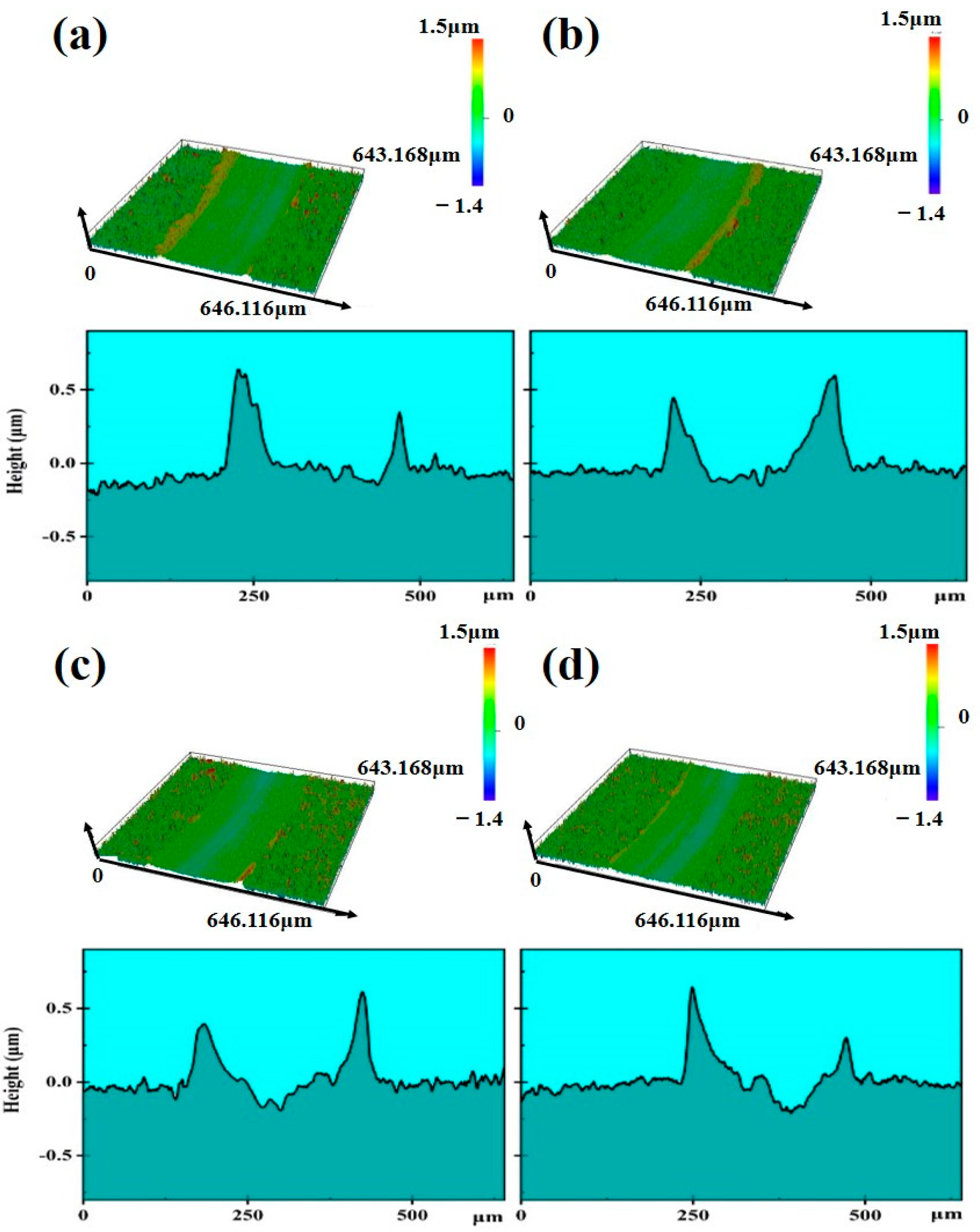
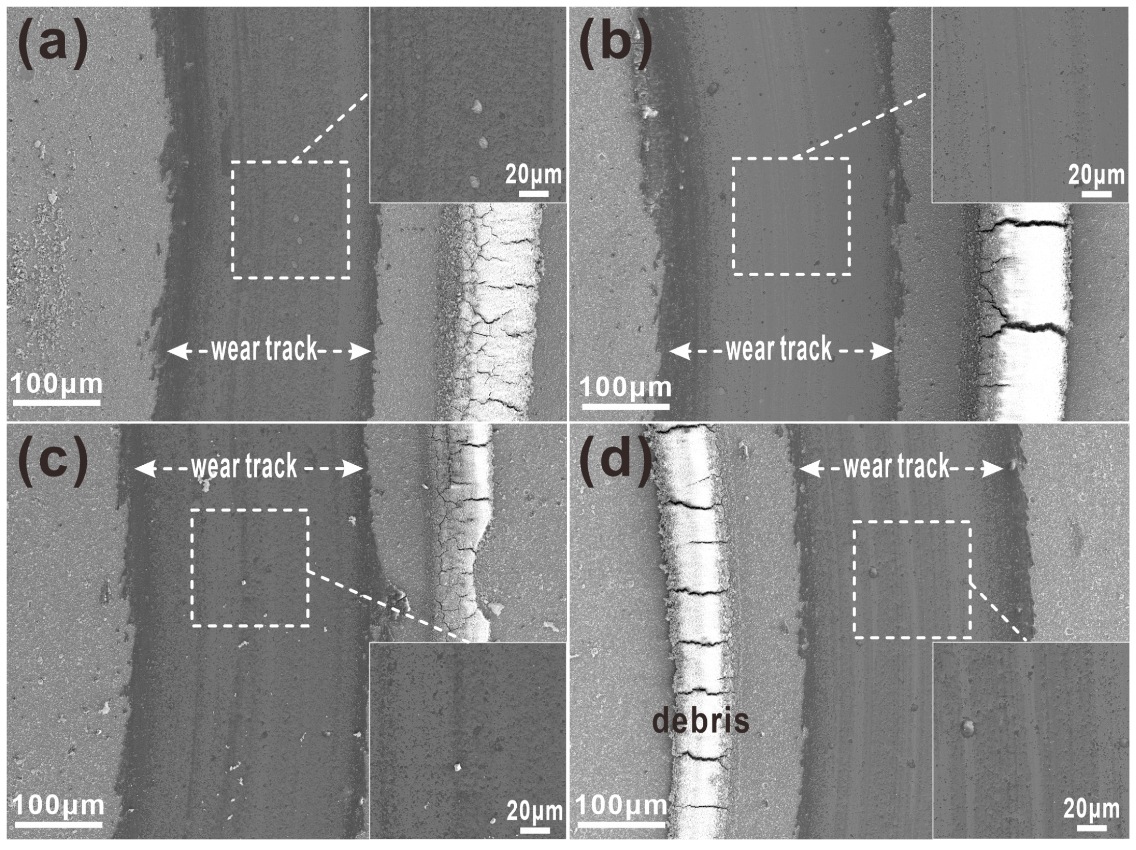
3.3. Tribological Properties

Room-temperature ball-on-disk friction and wear tests were conducted on AlCrMoN coatings deposited at different bias voltages, with friction coefficient curves shown in Figure 6a. During the initial stage, the friction coefficient increased sharply due to mechanical interlocking between the rough asperities of the Al2O3 counterball and the coating surface during first contact. As the test proceeded, the contact surfaces gradually smoothed, and oxidation occurred on the coating surface. The formation of lubricious oxide products (e.g., MoO3) facilitated friction reduction, leading to a steady-state stage [37]. During this stage, the average friction coefficients of the four coatings fluctuated between 0.4 and 0.6—specifically, 0.49 ± 0.05, 0.47 ± 0.02, 0.55 ± 0.01, and 0.53 ± 0.02—all lower than that of the AlCrN coatings (above 0.6), as shown in Figure 6b. The wear rates of the four coatings were (4.45 ± 0.16) × 10−8, (3.27 ± 0.10) × 10−8, (7.96 ± 0.27) × 10−8, and (5.52 ± 0.32) × 10−8 mm3/(N·m), respectively, showing a trend consistent with the average friction coefficients. Notably, the coating deposited at −100 V exhibited the best wear resistance. Although the −120 V coated sample possessed the highest hardness and finest grain size, excessive ion bombardment energy disrupted the microstructural integrity during deposition and introduced substantial residual tensile stress [38,39]. This stress promoted the nucleation and propagation of microcracks, which served as pathways for oxygen intrusion during wear. The intrusion generated oxide particles that exacerbated abrasive wear, thereby accelerating material spalling during the wear process and increasing the wear rates observed in the −120 V and −140 V coatings.
In contrast to conventional AlCrN nitride coatings (typically exhibiting wear rates of the order of 10−7 mm3/(N·m)), the AlCrMoN coating developed in this study achieved an extremely low wear rate of (3.27 ± 0.10) × 10−8 mm3/(N·m) under a −100 V bias voltage. However, when the bias voltage increased to −120 V, the wear rate of AlCrMoN rose sharply to (7.96 ± 0.27) × 10−8 mm3/(N·m). This phenomenon mirrored the hardness–brittleness trade-off commonly observed in AlCrN coatings, suggesting that residual-tensile stress-induced microcrack propagation governed the dominant failure mechanism.
Figure 7 presents the three-dimensional (3D) morphologies and cross-sectional profiles of the wear tracks for AlCrMoN coatings deposited at different bias voltages. From the 3D morphologies, varying degrees of wear debris accumulation could be observed at the edges of the wear tracks for all four coatings. The wear tracks of the −80 V and −100 V coatings were relatively smooth inside and predominantly green in color, while those of the −120 V and −140 V coatings exhibited light-blue plowing grooves. The cross-sectional profiles also revealed that the difference between the peaks and valleys of the wear tracks was larger for the −120 V and −140 V coatings compared with the −80 V and −100 V coatings, indicating a more severe degree of wear.
To further investigate the wear processes of the four coatings, SEM and EDS were used to observe the microtopography and elemental distribution of the wear tracks. Figure 8 shows the elemental line-scan results of AlCrMoN coatings. Bright white accumulations of Cr- and Al-rich oxide debris were evident on one side of the wear tracks (region B in the figure) for all four coatings. Sudden increases in Cr and O concentrations appeared at the two edges of the wear tracks (region A), indicating the enrichment of Cr oxides at these locations. Except for Figure 8b, random distributions of Cr oxides were also observed within the other three wear tracks, confirming the presence of oxide particles inside the worn regions. Additionally, no significant difference in Mo content was detected between the wear tracks and the coating surface, suggesting that the temperature at the friction interface during room-temperature testing remained far below the melting point of MoO3, thus preventing volatilization loss. MoO3, characterized by a low shear strength, provides a self-lubricating effect during friction, effectively reducing frictional resistance. Figure 9 presents the SEM morphologies of AlCrMoN wear tracks under different bias voltages. The presence of oxide particles was visually evident and particularly pronounced in the −120 V wear track. Distinct plowing grooves were observed in the −120 V and −140 V wear tracks, consistent with the 3D morphology observations described earlier.
Based on the above analysis, the wear process of AlCrMoN coatings during ball-on-disk friction tests could be summarized. In the initial stage, when the Al2O3 counterball first contacted the coating, the friction coefficient remained relatively low due to the coating’s inherent hardness and surface flatness. The microstructure of the coating remained mostly intact at this stage as the limited contact points between the coating asperities and the Al2O3 surface resulted in only shallow micro-scratches from minor particles on the counterball. These scratches had minimal impact on the coating’s overall performance, with the wear mechanism primarily characterized by mild abrasive wear. As friction proceeded, the number of contact points gradually increased and the friction coefficient began to rise, marking the transition into the running-in stage. The asperities on the AlCrMoN coating surface were gradually flattened, expanding the real contact area with the Al2O3 ball. This induced moderate plastic deformation in the coating to adapt to stress distribution during friction. In addition to abrasive wear, adhesive wear emerged at this stage: high local pressure and frictional forces at contact points caused material adhesion between the coating and counterball, which was subsequently torn off during relative motion, generating wear particles. After the running-in period, the friction coefficient tended to stabilize and entered the steady-state wear stage. A stable tribolayer formed on the coating surface consisting of coating material and oxidation products generated during friction. The dominant wear mechanisms were abrasive and oxidative wear: hard oxide particles continuously scratched the coating surface, causing material removal and plowing grooves. Conversely, the self-lubricating effect of Mo oxides (e.g., MoO3 with a low shear strength) mitigated further wear by reducing frictional resistance.

4. Conclusions

(1) AlCrMoN coatings prepared via AIP at different substrate bias voltages (−80 V, −100 V, −120 V, and −140 V) all exhibited a face-centered cubic (FCC) structure with columnar crystal growth. With an increasing bias voltage, the grain size of the coatings first decreased and then increased.
(2) The hardness and elastic modulus of AlCrMoN coatings showed a trend of first increasing and then decreasing with an increasing bias voltage, reaching a maximum hardness of 36.2 ± 1.33 GPa. All four coatings demonstrated strong adhesion to the cemented carbide substrate, with adhesion strengths exceeding 78 N.
(3) In room-temperature ball-on-disk friction and wear tests, the AlCrMoN coating deposited at −100 V exhibited the lowest average friction coefficient (0.42 ± 0.02) and wear rate ((3.27 ± 0.10) × 10−8 mm3/(N·m)). During the steady-state wear stage, the dominant wear mechanisms of AlCrMoN coatings were oxidative wear and abrasive wear.

Author Contributions

Conceptualization, methodology, and investigation, H.Z. (Haoqiang Zhang), C.W., H.S., and H.Z. (Hua Zhang); data curation, T.J. and H.Y.; writing—original draft preparation, J.L.; writing—review and editing, H.Z. (Haoqiang Zhang) and J.L.; visualization, J.L. and T.J.; supervision, X.W., L.X., and S.W.; funding acquisition, H.Z. (Haoqiang Zhang) and X.W. All authors have read and agreed to the published version of the manuscript.

Funding

This research was funded by the China Postdoctoral Science Foundation (2023M730979) and the Key Technology Research and Development Program of Henan Province (No. 232102231024).

Institutional Review Board Statement

Not applicable.

Informed Consent Statement

Not applicable.

Data Availability Statement

The raw/processed data required to reproduce these findings cannot be shared at this time as the data also forms part of an ongoing study.

Conflicts of Interest

Authors Haobin Sun and Hua Zhang were employed by the company Penglai Cemented Carbide Co., Ltd. The remaining authors declare that the research was conducted in the absence of any commercial or financial relationships that could be construed as a potential conflict of interest.

References

  1. Žemlička, R.; Alishahi, M.; Jílek, M.; Souček, P.; Daniel, J.; Kluson, J.; Bolvardi, H.; Lümkemann, A.; Vašina, P. Enhancing mechanical properties and cutting performance of industrially sputtered AlCrN coatings by inducing cathodic arc glow discharge. Surf. Coat. Technol. 2021, 422, 127563. [Google Scholar] [CrossRef]
  2. Ling, C.L.; Yajid, M.A.M.; Tamin, M.N.; Kamarudin, M.; Taib, M.A.A.; Nosbi, N.; Wan Ali, W.F.F. Effect of substrate roughness and PVD deposition temperatures on hardness and wear performance of AlCrN-coated WC-Co. Surf. Coat. Technol. 2022, 436, 128304. [Google Scholar] [CrossRef]
  3. Zhang, H.; Xu, Y.X.; Chen, Y.; Peng, B.; Wei, T.; Zhang, F.; Li, H.; Wang, Q. Temperature-dependent oxidation behavior of arc evaporated Al–Ti–B–N coatings. Corros. Sci. 2022, 203, 110347. [Google Scholar] [CrossRef]
  4. Zhou, S.; Kuang, T.; Qiu, Z.; Zeng, D.; Zhou, K. Microstructural origins of high hardness and toughness in cathodic arc evaporated Cr-Al-N coatings. Appl. Surf. Sci. 2019, 493, 1067–1073. [Google Scholar] [CrossRef]
  5. Tritremmel, C.; Daniel, R.; Lechthaler, R.; Polcik, P.; Mitterer, C. Influence of Al and Si content on structure and mechanical properties of arc evaporated Al-Cr-Si-N thin films. Thin Solid Films 2023, 534, 403–409. [Google Scholar] [CrossRef]
  6. Mato, S.; Alcalá, G.; Brizuela, M.; Galindo, R.E.; Pérez, F.J.; Sánchez-López, J.C. Long-term high temperature oxidation of CrAl(Y)N coatings in steam atmosphere. Corros. Sci. 2014, 80, 453–460. [Google Scholar] [CrossRef]
  7. Kelly, P.J.; Hisek, J.; Zhou, Y.; Pilkington, R.D.; Arnell, R.D. Advanced coatings through pulsed magnetron sputtering. Surf. Eng. 2004, 20, 157–162. [Google Scholar] [CrossRef]
  8. Polcar, T.; Cavaleiro, A. High-temperature tribological properties of CrAlN, CrAlSiN and AlCrSiN coatings. Surf. Coat. Technol. 2011, 206, 1244–1251. [Google Scholar] [CrossRef]
  9. Rovere, F.; Music, D.; Schneider, J.M.; Mayrhofer, P.H. Experimental and computational study on the effect of yttrium on the phase stability of sputtered Cr-Al-Y-N hard coatings. Acta Mater. 2010, 58, 2708–2715. [Google Scholar] [CrossRef]
  10. Yan, C.; Yu, Y.; Mei, F.; Gao, J.; Lin, X.; Lin, J. A Si-Nb co-alloyed AlCrN coating with good mechanical properties, excellent thermal stability and resistance to high temperature oxidation. Surf. Coat. Technol. 2024, 484, 130825. [Google Scholar] [CrossRef]
  11. Wolfgang, T.; David, K.; Dominic, S.; Michael, P.; Christian, S.; Metin, T. Investigation of the influence of the vanadium content on the high temperature tribo-mechanical properties of DC magnetron sputtered AlCrVN thin films. Surf. Coat. Technol. 2017, 328, 172–181. [Google Scholar] [CrossRef]
  12. Veprek, S.; Veprek-Heijman, M.G.J.; Karvankova, P.; Prochazka, J. Different approaches to superhard coatings and nanocomposites. Thin Solid Films 2005, 476, 1–29. [Google Scholar] [CrossRef]
  13. Devarajan, D.K.; Rangasamy, B.; Amirtharaj, M.K.K. State-of-the-art developments in advanced hard ceramic coatings using PVD techniques for high-temperature tribological applications. Ceramics 2023, 6, 301–329. [Google Scholar] [CrossRef]
  14. Lukaszkowicz, K.; Sondor, J.; Paradecka, A.; Pawlyta, M.; Chmiela, B.; Pancielejko, M.; Szczucka-Lasota, B.; Węgrzyn, T.; Tański, T. Structure and tribological properties of AlCrN+CrCN coating. Coatings 2020, 10, 1084. [Google Scholar] [CrossRef]
  15. Wu, W.; Chen, W.; Yang, S.; Lin, Y.; Zhang, S.; Cho, T.Y.; Lee, G.H.; Kwon, S.C. Design of AlCrSiN multilayers and nanocomposite coating for HSS cutting tools. Appl. Surf. Sci. 2015, 351, 803–810. [Google Scholar] [CrossRef]
  16. Kim, Y.J.; Byun, T.J.; Han, J.G. Bilayer period dependence of CrN/CrAlN nanoscale multilayer thin films. Superlattices Microstruct. 2009, 45, 73–79. [Google Scholar] [CrossRef]
  17. Bobzin, K.; Brögelmann, T.; Kruppe, N.C.; Arghavani, M. Investigations on mechanical and tribological behavior of DCMS/HPPMS CrN and (Cr, Al)N hard coatings using nanoscratch technique. Adv. Eng. Mater. 2017, 19, 1600632. [Google Scholar] [CrossRef]
  18. Wang, Y.; Ji, Y. Influence of Mo Doping on the Microstructure, Friction, and Wear Properties of CrAlN Films. J. Mater. Eng. Perform. 2021, 30, 1938–1944. [Google Scholar] [CrossRef]
  19. Lou, B.; Wang, Y. Effects of Mo content on the micro-structure and tribological properties of CrMoAlN films. Acta Metall. Sin. 2016, 52, 727–733. [Google Scholar] [CrossRef]
  20. Iram, S.; Cai, F.; Wang, J.; Zhang, J.; Liang, J.; Ahmad, F.; Zhang, S. Effect of addition of Mo or V on the structure and cutting performance of AlCrN-based coatings. Coatings 2020, 10, 298. [Google Scholar] [CrossRef]
  21. Shi, J.; Chen, Y.; Liu, H.; Kang, J.; Li, X.; Zhang, L.; Xian, G.; Du, H. Effect of Mo and C Contents on the Crystal Structure and Properties of AlCrN Films. China Surf. Eng. 2022, 35, 286–296. [Google Scholar] [CrossRef]
  22. Glatz, S.A.; Koller, C.M.; Bolvardi, H.; Kolozsvári, S.; Riedl, H.; Mayrhofer, P.H. Influence of Mo on the structure and the tribomechanical properties of arc evaporated Ti-Al-N. Surf. Coat. Technol. 2017, 311, 330–336. [Google Scholar] [CrossRef]
  23. Klimashin, F.F.; Mayrhofer, P.H. Ab initio-guided development of super-hard Mo-Al-Cr-N coatings. Scr. Mater. 2017, 140, 27–30. [Google Scholar] [CrossRef]
  24. Di, Y.; Zhang, P.; Cai, Z.; Yang, Z.; Li, Q.; Shen, W. Effect of Mo content on the structural and mechanical properties of CrMoN/MoS2 composite coatings. Rare Met. Mater. Eng. 2014, 43, 264–268. [Google Scholar] [CrossRef]
  25. Jaf, Z.N.; Jiang, Z.T.; Miran, H.A.; Altarawneh, M.; Veder, J.P.; Minakshi, M.; Zhou, Z.F.; Lim, H.N.; Huang, N.M.; Dlugogorski, B.Z. Physico-chemical properties of CrMoN coatings-combined experimental and computational studies. Thin Solid Film. 2020, 693, 137671. [Google Scholar] [CrossRef]
  26. Chen, Y.; Xu, Y.X.; Zhang, H.; Wang, Q.; Wei, T.; Zhang, F.; Kim, K.H. Improving high-temperature wear resistance of arc-evaporated AlCrN coatings by Mo alloying. Surf. Coat. Technol. 2023, 456, 129253. [Google Scholar] [CrossRef]
  27. Iram, S.; Wang, J.; Cai, F.; Zhang, J.; Ahmad, F.; Liang, J.; Zhang, S. Effect of bilayer number on mechanical and wear behaviors of the AlCrN/AlCrMoN coatings by AIP method. Surf. Eng. 2021, 37, 536–544. [Google Scholar] [CrossRef]
  28. Wang, Z.; Zhou, S.; Ma, G.; Dong, Y.; Zhang, X.; Liu, Y.; Wang, Z.; Wang, A. Achieving ultrastrong-tough CrAlN coatings with low friction coefficient by Y incorporating. Ceram. Int. 2024, 50, 23621–23633. [Google Scholar] [CrossRef]
  29. Zhao, Y.; He, Y.; Chen, Q.; Gong, Z.; Wang, Z.; Wang, K.; Shi, M.; Chen, R. Effect of substrate bias voltage on structure and corrosion resistance of AlCrN coatings prepared by multi-arc ion plating. Int. J. Electrochem. Sci. 2021, 16, 210938. [Google Scholar] [CrossRef]
  30. Lomello, F.; Sanchette, F.; Schuster, F.; Tabarant, M.; Billard, A. Influence of bias voltage on properties of AlCrN coatings prepared by cathodic arc deposition. Surf. Coat. Technol. 2013, 224, 77–81. [Google Scholar] [CrossRef]
  31. Li, Z.; Wang, Y.; Cheng, X.; Zeng, Z.; Li, J.; Lu, X.; Wang, L.; Xue, Q. Continuously growing ultrathick CrN coating to achieve high load-bearing capacity and good tribological property. ACS Appl. Mater. Interfaces 2018, 10, 2965–2975. [Google Scholar] [CrossRef] [PubMed]
  32. Bemporad, E.; Sebastiani, M.; Pecchio, C.; Rossi, S.D. High thickness Ti/TiN multilayer thin coatings for wear resistant applications. Surf. Coat. Technol. 2006, 201, 2155–2165. [Google Scholar] [CrossRef]
  33. Smilgies, D.M. Scherrer Grain-size analysis adapted to grazing-incidence scattering with area detectors. J. Appl. Crystallogr. 2009, 42, 1030–1034. [Google Scholar] [CrossRef] [PubMed]
  34. Oliver, W.C.; Pharr, G.M. An improved technique for determining hardness and elastic modulus using load and displacement sensing indentation experiments. J. Mater. Res. 1992, 7, 1564–1583. [Google Scholar] [CrossRef]
  35. Zhang, S.; Sun, D.; Fu, Y.; Du, H. Effect of sputtering target power on microstructure and mechanical properties of nanocomposite nc-TiN/a-SiNx thin films. Thin Solid Films 2004, 447–448, 462–467. [Google Scholar] [CrossRef]
  36. Wan, X.S.; Zhao, S.S.; Yang, Y.; Gong, J.; Sun, C. Effects of nitrogen pressure and pulse bias voltage on the properties of Cr-N coatings deposited by arc ion plating. Surf. Coat. Technol. 2010, 204, 1800–1810. [Google Scholar] [CrossRef]
  37. Liu, A.; Deng, J.; Cui, H.; Chen, Y.; Zhao, J. Friction and wear properties of TiN, T99iAlN, AlTiN and CrAlN PVD nitride coatings. Int. J. Refract. Met. Hard Mater. 2012, 31, 82–88. [Google Scholar] [CrossRef]
  38. Tang, J.F.; Lin, C.Y.; Yang, F.C.; Chang, C.L. Influence of nitrogen content and bias voltage on residual stress and the tribological and mechanical properties of CrAlN films. Coatings 2020, 10, 546. [Google Scholar] [CrossRef]
  39. Kong, Q.; Ji, L.; Li, H.; Liu, X.; Wang, Y.; Chen, J.; Zhou, H. Influence of substrate bias voltage on the microstructure and residual stress of CrN films deposited by medium frequency magnetron sputtering. Mater. Sci. Eng. B 2011, 176, 850–854. [Google Scholar] [CrossRef]
Figure 1. SEM surface morphologies of AlCrMoN coatings deposited at (a) −80 V, (b) −100 V, (c) −120 V, (d) −140 V, and (e) corresponding surface particle statistics.
Coatings 15 00673 g001
Figure 2. SEM cross-sectional morphologies of AlCrMoN coatings deposited at (a) −80 V, (b) −100 V, (c) −120 V, and (d) −140 V.
Coatings 15 00673 g002
Figure 3. (a) GIXRD patterns and (b) FWHM of (111) peak of (Cr, Al)N phase for AlCrMoN coatings deposited at different bias voltages.
Coatings 15 00673 g003
Figure 4. Hardness (H), elastic modulus (E), and H3/E2 values of AlCrMoN coatings deposited at different bias voltages.
Coatings 15 00673 g004
Figure 5. Scratch morphologies of AlCrMoN coatings deposited at different bias voltages.
Coatings 15 00673 g005
Figure 6. (a) Coefficients of friction and (b) average COF and wear rates of AlCrMoN coatings deposited at different bias voltages.
Coatings 15 00673 g006
Figure 7. Three-dimensional morphologies and cross-sectional profiles of the wear tracks of AlCrMoN coatings deposited at (a) −80 V, (b) −100 V, (c) −120 V, and (d) −140 V.
Coatings 15 00673 g007
Figure 8. Elemental line-scan results of AlCrMoN coatings deposited at (a) −80 V, (b) −100 V, (c) −120 V, and (d) −140 V.
Coatings 15 00673 g008
Figure 9. SEM morphologies of the wear tracks of AlCrMoN coatings deposited at (a) −80 V, (b) −100 V, (c) −120 V, and (d) −140 V.
Coatings 15 00673 g009
Table 1. Chemical composition of AlCrMoN coatings deposited at different bias voltages.
CoatingBias, VElemental Concentration, at%Al/CrMo/(Al + Cr + Mo)
AlCrMoN
AlCrMoN−8026.222.67.443.81.160.13
−10026.823.17.442.71.160.13
−12026.523.47.342.81.130.13
−14025.923.07.843.31.130.14
Disclaimer/Publisher’s Note: The statements, opinions and data contained in all publications are solely those of the individual author(s) and contributor(s) and not of MDPI and/or the editor(s). MDPI and/or the editor(s) disclaim responsibility for any injury to people or property resulting from any ideas, methods, instructions or products referred to in the content.

