Article

Corrosion and Wear Behavior of 17-4PH Stainless Steel Manufactured by Selective Laser Melting and Bulk Material After Solution Treatment

1
Department of Optoelectronics and Materials Technology, National Taiwan Ocean University, Keelung 202, Taiwan
2
Department of Mechanical Engineering, Lunghwa University of Science and Technology, Taoyuan 333, Taiwan
3
Department of Mechanical and Computer-Aided Engineering, Army Academy, Taoyuan 320, Taiwan
4
Graduate Institute of Manufacturing Technology, National Taipei University of Technology, Taipei 106, Taiwan
*
Authors to whom correspondence should be addressed.
Coatings 2025, 15(6), 649; https://doi.org/10.3390/coatings15060649
Submission received: 30 April 2025 / Revised: 23 May 2025 / Accepted: 25 May 2025 / Published: 28 May 2025
(This article belongs to the Special Issue Anti-corrosion Coatings of Metals and Alloys—New Perspectives)

Abstract

:
This study aims to investigate the wear and corrosion–wear behavior of 17-4PH stainless steel specimens, both fabricated via Selective Laser Melting (SLM) and conventional bulk material, after undergoing Solution Treatment (S.T.) in a seawater medium. Microstructural observations indicated that solution treatment contributed to a more uniform distribution of martensitic structures on the sample surface. Moreover, the solution-treated specimens exhibited improved microstructural uniformity and structural stability. SLM specimens exhibit the elimination of fine particles and scanning track traces. Based on the results of dynamic polarization tests, SLM specimens demonstrate superior corrosion resistance. However, in corrosion–wear conditions, the bulk material outperforms the SLM specimens, primarily due to the presence of pores in the latter, which are detrimental under such environments. XPS analysis of the passive film structure indicates that the passive layer is mainly composed of FeO, Cr2O3, and NiO, with the inner layer predominantly consisting of chromium oxide. The Cr2O3 layer, formed by the reaction between chromium and oxygen, significantly enhances the corrosion resistance of the material due to its extremely low chemical reactivity and high stability.

Graphical Abstract

1. Introduction

17-4PH stainless steel is a typical precipitation-hardened martensitic stainless steel known for its high strength, excellent corrosion resistance, and oxidation resistance, and it has been widely utilized in the field of Additive Manufacturing (AM). Its alloy composition can exhibit a combination of ferrite, austenite, martensite, and precipitation-hardened phases [1]. Due to differences in the morphology and composition of the passive film, solution treatment, aging, and manufacturing techniques, the material’s microstructure varies, resulting in changes in corrosion resistance depending on the composition and processing parameters [2]. Among various additive manufacturing technologies, Selective Laser Melting (SLM), classified under Laser Powder Bed Fusion (L-PBF), is widely used [3]. SLM employs a high-energy density laser beam to selectively melt metal powders layer by layer, followed by rapid solidification to form three-dimensional components [4]. This process allows for precise control over the melting of materials, enabling the production of complex geometries such as internal channels, lattice structures, and topology-optimized designs, which are difficult or impossible to achieve through traditional manufacturing [5]. Additionally, SLM improves material utilization as unused powders can be recycled [6].
The core of SLM lies in slicing a 3D model into thin layers, uniformly spreading metal powder on a platform, and selectively melting it based on each layer’s geometry [7]. The melted regions solidify rapidly, building a complete part layer by layer [8]. This technology is extensively used for fabricating highly complex and customized metal parts, particularly in precision industries [9]. However, the rapid scanning and cooling associated with SLM lead to significant thermal stress and microstructural differences compared to conventional methods. Minor variations in processing parameters such as laser energy density, scan speed, powder characteristics, and melt pool dynamics can substantially affect the final properties [10,11].
Despite its advantages, 17-4PH stainless steel exhibits poor ductility and is prone to hydrogen embrittlement and stress corrosion cracking. Moreover, the SLM process often introduces porosity defects, limiting its application in certain fields [12]. Zhao [13] suggested that these deficiencies could be mitigated through solution and aging treatments, which enhance corrosion resistance by promoting the uniform distribution of corrosion-resistant elements like chromium and nickel while simultaneously improving ductility and toughness [14]. Tavares [15] further noted that such heat treatments make 17-4PH stainless steel suitable for demanding environments, including marine engineering, aerospace engine components, valve parts, and power generation systems.
The properties of 17-4PH stainless steel during solution treatment are significantly affected by the solution temperature. High temperatures effectively relieve internal residual stresses and promote recrystallization and microstructural reconstruction [16]. Nezhadfar et al. [17] reported that heat treatment facilitates the uniform dissolution of alloying elements into the matrix and redistributes the secondary phases, thereby enhancing the mechanical properties and corrosion resistance. Post heat treatment, 17-4PH stainless steel exhibits a homogeneous martensitic microstructure with significantly improved hardness and mechanical strength. According to the study by Lou et al. [18], 17-4PH stainless steel undergoes significant microstructural evolution after aging heat treatment. The precipitation of NbC and Cu particles plays a crucial role in strengthening the material. Specifically, NbC forms fine and stable precipitates within the matrix, enhancing the material’s strength and resistance to plastic deformation. Additionally, nano-sized Cu precipitates distribute uniformly during the aging process, further reinforcing the martensitic matrix and improving hardness and wear resistance. while Cu precipitates contribute to precipitation hardening, further boosting mechanical strength. Moreover, solution treatment not only enhances the mechanical properties but also effectively eliminates internal residual stresses, which is crucial for improving the overall performance of 17-4PH stainless steel. The removal of residual stresses prevents stress corrosion cracking, thereby extending the service life of components [19]. A homogenized microstructure also enhances corrosion resistance, ensuring better long-term stability in harsh environments. The commonly recommended solution treatment temperature for 17-4PH stainless steel ranges from 1000 °C to 1060 °C. Shen et al. [20] reported that solution treatment is a commonly employed method to enhance material properties due to its significant influence on the austenitization process. Their study demonstrated that, under identical aging conditions, variations in solution treatment parameters can significantly affect the mechanical properties and corrosion resistance of martensitic stainless steels.
In the context of SLM, solution treatment is a widely adopted post-processing method that significantly improves the microstructure and mechanical properties of additively manufactured metal parts [21]. Due to rapid melting and cooling inherent in the SLM process, parts often suffer from high residual stresses, porosity defects, and microstructural inhomogeneities [22]. Solution treatment homogenizes the microstructure, reduces porosity, and releases residual stresses, leading to improved mechanical performance [23]. Cabezon et al. [24] demonstrated that solution treatment refines the grain structure, reduces porosity, and lowers the corrosion current density of parts immersed in phosphate-buffered saline (PBS) solutions, thus enhancing corrosion resistance.
Furthermore, solution treatment addresses defects such as pores and lack-of-fusion regions typically formed during SLM, resulting in smoother surfaces and higher localized strength [25].
Travares et al. [26] reported that in a 3.5% NaCl solution, stainless steels with high sulfur content exhibit a higher degree of sensitization, primarily due to the increased presence of manganese sulfide (MnS) inclusions. This indicates inferior resistance to chloride-induced corrosion. MnS particles act as initiation sites for pitting, promoting local acidification and leading to passive film breakdown, which further accelerates the development of intergranular corrosion. Fang et al. [27] confirmed that 17-4PH stainless steel produced by SLM exhibits outstanding mechanical properties and corrosion resistance in chloride-containing acidic solutions, marine environments, and industrial conditions. This improvement is attributed to the rapid cooling and solidification processes during SLM, which suppress temperature gradients, shorten solidification times, enhance the uniform distribution of NbC oxides, and inhibit the formation of MnS inclusions [28].
In addition to corrosion, wear is another critical factor contributing to material degradation. Wear refers to mechanical damage caused by friction and relative motion between two contacting surfaces. Corrosion–wear describes the synergistic degradation of materials subjected to both mechanical wear and corrosive environments. During the corrosion–wear process, the protective oxide layer is continuously removed by mechanical action, exposing fresh metal surfaces and accelerating corrosion processes.
Lin et al. [29] studied the corrosion and wear behaviors of high-velocity oxygen fuel (HVOF)-sprayed Fe-based amorphous coatings in seawater environments. Dynamic polarization curves and friction coefficient tests revealed that the passive films formed under pure corrosion conditions offered protection; however, under corrosion–wear conditions, the passive films were repeatedly removed by friction, leading to enhanced material degradation. Esfandiari et al. [30] further demonstrated that during corrosion–wear, the continuous damage to the passive layer sustains a high corrosion current, significantly accelerating material degradation.
Surface modification treatments, such as plasma treatments in 3.5% NaCl solutions, have been shown to enhance the corrosion–wear resistance of 17-4PH stainless steel. Samples subjected to both surface modification and heat treatment exhibited superior corrosion–wear resistance, primarily due to the formation of thick surface compound layers [31].
In this study, the corrosion and corrosion–wear behaviors of 17-4PH stainless steel were systematically investigated. Comparative analyses were performed between SLM-fabricated specimens and conventionally manufactured bulk materials after solution treatment. Through microstructural and surface morphology characterizations, the effects of different manufacturing processes on the performance of the materials were explored.

2. Experimental

2.1. 17-4PH Stainless Steel Bulk Samples and Selective Laser Melting (SLM) Parameters

In this study, specimens were fabricated using a metal 3D printer (Model: TSLM-180) manufactured by TeraSolar Energy Materials Corp. (Keelung City, Taiwan), employing Selective Laser Melting (SLM) technology. The printing parameters were as follows: laser power of 200 W, fiber laser with a wavelength of 1064 nm, laser spot diameter ranging from 10 to 100 μm, powder layer thickness of 0.03 mm, scanning speed of 0.8 m/s, and argon gas as the protective atmosphere to prevent high-temperature oxidation. The model building rate ranged from 1 to 30 cm3/h, and the printing direction was from left to right and bottom to top in a layer-by-layer manner. The printed specimens had a hollow cylindrical geometry with dimensions of 20 mm in diameter, 13 mm in inner diameter, and 8 mm in thickness. Additionally, to compare the behavior of conventionally manufactured materials, bulk 17-4PH stainless steel produced by traditional processes was machined into the same dimensions (20 mm diameter, 13 mm inner diameter, 8 mm thickness) and subjected to the same solution heat treatment (1040 °C for 1 h followed by water quenching). This allowed for a systematic comparison of the microstructure, corrosion properties, and wear behavior between the two fabrication methods.

2.2. Solution Treatment Conditions

The specimens were first heated to 1040 °C at a rate of 10 °C per minute and held at this temperature (±5 °C) for 1 h to ensure sufficient high-temperature dissolution. This temperature condition allows the precipitation of copper (Cu) and carbides within the matrix of 17-4PH stainless steel, which contributes to the improvement of the material’s mechanical properties and corrosion resistance, thereby enhancing its performance in subsequent applications [17,18]. Afterwards, the specimens were air-cooled to room temperature. The rapid cooling helps to prevent the formation of carbides or other precipitates, maintaining the stability and homogeneity of the solid solution structure, thus achieving an optimal microstructural quality.

2.3. Electrochemical Analysis, Corrosion, and Corrosive Wear Testing

Electrochemical polarization testing was conducted using a potentiostat (Zahner Zennium-E 41100) The equipment was manufactured by Zahner-Elektrik GmbH & Co. KG, located in Kronach-Gundelsdorf, Bavaria, Germany, under a conventional three-electrode configuration. A saturated calomel electrode (SCE) served as the reference electrode, platinum (Pt) was employed as the counter electrode, and the specimen under investigation was used as the working electrode.
For the tribocorrosion testing, a rotary tribocorrosion testing apparatus was coupled with the potentiostat. An alumina ceramic block (21 × 21 × 21 mm) was used as the counter body in a block-on-ring configuration. The applied normal load was set to 29.4 N, and the rotation speed was maintained at 200 RPM. During the tests, polarization curves under both corrosion and tribocorrosion conditions were recorded [29]. The potential sweep range for both corrosion and tribocorrosion measurements was from −1.0 V to +1.0 V, with a scan rate of 0.5 mV/s.
Additionally, open-circuit potential (OCP) measurements were performed on 17-4PH stainless steel under dynamic conditions for a duration of 40 min. For the potentiostatic corrosion tests, the applied potentials were selected based on regions identified in the dynamic polarization curves. These regions were categorized as the active region (OCP and −500 mVSCE), passive region (−300 mVSCE and +100 mVSCE), and transpassive region (+500 mVSCE). Each condition was maintained for 40 min while the current density was monitored.
All experiments were conducted using natural seawater collected from Keelung, Taiwan. The seawater conditions were as follows: temperature ranged from 25.5 to 26.5 °C; dissolved oxygen content ranged from 4.2 to 8.8 mg/L; chloride ion concentration varied from 13,500 to 24,100 ppm; pH ranged between 7.20 and 8.54; and electrical conductivity ranged from 38.2 to 52.3 mmho/cm; and salinity ranged from 31 to 34 PSU.

2.4. XRD and DSC Analytical Parameters

During specimen preparation, samples were precisely cut into flat plates of 5 × 5 × 0.5 mm using a diamond blade cutter. Post-cutting, the specimens were ground to remove burrs generated during sectioning, ensuring a smooth and uniform surface. Subsequently, the specimens were immersed in ethanol and subjected to ultrasonic agitation for 2 min to eliminate residual surface contaminants. After cleaning, the samples were dried in an oven to ensure complete removal of moisture.
The crystalline structure was analyzed using a Bruker D2 Phaser X-ray diffractometer (XRD), equipped with a Cu Kα radiation source (λ = 1.54 Å) and a maximum power capacity of 12 kW. the instrument was operated at an accelerating voltage of 30 kV and a current of 10–30 mA. Scanning was performed with a step size of 0.05° and a scan rate of 0.5°/min over a 2θ range of 20° to 80°.
Differential scanning calorimetry (DSC) was carried out with stringent control of sample mass between 2 and 6 mg to ensure high measurement accuracy and repeatability. A Netzsch 404 F3 DSC system was used, employing high-temperature-resistant alumina crucibles to withstand thermal loading without interfering with the sample. During the test, the specimens were heated from room temperature to 1100 °C at a constant heating rate of 10 °C/min under a high-purity argon atmosphere. The argon flow rate was maintained at 50 mL/min throughout the analysis.

2.5. Quantitative Analysis and Calculation of Tribocorrosion

In tribocorrosion studies, analyzing the weight loss of the specimen enables the differentiation between material degradation caused by corrosion and that caused by mechanical wear. Such analysis is essential for the development of effective protection strategies. Subsequently, the synergistic interaction between corrosion and wear must be considered. In this context, Lee et al. [29] proposed the following equation to quantify this interaction:
W t o t a l = W c o r r + W w e a r + Δ W
where total represents the total weight loss after tribocorrosion testing; Wcorr denotes the weight loss under pure corrosion conditions; and Wwear corresponds to the weight loss due to mechanical wear in a wet sliding environment (using reverse osmosis (RO) water). The synergistic weight loss, denoted by ΔW, reflects the material degradation resulting from the interaction between corrosion and wear and can be further expressed as follows:
Δ W = Δ W c o r r + Δ W w e a r
ΔWcorr can be determined from the corrosion rate equation, as shown below:
Δ W c o r r = M n F Δ i c o r r S · t
M denotes the atomic mass of the iron-based material (g); n is the number of electrons transferred; F represents the Faraday constant; Δicorr is the corrosion current density (mA/cm2); and t is the exposure time (s). By integrating the aforementioned parameters, the following expression is obtained:
Δ W w e a r = W t o t a l W w e a r W c o r r Δ W c o r r

3. Results

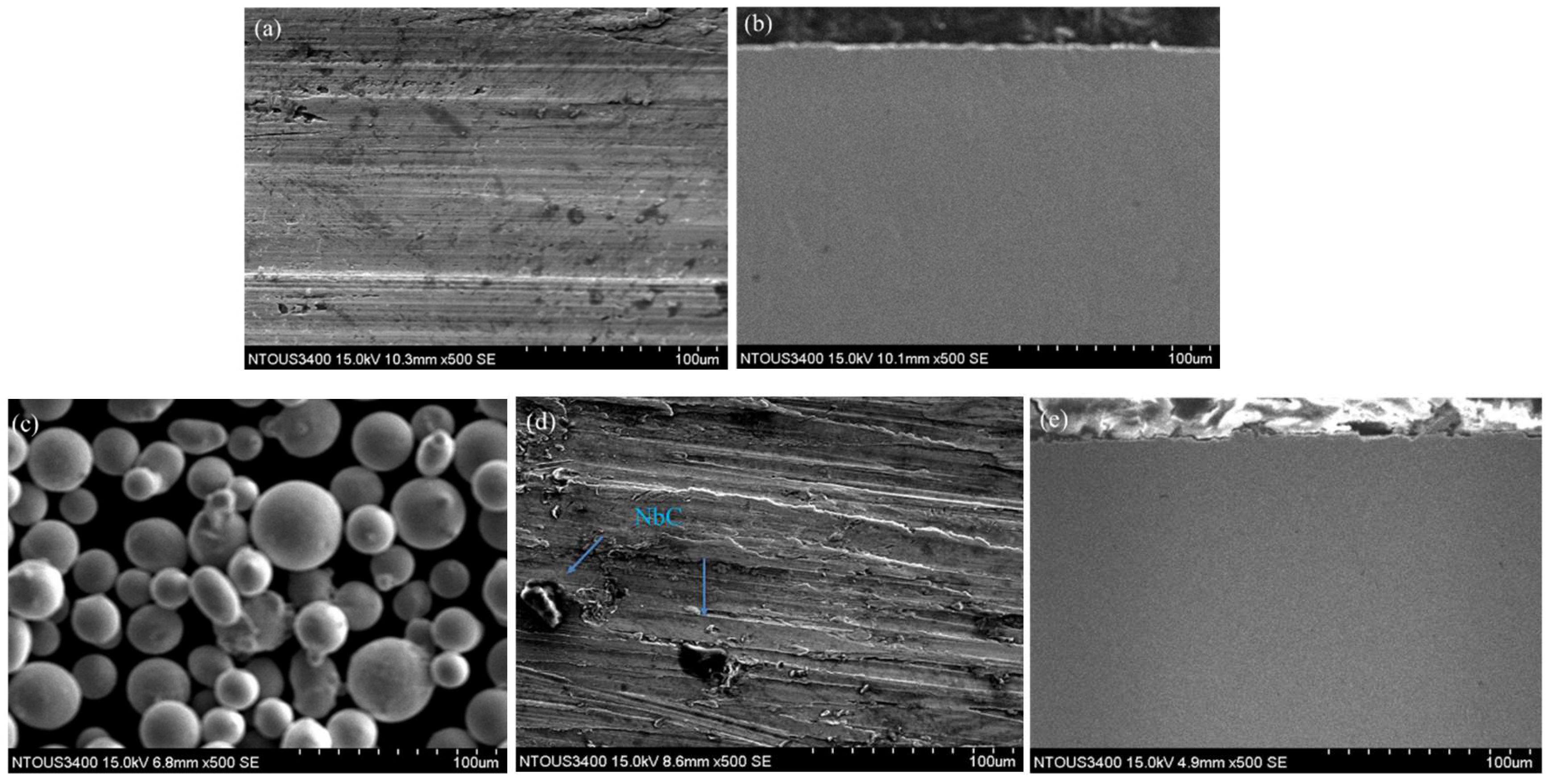
3.1. Observation of the As-Built Microstructure

Surface and cross-sectional morphologies of the conventionally processed (hot-rolled) bulk specimen after solution treatment. were examined via scanning electron microscopy (SEM), as shown in Figure 1a,b. Evident machining marks were observed on the surface, which originated from the cutting process. Figure 1c displays the 17-4PH stainless steel powders used in the preparation of the SLM specimens. The powder particles exhibited a uniform micron-scale distribution with sizes ranging approximately from 15 μm to 45 μm.
Figure 1d,e present the microstructural features of the surface and cross-section of the SLM specimens after solution treatment. Dark, block-like features were observed on the surface of the S.T. (SLM) sample. Energy-dispersive spectroscopy (EDS) analysis revealed that these features consisted of 52.15 at% Nb and 47.85 at% C, indicating the formation of niobium carbide (NbC). The dispersion of NbC precipitates contributes to precipitation strengthening. The finer and more uniformly distributed the particles, the greater the strengthening effect, which significantly enhances the tensile strength and wear resistance of the material [10]. To further analyze the microstructural composition, EDS analysis was performed on the surface regions of all specimens, and the results are summarized below. The typical chemical composition of 17-4PH stainless steel includes approximately 15–17.5 at% chromium (Cr), 3–5 at% nickel (Ni), and 3–5 at% copper (Cu). Its hardness significantly increases after appropriate solution treatment and aging, as shown in Table 1.
Optical microscopy revealed that with increasing the solution treatment temperature, the formation of martensite occurred through an austenite-to-martensite transformation. This transformation involves heating the material above the austenitizing temperature to form austenite, followed by rapid cooling below the martensite start temperature (Ms), leading to a diffusionless phase transformation into martensite [4]. The observed microstructures mainly consisted of martensite, accompanied by minor carbides.
Figure 2a,b show that the surfaces of both the bulk and SLM specimens after solution treatment exhibited a uniform distribution of fine martensitic grains. During the solution treatment, precipitation of carbides was observed. which plays a critical role in subsequent age-hardening by providing nucleation sites. This contributes to the enhancement of strength and hardness and facilitates the reprecipitation of columnar grains [5].
Moreover, the solution-treated SLM specimens not only exhibited a more homogeneous microstructure but also showed a substantial reduction or elimination of melt pool boundaries and scan track features. During the SLM process, a laser beam selectively melts the metal powder layer by layer followed by rapid solidification. However, due to uneven energy distribution, incomplete melting and poor bonding between adjacent melt pools may result in the formation of micropores in the final structure. After solution treatment, characteristic SLM-induced features such as melt pool boundaries, scan lines, and stacking artifacts were significantly reduced or partially eliminated [21].

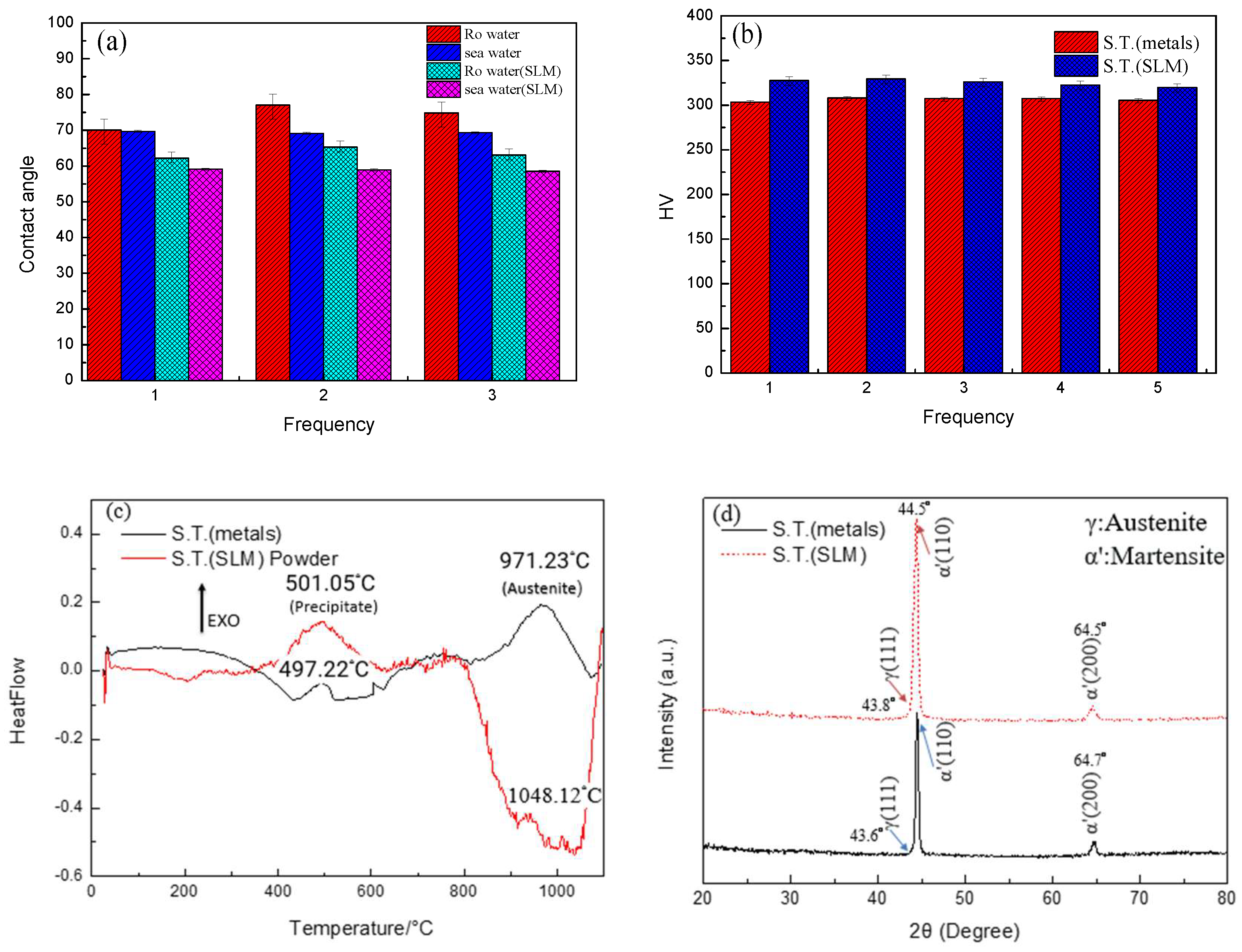
3.2. Hardness Measurement, XRD, and DSC Analysis Results

In the contact angle measurements, both reverse osmosis (RO) water and natural seawater were used to evaluate the wettability of the specimens, as shown in Figure 3a. According to the definition of contact angle, a value greater than 90° indicates hydrophobic behavior. The average contact angles of the bulk specimen were 73.97° in RO water and 69.37° in seawater, while the SLM specimen exhibited lower contact angles of 63.51° and 58.87°, respectively, indicating enhanced hydrophilicity. This phenomenon is attributed to the presence of micropores inherent to the SLM process.
As suggested by Lin et al. [14], surface roughness enhances the intrinsic wettability characteristics of materials, amplifying either hydrophilic or hydrophobic behavior. Thus, the increased surface roughness of SLM specimens, caused by microporous structures, facilitates water infiltration and adhesion, promoting greater hydrophilicity. Additionally, contact angles measured in seawater were consistently lower than those in RO water, due to the higher viscosity and dissolved salt content of seawater, which influence surface wetting behavior and enhance adhesion. Both types of specimens exhibited contact angles below 90° in seawater, indicating higher wettability, which in turn may lead to decreased corrosion resistance. The porosity resulting from the SLM process plays a critical role in affecting both the contact angle and the material’s corrosion resistance.
Vickers hardness tests revealed that the average hardness values of the solution-treated bulk and SLM specimens were 306.30 HV and 325.08 HV, respectively, as illustrated in Figure 3b. The higher hardness in the SLM specimen is primarily attributed to the rapid solidification associated with the SLM process, which produces finer grain structures. According to the Hall–Petch relationship [6], a reduction in grain size increases grain boundary density, thereby enhancing hardness due to greater resistance to dislocation motion.
DSC analysis showed an endothermic peak near 497 °C, which may be related to the precipitation of secondary alloy phases such as Cu, NbC, and silicon oxides (e.g., SiO2). Silicon oxides are commonly found as non-metallic inclusions in steels and may undergo phase transformations or precipitation within this temperature range, as shown in Figure 3c. These precipitates contribute to strengthening, with Cu precipitation playing a particularly significant role in age hardening. In the temperature range of 600–800 °C, several weak peaks were observed, likely associated with the decomposition of metastable martensite. These phase transformations involve the release of crystal defects and strain energy, which promote the reprecipitation of austenite, forming a more stable microstructure and aiding in controlling martensitic morphology and properties. The phase transformation temperature of the SLM sample slightly shifts upward to 1048.12 °C, indicating that the non-equilibrium microstructure generated during the processing leads to distinct thermal behavior. Overall, the increased transformation temperature and the variation in exothermic peak intensity in the SLM sample may reflect differences in residual stress, grain refinement, or precipitate distribution within the microstructure. Rowolt et al. [31] reported that a pronounced endothermic peak near 1000 °C typically corresponds to the reverse transformation of martensite to austenite. This transformation is accompanied by grain growth and microstructural evolution, indicating recovery of the material structure and the formation of a more stable austenitic phase.
The XRD analysis results indicate that both the conventionally processed solution-treated sample S.T. (metals) and the Selective Laser Melting (SLM) processed solution-treated sample S.T. (SLM) exhibit characteristic diffraction peaks corresponding to a body-centered cubic (BCC) structure, suggesting that martensite is the predominant phase. In Figure 3d, the S.T. (metal) sample shows diffraction peaks at 2θ = 44.5° and 64.5°, which correspond to the (110) and (200) planes of the BCC structure, respectively. This indicates that the original austenitic phase has been almost completely transformed into martensite after solution treatment at 1040 °C. Similarly, the S.T. (SLM) sample also exhibits (110) and (200) peaks at 2θ = 44.5° and 64.7°, respectively, confirming martensite as the main phase.
However, at around 2θ = 43.6° and 43.8°, both samples exhibit additional peaks corresponding to the (111) plane of a face-centered cubic (FCC) structure, indicating the presence of retained austenite. This retained austenite is particularly more prominent in the S.T. (SLM) sample. This phenomenon may be attributed to microsegregation caused by the unique rapid melting and solidification mechanisms inherent in the SLM process. Due to the extremely high cooling rates in SLM, elements that stabilize austenite—such as Ni and Cu—tend to segregate locally, thereby altering the phase transformation behavior. According to Cabezon et al. [24], the presence of austenite-stabilizing elements reduces the martensite start temperature (Ms), thus inhibiting the complete transformation of austenite to martensite during solution treatment, resulting in retained austenite. Furthermore, the rapid local thermal cycling and residual stress introduced during the SLM process may also affect the driving force and kinetics of phase transformation, leading to different phase evolution behavior compared to conventionally processed materials.

3.3. Corrosion Testing and Dry/Wet Wear Test Results

The results of the potentiodynamic polarization tests under pure corrosion conditions are presented in Table 2. The corrosion potentials for the conventionally processed bulk specimen and the SLM specimen were −510 mV and −527 mV, respectively, while their corresponding corrosion current densities were 431 μA/cm2 and 317 μA/cm2, respectively, with standard deviations of ±15.2 µA/cm2 and ±12.7 µA/cm2. The polarization curves are illustrated in Figure 4a,b. Both curves reveal the formation of passive films on the specimen surfaces, indicating protective and stable corrosion resistance.
The data suggest that the SLM specimen exhibited a slightly lower corrosion current density than the bulk specimen, indicating superior corrosion resistance in a pure corrosion environment. However, the difference is marginal. In contrast, during the tribocorrosion polarization testing, the corrosion potentials for the bulk and SLM specimens were −609 mV and −612 mV, respectively, with corresponding corrosion current densities of 615 μA/cm2 and 653 μA/cm2, respectively, with standard deviations of ±20.3 µA/cm2 and ±16.5 µA/cm2. Under these conditions, the bulk specimen exhibited a slightly lower current density, suggesting better corrosion resistance in a tribocorrosion environment compared to the SLM specimen.
These results imply that while the SLM specimen performs well in a purely corrosive environment, the bulk specimen exhibits greater resistance to the combined effects of corrosion and mechanical wear during tribocorrosion. In the polarization curves, the passive region appears less distinct due to the continuous mechanical removal of the passive layer during wear. This leads to a polarization curve with a more linear slope. Furthermore, the surface roughness observed after tribocorrosion was lower than that under pure corrosion. This is attributed to the softening and lubricating effect of the passive layer, which—despite being continuously abraded—tends to smoothen the surface during the wear process [29].
During the 40 min open circuit potential (OCP) measurements under potentiostatic conditions, the results, as shown in Table 3, indicated that the current response gradually stabilized over time. This behavior suggests that the electrochemical system reached a steady-state condition, with the corrosion kinetics approaching equilibrium. As shown in Figure 4c,d, the current curves in the pure corrosion environment were relatively smooth and stable, whereas those recorded during tribocorrosion exhibited more pronounced fluctuations.
In a pure corrosion environment without mechanical disturbances, the electrochemical reactions at the specimen surface proceed steadily, maintaining a stable current unaffected by external mechanical influences. In contrast, during tribocorrosion, mechanical abrasion and wear led to the detachment of surface material and the generation of wear debris, resulting in noticeable fluctuations in the current signal. These fluctuations correspond to material loss and current instability due to surface degradation, although the corrosion potential results remain broadly consistent with those obtained from the polarization curves.
Under dry sliding conditions, it was observed that in the absence of a liquid medium to carry away the debris generated during friction, the wear particles gradually accumulated at the interface between the wear block and the specimen, as shown in Figure 5a,b. As the duration of wear increased, the accumulation of debris led to third-body interactions, resulting in a gradual rise in the coefficient of friction. This phenomenon is typical in dry friction environments, where the lack of lubrication prevents reduction in adhesive forces at the contact interface, causing the friction coefficient to fluctuate minimally while exhibiting a progressive increase due to the buildup of debris.
In contrast, under wet sliding conditions, the presence of water facilitated the removal of wear debris from the contact interface. Additionally, water provided a lubricating effect, reducing surface contact friction. As a result, the coefficient of friction under wet conditions was significantly lower. Figure 5b further illustrates that both under dry and wet conditions, the average coefficient of friction was generally higher in specimens fabricated via Selective Laser Melting (SLM). This can be attributed to the inherently rougher surface produced by the SLM process, which may include partially unmelted particles and micropores, thereby increasing surface roughness and friction. The quantitative results are presented in Table 4.
This study simulates operational conditions in a marine environment, where wet friction testing provides a more accurate representation of service conditions, enabling a more reliable assessment of material performance in real-world applications [31].

3.4. Corrosion Morphology Analysis Under Various Polarization Potentials

Under pure corrosion conditions, when the polarization potentials were set at −500 mVSCE, −300 mVSCE, +100 mVSCE, and +500 mVSCE, the corrosion current density exhibited a stable trend over time, as shown in Figure 6a,b. This stability indicates the formation of a stable passive film on the material surface at lower potentials, which significantly reduces the corrosion reaction rate. Consequently, the corrosion current density remained low and steady. However, when the potential was increased to +500 mVSCE, a slight increase in corrosion current density was observed.
This can be attributed to the passive film reaching its stability threshold at higher potentials, where localized breakdown or partial dissolution may occur, exposing the underlying substrate to the corrosive environment and accelerating the corrosion reaction. Moreover, when the potential was raised from +100 mVSCE to +500 mVSCE, a significant increase in current density was recorded, further confirming the instability and degradation of the passive film under higher anodic polarization, which enhances the corrosion rate. As summarized in Table 5 and illustrated in Figure 6a,b, the SLM specimens consistently exhibited lower corrosion current densities at all potentials compared to the bulk specimens, indicating better corrosion resistance.
This enhanced performance is likely due to the more uniform microstructure produced by the SLM process, which promotes the formation of a denser and more stable passive film, thereby improving the corrosion resistance of the material.
Under tribocorrosion conditions, as shown in Figure 6c,d, the corrosion current density curves displayed considerable fluctuations due to the mechanical wear effects. At +100 mVSCE and +500 mVSCE, the passive layer on the specimen surface was continuously disrupted by wear, leading to the generation of wear debris and the repeated exposure of fresh, unoxidized surfaces. As the wear progressed, corrosion penetrated deeper into the substrate, resulting in a notable increase and fluctuation in corrosion current density. These variations reflect the instability of the corrosion process in a dynamic frictional environment.
Furthermore, comparison of Figure 6c,d revealed that the SLM specimen exhibited higher corrosion current densities under tribocorrosion conditions than the bulk specimen, indicating inferior tribocorrosion resistance. This can be attributed to the inherent porosity in SLM-fabricated materials. During wear, shear stress may cause the detachment of particles and the enlargement of pores, thus exacerbating material degradation.

3.5. Friction Coefficient Results Under Various Potentials

Under a solution treatment temperature of 1040 °C, the specimens exhibited optimal surface integrity and relatively low surface roughness. Due to their higher surface hardness and reduced wear rate, the dominant wear mechanisms were identified as abrasive wear accompanied by mild adhesive wear. When the interfacial bonding strength is lower than the bulk strength of the mating materials, shear deformation occurs at the interface. In this case, although the coefficient of friction increases, the volumetric material loss and material transfer remain at relatively low levels.
Throughout the evolution of tribological behavior, specimens treated at 1040 °C demonstrated a distinct two-stage friction pattern. In the initial stage (0–6 min), a rapid increase in the coefficient of friction was observed, primarily due to plastic deformation of the specimen’s microstructure, which resulted in an increased real contact area. After approximately 6 min, the system transitioned into a steady-state wear regime, and the coefficient of friction stabilized [30,31].
As shown in Figure 7a the friction and wear curves of the bulk specimens under various electrochemical polarization potentials exhibited consistently low friction coefficients (approximately 0.15–0.2). This behavior indicates excellent surface integrity and low roughness. During the electrochemical tribocorrosion process, the formation of a stable passive film, along with the effective removal of wear debris by the electrolyte from the contact area, contributed to a reduced fluctuation in friction and stable wear performance.
In contrast, as shown in Figure 7b and Table 6, the SLM specimens displayed significantly higher coefficients of friction (approximately 0.5–0.6). This can be attributed to the inherently rougher and more irregular surface morphology produced by the Selective Laser Melting process. Notably, under anodic polarization potentials of +100 mVSCE and +500 mVSCE the friction coefficient showed a marked upward trend.

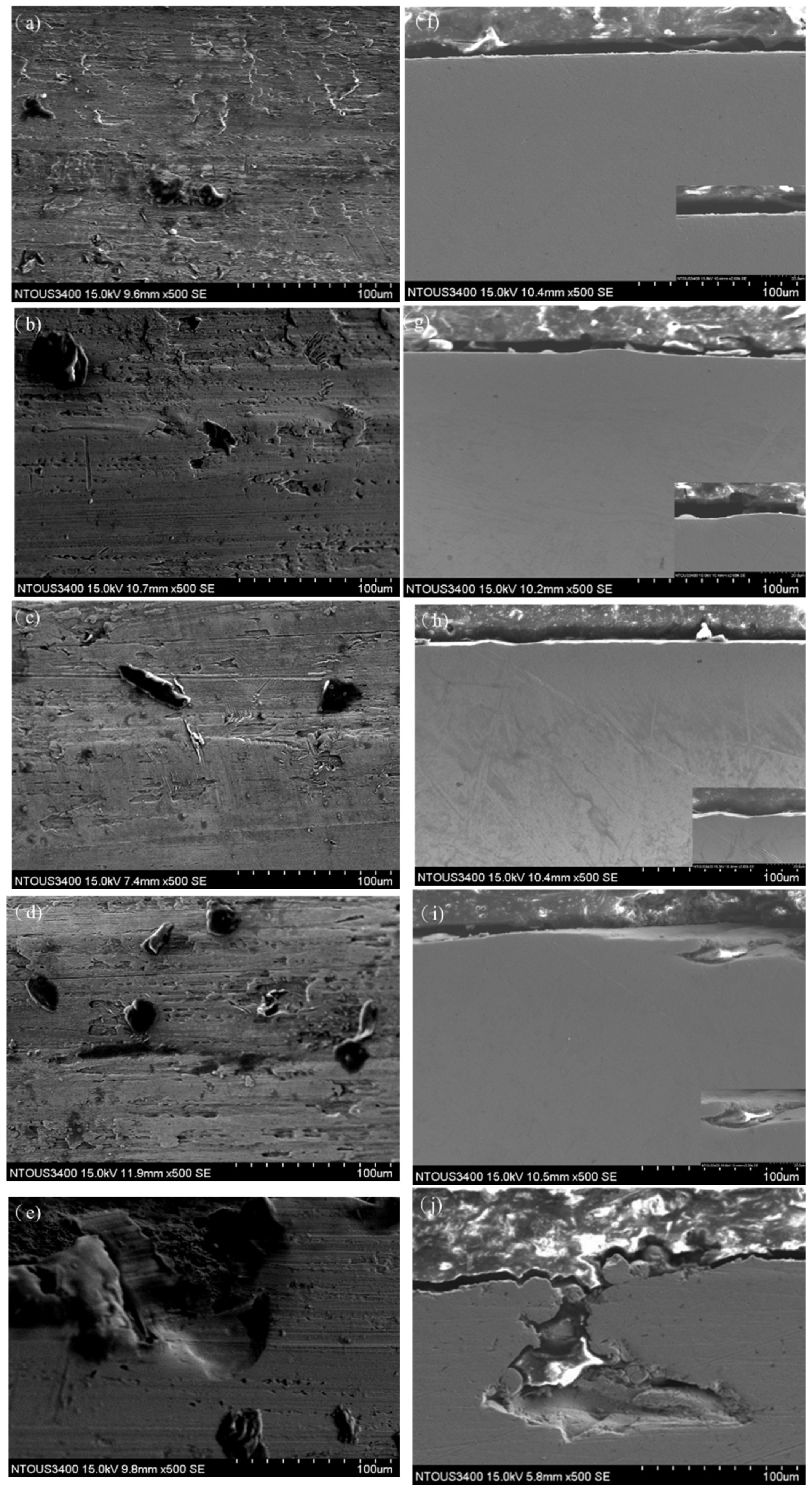
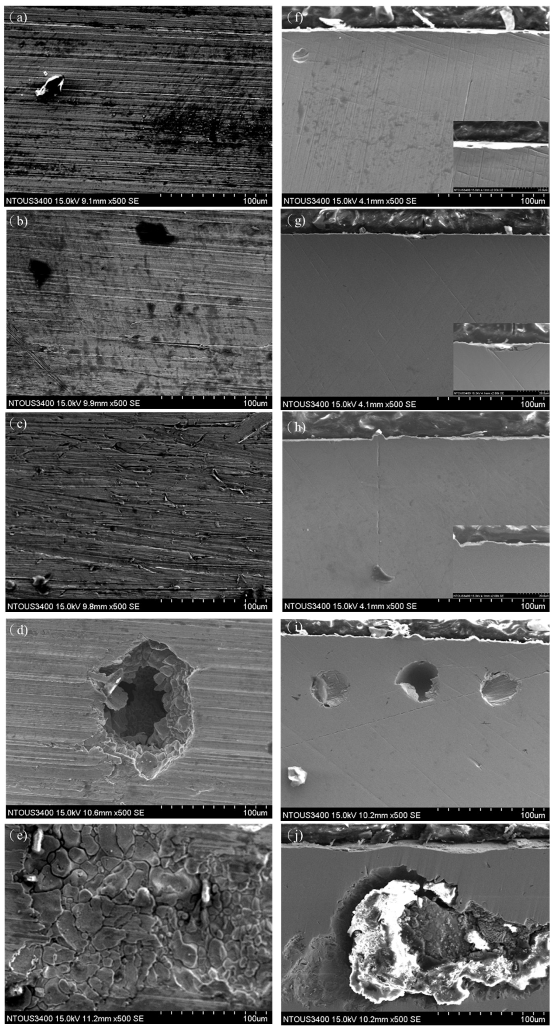
3.6. SEM Analysis Under Various Polarization Potentials

In the potentiostatic polarization corrosion and tribocorrosion tests, SEM observations of the specimen surfaces after 40 min of exposure revealed distinct differences in corrosion morphology depending on the applied potential. Under pure corrosion conditions, the bulk specimen exhibited no significant surface degradation at the activation potentials of OCP (Figure 8a) and −500 mVSCE (Figure 8b). However, at the passive region of +100 mVSCE (Figure 8d), localized pitting and flake-like exfoliation began to appear. At the transpassive potential of +500 mVSCE (Figure 8e) the passive film was disrupted, leading to extensive depassivation and the formation of large pits. Cross-sectional images showed that at +100 mVSCE (Figure 8i), subsurface pitting began to develop, and by +500 mVSCE (Figure 8j), intergranular corrosion and deep crevice-like features were evident, indicating the progression of corrosion into the substrate.
For the SLM specimens, no obvious corrosion features were observed under activation conditions at OCP (Figure 9a) and −500 mVSCE (Figure 9b). At +100 mVSCE (Figure 9d), layered exfoliation was observed, and at +500 mVSCE (Figure 9e), decomposition of the passive film accelerated corrosion, resulting in surface delamination and disintegration of matrix grains. This was primarily attributed to the inherent porosity of the SLM structure, which serves as preferential corrosion initiation sites. Cross-sectional analysis revealed inward-growing pits and grain detachment originating from pre-existing pores at +100 mVSCE (Figure 9i), while at +500 mVSCE (Figure 9j), extensive surface delamination and severe corrosion damage were observed.
Under tribocorrosion conditions, the bulk specimen exhibited lamellar exfoliation at −500 mVSCE (Figure 10b) and −300 mVSCE (Figure 10c). At +100 mVSCE (Figure 10d), localized pitting and pronounced grooves caused by adhesive wear were observed. When the potential increased to +500 mVSCE (Figure 10e), the surface showed extensive cavity formation. Cross-sectional images revealed that delamination at +100 mVSCE (Figure 10i) resulted in surface indentation, while +500 mVSCE (Figure 10j) showed evidence of crevice corrosion, prominent pits, and detachment of wear particles.
In the SLM specimens under tribocorrosion, signs of plowing, lamellar cracking, and brittle delamination were observed at −500 mVSCE (Figure 11b) and −300 mVSCE (Figure 11c). At +100 mVSCE (Figure 11d), the original porous regions of the sample developed into large pits, while at +500 mVSCE (Figure 11e), accelerated corrosion was accompanied by mechanical wear, leaving clear smearing and compaction marks. Cross-sectional observations showed that at +100 mVSCE (Figure 11i), corrosion pits and wear-induced scratches aligned with surface features; by +500 mVSCE (Figure 11j), prominent grooves and particle detachment were evident. Overall, the SLM specimens showed relatively mild corrosion damage under pure corrosion conditions but exhibited more pronounced surface degradation under tribocorrosion, highlighting their greater susceptibility to synergistic wear–corrosion interactions.

4. Discussion

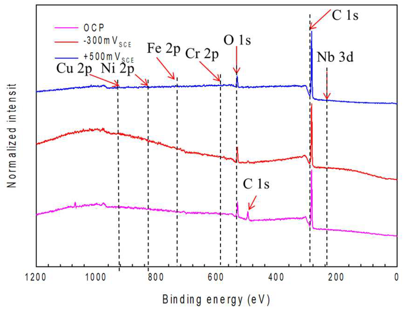
4.1. XPS Peak Analysis of Elements in the Passive Film

To further analyze the interactions of various elements with corrosion behavior in 17-4PH stainless steel, X-ray photoelectron spectroscopy (XPS) was performed on SLM-fabricated specimens exposed to seawater under different polarization potentials, including open circuit potential (OCP) +100 mVSCE and +500 mVSCE The objective was to investigate how these electrochemical conditions influence the chemical states and elemental composition within the passive film formed on the specimen surface.
As shown in the full survey spectra in Figure 12, passive films developed under different corrosion potentials exhibit generally similar spectral features; however, clear variations are observed in the peak intensities and binding energy positions of key elemental signals. These differences can be attributed to changes in the chemical state and relative abundance of elements within the film. According to the findings of Teng et al. [32], such variations arise from shifts in the chemical environment, leading to distinct binding energies for each element as their oxidation states and coordination environments change.
The primary elements contributing to the passive film can be identified from their characteristic binding energy ranges, and the analysis reveals a gradient in binding energies corresponding to a compositional variation through the film’s depth. Based on the model proposed by Shih et al. [33], the passive layer consists of a multilayered protective structure primarily composed of iron and chromium. The outermost region of the film is rich in iron species, serving as the first barrier against corrosion.
Beneath this lies an inner layer dominated by chromium compounds, which are responsible for the core corrosion resistance of the passive film. Between these two layers exists an intermediate zone containing nickel and copper, along with a moderate amount of chromium, contributing to the film’s overall structural cohesion. This stratified architecture enables the passive film to function as an integrated protective system, in which each compositional layer performs a specific role. The combination of these layers enhances both the corrosion resistance and long-term stability of the stainless steel in marine environments, particularly under varying anodic polarization conditions.
Depth profiling analysis was performed on 17-4PH stainless steel using X-ray photoelectron spectroscopy (XPS) to investigate the elemental distribution of Fe, Cr, Ni, Cu, Nb, and O along the surface-to-subsurface direction. The analysis was conducted on SLM-fabricated specimens subjected to different polarization potentials (OCP, −300 mVSCE and +500 mVSCE) in seawater. Ar+ ion sputtering was applied at 3 kV over a 2 × 2 mm area, with a calibrated etch rate of 44.72 nm/min based on SiO2. Spectral measurements were taken at 1 min intervals after each etching cycle, as shown in Figure 13a. From the depth profiles, the atomic concentration of iron under OCP conditions averaged approximately 83 at%. However, under +500 mVSCE the formation of FeO due to oxygen uptake was evident, suggesting enhanced oxidation. The FeO phase is known to be structurally loose and thermodynamically unstable, which facilitates iron ion diffusion and reduces the surface Fe concentration.
This indicates a degradation of the passive film at higher potentials. Chromium, by contrast, plays a critical role in corrosion resistance. In oxidative environments, Cr rapidly reacts with oxygen to form a dense Cr2O3 passive layer that protects the underlying metal from further oxidation and corrosive attack. The concentration of oxygen increased with increasing polarization potential from OCP to +500 mVSCE while the relative amounts of Fe, Cr, and Cu showed slight reductions, consistent with findings reported by others [34].
To identify the chemical states of the major elements, peak deconvolution was conducted using XPS Peak Version 4.0 software. Spectral fitting was performed using background subtraction methods and cross-referenced with the NIST database and recent literature to determine binding energy assignments in Table 7, For the Fe 2p spectrum at OCP Fe 2p1/2 was composed of Fe0 at 720.0 eV and Fe2+ at 723.3 eV, while Fe 2p3/2 included peaks at 706.7 eV (Fe0) and 709.6 eV (Fe2+), as shown in Figure 13b Fe2+ corresponds to FeO, the initial oxide formed during passivation. While FeO provides a preliminary barrier against environmental attack, it is less stable and can dissolve or be reduced under corrosive conditions, which compromises the long-term integrity of the passive film.
In the Cr 2p spectrum under OCP Cr 2p1/2 was represented entirely by Cr0 at 583.5 eV, whereas Cr 2p3/2 consisted mainly of Cr0 at 574.1 eV, with a minor presence of Cr3+ at 575.4 eV, indicative of Cr2O3, as shown in Figure 13c. Cr2O3 forms a compact, water-insoluble oxide layer that effectively impedes chloride ion penetration, enhancing corrosion resistance.
The Ni 2p spectrum at OCP revealed a Ni0 peak at 853.0 eV and a slight Ni2+ component at 853.4 eV corresponding to NiO, as shown in Figure 13d. The presence of NiO contributes to passivation and provides additional corrosion protection, particularly in acidic environments, by forming a nickel oxide layer within the middle region of the passive film [35].

4.2. Quantitative Analysis Results

In the analysis of tribocorrosion synergistic effects, both the bulk and SLM specimens exhibited a positively correlated increase in total mass loss (Wtotal), corrosion-induced mass loss (ΔWcorr), and mechanically induced wear loss (ΔWwear), as illustrated in Figure 14a,b. The majority of material loss occurred in the active, passive, and transpassive regions.
For the bulk specimen, the mass loss increased by approximately 10 mg from open circuit potential (OCP) to −300 mVSCE and further increased by another 20 mg from −300 mVSCE to +500 mVSCE showing an exponential growth trend. Corrosion-related loss was relatively minor in the activation region, with only about 0.4 mg increase from OCP to −300 mVSCE However, a sharp rise was observed near the transpassive potential (+100 mVSCE and beyond), likely due to intensified chloride ion attack. In terms of mechanical wear, the loss increased by about 20 mg from OCP to +500 mVSCE indicating that the wear component contributed more significantly to total degradation than pure corrosion. This increase in mass loss is primarily attributed to the rupture of the passive film during the transition from the passive to transpassive region, which led to surface delamination.
In contrast, the SLM specimen showed a greater tribocorrosion mass loss than the bulk specimen at −300 mVSCE, but the additional loss up to +500 mVSCE was only around 3 mg, reflecting a smaller variation in corrosion-related degradation. However, the overall synergistic effect was far more pronounced in the SLM sample, with total mass loss increasing by approximately 65 mg from OCP to +500 mVSCE, indicating a dominant wear-driven failure mode. This distinctive degradation behavior is likely related to the unique mechanical properties, surface morphology, and microstructural characteristics resulting from the SLM fabrication process.

4.3. Tribocorrosion Mechanism

Under tribocorrosion conditions, inherent porosity induced by the SLM fabrication process was observed within the printed specimens, as illustrated in Figure 15. These pores acted as localized stress concentrators, thereby initiating sites for brittle delamination. During sliding contact with the alumina counterbody, the applied normal load and frictional forces produced significant contact stresses, which led to notable material degradation of the alumina block itself. This highlights the pronounced influence of coupled corrosion and wear effects on material loss at the interface, especially in the presence of pores and regions of elevated stress concentration, which further accelerate material failure.
Based on experimental observations and findings by Barroux et al. [34], the role of NbC carbides in the corrosion process can be described in three distinct stages, as observed via SEM:
  • Initial corrosion stage: due to their relatively higher anodic potential, NbC carbides undergo preferential corrosion, acting as sacrificial anodes that temporarily protect the surrounding matrix.
  • Intermediate stage: progressive dissolution of NbC leads to the formation of corrosion channels, which, combined with galvanic coupling to the adjacent matrix, results in localized chromium depletion zones.
  • Final stage: after complete dissolution of NbC, the voids left behind serve as initiation sites for pitting corrosion, promoting localized attack.
In addition, based on both the current study and the mechanism proposed by Cao et al. [36], the behavior of wear debris during the tribocorrosion process follows distinct fragmentation and displacement patterns. Experimental results revealed that wear particles are ejected from the contact interface through three primary mechanisms:
  • During tribocorrosion, generated debris detaches from the contact surface and is expelled outward due to mechanical interaction.
  • Once the underlying metallic substrate is exposed due to breakdown of the passive film, further fragmentation occurs, and the fractured particles are dislodged from the surface.
  • Some debris is retained within the natural pores of the material and, through repeated contact stress, is mechanically ground into finer particles, which are eventually expelled from the pores during sliding motion.
These observations underline the complex interplay between electrochemical degradation and mechanical wear, especially in materials with microstructural features such as porosity or second-phase particles like NbC, which play dual roles in both strengthening and corrosion initiation.

5. Conclusions

  • The corrosion polarization results demonstrated that the SLM specimens exhibited superior corrosion resistance under pure corrosion conditions. This enhancement is attributed to the more uniform distribution of alloying elements and the reduction in inherent porosity after solution treatment, which collectively improve the passivation behavior of the material.
  • In contrast, the tribocorrosion polarization curves revealed that SLM specimens showed inferior corrosion resistance under simultaneous mechanical wear and electrochemical attack. The degradation was primarily caused by the expansion of pores under shear stress, which disrupted the integrity of the passive film.
  • Microstructural analysis indicated that solution treatment at 1040 °C resulted in a uniform distribution of martensite, reduced porosity, and a more homogeneous microstructure, which significantly improved corrosion resistance.
  • SEM observations confirmed that SLM specimens suffered more severe surface degradation under tribocorrosion conditions due to the preferential corrosion of pre-existing pores within the matrix, leading to localized brittle delamination.
  • Quantitative analysis further confirmed that both bulk and SLM specimens possessed excellent corrosion resistance. However, wear played a more dominant role than electrochemical corrosion in the overall material loss during tribocorrosion.
  • XPS analysis revealed that Cr2O3 formed the most compact and stable passive layer among the corrosion products. This oxide effectively prevented chloride ion penetration, thereby enhancing the long-term stability and protective capability of the passive film.
  • SLM technology offers advantages such as the ability to fabricate complex geometries and high material utilization; however, it also has drawbacks, including high equipment costs and relatively slow manufacturing speeds.

Author Contributions

Conceptualization, B.-X.H.; methodology, H.-H.S.; investigation, writing—original draft preparation, M.-Y.L.; writing—review and editing, C.-Y.L. and H.-B.L.; funding acquisition, H.-B.L. All authors have read and agreed to the published version of the manuscript.

Funding

The authors would like to acknowledge the financial support for this research by Ministry of Science and Technology, Taiwan, under Grant No. NSTC 113-2622-E-019-003.

Institutional Review Board Statement

Not applicable.

Informed Consent Statement

Not applicable.

Data Availability Statement

The original contributions presented in the study are included in the article, further inquiries can be directed to the corresponding author.

Conflicts of Interest

The authors declare that the research was conducted in the absence of any commercial or financial relationships that could be construed as a potential conflict of interest.

References

  1. Tsai, P.H.; Xiao, A.C.; Li, J.B.; Jang, J.S.C.; Chu, J.P.; Huang, J.C. Prominent Fe-based bulk amorphous steel alloy with large supercooled liquid region and superior corrosion resistance. J. Alloys Compd. 2014, 586, 94–98. [Google Scholar] [CrossRef]
  2. Lashgari, H.R.; Xue, Y.; Onggowarsito, C.; Kong, C.; Li, S. Tribological properties and corrosion behaviour of additively manufactured 17-4PH stainless steel: Effects of scanning pattern, build orientation, and single vs. double scan. Mater. Today Commun. 2020, 25, 101535. [Google Scholar] [CrossRef]
  3. Yang, K.-T.; Kim, M.-K.; Kim, D.; Suhr, J. Investigation of laser powder bed fusion manufacturing and post-processing for surface quality of as-built 17-4PH stainless steel. Surf. Coat. Technol. 2021, 422, 127492. [Google Scholar] [CrossRef]
  4. Sabooni, S.; Chabok, A.; Feng, S.C.; Blaauw, H.; Pijper, T.C.; Yang, H.J.; Pei, Y. Laser powder bed fusion of 17–4 PH stainless steel: A comparative study on the effect of heat treatment on the microstructure evolution and mechanical properties. Addit. Manuf. 2021, 46, 102176. [Google Scholar] [CrossRef]
  5. Lashgari, H.R.; Kong, C.; Adabifiroozjaei, E.; Li, S. Microstructure, post thermal treatment response, and tribological properties of 3D printed 17-4 PH stainless steel. Wear 2020, 203367, 456–457. [Google Scholar] [CrossRef]
  6. Jandyal, A.; Chaturvedi, I.; Wazir, I.; Raina, A.; Haq, M.I.U. 3D printing—A review of processes, materials and applications in industry 4.0. Sustain. Oper. Comput. 2022, 3, 33–42. [Google Scholar] [CrossRef]
  7. Ali, U.; Esmaeilizadeh, R.; Ahmed, F.; Sarker, D.; Muhammad, W.; Keshavarzkermani, A.; Mahmoodkhani, Y.; Marzbanrad, E.; Toyserkani, E. Identification and characterization of spatter particles and their effect on surface roughness, density and mechanical response of 17-4 PH stainless steel laser powder-bed fusion parts. Mater. Sci. Eng. R 2019, 756, 98–107. [Google Scholar] [CrossRef]
  8. Ponnusamy, P.; Sharma, B.; Masood, S.H.; Rashid, R.A.R.; Rashid, R.; Palanisamy, S.; Ruan, D. A study of tensile behavior of SLM processed 17-4 PH stainless steel. Mater. Today Proc. 2021, 45, 4531–4534. [Google Scholar] [CrossRef]
  9. Pasebani, S.; Ghayoor, M.; Badwe, S.; Irrinki, H.; Atre, S.V. Effect of atomizing media and post processing on mechanical properties of 17-4 PH stainless steel manufactured via selective laser melting. Addit. Manuf. 2018, 22, 127–137. [Google Scholar] [CrossRef]
  10. Kudzal, A.; McWilliams, B.; Hofmeister, C.; Kellogg, F.; Yu, J.; Taggart-Scarff, J.; Liang, J. Effect of scan pattern on the microstructure and mechanical properties of Powder Bed Fusion additive manufactured 17-4 stainless steel. Mater. Des. 2017, 133, 205–215. [Google Scholar] [CrossRef]
  11. Barroux, A.; Ducommun, N.; Nivet, E.; Laffont, L.; Blanc, C.; Blanca, C.E. Pitting corrosion of 17-4PH stainless steel manufactured by laser beam melting. Corros. Sci. 2020, 169, 108594. [Google Scholar] [CrossRef]
  12. Alnajjar, M.; Christien, F.; Bosch, C.; Wolski, K. A comparative study of microstructure and hydrogen embrittlement of selective laser melted and wrought 17–4 PH stainless steel. Mater. Sci. Eng. A 2020, 785, 139363. [Google Scholar] [CrossRef]
  13. Zhao, Z.G.; Wang, H.N.; Huo, P.G.; Bai, P.G.; Du, W.; Li, X.; Li, J.; Zhang, W. Effect of Solution Temperature on the Microstructure and Properties of 17-4PH High-Strength Steel Samples Formed by Selective Laser Melting. Metals 2022, 12, 425. [Google Scholar] [CrossRef]
  14. Liu, G.L.; Huang, C.Z.; Zou, B.; Liu, H.L.; Liu, Z.Q.; Liu, Y.; Li, C.W. The modification of corrosion resistance of 17-4PH stainless steel by cutting process. J. Manuf. Process. 2020, 49, 447–455. [Google Scholar] [CrossRef]
  15. Tavares, S.S.M.; Machado, C.L.C.; Oliveira, I.G.; Martins, T.R.B.; Masoumi, M. Damage associated with the interaction between hydrogen and microstructure in a high sulfur 17-4PH steel for studs. Eng. Fail. Anal. 2017, 82, 642–647. [Google Scholar] [CrossRef]
  16. An, S.; Eo, D.-R.; Sohn, I.; Choi, K. Homogenization on solution treatment and its effects on the precipitation-hardening of selective laser melted 17-4PH stainless steel. J. Mater. Sci. Technol. 2023, 166, 47–57. [Google Scholar] [CrossRef]
  17. Nezhadfar, P.D.; Shrestha, R.; Phan, N.; Shamsaei, N. Fatigue behavior of additively manufactured 17-4 PH stainless steel: Synergistic effects of surface roughness and heat treatment. Int. J. Fatigue 2019, 124, 188–204. [Google Scholar] [CrossRef]
  18. Lou, X.; Andresen, P.L.; Rebak, R.B. Oxide inclusions in laser additive manufactured stainless steel and their effects on impact toughness and stress corrosion cracking behavior. J. Nucl. Mater. 2018, 499, 182–190. [Google Scholar] [CrossRef]
  19. Wang, T.; Wang, M.S.; Xu, T.Z.; Wu, C.L.; Zhang, C.H.; Zhang, S.; Chen, H.T.; Chen, J. Enhancing Wear Resistance and Erosion Wear Performance of Laser Additive Manufactured 17-4PHss through Solution Aging Treatment. J. Therm. Spray Technol. 2024, 33, 2350–2366. [Google Scholar] [CrossRef]
  20. Shen, S.; Li, X.; Zhang, P.; Nan, Y.; Yang, G.; Song, X. Effect of solution-treated temperature on hydrogen embrittlement of 17-4 PH stainless steel. Mater. Sci. Eng. A 2017, 703, 413–421. [Google Scholar] [CrossRef]
  21. Wang, Z.; Grimm, M.; Lindner, T.; Schubert, F.; Winkler, K.; Berger, R.; Lampke, T. Wear and corrosion properties of low-temperature nitrocarburized 17-4PH SLM components. Surf. Coat. Technol. 2024, 494, 131399. [Google Scholar] [CrossRef]
  22. García-Hernández, C.; Naranjo, J.A.; Castro-Sastre, M.Á.; Berges, C.; Fernandez-Abia, A.I.; Martín-Pedrosa, F.; Herranz, G.; García-Cabezón, C. Enhancing wear performance: A comparative study of traditional vs. additive manufacturing techniques for 17–4pH SS. Wear 2024, 205258, 540–541. [Google Scholar] [CrossRef]
  23. Schaller, R.F.; Taylor, J.M.; Rodelas, J.; Schindelholz, E.J. Corrosion Properties of Powder Bed Fusion Additively Manufactured 17-4 PH Stainless Steel. Corrosion 2017, 73, 796–807. [Google Scholar] [CrossRef]
  24. García-Cabezón, C.; García-Hernández, C.; Castro-Sastre, M.A.; Mendez, M.Z.; Pedrosa, F.N. Heat treatments of 17-4 PH SS processed by SLM to improve its strength and biocompatibility in biomedical applications. J. Mater. Res. Technol. 2023, 26, 3524–3543. [Google Scholar] [CrossRef]
  25. Cheruvathur, S.; Lass, E.A.; Campbell, C.E. Additive manufacturing of 17-4 PH stainless steel: Post-processing heat treatment to achieve uniform reproducible microstructure. JOM 2016, 68, 930–942. [Google Scholar] [CrossRef]
  26. Tavares, S.S.M.; Pardal, J.M.; da Silva, M.R. Influence of Sulfur Content on the Corrosion Resistance of 17-4PH Stainless Steel. J. Mater. Eng. Perform. 2017, 26, 2512–2519. [Google Scholar] [CrossRef]
  27. Zhang, C.; Liu, L.; Chan, K.C.; Chen, Q.; Tang, C.Y. Wear behavior of HVOF-sprayed Fe-based amorphous coatings. Intermet 2012, 29, 80–85. [Google Scholar] [CrossRef]
  28. Garcia-Cabezon, C.; Castro-Sastre, M.A.; Fernandez-Abia, A.I.; Rodriguez-Mendez, M.L.; Martin-Pedrosa, F. Microstructure–hardness–corrosion performance of 17–4 precipitation hardening stainless steels processed by selective laser melting in comparison with commercial alloy. Met. Mater. Int. 2022, 28, 2652–2667. [Google Scholar] [CrossRef]
  29. Lin, T.J.; Sheu, H.H.; Lee, C.Y.; Lee, H.B. The study of mechanical properties and corrosion behavior of the Fe-based amorphous alloy coatings using high velocity oxygen fuel spraying. J. Alloys Compd. 2021, 867, 159132. [Google Scholar] [CrossRef]
  30. Esfandiari, M.; Dong, H. The corrosion and corrosion–wear behaviour of plasma nitrided 17-4PH. Surf. Coat. Technol. 2007, 202, 466–478. [Google Scholar] [CrossRef]
  31. Lee, C.Y.; Lin, T.; Sheu, H.H.; Lee, H.B. A study on corrosion and corrosion–wear behavior of Fe-based amorphous alloy coating prepared by high velocity oxygen fuel method. J. Mater. Res. Technol. 2021, 15, 4880–4895. [Google Scholar] [CrossRef]
  32. Rowolt, C.; Milkereit, B.; Springer, A.; Kreyenschulte, C.; Kessler, O. Dissolution and precipitation of copper-rich phases during heating and cooling of precipitation-hardening steel X5CrNiCuNb16-4 (17-4 PH). Met. Corros. 2020, 55, 13244–13257. [Google Scholar] [CrossRef]
  33. Shih, T.-S.; Huang, Y.-S.; Chen, C.-F. Constituted oxides/nitrides on nitriding 304, 430 and 17-4 PH stainless steel in salt baths over the temperature range 723 to 923K. Appl. Surf. Sci. 2011, 258, 81–88. [Google Scholar] [CrossRef]
  34. Barroux, A.; Duguet, T.; Ducommun, N.; Nivet, E.; Delgado, J.; Laffont, L.; Blanc, C. Combined XPS/TEM study of the chemical composition and structure of the passive film formed on additive manufactured 17-4PH stainless steel. Surf. Interface 2021, 22, 100874. [Google Scholar] [CrossRef]
  35. Biesinger, M.K.; Payne, B.P.; Hart, B.R.; Grosvenor, A.P.; McIntryre, N.T.; Lau, L.; Smart, R.S. Quantitative Chemical State XPS Analysis of First Row Transition Metals, Oxides and Hydroxides. Conf. Ser. 2008, 100, 012025. [Google Scholar] [CrossRef]
  36. Cao, S.; Mischler, S. Modeling tribocorrosion of passive metals—A review. Curr. Opin. Solid State Mater. Sci. 2018, 22, 127–141. [Google Scholar] [CrossRef]
Figure 1. SEM images: (a) surface and (b) cross-section of the bulk specimen; (c) metal powder used for SLM; (d) surface and (e) cross-section of the SLM specimen.
Coatings 15 00649 g001
Figure 2. Optical microscopy (OM) images of microstructures after solution treatment: (a) bulk specimen; (b) SLM specimen.
Coatings 15 00649 g002
Figure 3. Mechanical properties and analytical results of the materials: (a) contact angle; (b) Vickers hardness; (c) DSC analysis; (d) XRD analysis.
Coatings 15 00649 g003
Figure 4. Corrosion polarization curves and open circuit potentials (OCP) of 17-4PH stainless steel: (a) Polarization curve of the bulk specimen; (b) Polarization curve of the SLM specimen; (c) Open circuit potential of the bulk specimen; (d) Open circuit potential of the SLM specimen.
Coatings 15 00649 g004aCoatings 15 00649 g004b
Figure 5. Coefficient of friction under dry and wet sliding conditions: (a) bulk specimen; (b) SLM specimen.
Coatings 15 00649 g005
Figure 6. Potentiostatic polarization vs. time of 17-4PH stainless steel under 40 min constant potential testing: (a) bulk specimen in pure corrosion; (b) SLM specimen in pure corrosion; (c) bulk specimen in tribocorrosion; (d) SLM specimen in tribocorrosion.
Coatings 15 00649 g006
Figure 7. Friction coefficient curves under various polarization potentials: (a) bulk specimen; (b) SLM specimen.
Coatings 15 00649 g007
Figure 8. SEM images of the corrosion surface and cross-sectional morphologies of the bulk specimen under different polarization potentials: (a,f) OCP, (b,g) −500 mVSCE, (c,h) −300 mVSCE, (d,i) +100 mVSCE, (e,j) +500 mVSCE.
Coatings 15 00649 g008
Figure 9. SEM images of the corrosion surface and cross-sectional morphologies of the SLM specimen under different polarization potentials: (a,f) OCP, (b,g) −500 mVSCE, (c,h) −300 mVSCE, (d,i) +100 mVSCE, (e,j) +500 mVSCE.
Coatings 15 00649 g009
Figure 10. SEM images of the tribocorrosion surface and cross-sectional morphologies of the bulk specimen under different polarization potentials: (a,f) OCP, (b,g) −500 mVSCE, (c,h) −300 mVSCE, (d,i) +100 mVSCE, (e,j) +500 mVSCE.
Coatings 15 00649 g010
Figure 11. SEM images of the tribocorrosion surface and cross-sectional morphologies of the SLM specimen under different polarization potentials: (a,f) OCP, (b,g) −500 mVSCE, (c,h) −300 mVSCE, (d,i) +100 mVSCE, (e,j) +500 mVSCE.
Coatings 15 00649 g011
Figure 12. Full XPS spectra of the SLM specimen under different polarization potentials.
Coatings 15 00649 g012
Figure 13. XPS depth profiling analysis of the SLM specimen at OCP polarization potential. (a) Cross-sectional analysis (b) Iron element peak fitting (c) Chromium element peak fitting (d) Nickel element peak fitting.
Coatings 15 00649 g013aCoatings 15 00649 g013b
Figure 14. Quantitative analysis of corrosion and wear: (a) bulk specimen; (b) SLM specimen.
Coatings 15 00649 g014
Figure 15. Schematic illustration of the tribocorrosion mechanism in SLM-fabricated 17-4PH stainless steel.
Coatings 15 00649 g015
Table 1. SEM–EDS compositional analysis of 17-4PH stainless steel.
ElementsFeCrNiCuMnSiNbMoCSP
Atom%
Bulk Specimen75.5115.294.553.240.810.320.190.030.020.010.03
SLM Specimen75.6815.124.633.160.790.340.170.050.030.020.01
Metal Powder75.5715.234.753.040.750.380.160.060.030.010.02
Table 2. Corrosion current density, corrosion potential, and coefficient of friction from the polarization curves of 17-4PH stainless steel.
Bulk SpecimenEcorrIcorrFriction Coefficient
Corrosion−510 mV431.03 μA-
Corrosion wear−609 mV614.61 μA0.12
SLM specimenEcorrIcorrFriction Coefficient
Corrosion−527 mV317.82 μA-
Corrosion wear−612 mV653.19 μA0.50
Table 3. Corrosion potential, weight loss, and coefficient of friction from the open circuit potential (OCP) curves of 17-4PH stainless steel.
Bulk SpecimenPotentialWeight LossFriction Coefficient
Corrosion−524 mV5 mg-
Corrosion wear−619 mV17 mg0.11
SLM specimenPotentialWeight lossFriction Coefficient
Corrosion−553 mV2 mg-
Corrosion wear−625 mV29 mg0.51
Table 4. Test results of specimens under dry and wet sliding conditions.
17-4PH Stainless SteelBulk SpecimenSLM Specimen
Dry WearWet WearDry WearWet Wear
Friction coefficient0.560.140.690.53
Weight loss (mg)19125614
Table 5. Results of potentiostatic polarization tests (40 min constant potential) for 17-4PH stainless steel specimens under pure corrosion and tribocorrosion conditions.
mA/cm2−500 mVSCE−300 mVSCE+100 mVSCE+500 mVSCE
Bulk specimen Corrosion0.060.100.521.82
SLM specimen Corrosion0.0030.0040.090.07
Bulk specimen Corrosion wear0.080.182.824.77
SLM specimen Corrosion wear0.120.343.065.50
Table 6. Friction coefficient results under various polarization potentials.
Friction CoefficientOCP−500 mVSCE−300 mVSCE+100 mVSCE+500 mVSCE
Bulk specimen0.110.120.090.100.11
SLM specimen0.510.550.560.580.59
Table 7. XPS binding energy data of elements from NIST (USA).
ElementSpectral LineFormulaBinding Energy (eV)
NIST ReferenceExperimental on the Surface
Fe2p1/2, 2p3/2Fe720.0, 706.7706.6 [34]720.0, 706.7
Fe2p1/2, 2p3/2,
2p3/2
FeO723.3, 709.6
707.2
707.5 [34]723.3, 709.6
707.2
Fe2p3/2Fe2O3711.4711.8 [34]711.4
Cr2p1/2, 2p3/2Cr583.5, 574.1573.9 [34]583.5, 574.1
Cr2p3/2, 2p3/2Cr2O3576.2, 575.4575.8 [34]576.2, 575.4
Ni2p3/2, 2p3/2Ni853.0, 852.9852.7 [34]853.0, 852.9
Ni2p3/2NiO853.4852.8 [34]853.4
Cu2p3/2, 2p3/2Cu932.8, 932.6932.4 [34]932.8, 932.6
Cu2p3/2CuO934.6932.5 [34]934.6
NbC3d5/2, 3d5/2NbC203.7, 202.7203.6 [34]203.7, 202.7
NbC3d5/2NbCO205.8206.3 [34]205.8
Nb3d5/2, 3d5/2
3d5/2
NbO204.7, 203.8
202.8
206.9 [34]204.7, 203.8
202.8
Nb3d5/2, 3d5/2NbO2206.1, 205.8207.5 [34]206.1, 205.8
Nb3d5/2, 3d5/2Nb2O5207.1, 206.9209.6 [34]207.1, 206.9
Disclaimer/Publisher’s Note: The statements, opinions and data contained in all publications are solely those of the individual author(s) and contributor(s) and not of MDPI and/or the editor(s). MDPI and/or the editor(s) disclaim responsibility for any injury to people or property resulting from any ideas, methods, instructions or products referred to in the content.

