Article

The Effect of USRP-Composite DLC Coating on Bearing Fatigue Life

1
School of Mechanical Engineering, Qilu University of Technology (Shandong Academy of Sciences), Jinan 250353, China
2
Shandong Jindi Precision Machinery Technology Co., Ltd., Liaocheng 252035, China
*
Author to whom correspondence should be addressed.
Coatings 2025, 15(5), 616; https://doi.org/10.3390/coatings15050616
Submission received: 23 April 2025 / Revised: 19 May 2025 / Accepted: 19 May 2025 / Published: 21 May 2025

Abstract

:
Based on rolling contact fatigue life experiments, this study systematically investigates the effect of ultrasonic surface rolling processing (USRP) with a composite diamond-like carbon (DLC) coating on the rolling contact fatigue life of bearings through characterization and analysis. The results show that the USRP-composite DLC coating forms a synergistic mechanism between the coating and the substrate on the surface of specimens: the DLC coating resists surface wear with its high hardness and low friction coefficient, while USRP reduces substrate deformation and crack growth by decreasing surface roughness, increasing substrate hardness, and introducing residual compressive stress. Additionally, USRP enhances the adhesion between the coating and the substrate. The average wear volume of the USRP-composite DLC-coated specimens is 3.73 × 1011 μm3, which is 30.95% lower than that of USRP-treated specimens and 85.38% lower than that of untreated specimens. The average fatigue life of the USRP-composite DLC-coated specimens is 6.55 × 10⁶ cycles, which is 94.94% higher than that of USRP-treated specimens and 208.24% higher than that of untreated specimens.

Graphical Abstract

1. Introduction

Bearings, often referred to as the “joints of industry”, are critical components that support rotating mechanical systems, transmit loads, and mitigate friction and wear. Widely used in automotive, aerospace, medical equipment, and other fields, their performance directly influences the machining precision, operational stability, and reliability of mechanical equipment [1,2,3,4]. Statistics show that the global economic losses caused by bearing failures exceed one trillion U.S. dollars annually. The main causes of failure are concentrated on surface wear issues that occur during operation, including typical modes such as abrasive wear, adhesive wear, and fatigue wear—all of which are closely related to surface properties [5,6,7,8]. Surface strengthening technology employs physical, chemical, or mechanical means to selectively enhance critical surface properties such as hardness, wear resistance, corrosion resistance, and fatigue resistance without altering the bulk material properties. This extends component service life and expands application scope [9,10,11], making it a core technological pathway for addressing surface failure issues in bearings.
Ultrasonic surface rolling processing (USRP) is a surface deformation strengthening technology that integrates high-frequency ultrasonic vibrations with static pressure. By applying mechanical vibration and pressure, the microstructural reconstruction and property optimization of material surfaces are achieved, inducing controlled plastic deformation in the surface layer [12]. In 1951, the development of the first industrial ultrasonic processing machine by U.S. scholars marked the onset of ultrasonic technology’s industrial application. Studies have demonstrated that USRP can significantly enhance material surface characteristics [13,14]. For example, Wu et al. [15] prepared linear and cross textures with varying step distances on GCr15 steel surfaces via USRP, revealing that ultrasonic rolling texture treatment improves friction and wear performance through the synergistic effects of matrix strengthening, reduced real contact area, and wear particle capture. Zhang et al. [16] investigated the influence of USRP with different rolling loads on the microstructure and rolling contact fatigue behavior of 17Cr2Ni2MoVNb steel, finding that specimens treated with a 1000 N rolling load exhibited a maximum average fatigue life of 3.71 × 10⁶ cycles. Most studies consistently agree that USRP exhibits significant advantages in material surface modification, mechanical property optimization, and tribological regulation. However, when faced with complex operational challenges, the technology still suffers from limitations in deep-layer property regulation and insufficient durability of surface-modified layers under complex environments.
DLC (Diamond-Like Carbon) coating is a surface deposition technology that constructs a dense protective layer by reorganizing carbon-atomic hybridization states. This process creates a high-hardness, low-friction-coefficient coating composed of sp3 diamond phase and sp2 graphite phase on the material surface, thereby optimizing interfacial characteristics [17]. The successful preparation of the first-generation DLC coating in 1971 signaled the field’s entry into the experimental exploration stage. Mou et al. [18] studied the impact wear and damage mechanisms of DLC films on TC4 and 9Cr18 alloys, finding that both thin and thick DLC films exhibited excellent impact wear resistance. Among these, the DLC film provided the smallest volume loss (1.5 × 104 μm3). Milewski K et al. [19] investigated DLC coatings on roller bearings for belt conveyors, discovering that the wear marks on the outer rings of DLC-coated bearings were significantly smaller than those of uncoated ones. In harsh working environments, the service life of DLC-coated bearings was three times longer than that of uncoated bearings. Ye et al. [20] prepared Cr/Cr-W/W-DLC/DLC multi-layer coatings on 5A06 aluminum alloy. The study revealed that these multi-layer coatings showed excellent tribological properties at room temperature and 0 °C, primarily attributed to the formation of transfer layers and graphitization. However, at −50 °C and −100 °C, the friction coefficient and wear rate of the coatings increased significantly, reaching 0.30 and 0.77, as well as 4.24 × 10⁻⁶ mm3/Nm and 9.06 × 10⁻⁶ mm3/Nm, respectively. Low temperatures inhibited the graphitization process and induced water molecule oxidation and capillary effects, thereby deteriorating the tribological properties of the coatings. Although DLC coatings possess a series of excellent physical, mechanical, biomedical, and tribological properties—such as high hardness, low friction coefficient, chemical stability, low thermal expansion coefficient, and infrared transparency—they also have limitations, including insufficient interfacial adhesion, complex preparation processes, and high costs.
In industrial scenarios with increasingly demanding surface performance requirements under complex operating conditions, researchers are adopting composite surface strengthening technologies. These technologies integrate multiple surface enhancement methods to construct multi-level, multifunctional composite strengthening systems. Leveraging the synergistic effects of different techniques, they achieve performance improvements unattainable by individual methods, meeting the industry′s heightened demands for material reliability and functionality. Duan et al. [21] studied the effects of combined shot peening and USRP on the rolling contact fatigue performance and crack propagation of AISI 52100 steel, showing that composite treatment formed a nano-gradient structure on the surface, significantly increasing surface hardness and residual stress while minimizing surface roughness, thus remarkably enhancing fatigue life. The SP4 + USR2 specimens achieved 19.8361 × 10⁶ cycles, 14.4 times that of the untreated specimens. Tillmann et al. [22] combined plasma nitriding with DLC technology and found that plasma nitriding followed by repolishing significantly improved the tribological properties of the DLC coatings. Among them, the T-N-P process obtained the lowest friction coefficient of 0.12 ± 0.05. Although composite surface strengthening technologies offer significant advantages, such as synergistic modification through multiple processes and complementary performance benefits, they also have limitations, including challenges in multi-technology coordination, uneven interfacial bonding states, and high requirements for equipment compatibility.
At present, both USRP and DLC coating technologies have demonstrated significant advantages in enhancing material surface properties, but they each have limitations when applied individually. Meanwhile, systematic research on the specific effects of USRP-composite DLC coating on bearing fatigue life and its synergistic optimization mechanism remains limited. Based on this, the present study uses GCr15 bearing steel as the research object, applying USRP and depositing DLC coatings on the substrate surface. Through rolling contact fatigue life experiments and related characterizations, the study deeply explores the influence and mechanism of USRP-composite DLC coating on the rolling contact fatigue life of bearings. This research not only provides theoretical support for solving the problem of bearing surface failure under complex working conditions, but also is expected to promote cross-technology integration and innovation in surface strengthening technologies. It offers key technical pathways and engineering application references for improving bearing performance and facilitating the intelligent transformation of the industry.

2. Experimental Scheme

2.1. Test Materials

The substrate material used in this study is GCr15 bearing steel, and its main physical property parameters are listed in Table 1. The bearing designation employed in the rolling contact fatigue life experiment is the NTN 51305 single-direction thrust ball bearing (NTN Corporation, Osaka, Japan), as illustrated in Figure 1. Specifically, Figure 1a shows the bearing ring, Figure 1b the rolling elements, and Figure 1c the cage. The parameters of this bearing are detailed in Table 2. In the material wear resistance experiment, a material surface with a surface roughness (Ra) of 0.5 μm serves as the standard wear test surface. Frictional testing between materials with this roughness allows for precise evaluation of the material’s intrinsic wear resistance. Based on this, the test specimens used in this experiment are GCr15 bearing steel components with a surface roughness of Ra = 0.5 μm, dimensional specifications of 60 mm × 5 mm (diameter × height), and an M6 internal bore, as illustrated in Figure 1d.

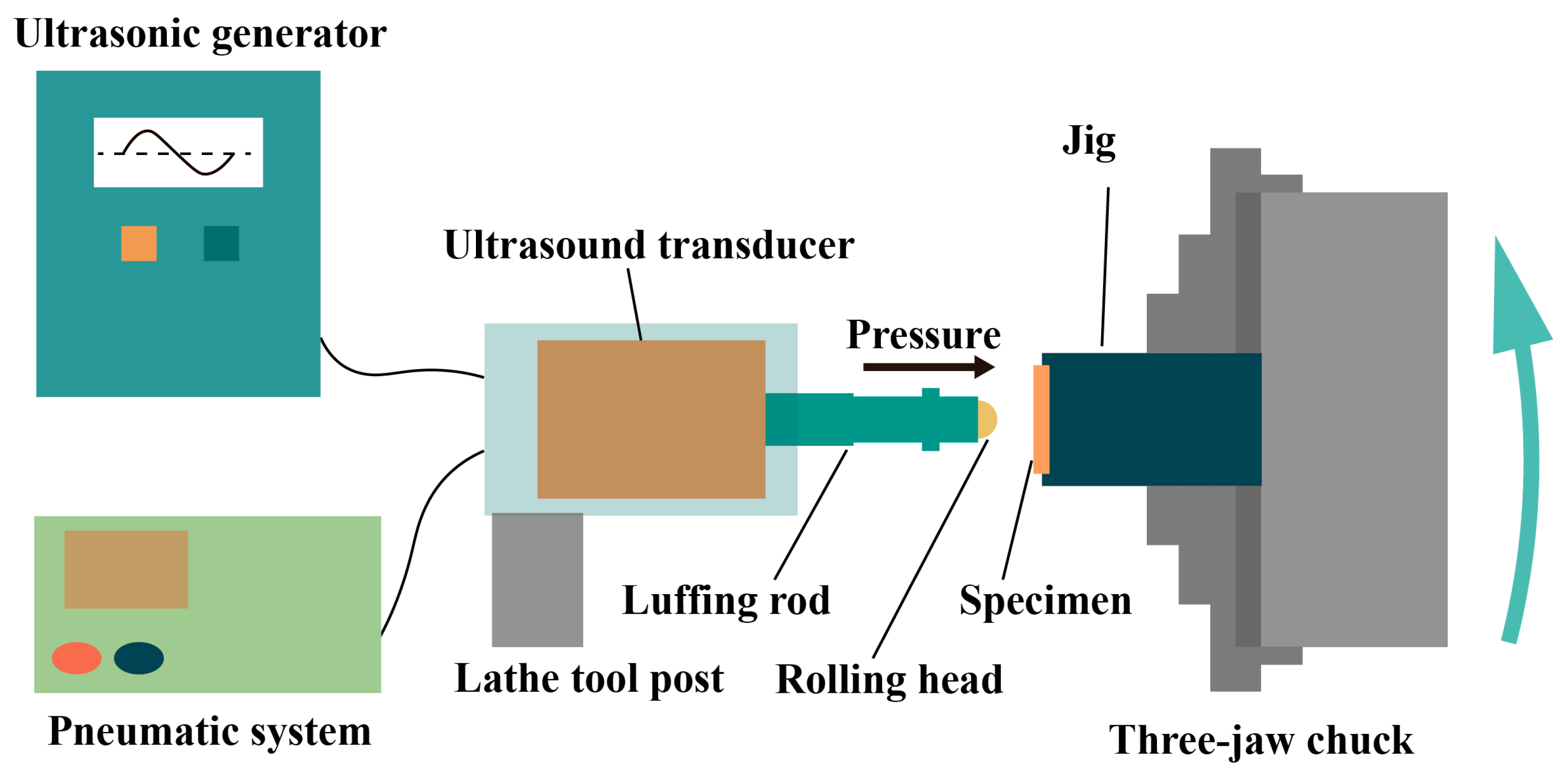
2.2. Ultrasonic Surface Rolling Processing

The schematic diagram of the ultrasonic surface rolling processing system is shown in Figure 2. This device is fixed to the lathe tool post system, and its working principle is as follows: The ultrasonic generator in the ultrasonic control cabinet converts industrial-frequency alternating current into high-frequency electrical signals, which are then transformed into mechanical vibrations of the same frequency by a transducer. These vibrations are amplified by the luffing rod and delivered to the specimen surface through a rolling head. The static pressure applied by the rolling head is provided by a pneumatic system and precisely controlled via a pressure regulating valve. During processing, the rotation of the lathe spindle and the feed motion of the tool post work in coordination to drive the rolling head to perform ultrasonic rolling on the surface of the specimen held in the fixture, enabling uniform ultrasonic surface treatment.
USRP is carried out in an environment with a temperature of 20 ± 1 °C and a relative air humidity of 40%–50%. Before processing, substrate specimens are ultrasonically cleaned in absolute ethanol and acetone to remove surface contaminants. The ultrasonic surface rolling equipment and fixture are fixed on a CKD6140i CNC lathe (Dalian Machine Tool Group, Dalian, China). The selected process parameters for ultrasonic surface rolling are as follows: a rolling pressure of 590 N, ultrasonic power of 500 W, and three rolling passes. Uniform rolling of the test specimens is achieved by the lathe tool post feeding along the positive Y-axis direction at a decelerated speed, ensuring consistent surface treatment across the specimen surface.

2.3. DLC Coating Deposition

The DLC coating was deposited using a Naxau-P850C system (Naxau, Jiaxing, China) via a combination of magnetron sputtering and plasma-enhanced chemical vapor deposition (PECVD). First, GCr15 specimens were ultrasonically cleaned in petroleum ether, absolute ethanol, and deionized water for 10 min each, followed by drying with nitrogen gas. Before deposition, the chamber was evacuated to 4 × 10⁻³ Pa, heated to 180 °C, and purged with argon (Ar, 300 sccm) for 3 min to clean the specimen surface via Ar⁺ ion bombardment. Subsequently, Cr and WC transition layers were deposited using gradient concentrations, with the power of the corresponding targets set to 8000 W. The deposition durations were 15 min for Cr and 40 min for WC. After turning off the Ar gas, acetylene (C2H2, 800 sccm) was introduced for 15 min while adjusting the bias voltage to −740 V, resulting in a 3-μm-thick DLC coating.

2.4. Surface Property Characterization

To investigate the effects of USRP and DLC coating on the surfaces of the specimens, the following characterizations were conducted. The surface roughness (Ra) of specimens was measured using a Mitutoyo SJ-210 surface roughness tester (Mitutoyo Corporation, Kawasaki, Japan). The surface topography of the specimens was observed multi-dimensionally using a VHX-5000 3D Digital Microscope (KEYENCE Corporation, Osaka, Japan) with ultra-depth-of-field, a Contour Elite K 3D Optical Microscope (Bruker Corporation, Karlsruhe, Germany), and a Helios G4 CX Focused Ion Beam (FIB) System (FEI Company, Hillsboro, OR, USA). The surface microhardness of specimens was measured using an HXD-1000TMC microhardness tester (Shanghai Optical Instrument Factory, Shanghai, China). The residual stress of specimens was measured using an X-RAYBOT residual stress online detection system (MRX Technologies, Paris, France). To explore the effect of USRP on the adhesion of DLC coating to the specimen’s surface, an RST3 high-load scratch tester (Anton Paar, Zurich, Switzerland) was used with a loading rate of 60 N/min, loading from 0 to 90 N over a scratch length of 5 mm. The final results of each test were taken as the average value of measurements conducted at three different positions for each sample.

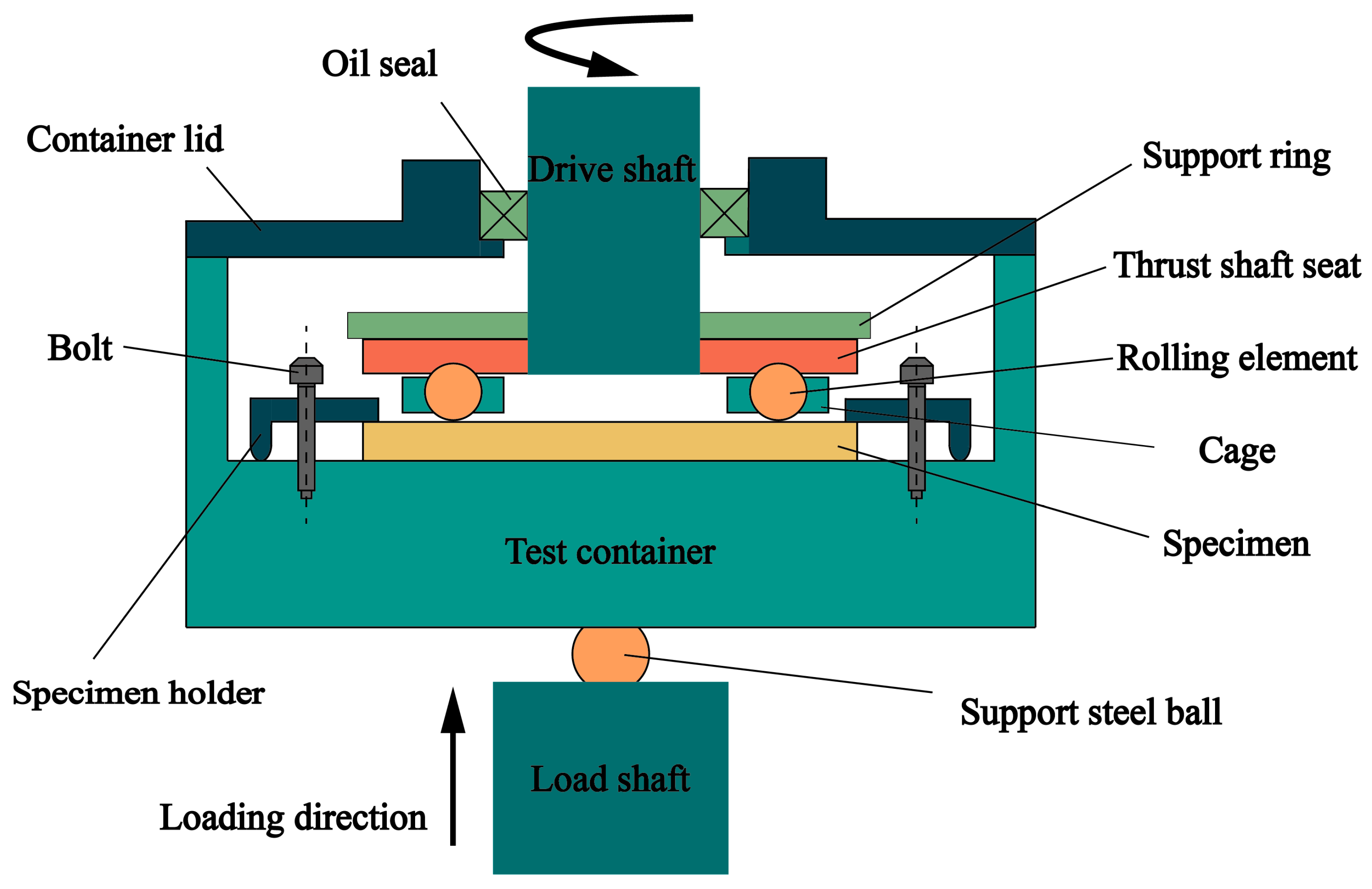
2.5. Fatigue Life Experiment

To investigate the effects of USRP and DLC coating on the rolling contact fatigue life of bearings, a TRF-1000/2 rolling fatigue tester (Tokyo Hengji Corporation, Tokyo, Japan) was used following the JB/T 10510-2005 standard [23]. Experiments were conducted under controlled conditions of 20 ± 1 °C temperature and 40%–50% relative humidity, using 46-grade anti-wear hydraulic oil. A schematic diagram of the rolling fatigue test is shown in Figure 3. The test bearing was driven by a drive shaft to rotate the support ring at 1500 r/min, while a 2500 N load was applied to the test specimens through a loading shaft, support steel balls, and a test container.
During the contact fatigue test, fatigue damage gradually developed on the surface of the specimen as the load was applied and the bearing rotation cycles increased. When rolling elements passed over damaged areas, vibration signals were generated, monitored in real time by an amplitude sensor, and converted into electrical signals. If the vibration amplitude exceeded the preset threshold (G = 3, where “G” is the unit of vibration acceleration, representing a multiple of standard gravitational acceleration), the system identified fatigue damage, automatically stopped the tester, and recorded the current number of rotation cycles and the test time. By comparing the fatigue life and surface topographical features of specimens, including wear scar depth and crack propagation, the effects of USRP-composite DLC technology on the fatigue life of GCr15 bearings were systematically explored. Untreated specimens, USRP-treated specimens, and USRP-composite DLC-coated specimens are denoted as N, U, and UD, respectively. Each group of specimens was tested five times to ensure that the data volume met the requirements of statistical analysis, thereby obtaining results with statistical significance and reliability.

3. Results

3.1. Surface Properties

Figure 4 presents the surface morphology of N, U, and UD. Figure 4a shows the surface topography of N after grinding. Figure 4b displays the surface morphology of U, where a distinct boundary between the USRP-treated rolled area and the untreated area is observable, with the processed region exhibiting enhanced surface reflectivity compared to the untreated area. Figure 4c shows UD′s surface morphology after DLC coating deposition, characterized by a dark gray coloration, while maintaining a clear interface demarcation between the rolled and untreated areas.

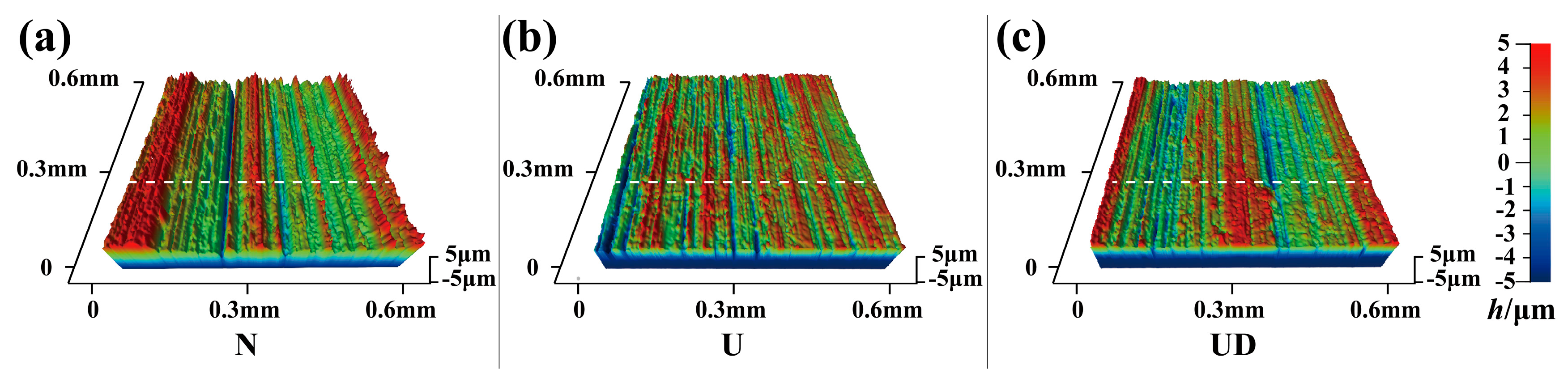
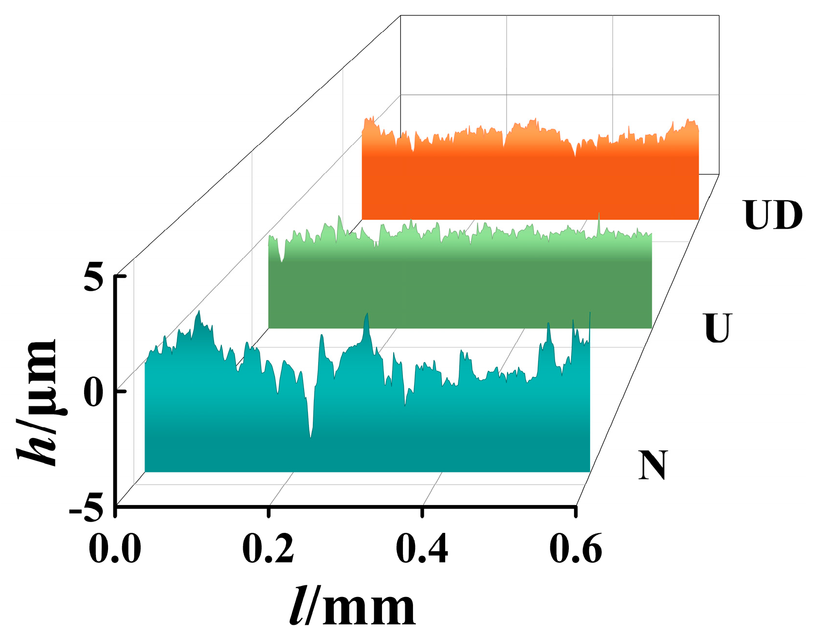
3.1.1. Surface Roughness
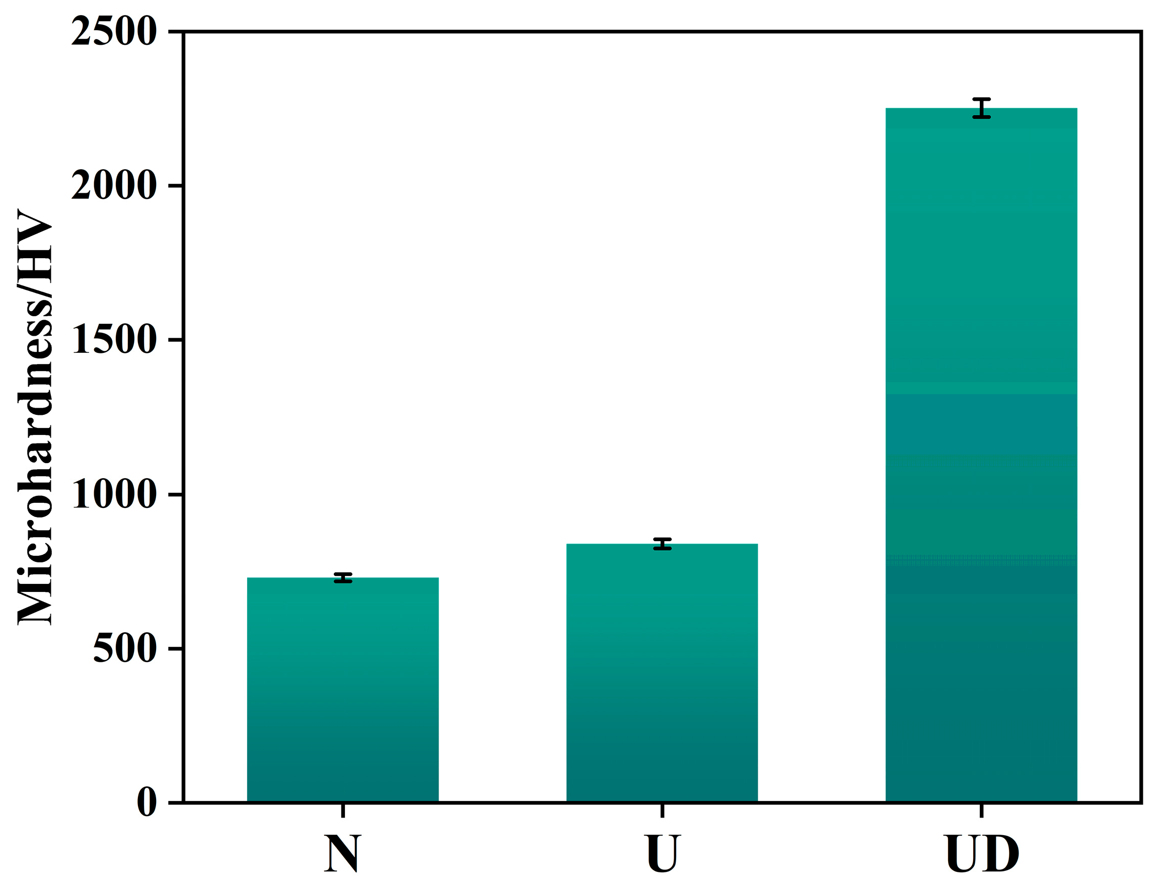
As shown in Figure 5, the micro-cutting and extrusion effects of abrasive grains during grinding result in a higher surface roughness of 0.5 μm for the N. After USRP, the surface roughness of the U decreases to 0.22 μm, representing a 56% reduction compared to N. The rolled area of the UD exhibits a surface roughness of 0.38 μm, a 24% decrease relative to N. To systematically and visually investigate the surface roughness changes among the N, U, and UD substrates, their 3D surface topographies and cross-sectional profiles are presented in Figure 6 and Figure 7, respectively.
Figure 6 presents the 3D topographies of N, U, and UD. In Figure 6a, the surface of the N shows numerous high peaks and deep valleys due to grinding. In contrast, Figure 6b reveals that the U’s surface, under the mechanism of USRP, has its peaks flattened and valleys filled, significantly improving the overall surface flatness compared to N. As shown in Figure 6c, after DLC coating deposition, the surface roughness of the UD slightly increases due to the growth of the DLC coating layer [24].
Observation of the cross-sectional profiles of N, U, and UD in Figure 7 reveals that the surface undulations of N are more pronounced with numerous peaks and valleys, while the U surface exhibits characteristics of reduced peak heights and filled valleys, leading to significantly decreased relative undulations and overall flattening. From the cross-sectional morphology of UD, it can be seen that after DLC coating deposition, the number of individual sharp protrusions decreases and adjacent valleys are partially filled, but the overall topographical unevenness increases.
By comparing the cross-sectional SEM images (a) and (b) in Figure 8, it can be observed that at the interface between the DLC coating and the substrate, USRP smoothed the peaks and valleys on the substrate surface, reducing stress concentration at the coating–substrate interface. After depositing the DLC coating, the 3 μm-thick DLC coating became flatter due to the influence of the substrate, which can reduce stress concentration on the coating surface at the start of friction. Additionally, USRP formed micro-grooves on the substrate surface, increasing the contact area between the coating and the substrate, thereby enhancing the coating–substrate adhesion.

3.1.2. Hardness

Figure 9 shows the surface hardness of N, U, and UD. Microhardness testing revealed that the surface microhardness of the N was 730 HV. During USRP, high-frequency vibrations drive the rolling tool to apply cyclic loads to the specimen surface, inducing severe plastic deformation and increasing the surface microhardness to 840 HV—an increase of approximately 15.07% compared to the N. After DLC coating deposition, the microhardness of the UD substrate reached 2252 HV.

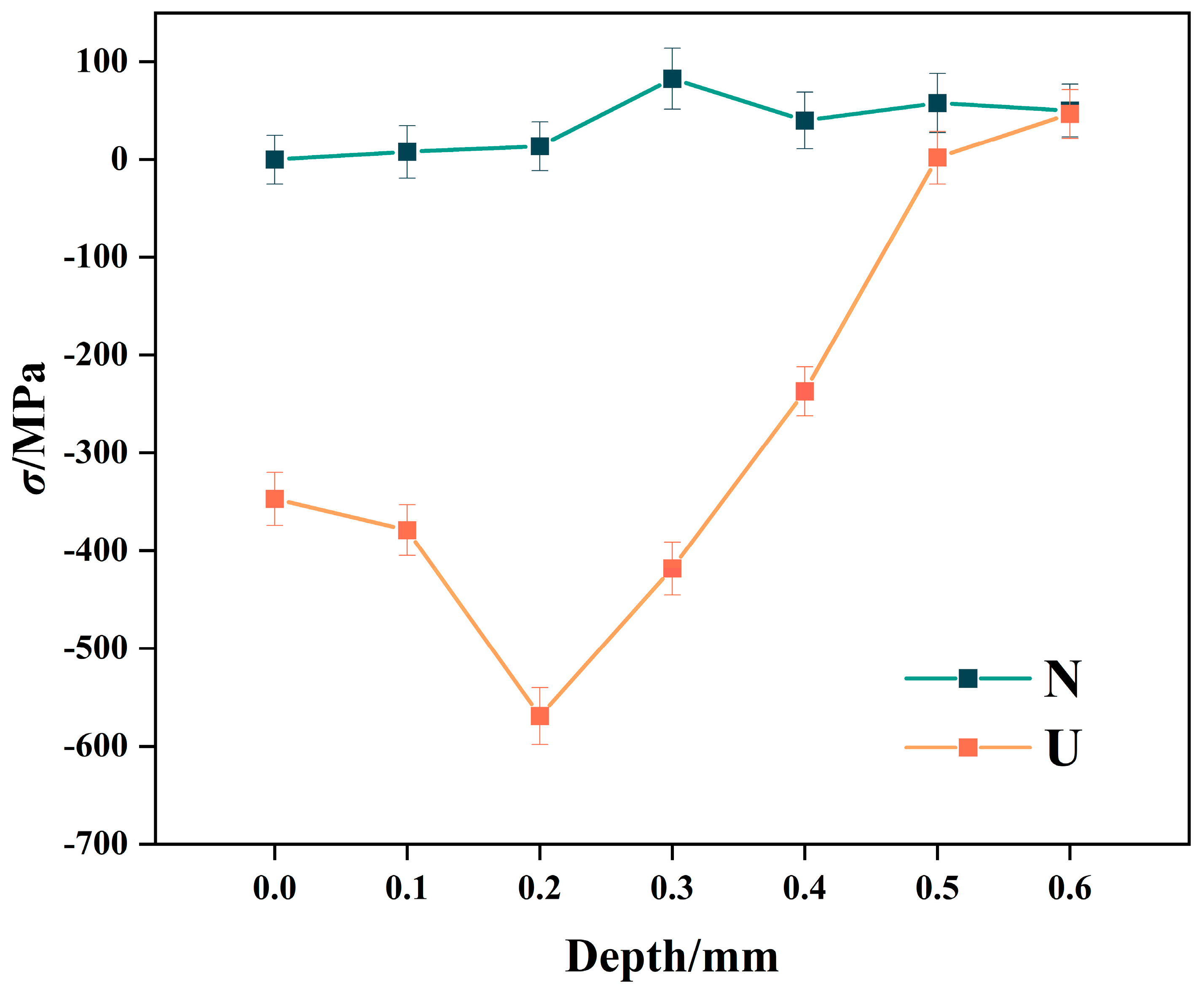
3.1.3. Residual Stress

During USRP, the generation of residual compressive stress can enhance the micro-crack closure effect, effectively inhibiting the initiation and propagation of fatigue cracks. Residual stress testing on the surfaces of the specimens showed that the N had a surface residual stress of 0, the U exhibited a surface residual compressive stress of −347 MPa, and the UD had a surface residual compressive stress of −361 MPa. During DLC coating deposition, mismatches in the thermal expansion coefficients between the coating and the GCr15 bearing steel substrate induce stress deformation at the bonding interface, leading to the generation of residual compressive stress [25]. Due to project and equipment limitations, the depth-direction residual stress of UD was not measured. Future work will investigate the influence of DLC coating deposition on the depth-direction residual stress of specimens. As shown in Figure 10, the depth-direction residual stress profiles of N and U reveal that USRP introduces a residual compressive stress layer with a depth of 0.6 mm in the U, with a maximum residual compressive stress of −569 MPa. The specific mechanism is as follows: continuous impact and applied pressure from the rolling head cause plastic deformation on the substrate surface, while the subsurface layer undergoes elastic deformation. The plastic deformation of the surface layer restricts the recovery of elastic deformation in the subsurface layer, leading to the formation of a residual compressive stress distribution along the depth direction of the substrate.

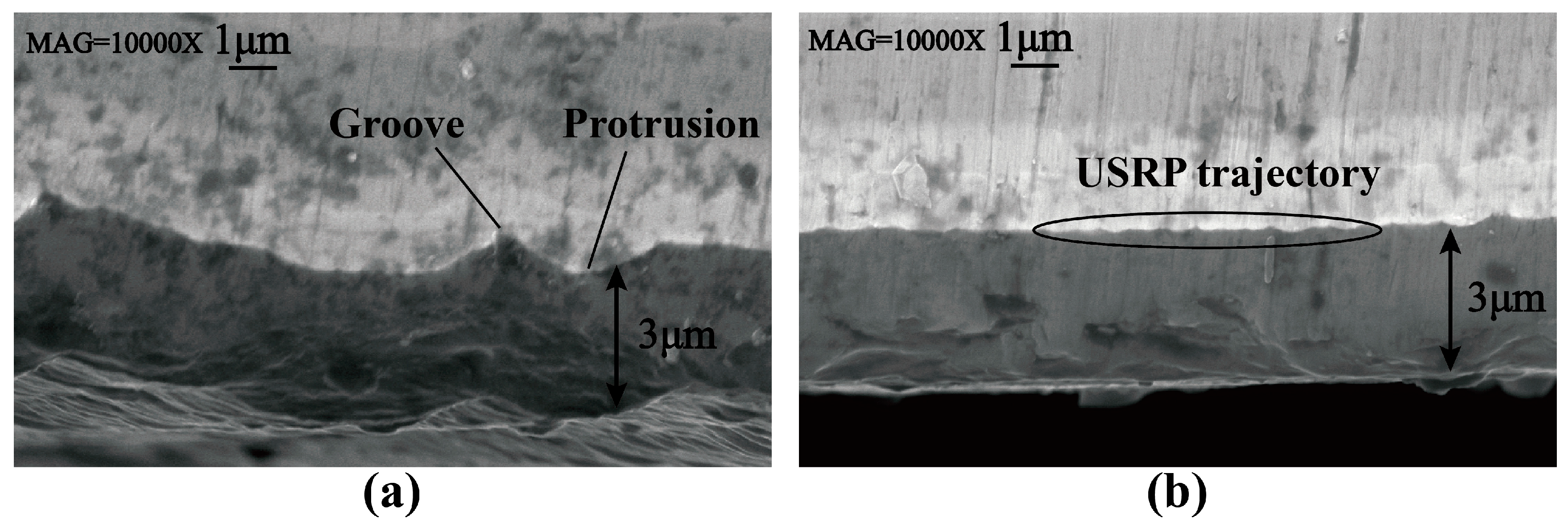
3.2. Coating Adhesion

Based on the characteristics of the scratch test, the testing process was divided into three stages, as shown in Figure 11a. To effectively quantify the coating adhesion, the adhesion was defined as the average of the loads at the end of the first stage and the end of the second stage.
(1)
Stage 1 (No Delamination Zone): At lower applied loads, the scratch gradually forms and widens, but the coating does not delaminate, and the substrate remains unexposed.
(2)
Stage 2 (Partial Delamination Zone): As the loading force increases, the scratch track expands to a wider area, and the coating undergoes localized damage. Semicircular delamination and edge cracks are observed within the scratch track, with minimal substrate exposure beginning to occur.
(3)
Stage 3 (Complete Delamination Zone): When the loading force exceeds the coating’s adhesion threshold, large-scale delamination occurs within the scratch track, exposing the substrate extensively. Subsequent scratches exhibit bright tracks corresponding to the bare substrate surface.
From the scratch test, the average adhesion force of the USRP-untreated composite DLC coating was 43.17 ± 1.83 N, and that of the USRP-treated composite DLC coating was 54.5 ± 1.51 N. Figure 11 shows a set of test results closest to the average values. For the USRP-untreated composite DLC coating, the load when transitioning from Stage 1 to Stage 2 was 26.2 N, and the load when transitioning from Stage 2 to Stage 3 was 60.3 N, yielding an adhesion value of 43.25 N (calculated as the average of the two loads). For the USRP-treated composite DLC coating, the transition loads from Stage 1 to Stage 2 and Stage 2 to Stage 3 were 36 N and 73.2 N, respectively, resulting in an adhesion value of 54.6 N.
The magnitude of coating–substrate adhesion strength is influenced by multiple internal and external parameters such as the coating′s surface roughness, contact area, and residual stress [26]. USRP improves the adhesion between the DLC coating and substrate by reducing substrate surface roughness, increasing the coating-substrate contact area, and enhancing surface residual compressive stress.

3.3. Fatigue Life

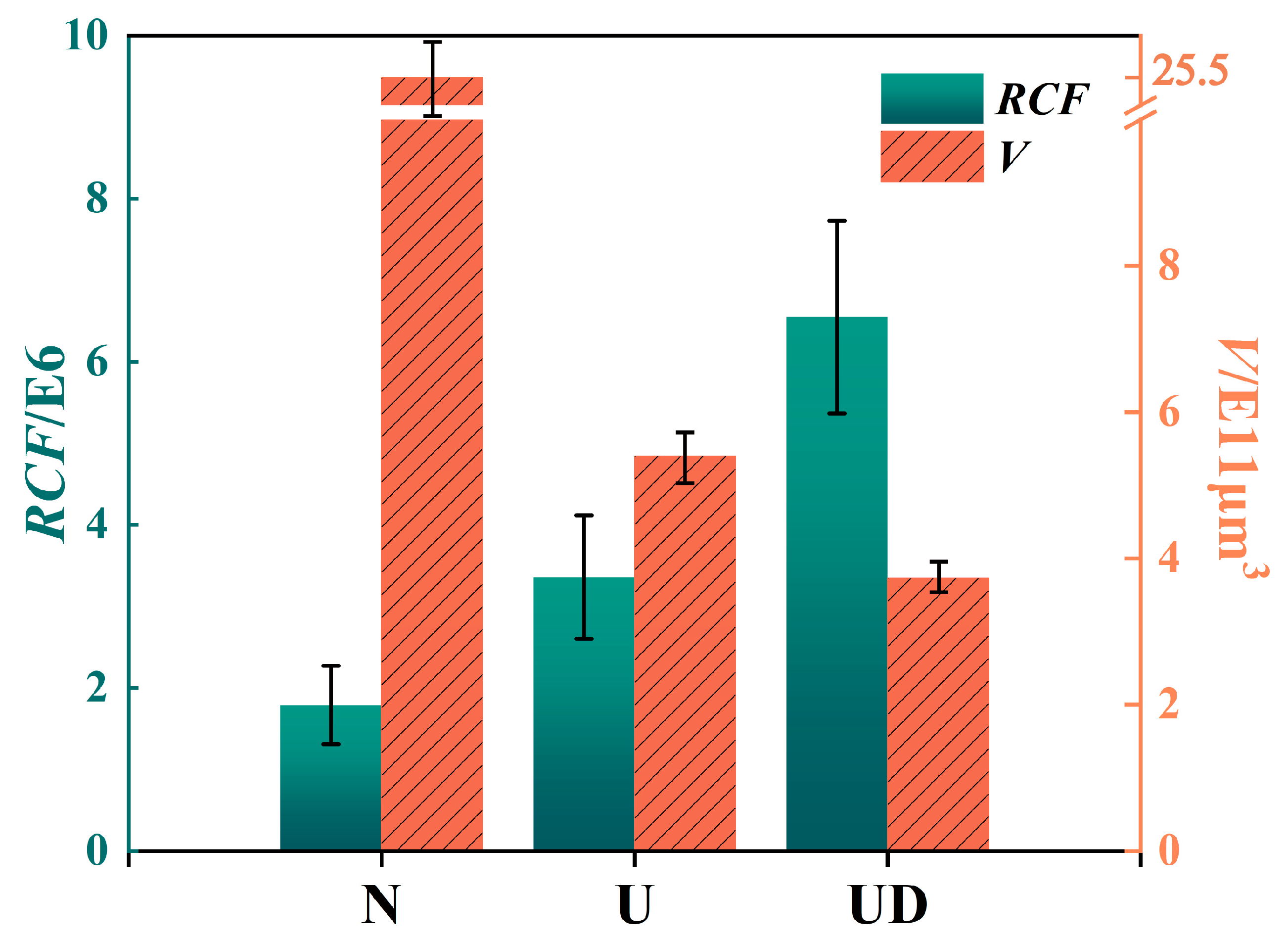
3.3.1. Rolling Contact Fatigue Life and Wear Volume

Figure 12 presents the results of the rolling contact fatigue life and wear volume for N, U, and UD. As shown, the average number of rolling fatigue cycles for the N was 1.79 × 10⁶ cycles. The U treated with USRP exhibited a significant improvement in fatigue life, with an average of 3.36 × 10⁶ cycles. The UD with USRP-composite DLC coating performed best, achieving an average of 6.55 × 10⁶ cycles. Compared to N, the average fatigue life of U increased by 65.88%, while that of UD increased by 208.24%—more than tripling the fatigue life of the untreated N. The average wear volume of N is 25.5 × 1011 μm3, that of U is 5.4 × 1011 μm3, and that of UD is 3.73 × 1011 μm3, which is 30.95% lower than that of U and 85.38% lower than that of N.

3.3.2. Analysis of Variance (ANOVA) for Rolling Contact Fatigue Life

Table 3 presents the results of rolling contact fatigue life. To verify whether the mean differences among the experimental results of the three groups (N, U, and UD) have statistical significance, analysis of variance (ANOVA) was performed on the rolling contact fatigue life data. Table 4 shows the ANOVA results for rolling contact fatigue life, indicating that p = 0.000015 < 0.05 and F = 32.097 > 3.89. The results reveal that there were significant between-group differences in the fatigue life of the three groups of bearings.

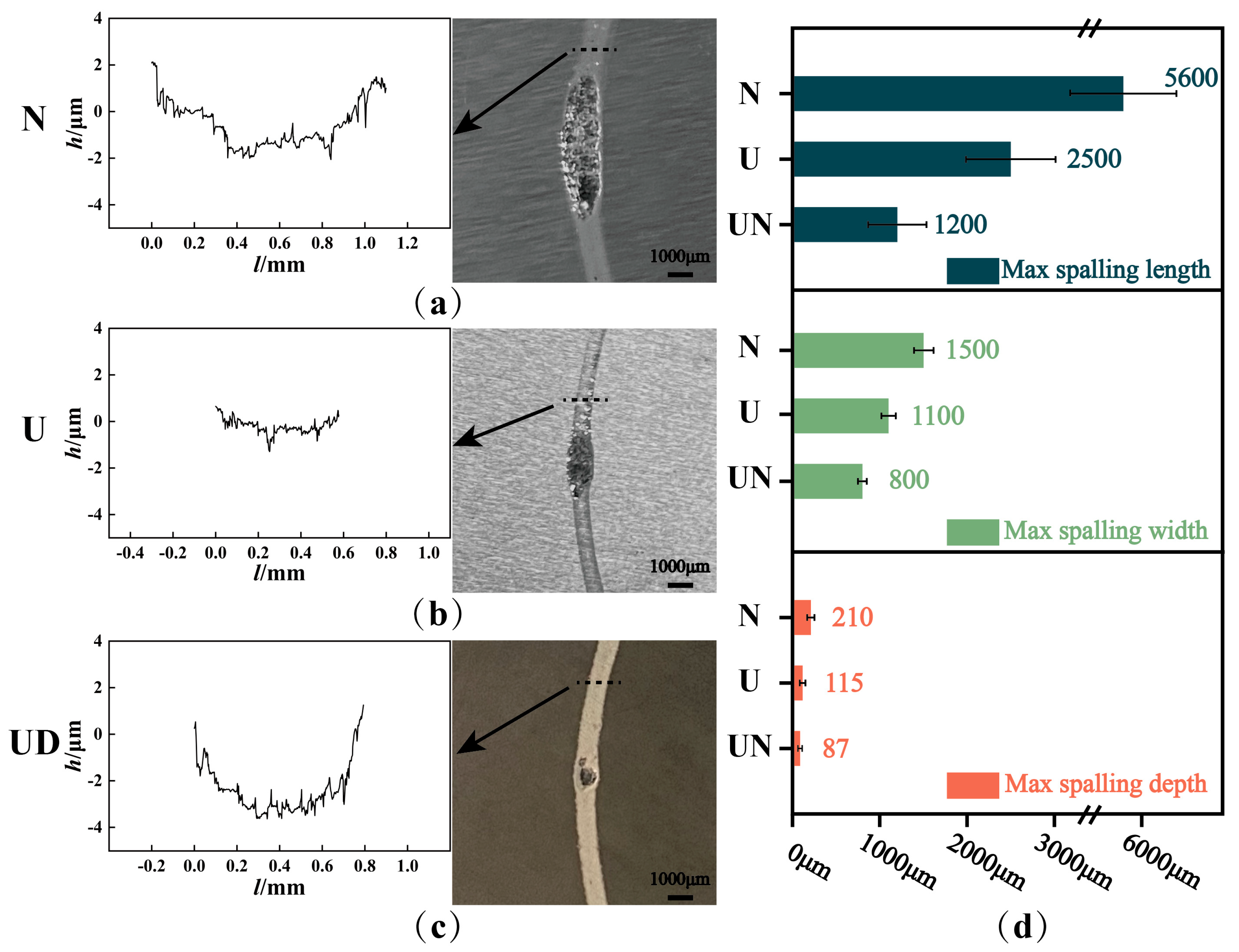
3.4. Analysis of Rolling Contact Fatigue Failure Morphology

Based on the rolling contact fatigue life results, significant differences exist among the N, U, and UD groups. To investigate the causes of these differences, the surface morphology of fatigued specimens was analyzed.
Figure 13 shows the comparison of wear scars and maximum spalling sizes after the rolling contact fatigue test. In Figure 13a, the N exhibits a wear scar width of 1.1 mm and a depth of 4 μm. Figure 13b reveals that the U has a narrower wear scar (0.6 mm width, 2 μm depth) due to USRP treatment. For the UD in Figure 13c, the measured wear scar width and depth were 0.8 mm and 4 μm, respectively; however, considering the 3-μm-thick DLC coating deposited during processing, the actual wear scar width and depth were corrected for coating thickness and were determined to be 0.5 mm and 1 μm, respectively. Figure 13d compares the maximum spalling sizes: the N shows the largest spalling pit with a length of 5600 μm, width of 1500 μm, and depth of 210 μm, while the UD has the smallest values (1200 μm length, 800 μm width, and 87 μm depth), demonstrating significantly reduced surface damage.

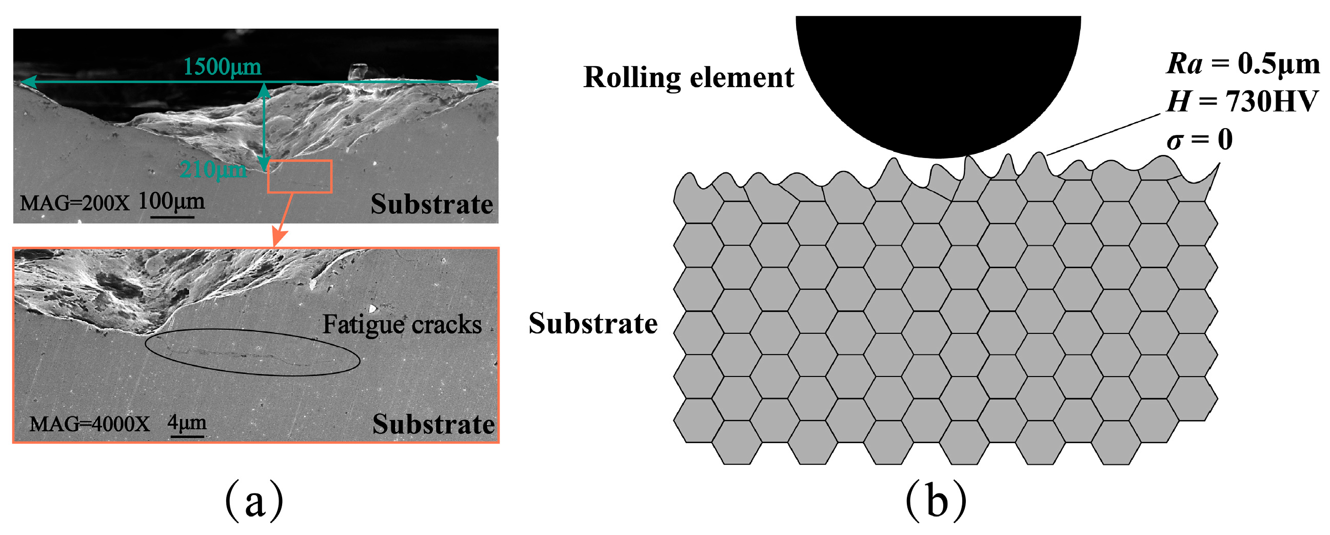
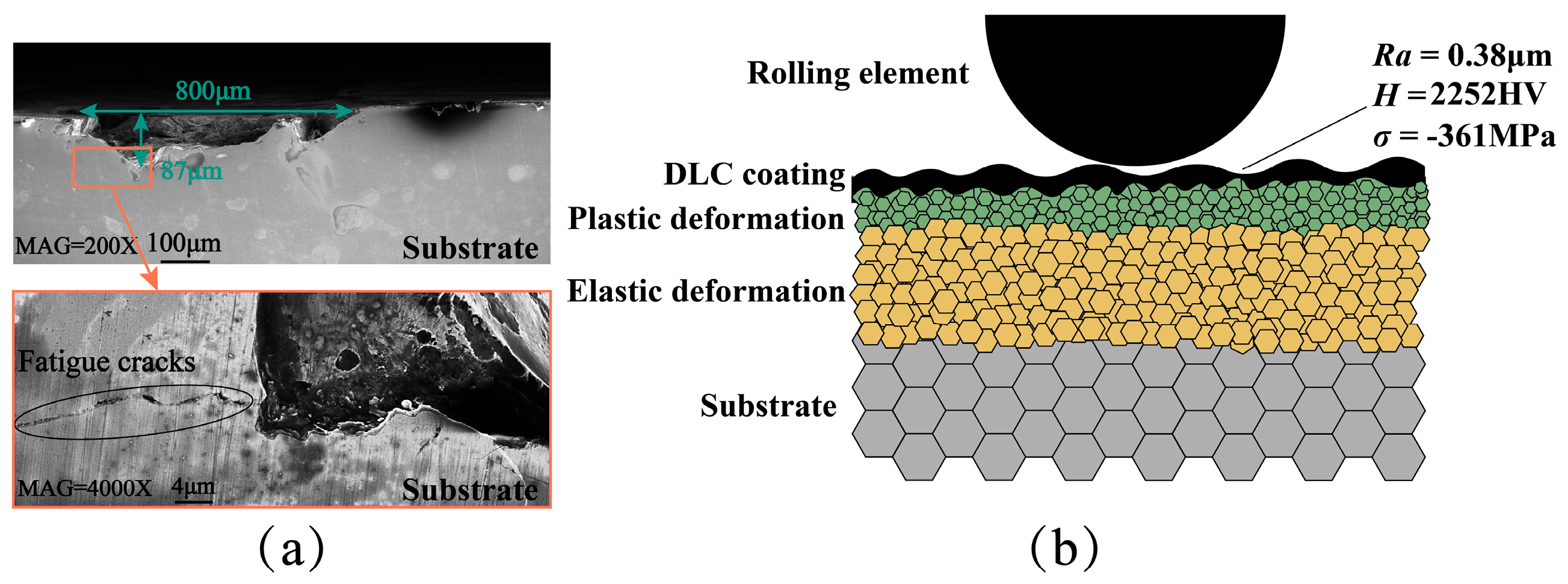
3.5. Analysis of Rolling Contact Fatigue Failure Mechanisms

Table 5 shows a data summary table. Using Table 5, we can accurately observe the differences in experimental data among each group of test specimens, which is conducive to understanding the correlation between the improvements in the surface properties of the test specimens caused by the USRP-composite DLC coating and the experimental results.
(1)
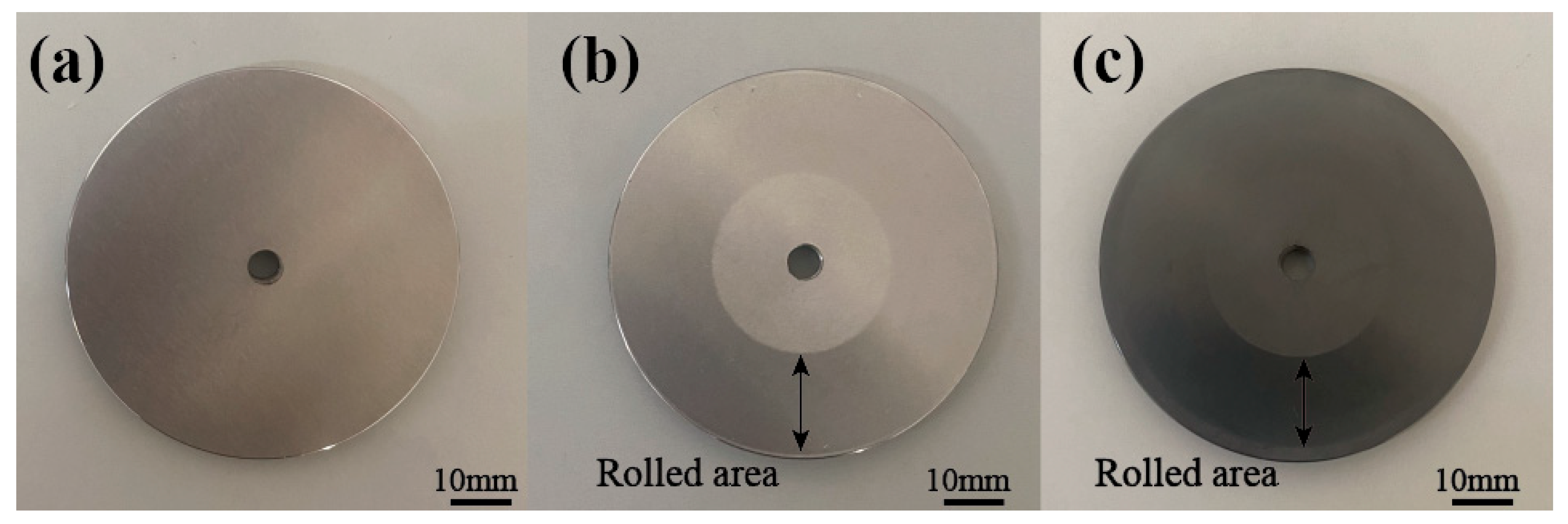
N (Fatigue Life: 1.79 × 10⁶ Cycles; Wear Volume: 25.5 × 1011 μm3).
Initial stage: The surface roughness of N (0.5 μm) leads to a small contact area between the rolling elements and the specimen, causing contact stresses to concentrate on the asperities of the specimen surface. Under load, plastic deformation of the asperities forms adhesive junctions, thereby inducing adhesive wear. Shear fracture of these junctions generates wear debris. At this stage, adhesive and abrasive wear mechanisms dominate. Due to the substrate hardness of only 730 HV, the debris embeds into the substrate, forming plowing grooves and plastic pile-up. Steady stage: Under cyclic loading, wear debris in the contact zone forms a lubricating layer containing FeO, Fe3O4, and carbide fragments, as the wear mode shifts to be dominated by abrasive and oxidative wear. Subsurface accumulated plastic deformation forms a work-hardened layer but fails to prevent fatigue crack initiation. Failure stage: Under cyclic loading, subsurface microcracks propagate into semi-elliptical shapes, reaching critical dimensions (5600 × 1500 × 210 μm3) to form spalling pits. The sudden reduction in contact area leads to an increase in local stress, causing the experiment to stop due to excessive vibration (Figure 14).
(2)
U (Fatigue Life: 3.36 × 10⁶ Cycles; Wear Volume: 5.4 × 1011 μm3).
Initial stage: After USRP treatment, the surface roughness of specimen U decreases from 0.5 μm to 0.22 μm, resulting in increased contact area and uniform stress distribution. Residual compressive stress suppresses plastic deformation of asperities, while the surface microhardness of 840 HV mitigates abrasive wear. At this stage, minor abrasive wear dominates. Steady stage: The gradient nanocrystalline layer and high-density dislocations formed by ultrasonic rolling enhance shear resistance. An oxide film at the contact interface isolates metal-to-metal contact, reducing adhesive wear. Residual compressive stress inhibits crack initiation. The wear mechanism transitions to abrasive and oxidative wear dominance. Failure stage: Under cyclic loading, fatigue damage saturates in the gradient hardened layer, and dislocation density decreases to substrate levels. Subsurface crack propagation forms a spalling pit (2500 × 1100 × 115 μm3). The sudden reduction in contact area leads to an increase in local stress, causing the experiment to stop due to excessive vibration (Figure 15).
(3)
UD (Fatigue Life: 6.55 × 10⁶ Cycles; Wear Volume: 3.73 × 1011 μm3).
The synergistic effect at the coating–substrate interface of UD presents unique tribological behavior. Initial stage: After DLC coating deposition, the surface roughness of the specimens increased from 0.22 μm to 0.38 μm, resulting in a decrease in the actual contact area between the specimens and the rolling elements, and mild wear at the coating interface is dominant, generating small-sized wear debris. Steady stage: The sp3/sp2 hybrid bonds of the DLC coating endow it with high hardness and a low friction coefficient. During the friction process, the sp3 bonds confer excellent hardness (2252HV) and wear resistance to the coating, while the sp2 bonds significantly reduce the friction coefficient and provide moderate toughness and self-lubricating properties [27,28]. The synergistic effect of the coating–substrate gradient structure and the dynamic transfer film constructs an efficient anti-wear system [29,30]. Under cyclic loading, a graphitized transfer film is generated at the contact interface through tribochemical reactions, which can effectively reduce the friction coefficient and inhibit adhesive wear. The high-hardness (840 HV) substrate provides mechanical support for the coating to avoid cracking due to stress deformation; the high residual compressive stress (−361 MPa) on the coating surface inhibits interface delamination and enhances the bonding strength and stability. In addition, the residual compressive stress inside the substrate can effectively inhibit the initiation of subsurface fatigue cracks, further enhancing the anti-wear performance. Failure stage: Synergistic degradation of coating–substrate interface fatigue damage and gradient structure triggers complex failure. Increasing cycle counts cause local delamination of the DLC coating, exposing the USRP-treated layer. Delaminated carbon fragments and Fe3O4 particles form abrasive clusters that plow parallel grooves in the contact zone, gradually developing cracks into spalling pits. The wear form changes to a combination of oxidative wear and abrasive wear, ultimately forming a 1200 × 800 × 87 μm3 spalling pit. The sudden reduction in contact area leads to an increase in local stress, causing the experiment to stop due to excessive vibration (Figure 16).

4. Conclusions

In this study, rolling contact fatigue life experiments were conducted on three groups of specimens: the untreated group, the group treated with ultrasonic surface rolling process (USRP), and the group treated with USRP-composite DLC coating. The following conclusions were drawn through characterization and analysis:
(1).
The USRP reduces the surface roughness of the specimens by 56% through the ultrasonic vibration and static pressure applied to the surface of each specimen. It also increases the surface hardness by 15.07% and introduces residual compressive stress with a depth of up to 0.6 mm. The maximum residual compressive stress, which is −569 MPa, occurs at a depth of 0.2 mm from the surface. By improving the surface properties of the substrate, USRP enhances coating–substrate adhesion by 26.24%.
(2).
Analysis of the rolling contact fatigue life experiment: The average rolling contact fatigue life of the specimens treated with USRP-composite DLC coating is 6.55 × 10⁶ cycles, which is 94.94% higher than that of the specimens treated only with USRP and 208.24% higher than that of the untreated specimens. In terms of wear characteristics, the USRP-composite DLC specimens have the smallest wear scars and spalling pits. The average wear volume of the USRP-composite DLC-coated specimens is 3.73 × 1011 μm3, which is 30.95% lower than that of USRP-treated specimens and 85.38% lower than that of untreated specimens.
(3).
Mechanism analysis: The USRP-composite DLC coating establishes a synergistic mechanism between the coating and substrate on the specimen surface: the DLC coating resists surface wear due to its high hardness and low friction coefficient, while the USRP treatment reduces substrate deformation and crack growth by decreasing surface roughness, increasing substrate hardness, and introducing residual compressive stress. Simultaneously, it enhances coating–substrate adhesion, collectively demonstrating exceptional wear resistance.
(4).
Due to the constraints of the research topic and experimental equipment, the influence of DLC coating deposition on the residual stress along the depth direction of the test specimens was not investigated, and the graphitization transfer film theory was not verified. Further exploration and verification will be conducted through experiments in subsequent research.

Author Contributions

Conceptualization, Y.W. and L.C.; methodology, Y.W.; software, Y.W. and L.C.; validation, Y.W.; formal analysis, Y.W. and L.C.; investigation, Y.W. and L.C.; resources, Y.W. and G.Z.; data curation, Y.W. and L.C.; writing—original draft preparation, L.C.; writing—review and editing, Y.W., S.X. and M.Z.; visualization, L.C.; supervision, Y.W. and S.X.; project administration, Y.W.; funding acquisition, Y.W. All authors have read and agreed to the published version of the manuscript.

Funding

This research was funded by the National Natural Science Foundation of China (No. 52075274); the Taishan Industrial Experts Program (No. tscx202312171); the Shandong Provincial Key Research and Development Program (Major Science and Technology Innovation Project) (No. 2022CXGC010304); and the Shandong Province Science and Technology Innovation Ability Improvement Project for Small and Medium-Sized Enterprises (No. 2023TSGC0356, 2023TSGC0374, 2024TSGC0961).

Institutional Review Board Statement

Not applicable.

Informed Consent Statement

Not applicable.

Data Availability Statement

Data are contained within the article.

Conflicts of Interest

Author Guanghui Zheng was employed by the company Shandong Jindi Precision Machinery Technology Co., Ltd. The remaining authors declare that the research was conducted in the absence of any commercial or financial relationships that could be construed as a potential conflict of interest.

References

  1. Machado de Azevedo, H.D.M.; Araújo, A.M.; Bouchonneau, N. A review of wind turbine bearing condition monitoring: State of the art and challenges. Renew. Sust. Energy Rev. 2016, 56, 368–379. [Google Scholar] [CrossRef]
  2. Cong, F.; Chen, J.; Dong, G.; Pecht, M. Vibration model of rolling element bearings in a rotor-bearing system for fault diagnosis. J. Sound Vib. 2013, 332, 2081–2097. [Google Scholar] [CrossRef]
  3. Rejitha, R.; Kesavan, D.; Chakravarthy, P.; Murty, S.V.S.N. Bearings for aerospace applications. Tribol. Int. 2023, 181, 108312. [Google Scholar] [CrossRef]
  4. Xu, F.; Ding, N.; Li, N.; Liu, L.; Hou, N.; Xu, N.; Guo, W.; Tian, L.; Xu, H.; Wu, C.; et al. A review of bearing failure Modes, mechanisms and causes. Eng. Fail. Anal. 2023, 152, 107518. [Google Scholar] [CrossRef]
  5. Ohno, N.; Komiya, H.; Mia, S.; Morita, S.; Satoh, N.; Obara, S. Bearing fatigue life tests in advanced base oil and grease for space applications. Tribol. Trans. 2008, 52, 114–120. [Google Scholar] [CrossRef]
  6. Shi, G.; Yu, X.; Meng, H.; Zhao, F.; Wang, J.; Jiao, J.; Jiang, H. Effect of surface modification on friction characteristics of sliding bearings: A review. Tribol. Int. 2023, 177, 107937. [Google Scholar] [CrossRef]
  7. Du, F.; Li, D.; Sa, X.; Li, C.; Yu, Y.; Li, C.; Wang, J.; Wang, W. Overview of friction and wear performance of sliding bearings. Coatings 2022, 12, 1303. [Google Scholar] [CrossRef]
  8. El-Thalji, I.; Jantunen, E. Dynamic modelling of wear evolution in rolling bearings. Tribol. Int. 2015, 84, 90–99. [Google Scholar] [CrossRef]
  9. Dang, X.; Liang, X.; Luo, S.; Li, Y.; Jiao, Y.; Tian, Z.; He, W. Surface strengthening and fatigue life improvement of single crystal Ni-based superalloys via laser shock peening without coating. Mater. Design 2023, 232, 112097. [Google Scholar] [CrossRef]
  10. Qiu, Y.; Peng, Y.; Zuo, Y. Ultrasonic impact surface strengthening treatment and fatigue behaviors of titanium alloy thin-walled open hole components. Eng. Fract. Mech. 2024, 307, 110292. [Google Scholar] [CrossRef]
  11. Li, W.; Wang, S.; Yang, X.; Duan, H.; Wang, Y.; Yang, Z. Research Progress on Fatigue Damage and Surface Strengthening Technology of Titanium Alloys for Aerospace Applications. Metals 2025, 15, 192. [Google Scholar] [CrossRef]
  12. Dang, J.; An, Q.; Lian, G.; Zou, Z.; Li, Y.; Wang, H.; Chen, M. Surface modification and its effect on the tensile and fatigue properties of 300M steel subjected to ultrasonic surface rolling process. Surf. Coat. Technol. 2021, 422, 127566. [Google Scholar] [CrossRef]
  13. Zhang, K.M.; Liu, S.; Wang, J.; Sun, Z.X.; Liu, W.J.; Zhang, C.C.; Zhang, X.C. Effect of high-frequency dynamic characteristics in the ultrasonic surface rolling process on the surface properties. J. Mater. Process. Tech. 2024, 327, 118353. [Google Scholar] [CrossRef]
  14. Lu, L.X.; Sun, J.; Li, L.; Xiong, Q.C. Study on surface characteristics of 7050-T7451 aluminum alloy by ultrasonic surface rolling process. Int. J. Adv. Manuf. Technol. 2016, 87, 2533–2539. [Google Scholar] [CrossRef]
  15. Wu, J.; Deng, J.; Lu, Y.; Zhang, Z.; Meng, Y.; Wang, R.; Sun, Q. Effect of textures fabricated by ultrasonic surface rolling on dry friction and wear properties of GCr15 steel. J. Manuf. Process. 2022, 84, 798–814. [Google Scholar] [CrossRef]
  16. Zhang, Y.L.; Lai, F.Q.; Qu, S.G.; Liu, H.P.; Jia, D.S.; Du, S.F. Effect of ultrasonic surface rolling on microstructure and rolling contact fatigue behavior of 17Cr2Ni2MoVNb steel. Surf. Coat. Technol. 2019, 366, 321–330. [Google Scholar] [CrossRef]
  17. Rajak, D.K.; Kumar, A.; Behera, A.; Menezes, P.L. Diamond-like carbon (DLC) coatings: Classification, properties, and applications. Appl. Sci. 2021, 11, 4445. [Google Scholar] [CrossRef]
  18. Mou, C.; Liu, Z.; Zhu, G.; Zhang, G.; Cao, X. Study on impact wear and damage mechanisms of DLC films on TC4 and 9Cr18 alloys. Diam. Relat. Mater. 2024, 148, 111390. [Google Scholar] [CrossRef]
  19. Milewski, K.; Madej, M. Diamond-like carbon (DLC) coatings on roller bearing elements of belt conveyors. Metalurgija 2022, 61, 835–837. [Google Scholar]
  20. Ye, T.; Ma, J.; Jia, Z.; Li, T.; Liu, W.; Yu, W. Microstructure, mechanical properties and low-temperature tribological behavior of Cr/Cr-W/W-DLC/DLC multilayer coatings on 5A06 Al alloy. J. Mater. Res. Technol. 2022, 18, 810–819. [Google Scholar] [CrossRef]
  21. Duan, C.; Qu, S.; Hu, X.; Jia, S.; Li, X. Evaluation of the influencing factors of combined surface modification on the rolling contact fatigue performance and crack growth of AISI 52100 steel. Wear 2022, 494, 204252. [Google Scholar] [CrossRef]
  22. Tillmann, W.; Dias, N.F.L.; Stangier, D. Influence of plasma nitriding pretreatments on the tribo-mechanical properties of DLC coatings sputtered on AISI H11. Surf. Coat. Technol. 2019, 357, 1027–1036. [Google Scholar] [CrossRef]
  23. JB/T 10510-2005; Test Method for Contact Fatigue of Rolling Bearing Material. National Library of Standards: Beijing, China, 2005.
  24. Salvadori, M.C.; Martins, D.R.; Cattani, M. DLC coating roughness as a function of film thickness. Surf. Coat. Technol. 2006, 200, 5119–5122. [Google Scholar] [CrossRef]
  25. Holmberg, K.; Ronkainen, H.; Laukkanen, A.; Wallin, K.; Hogmark, S.; Jacobson, S.; Wiklund, U.; Souza, R.M.; Ståhle, P. Residual stresses in TiN, DLC and MoS2 coated surfaces with regard to their tribological fracture behaviour. Wear 2009, 267, 2142–2156. [Google Scholar] [CrossRef]
  26. Xiao, Y.; Shi, W.; Han, Z.; Luo, J.; Xu, L. Residual stress and its effect on failure in a DLC coating on a steel substrate with rough surfaces. Diam. Relat. Mater. 2016, 66, 23–35. [Google Scholar] [CrossRef]
  27. Grill, A. Review of the tribology of diamond-like carbon. Wear 1993, 168, 143–153. [Google Scholar] [CrossRef]
  28. Martins, P.S.; Carneiro, J.R.G.; Ba, E.C.T.; Vieira, V.F.; Amaral, D.B.; Cruz, N.C. Study on the tribological behavior of wear and friction coefficient on AISI M35 high-speed steel with and without DLC coating. Mater. Res. 2021, 25, e20200577. [Google Scholar] [CrossRef]
  29. Liu, Y.; Erdemir, A.; Meletis, E.I. A study of the wear mechanism of diamond-like carbon films. Surf. Coat. Technol. 1996, 82, 48–56. [Google Scholar] [CrossRef]
  30. He, W.; Ahmat, M.; Zhou, H.; Li, Z.; Qiu, W.; Li, D. Influence of diamond-like carbon coatings and micro-texturing on friction and wear of seal interfaces: Experiment and simulation study. Proc. Inst. Mech. Eng. Part E J. Process Mech. Eng. 2024, 09544089241226632. [Google Scholar] [CrossRef]
Figure 1. Experimental materials: (a) thrust bearing ring; (b) rolling elements; (c) cage; (d) GCr15 bearing steel specimen.
Coatings 15 00616 g001
Figure 2. Schematic diagram of the ultrasonic surface rolling processing system.
Coatings 15 00616 g002
Figure 3. Schematic diagram of rolling fatigue test.
Coatings 15 00616 g003
Figure 4. Optical micrographs of specimens: (a) N; (b) U; (c) UD.
Coatings 15 00616 g004
Figure 5. Surface roughness of specimens.
Coatings 15 00616 g005
Figure 6. 3D Topographies of specimen surfaces: (a) N; (b) U; (c) UD.
Coatings 15 00616 g006
Figure 7. Cross-sectional profiles of N, U, and UD.
Coatings 15 00616 g007
Figure 8. Cross-sectional SEM images: (a) without USRP-composite DLC coating; (b) with USRP-composite DLC coating.
Coatings 15 00616 g008
Figure 9. Surface hardness of N, U, and UD.
Coatings 15 00616 g009
Figure 10. Depth-direction residual stress of N and U.
Coatings 15 00616 g010
Figure 11. Scratch model, optical micrographs of scratches with acoustic signal curves, and penetration depth curves: (a) scratch model; (b) USRP-untreated composite DLC coating; (c) USRP-treated composite DLC coating.
Coatings 15 00616 g011
Figure 12. Rolling contact fatigue life and wear volume for N, U, and UD.
Coatings 15 00616 g012
Figure 13. Comparison of wear scars and maximum spalling sizes after rolling contact fatigue test: (a) wear scar and cross-sectional profile of N; (b) wear scar and cross-sectional profile of U; (c) wear scar and cross-sectional profile of UD; (d) comparison of maximum spalling sizes among N, U, and UD.
Coatings 15 00616 g013
Figure 14. Friction mechanism and SEM of maximum spalling cross-section for Group N: (a) SEM of maximum spalling cross-section; (b) friction mechanism.
Coatings 15 00616 g014
Figure 15. Friction mechanism and SEM of maximum spalling cross-section for Group U: (a) SEM of maximum spalling cross-section; (b) friction mechanism.
Coatings 15 00616 g015
Figure 16. Friction mechanism and SEM of maximum spalling cross-section for Group UD: (a) SEM of maximum spalling cross-section; (b) friction mechanism.
Coatings 15 00616 g016
Table 1. Physical property parameters of GCr15 bearing steel.
Density (kg/m3)Elastic Modulus (GPa)Poisson′s RatioThermal Conductivity (W/m·K)Specific Heat Capacity (J/kg·K)
78302190.344460
Table 2. Parameters of NTN 51305 single-direction thrust ball bearing.
CategoryParameterCategoryParameter
Bearing Outer Diameter (mm)52Rolling Element Diameter (mm)9.525
Bearing Inner Diameter (mm)25Basic Dynamic Load Rating (KN)35.5
Bearing Thickness (mm)18Basic Static Load Rating (KN)61.5
Number of Rolling Elements3Limiting Speed with Oil Lubrication (r/min)4900
Table 3. Results of rolling contact fatigue life.
Number of GroupsNUUD
11 × 1062.15 × 1065 × 106
21.6 × 1063 × 1065.5 × 106
31.8 × 1063.35 × 1066.6 × 106
42.2 × 1064 × 1067.5 × 106
52.35 × 1064.3 × 1068.15 × 106
Table 4. Analysis of variance (ANOVA) for rolling contact fatigue life.
Source of VariationSSdfMSFPF(2,12)
Between Groups58.831229.41632.0970.0000153.89
Within Groups10.999120.917
Total69.8314
Table 5. Data summary.
GroupRa/μmMicrohardness/HVSurface Residual Stress/MPaRCF/E6CV for RCFWear Volume
/E11 μm3
Length
(Max Spalling)
/μm
Width
(Max Spalling)
/μm
Depth
(Max Spalling)
/μm
N0.5 ± 0.08730 ± 120 ± 251.79 ± 0.4826.73%25.5 ± 45600 ± 12201500 ± 220210 ± 84
U0.22 ± 0.03840 ± 15−347 ± 273.36 ± 0.7622.62%5.4 ± 0.672500 ± 10301100 ± 167115 ± 56
UD0.38 ± 0.052252 ± 29−361 ± 256.55 ± 1.1818.02%3.73 ± 0.381200 ± 670800 ± 9287 ± 40
Disclaimer/Publisher’s Note: The statements, opinions and data contained in all publications are solely those of the individual author(s) and contributor(s) and not of MDPI and/or the editor(s). MDPI and/or the editor(s) disclaim responsibility for any injury to people or property resulting from any ideas, methods, instructions or products referred to in the content.

