Article

Magnetoplasmonic Resonators Designed with Hexagonally Arrayed Au/BIG Bilayer Nanodisks on Au Thin Film Layers for Enhanced MOKE and Refractive Index Sensing

1
Center for Modern Physics Technology, School of Mathematics and Physics, University of Science and Technology Beijing, Beijing 100083, China
2
Key Laboratory of Pulsed Power Translational Medicine of Zhejiang Province, Hangzhou Ruidi Biotechnology Company Ltd., Room 803, Bldg. 4, 4959 Yuhangtang Road, Cangqian Street, Hangzhou 310023, China
3
Zhengzhou Tianzhao Biomedical Technology Company, Ltd., 7 Dongqing Street, Zhengzhou High Tech Development Zone, Zhengzhou 451450, China
*
Author to whom correspondence should be addressed.
These authors contributed equally to this work.
Coatings 2025, 15(5), 601; https://doi.org/10.3390/coatings15050601 (registering DOI)
Submission received: 6 April 2025 / Revised: 30 April 2025 / Accepted: 16 May 2025 / Published: 18 May 2025

Abstract

:
A kind of magnetoplasmonic resonators is numerically designed with hexagonally arrayed Au/bismuth iron garnet (BIG) bilayer nanodiscks on Au thin film layers. Multi-physics coupling calculation on their magnetoplasmonic resonance features suggest that there exists a strong resonant coupling between the surface plasmon excited by the hexagonal grating and the waveguide modes induced by Au-BIG-Au, which can significantly enhance the transverse magneto-optical Kerr effect. Interestingly, a new type of circular oscillating can be induced in the optical-transparent BIG layers as the thickness of BIG layers is between 2 nm and 22 nm. This circular oscillating exhibits a distinct thickness-dependent feature, which can be attributed to the near field interference of the excited localized plasmon resonance between the two interfaces formed by the middle BIG nanodiscs in the top Au nanodisks and the bottom Au thin film layers according to the simulation. These unique magnetoplasmonic features endow this kind of magnetoplasmonic resonators with a greatly enhanced refractive index sensing property, with a calculated figure of merit (FOM) value of up to 7527 RIU−1.

1. Introduction

Magneto-optical (MO) effect refers to the phenomenon that the propagation characteristics of a beam of light change after transmission or reflection by a magnetic material. The MO effect that provides light intensity modulation manifests as the transverse magneto-optical Kerr effect (TMOKE). The TMOKE can be observed when p-polarized light is incident obliquely on the surface of a magnetic medium, with the magnetization perpendicular to the incident surface and parallel to the surface of the medium. The TMOKE in the smooth films of ferromagnetic metals such as iron and nickel, however, exhibits a weak magnitude [1,2]. Surface plasmon resonance (SPR) can be introduced to enhance the TMOKE [3,4,5,6,7,8]. Meanwhile, the signal with magnetic field modulation has a narrower full width at half maximum (FWHM) than the SPR signal [9,10]. Based on this principle, numerous researchers have developed high-performance MO-SPR sensors, some of which have been successfully utilized as probing elements for manufacturing novel MO-SPR sensors [11,12,13,14].
Compared with traditional ferromagnetic metals, rare-earth-doped garnet films (such as bismuth iron garnet, Bi3Fe5O12 (BIG)) have a potential advantage in optical modulation applications due to the strong spin-orbit coupling of Bi, which enhances the magneto-optical effect and has a very low optical loss in the visible range [15,16,17]. In this paper, a type of magnetoplasmonic resonator composed of Au/BIG bilayer nanodisks hexagonally arrayed on the top of an optically thick Au film is proposed to measure the reflectance changes after the interaction between light and the structures, whose TMOKE features are calculated using OMSOL6.0 Multiphysics. The thickness of BIG in the designed structure during the simulation here is designed from one nanometer to tens of nanometers, which is experimentally possible and facilitate the miniaturization and integration of devices. Simulation results suggest that the TMOKE effect of this kind of magnetoplasmonic resonators can be enhanced through the resonant coupling of surface plasmon polariton (SPP) and guided modes. An ultra-narrow Fano-like linear feature in the TMOKE signal is observed, characterized by a FWHM of 0.097 nm. Particularly, periodic circular oscillating polariton waves are also observed in BIG nanodisks. Further study indicates that this kind of structure exhibits much higher sensitivity to variations of the environmental refractive index.

2. Theoretical Analysis

The designed structure of the magnetoplasmonic resonators is illustrated in Figure 1. Au/BIG double-layered nanodisks are hexagonally arrayed over a 150 nm thick Au layer on the glass substrate. The bottom Au layer can reduce light loss, increase the energy of the local light field, and narrow the spectral bandwidth [4]. In addition, the chemical stability and corrosion resistance of Au make it a preferable choice for future sensing applications. The oblique incidence of p-polarized light on the structure can induce the SPR of Au at the hexagonally arrayed nanostructure, leading to a significant enhancement of the electromagnetic field in the sensing layer region. The applied magnetic field is perpendicular to the incident light plane (x–z plane), and when the magnetic field is reversed, the magnetization of magnetic materials causes non-reciprocal changes in the SPR wave vector [18], resulting in changes in reflectivity and TMOKE signals.
In the reflection mode, TMOKE can be quantified as follows:
  T M O K E = R + H R H R + H + R H
The reflectance of p-polarized light under positive and negative magnetic fields is denoted as R + H and R H , respectively. When the applied magnetic field is perpendicular to the incident light plane, the SPR wave vector can be expressed as follows:
  k s p p = k s p p 0 + k m o ± M
where k s p p 0 is the wave vector of SPR when no magnetic field is applied, and k m o ± M is the correction of the SPR wave vector after magnetization of the magnetic medium when the magnetic field is applied perpendicular to the incident light plane. The incident light wave vector must satisfy the phase matching condition due to the SPR wave vector exceeding the incident wave vector. For a hexagonal arrangement, the periodic conditions for exciting SPR can be expressed as follows [19]:
k s p p 2 = k x + m b 1 2 + k y + n b 2 2
where kx and ky are the wave vectors of x and y components of the incident light, respectively. The diffraction series is denoted by m and n, while the inverse lattice basis vectors are represented by b1 and b2 ( b 1 = 2 π P i + 2 π 3 P j , b 2 = 4 π 3 P j ). The excitation of SPR is contingent upon both the incident wave vector and the structural parameters. Based on the afore-mentioned equations, we fixed the period P = 300 3   n m , the incidence angle of θ = 20 ° , and diffraction orders m = 1 , n = 0 . (The sensing design scheme adopted in this paper is wavelength modulation). The Drude model is employed to describe the dielectric constant ε 1 of gold, see Figure S1 [20]. The magnetization direction in the coordinate system depicted in Figure 1 aligns with the Y-axis, and the dielectric tensor of the BIG layer can be mathematically represented as follows:
  ε B I G = ε x x 0 i g 0 ε y y 0 i g 0 ε z z
where ε x x = ε y y = ε z z , ε x x and g are taken from Ref. [6]. The variation of the applied magnetic field is manifested by altering the non-diagonal elements of the dielectric tensor. The wave optical module of the COMSOL Multiphysics software (6.0) was utilized for numerical simulation (the grid configuration utilizes a “physical field control grid” and the cell size is “refinement”).

3. Results and Discussion

The maximum TMOKE signal was achieved with the optimized structure of D = 248   n m , t 1 = 30   n m , and t 2 = 10   n m . The obtained reflection curve and TMOKE signal are shown in Figure 2a. There is an obvious extinction phenomenon at 607.8   n m , accompanied by a corresponding Fano-shaped line in the TMOKE signal. To visually illustrate the physical mechanism, the electric field mode E distributions of the structure in the x–z plane and in the x–y plane 1 nm above the structure surface are presented in Figure 2b,c, respectively, under the incident light with a wavelength of 607.8   n m .
Since the structure satisfies Equation (3), the interaction between incident light and gold excites propagating SPR, while the individual nanodisks simultaneous generate continuous broadband localized surface plasmon resonance (LSPR) [21]. The coupling of LSPR of Au nanodisks and SPR from the bottom Au layer greatly enhances the electromagnetic field at the interface.
Amazingly, an interesting phenomenon was observed: a ring-shaped oscillating electromagnetic wave appearing inside the BIG nanodisks. Figure 2d shows the distribution of |E| in a single nanodisk in the x–y plane at 1 nm above the gold thin film layers, which corresponds to the alternating bright parts and dark parts in the BIG nanodisks in Figure 2b, similar as the annular interference fringes in the Newton’s rings. The Au/BIG nanodisks on the Au substrate can be regarded as a metal–dielectric–metal (MDM) resonator structure. When the dispersion equation is satisfied [22], it excites the waveguide mode with minimal energy loss. The plasma waveguide is excited at the upper and lower interfaces of BIG and gold, respectively, and is bound in the nanocavity that is similar as magnetic optical resonators. It propagates from the edge of the nanodisk to the inside and oscillates between the two interfaces formed among BIG nanodisks, Au nanodisks and Au thin film layers, leading to the interference in the BIG nanodisk around their centers. Consequently, the brightest ring-like pattern in the center is generated in the distribution diagram of |E|. The plasmonic waveguide in the nanocavity effectively enhances the coupling of SPR between the two sides of the gold layers, which can potentially improve the local reinforcement capability of the structure on the electromagnetic field and augmenting the interaction volume between the analyte and optical field.
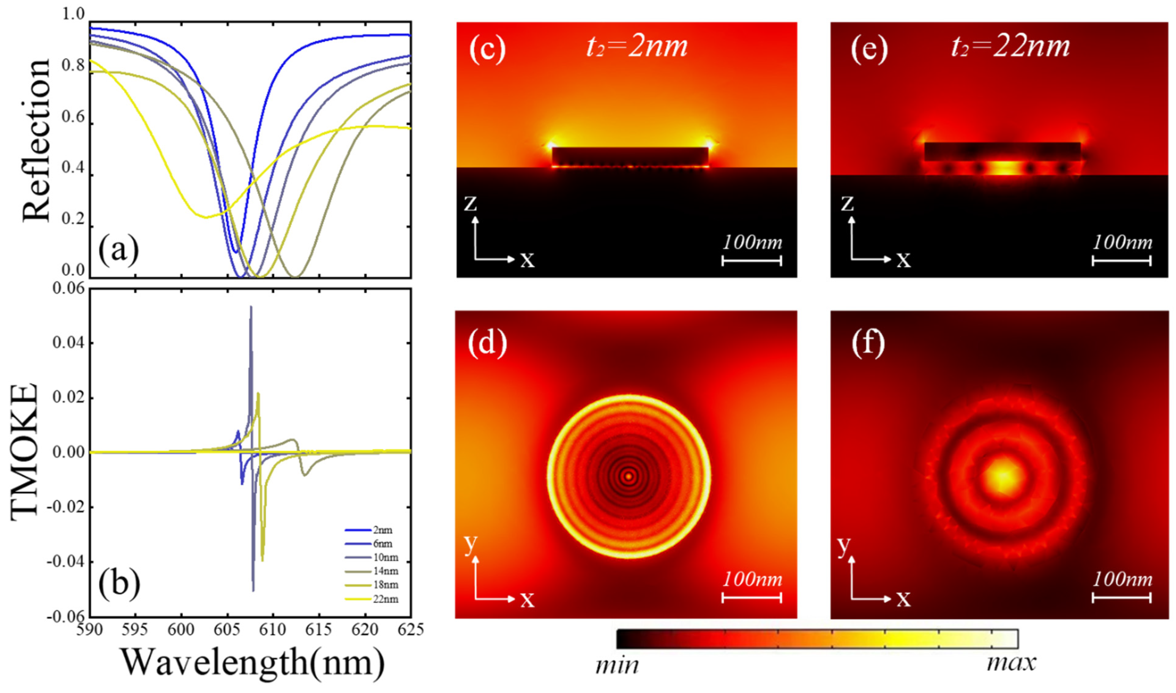
The TMOKE signal is highly influenced by the structural geometry. The reflection of a demagnetized BIG sample (M = 0) as a function of wavelength at various BIG thicknesses t 2 is illustrated in Figure 3a. The simulation will be focused on the wavelength range from 590   n m to 625   n m . Figure 3b illustrates the TMOKE signal, wherein the position and amplitude of the Fano-like feature exhibit high sensitivity to variations in the thickness of the magnetic layer. As the BIG thickness increased from 2 nm to 22 nm, the Fano-shaped characteristic became increasingly pronounced, reaching maximum prominence at a BIG thickness of 10   n m . Notably, the TMOKE response peak value reached approximately 0.05045 at 10   n m BIG thickness, significantly exceeding the corresponding values of 0.000945 and 0.0286 observed at BIG thicknesses of 2 nm and 20   n m , respectively. Theoretically, the outcomes are influenced by two key factors. One is the optical loss of the structure [4], and the other is the oscillation of the waveguide mode within BIG [22]. The relationship between the waveguide layer thickness and effective refractive index ( n e f f ) in MDM waveguide modes can be described through the mode characteristic equations: tan β d / 2 = β 2 k 0 2 n M 2 / k 0 2 n D 2 β 2 , where β is the propagation constant ( β = k 0 n e f f ) and k 0 = 2 π / λ . Our analysis reveals that increasing the waveguide layer (BIG) thickness enables support for higher-order modes, with the n e f f asymptotically approaching the core refractive index. Conversely, as the thickness decreases, the n e f f reduces accordingly until reaching the cutoff condition. Figure 3c,d show the |E| distribution in BIG at t 2   = 2   n m , and the wavelength of the oscillatory wave is calculated as 15   n m . Although the circular oscillatory waves still exist in it, their internal oscillation is weakened due to the much-reduced BIG layer thickness. Figure 3e,f give the |E| distribution in BIG at t 2   = 22   n m , and the corresponding wavelength of the oscillatory waves is calculated as 130   n m . The calculated results suggest that the optical loss of this type of structure greatly increases as the BIG thickness is increased to 22   n m . Simultaneously, the waveguide mode inside BIG and the propagating SPR at the gold-air interface can be dramatically weakened. Thus, the reflectivity valley becomes shallow, and the TMOKE signal disappears. Clearly, combination of the annular interference fringes similar as those in the Newton’s rings observed in Figure 2b–d and Figure 3c–f, one new type of the near-field equal thickness interference at nanoscale can be defined, which can be induced by the coupling of the waveguide mode and the propagating SPR inside BIG nanodisks. This new kind of near field interference can theoretically enhance the TMOKE greatly.
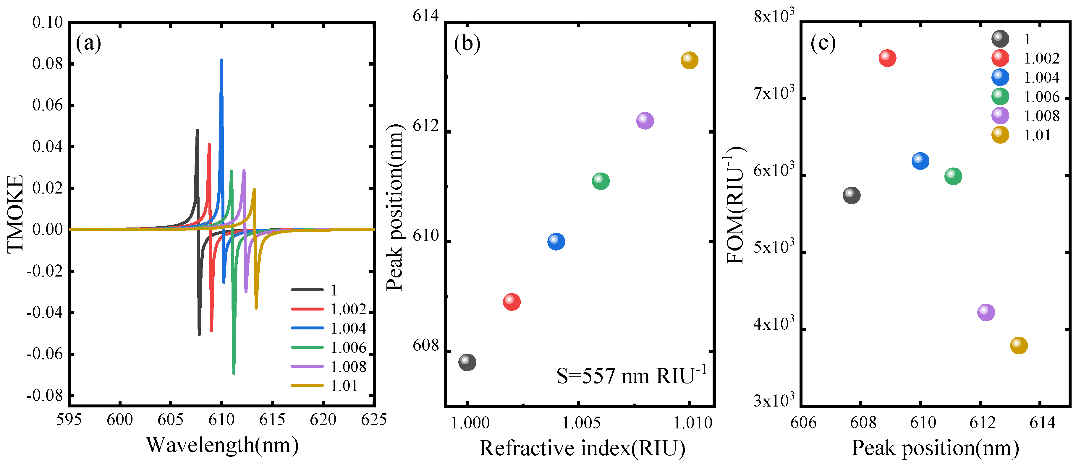
One important application of this type of magnetoplasmonic resonator is ultrasensitive gas sensing. For this goal, the correlation between the TMOKE signal and the refractive index of analytes surrounding the structure is simulated. Figure 4a illustrates the changes in TMOKE values under different analyte refractive indices. Figure 4b gives the change in the position of the Fano-like feature with the refractive index, showing a perfect linear relationship between the resonance position and the refractive index. The refractive index sensitivity, denoted as S = λ / Δ n i , is calculated by measuring the shift of the Fano-shaped feature λ and the corresponding change in refractive index of the surrounding medium Δ n i . Following the fitting analysis, a sensitivity value of S   = 557   n m / R I U is obtained for this structure. The performance value F O M , defined as F O M = S / Γ , is another crucial parameter for assessing sensor performance. To enhance the performance of the sensor, the FOM can be optimized through dual approaches: (1) intensifying interfacial electric fields via resonant mode to boost surface sensitivity, and (2) implementing magnetic field modulation schemes to narrow the FWHM of the response signal. For obtaining Γ accurately, the TMOKE signal is fitted as a function of wavelength λ to the Fano line shape [10]: T M O K E λ = A + B q Γ / 2 + λ λ 0 2 Γ / 2 2 + λ λ 0 2 ,. The line width, denoted as Γ , is determined by the resonant wavelength   λ 0 , the Fano parameter q , the fitting values of background A , and the total peak height B . Figure 4c illustrates FOM. Based on these definitions, our structure enables extraction of FOM reaching magnitudes in the thousands, up to 7527   R I U 1 . Similar structures have been studied in recent years, and their structures and FOMs are listed in Table 1. Clearly, the FOM value of the bilayer Au/BIG nanodisk arrays designed in this study is better than the highest one (6000 RIU−1) published currently.

4. Conclusions

To summarize, the mmagnetoplasmonic features of the magnetoplasmonic resonators designed with hexagonally arrayed Au/BIG bilayer nanodisks on Au thin film layers were investigated. This structure effectively enhanced the TMOKE effect by generating a complex resonance mode involving SPR and waveguide phenomena. The proposed nanostructures in the new type of magnetoplasmonic resonators could produce distinct, periodic, circularly oscillating plasmon waves in the BIG nanodisks, similar as the annular interference fringes in the Newton’s rings, which can be defined as one new type of the near-field equal thickness interference at nanoscale induced by the coupling of the waveguide mode and the propagating SPR inside BIG nanodisks. This new kind of near field interference can theoretically enhance the TMOKE signal and the performance of the proposed MO-SPR sensors dramatically. The resulted TMOKE signals by these magnetoplasmonic resonators exhibited a distinctive Fano shape, displaying an enhanced sensitivity to the refractive index changes of the surrounding medium. Consequently, both high sensitivity and FOM can be achieved simultaneously.
The simulation results encourage our team to prepare this type of hexagonally arranged periodic nanostructure by tackling the problem of transferring the BIG nanodisk-arrayed layer to the Au substrate using template-assisted nanolithography [25]. Regarding the difficulty in preparing BIG films, we can adopt the gradient meteorological deposition method. YIG (yttrium iron garnet) was used as a seed layer to promote the crystallization of BIG in high-temperature environments [25,26,27].

Supplementary Materials

Following supporting information can be downloaded at: https://www.mdpi.com/article/10.3390/coatings15050601/s1, Figure S1. The refractive index dispersion curve of the gold film.

Author Contributions

Conceptualization, Y.S.; Methodology, Y.S.; Software, Y.S.; Validation, X.C. and Z.W.; Resources, Y.S.; Writing—original draft, X.C. and Z.W.; Writing—review & editing, Y.S. and Z.W.; Visualization, Z.W. and X.C.; Supervision, Y.S.; Project administration, Y.S.; Funding acquisition, Y.S. All authors have read and agreed to the published version of the manuscript.

Funding

This study was financially supported by the National Natural Science Foundation of China (No. 52471259 and 51971029), the BRICS STI Framework Program by NSFC (No. 51861145309), the National S&T Major Project of China (No. 2018ZX10301201), the development of a highly sensitive magneto-optical biomolecular sensor experimental prototype (No. in USTB: 2019-0649),) and the probability analysis of nanoknife-coupling nanomedicine for combined anticancer therapy from Zhejiang Key Laboratory for Pulsed Power Translational Medicine through Hangzhou Ruidi Biotechnology Co., Ltd. (Hangzhou, China), and the 1125 Zhihui Zhengzhou Talent Project of Henan Province (No. in USTB: 39080070) from Zhengzhou Tianzhao Biomedical Technology Co. Ltd. (Zhengzhou, China).

Institutional Review Board Statement

Not applicable.

Informed Consent Statement

Not applicable.

Data Availability Statement

The data that support the findings of this study are available from the corresponding author upon reasonable request.

Conflicts of Interest

Yujun Song was partially employed by the Key Laboratory of Pulsed Power Translational Medicine of Zhejiang Province supported by Hangzhou Ruidi Biotechnology Company Ltd., also partially employed by Zhengzhou Tianzhao Biomedical Technology Company, Ltd. during this study. The remaining authors declare that the research was conducted in the absence of any commercial or financial relationships that could be construed as a potential conflict of interest.

References

  1. Krinchik, G.S.; Artem’Ev, V.A. Magneto-optical Properties of Ni, Co, and Fe in the Ultraviolet Visible and Infrared Parts of the Spectrum. J. Exp. Theor. Phys. 1968, 6, 1080–1085. [Google Scholar]
  2. Temnov, V.V. Ultrafast acousto-magneto-plasmonics. Nat. Photon 2012, 6, 728–736. [Google Scholar] [CrossRef]
  3. Caballero, B.; Garci, A.; Cuevas, J.C. Hybrid Magnetoplasmonic Crystals Boost the Performance of Nanohole Arrays as Plasmonic Sensors. ACS Photonics 2016, 3, 203–208. [Google Scholar] [CrossRef]
  4. Li, L.; Zong, X.; Liu, Y. All-metallic metasurfaces towards high-performance magneto-plasmonic sensing devices. Photonics Res. 2020, 8, 1742–1748. [Google Scholar] [CrossRef]
  5. Lou, P.; Wu, Q.; Zhang, C.; Wang, Z.; Song, Y. Enhanced magneto-optical Kerr effect via the synergistic effect of surface plasmon resonance and spin–orbit coupling in Au@Pt nanohybrid layers. J. Phys. D Appl. Phys. 2023, 56, 375001. [Google Scholar] [CrossRef]
  6. Belotelov, V.I.; Akimov, I.A.; Pohl, M.; Kotov, V.A.; Kasture, S.; Vengurlekar, A.S.; Gopal, A.V.; Yakovlev, D.R.; Zvezdin, A.K.; Bayer, M. Enhanced magneto-optical effects in magnetoplasmonic crystals. Nat. Nanotechnol. 2011, 6, 370–376. [Google Scholar] [CrossRef] [PubMed]
  7. Zhang, C.; Cui, X.; Zhang, W.; Zhu, R.; Song, Y. Numerical design of surface magneto-plasmon sensors of Au/Co double-layer square arrayed nanopores on the continuous gold thin film. J. Appl. Phys. 2023, 134, 024301. [Google Scholar] [CrossRef]
  8. Li, L.; Du, L.; Zong, X.; Liu, Y. VIS-NIR TMOKE enhanced dielectric-metal hybrid structure for high performance dual-channel sensing. Opt. Express 2023, 31, 35880–35891. [Google Scholar] [CrossRef]
  9. Chai, H.; Lu, Y.; Zhang, W. Enhancement of transverse magneto-optical Kerr effects and high sensing performance in a trilayer structure with nanopore arrays. Results Phys. 2021, 31, 105049. [Google Scholar] [CrossRef]
  10. Miroshnichenko, A.E.; Flach, S.; Kivshar, Y.S. Fano resonances in nanoscale structures. Rev. Mod. Phys. 2009, 82, 2257–2298. [Google Scholar] [CrossRef]
  11. Regatos, D.; Sepúlveda, B.; Fariña, D.; Carrascosa, L.G.; Lechuga, L.M. Suitable combination of noble/ferromagnetic metal multilayers for enhanced magneto-plasmonic biosensing. Opt. Express 2011, 19, 8336–8346. [Google Scholar] [CrossRef] [PubMed]
  12. Moncada-Villa, E.; Oliveira, O.N.; Mejía-Salazar, J.R. ε-Near-Zero Materials for Highly Miniaturizable Magnetoplasmonic Sensing Devices. J. Phys. Chem. C 2019, 123, 3790–3794. [Google Scholar] [CrossRef]
  13. Manera, M.; Rella, R. Improved gas sensing performances in SPR sensors by transducers activation. Sens. Actuators B Chem. 2013, 179, 175–186. [Google Scholar] [CrossRef]
  14. Okuda, T.; Koshizuka, N.; Hayashi, K.; Taniguchi, H.; Yamamoto, H. Synthesis of New Magnetooptical Material, Bismuth Iron Garnet. IEEE Transl. J. Magn. Jpn. 1988, 3, 483–484. [Google Scholar] [CrossRef]
  15. Popova, L.M.H.N.E. Magnetic properties of the magnetophotonic crystal based on bismuth iron garnet. Appl. Phys. 2012, 112, 093910. [Google Scholar] [CrossRef]
  16. WLi, K.; Guo, G.-Y. First-principles study on magneto-optical effects in the ferromagnetic semiconductors Y3Fe5O12 and Bi3Fe5O12. Phys. Rev. B 2021, 103, 014439. [Google Scholar]
  17. Li, D.; Tang, Z.; Chen, L.; Lei, C.; Zhang, S.; Tang, S.; Du, Y. Plasmonics Resonance Enhance Magneto-Optical Effects Through Metallic Sub-wavelength Grating with Bismuth Iron Garnet Slab. Plasmonics 2018, 13, 55–62. [Google Scholar] [CrossRef]
  18. Ferreiro-Vila, E.; González-Díaz, J.B.; Fermento, R.; González, M.U.; García-Martín, A.; García-Martín, J.M.; Cebollada, A.; Armelles, G.; Meneses-Rodríguez, D.; Sandoval, E.M. Intertwined magneto-optical and plasmonic effects in Ag/Co/Ag layered structures. Phys. Rev. B Condens. Matter Mater. Phys. 2009, 80, 125132. [Google Scholar] [CrossRef]
  19. Maccaferri, N.; Inchausti, X.; García-Martín, A.; Cuevas, J.C.; Tripathy, D.; Adeyeye, A.O.; Vavassori, P. Resonant Enhancement of Magneto-Optical Activity Induced by Surface Plasmon Polariton Modes Coupling in 2D Magnetoplasmonic Crystals. ACS Photonics 2015, 2, 1769–1779. [Google Scholar] [CrossRef]
  20. Ordal, M.A.; Long, L.L.; Bell, R.J.; Bell, S.E.; Bell, R.R.; Alexander, R.W., Jr.; Ward, C.A. Optical properties of the metals Al, Co, Cu, Au, Fe, Pb, Ni, Pd, Pt, Ag, Ti, and W in the infrared and far infrared. Appl. Opt. 1983, 22, 1099–1119. [Google Scholar] [CrossRef]
  21. Chang, C.-Y.; Lin, H.-T.; Lai, M.-S.; Shieh, T.-Y.; Peng, C.-C.; Shih, M.-H.; Tung, Y.-C. Flexible Localized Surface Plasmon Resonance Sensor with Metal–Insulator–Metal Nanodisks on PDMS Substrate. Sci. Rep. 2018, 8, 11812. [Google Scholar] [CrossRef] [PubMed]
  22. Kekatpure, R.D.; Hryciw, A.C.; Barnard, E.S.; Brongersma, M.L. Solving dielectric and plasmonic waveguide dispersion relations on a pocket calculator. Opt. Express 2009, 17, 24112–24129. [Google Scholar] [CrossRef] [PubMed]
  23. BDiaz-Valencia, F.; Mejía-Salazar, R.; Oliveira, O.N., Jr.; Porras-Montenegro, N.; Albella, P. Enhanced transverse magneto-optical Kerr effect in magnetoplasmonic crystals for the design of highly sensitive plasmonic (bio)sensing Platforms. ACS Omega 2017, 2, 7682. [Google Scholar] [CrossRef] [PubMed]
  24. Li, L.; Zong, X.; Liu, Y. Tunable magneto-optical responses in magneto-plasmonic crystals for refractive index sensing. J. Phys. D Appl. Phys. 2020, 53, 185106. [Google Scholar] [CrossRef]
  25. González-Díaz, J.B.; García-Martín, A.; Armelles, G.; Navas, D.; Vázquez, M.; Nielsch, K.; Wehrspohn, R.B.; Gösele, U. Enhanced Magneto-Optics and Size Effects in Ferromagnetic Nanowire Arrays. Adv. Mater. 2007, 19, 2643–2647. [Google Scholar] [CrossRef]
  26. Khartsev, S.I.; Grishin, A.M. High performance [Bi3Fe5O12/Sm3Ga5O12]m magneto-optical photonic crystals. J. Appl. Phys. 2007, 101, 053906. [Google Scholar] [CrossRef]
  27. Mikhailova, T.V.; Berzhansky, V.N.; Shaposhnikov, A.N.; Karavainikov, A.V.; Prokopov, A.R.; Kharchenko, Y.M.; Lukienko, I.M.; Miloslavskaya, O.V.; Kharchenko, M.F. Optimization of one-dimensional photonic crystals with double layer magneto-active defect. Opt. Mater. 2018, 78, 521–530. [Google Scholar] [CrossRef]
Figure 1. (a) Schematic diagram of magnetoplasmonic resonators. (b) Section diagram, where t1and t2 are the thicknesses of the metal and magnetic materials, respectively; D is the disk diameter; and p is the grating period.
Coatings 15 00601 g001
Figure 2. (a) At D = 256   n m , t 1 = 30   n m , and t 2 = 10   n m , the reflectance (black curve with BIG layer demagnetization) and TMOKE signal (red curve) of the structure change with incident wavelength. (bd), respectively, represent the distribution of the E of the x–z plane (b) and x–y plane (c) (1 nm above the disk structure), and the E distribution of the BIG layer of a single disk in the x–y plane (d) (the central disk in (c) is 1 nm above the bottom Au layer). (bd) are all at the peak position λ = 607.8   n m .
Coatings 15 00601 g002
Figure 3. (a) The function of reflectivity of the BIG layer with the incident wavelength after demagnetization. Different curves correspond to different values of BIG thickness t 2 , as shown in Figure 3b. (b) The corresponding TMOKE signal. When (c,d) correspond to t 2 = 2   n m , the BIG layer of a single disk (the disk at the center of Figure 2c is 1 nm above the Au substrate) is distributed in the x–z plane, and the corresponding |E| is distributed in the x–y plane. (e,f) show the corresponding |E| distribution for t 2 = 22   n m .
Coatings 15 00601 g003
Figure 4. (a) Function of TMOKE signal with the incident wavelength during BIG layer demagnetization. Different curves correspond to different values of the refractive index of the surrounding analyte. (b) The round ball indicates that the position of the Fano peak type changes with the refractive index of the surrounding analyte. Different round balls correspond to different values of the refractive index of the surrounding analyte, as shown in Figure 4c. The dark gray solid line is a linear fit, whose slope is the device sensitivity S   = 557   n m / R I U . (c) FOM value as a function of wavelength.
Coatings 15 00601 g004
Table 1. Comparison of performance with previously reported studies.
SructuresFOM (RIU−1)
Au/Co/Au film with periodic subwavelength hole arrays [3]2500
Au/Co bilayer nanodisk array on the optical thick metal film [4]6000
Au grating on a metal magneto-optical layer [23]3000
Au nanowire array on top of a cobalt film [24]1852
This work7527
Disclaimer/Publisher’s Note: The statements, opinions and data contained in all publications are solely those of the individual author(s) and contributor(s) and not of MDPI and/or the editor(s). MDPI and/or the editor(s) disclaim responsibility for any injury to people or property resulting from any ideas, methods, instructions or products referred to in the content.