Article

The Effects of CeO2 Content on the Microstructure and Property of Duplex Stainless Steel Layer Obtained by Plasma Arc Cladding Technology

1
College of Intelligent Manufacturing and Control Engineering, Shanghai Polytechnic University, Shanghai 201209, China
2
Xinxiang Qixing Brazing Technology Co., Ltd., Xinxiang 453010, China
3
Henan Key Laboratory of Advanced Conductor Materials, Institute of Materials, Henan Academy of Sciences, Zhengzhou 450046, China
4
Ningbo Intelligent Machine Tool Research Institute Co., Ltd., China National Machinery Institute Group, Ningbo 315700, China
*
Author to whom correspondence should be addressed.
Coatings 2025, 15(5), 590; https://doi.org/10.3390/coatings15050590
Submission received: 21 April 2025 / Revised: 12 May 2025 / Accepted: 15 May 2025 / Published: 16 May 2025
(This article belongs to the Special Issue Laser Surface Engineering and Additive Manufacturing)

Abstract

:
The mixture powders were designed by adding 0 wt.%~1.0 wt.% CeO2 into the 2205 duplex stainless steel (DSS) powders. The 2205 DSS cladding layer was prepared on the surface of Q345 steel by plasma arc cladding technology. The effects of different CeO2 contents on the macro-morphology, microstructure composition, and corrosion resistance of the cladding layer were studied. The action mechanism of CeO2 in the cladding layer was also discussed. The results showed that the addition of CeO2 modified the appearance and decreased the defect of the cladding layer. Also, the austenite grains were refined, and the austenite proportion was increased under the action of CeO2. When the CeO2 content was 0.5 wt.%, the appearance of the cladding layer was optimum; the austenite proportion in the upper cladding layer and the lower cladding layer reached up to 52.6% and 55.5%, respectively, and the crystal changed from columnar to equiaxed. CeO2 decomposes into Ce element and O element under the action of the plasma arc, after which Ce element is easily absorbed at the grain boundary to reduce the surface tension and improve the fluidity of the liquid metal so as to modify the appearance of the cladding layer. Meanwhile, Ce element primarily reacts with O, S, Al, and Si elements to form low-melting-point oxygen sulfides and are then removed, which eliminates the defect of the cladding layer. Moreover, the high melting point of CeO2 acts as heterogeneous nucleation sites during solidification, thus improving the value of nucleation rate/growth rate of the grain and promoting the transformation from ferrite to austenite. According to the electrochemical corrosion testing result, Ce element inhibited the enrichment of Cr element at grain boundaries and promoted the formation of Cr2O3, which improved the corrosion resistance of the 2205 DSS cladding layer. It was optimum with the CeO2 content of 0.5 wt.%.

1. Introduction

Duplex stainless steel (DSS), which combines the advantages of austenitic stainless steel and ferritic stainless steel, is widely used in the reaction kettle of the chemical industry, distillation towers, heat exchangers, oil well casing and tubing, and in other forms of equipment manufacturing because of its good durability, good weldability, and resistance to intergranular corrosion and chloride ion stress corrosion [1,2,3,4]. In general, in order to save the use of DSS, it is combined with low carbon steel to prepare a metal cladding plate to be used. The metal cladding plate has both the corrosion resistance of DSS and the high strength of low carbon steel.
Currently, methods of preparing metal cladding plates include explosion cladding, rolling cladding, arc cladding, laser cladding, plasma arc cladding, and so on. Rogerio et al. [5] prepared metal cladding plates of ZERON 100 super duplex stainless steel and ASTM SA516-70 carbon steel by explosion cladding, but its interfacial bonding was not uniform and its residual stress was high (ferrite of 188 Mpa and austenite of 600 MPa). Xiao et al. [6] prepared a 2205 DSS/Q235B low carbon steel metal composite plate by vacuum hot rolling cladding. Compared with traditional rolling cladding, the interfacial inclusions of the metal cladding plate were reduced but its shear strength was still low (390 MPa). Liu et al. [7] prepared a 2205 DSS cladding layer by a CMT (cold metal transfer) + MAG (metal active gas arc welding) composite method. The melt droplets transition was good under the action of composite arc, but the two-phase proportion in 2205 DSS was imbalanced due to the low heat input of CMT. Laser cladding and plasma arc cladding are widely used in the preparation of functional surface because of their high efficiency, low dilution rate, and strong metallurgical bonding of the cladding layer and the substrate metal [8]. Liu et al. [9] prepared the 2205 DSS cladding layer on the surface of Q235 carbon steel by using laser cladding. It was found that a large residual stress and micro-cracks existed in the cladding layer because laser cladding had the characteristics of heat concentration as well as fast heating and cooling. Cui et al. [10] used plasma cladding technology to prepare a WC-10Co-4Cr/Fe300 alloy cladding layer on the surface of 40CrMnMo. The cladding layer formed a metallurgical bond with the substrate, and there were no defects such as cracks at the bonding interface. Feng et al. [11] used plasma arc cladding technology to synthesize ZrB-ZrC-reinforced, Fe-based ceramic composite coatings on Q235 steel. The bonding between the cladding layer and the substrate is dense, showing good metallurgical bonding. The microhardness and wear resistance of the cladding layer are significantly improved compared with the substrate. Compared with laser cladding, plasma arc cladding has the characteristics of low equipment cost, simple operation, and slow cooling speed of the cladding layer. The two phases in the DSS cladding layer are well proportioned. Meanwhile, although there are some cracks and porosity in the cladding layer, it can be solved through preheating [12,13,14]. In a sense, plasma arc cladding technology was considered as the optimal method to prepare DSS cladding. If a certain method can be used instead of the preheating process step, the efficiency of preparing the cladding layer can be improved.
Rare earth elements have attracted the attention of many scholars due to their effects of purification, spheroidization, and refining. Gong et al. [15] pointed out that rare earth elements were easy to gather at the front of the liquid–solid interface, which increased the composition supercooling of the liquid metal and then the growth mode of the crystal changed from planar shape to cellular shape, after which the grain was finally refined. Also, it has been reported that adding rare earth elements into DSS can improve the fluidity of liquid metal and modify its appearance [16,17]. Jeon et al. [18] concluded that rare earth elements improved the pitting resistance of super duplex stainless steels by modifying the emergence and expansion process of the pitting. Xu et al. [19] suggested that rare earth elements improved the corrosion resistance of stainless steel because of their involvement in passivation and repassivation of stainless steel. It appears that rare earth elements may replace the preheating process step to improve the appearance of DSS and maintain good corrosion resistance.
Based on the above research status, we used the plasma arc cladding technology to prepare the 2205 DSS cladding layer on the surface of Q345 low carbon steel by using 2205 DSS powders with different contents of CeO2. The effects of different CeO2 contents on the macro-morphology, micro-morphology, and corrosion resistance of 2205 DSS cladding layer were studied. The effect mechanism of different CeO2 contents on the ratio of austenite and ferrite duplexes, the grain size, and the corrosion resistance of the cladding layer were explored. It can provide a theoretical basis for promoting the use of DSS cladding layer.

2. Materials and Methods

2.1. Experimental Materials

2205 DSS powder with the size of 80–200 mesh was chosen as the cladding material, and Q345 low carbon steel was the substrate; their chemical compositions are shown in Table 1. In order to investigate the effect of CeO2 on the microstructure and properties of the cladding layer, four groups of DSS powders with 0 wt.%, 0.1 wt.%, 0.5 wt.%, and 1.0 wt.% CeO2 were designed.

2.2. Experimental Methods

DML-V03AD plasma arc cladding equipment was used to prepare a 2205 DSS cladding layer on the surface of Q345 steel with 99.99% Ar as the shielding gas. In the cladding process, a “bow”-shaped reciprocating cladding path was used with a reciprocating distance of 14 mm for the welding gun and a single advance distance of 1 mm in the cladding direction. The cladding process parameters of this test are shown in Table 2.
Samples from the cladding layer were taken by wire cutting. Samples were sanded with the sandpaper, polished with a diamond abrasion paste, and were then etched with a Behara (88 mL H2O + 12 mL HCl + 1.2 g K2S2O5) reagent for 10 s. The macro-morphology of the cladding layer was observed with a 3D optical microscope (OM). It measured the melting width W, melting depth H, and height h of the cladding layer. The dilution ratio was calculated according to the formula ψ = H/(H + h). The dilution rate was calculated by the Image Pro 6.0 analysis software. The microstructure of the cladding layer was observed by using a Zeiss optical microscope (OM), and the particle size and the two-phase ratio was calculated by using the Nano measure image analysis software. The composition of inclusions in the cladding layer were analyzed by using scanning electron microscopy (SEM, JEOL, Tokyo, Japan) and energy dispersive spectroscopy (EDS, Carl Zeiss, Jena, Germany). The phase analysis of the cladding layer was performed by using an XRD-6000 X-ray diffractometer (XRD, Shimadzu, Kyoto, Japan) with a scanning speed of 5°/min and a scanning range from 20° to 90°.
Corrosion behavior samples with the size of 10 mm × 10 mm × 2 mm was obtained from the top of the cladding layer. The electrochemical tests for the samples were carried out by using an EGM283 electrochemical workstation with a standard three-electrode system, which used a saturated calomel electrode as the reference electrode, a platinum electrode as the auxiliary electrode, and the specimen as the working electrode. The corrosion solution is a 0.5 mol/L H2SO4 solution. The scanning range of the dynamic potential polarization curve was from −0.5 to 1.0 V with a scanning speed of 1 mv/s. The excitation model used for the AC impedance spectra (EIS) was a sinusoidal waveform of 5 mv with a measurement frequency of 100 kHz.
A specimen with the size of 5 mm × 5 mm × 2 mm was taken from the cladding and was placed in the 0.5 mol/L H2SO4 solution at a constant potential of 0.3 VSCE for 2 h to form a stable passivation film. The elemental composition of the passivation film was analyzed by X-ray photo-electron spectroscopy (XPS) and the experimental results were fitted with Avantage 6.9 software.

3. Results and Discussion

3.1. The Macro-Morphology Analysis of 2205 DSS Cladding Layer

The dilution effect of the influence of alloy elements in the substrate on the cladding layer will reduce the property of the cladding layer, thus making it desirable to have a lower dilution rate. Figure 1 shows the macro-morphology of the cladding layer and the dilution rate variation curve under different CeO2 contents. As shown in Figure 1a1,a2 for the sample without CeO2, the appearance of the cladding layer was uniform, continuous, and smooth with some crack occasionally. When the CeO2 content was 0.1 wt.%~1.0 wt.% (see Figure 1b1–d2), the formation of the cladding layer was full and beautiful without defects. The appearance of the cladding layer was optimal with the CeO2 amount of 0.5 wt.%. From this, the addition of CeO2 can change the morphology of the cladding layer, because Ce element can reduce the surface tension and improve the fluidity of the liquid metal so as to modify the appearance, while Ce element primarily reacts with O, S, Al, and Si elements to form low-melting-point oxygen sulfides and then are removed, which eliminates the defects of the cladding layer [20,21].
Additionally, we can see from Figure 1e that adding CeO2 can reduce the dilution rate of the substrate element on the 2205 DSS cladding layer. When the amount of CeO2 increased from 0 to 0.5 wt.%, the dilution rate decreased rapidly from 11.2 wt.% to 8.8 wt.%. Once the amount of CeO2 increased to 1.0 wt.%, the dilution rate decreased slowly. The control of dilution rate is very important to the performance of cladding layer. When the dilution rate is too small, the bonding interface between the substrate and the cladding layer is too poor to crack. If the dilution rate is too high, the alloy elements of the cladding layer are over-diluted by the matrix, resulting in a decrease in performance [22]. Some research [23] have shown that the addition of CeO2 increased the latent heat of melting, resulting in a decrease in the liquidus line and an increase in the solidus line during the solidification of the liquid metal. The temperature range of solid–liquid phase line was shortened and the solidification time decreased, thus reducing the dilution rate.

3.2. Microstructure Analysis of 2205 DSS Cladding Layer

Figure 2 shows the microstructure composition of the 2205 DSS cladding layer under different CeO2 contents. Figure 2a1–d1 reflect the upper part microstructure of the cladding layer, while Figure 2a2–d2 show the microstructure near the interface between the cladding layer and Q345 steel. It can be seen from Figure 2 that the gray matrix was ferrite, and the white microstructure was austenite. The 2205 DSS cladding layer was mainly composed of ferrite matrix, as well as dendritic-shaped austenite without obvious precipitated phases (see Figure 2a1–d1). During the solidification process of the plasma arc cladding, the liquid phase firstly solidifies and forms completely into a single-phase ferrite, and then the ferrite begins to transform into austenite. Grain boundary austenite (GBA) preferentially forms at grain boundaries of the ferrite due to the enrichment of stable austenite elements (such as Ni, Mn, Cu, C, etc.). Subsequently, the widmanstatten austenite (WA) grows into the ferrite grain in the form of lath adhering to the GBA. Austenite precipitates from ferrite grains to form intragranular austenite (IGA) at lower temperatures because it needs for a greater undercooling. It can be seen from Figure 2a2–d2 that the ferrite grew in the form of columnar crystals at the bottom of the cladding layer along the interface of the DSS cladding metal and Q345 steel, owing to a large temperature gradient and a small composition undercooling. At this time, the grain growth rate was faster than the nucleation rate. Then, the ferrite transformed into the austenite. GBA preferentially nucleated along the grain boundary of the columnar ferrite, followed by the formation of WA and IGA. The addition of CeO2 affected the morphology of the columnar crystal near the matrix. The austenite in the cladding layer exhibited obvious columnar growth characteristics without CeO2 (see Figure 2a2). After adding 0.1 wt.% CeO2, the austenite in the cladding layer still grew in a columnar form, but the spacing between GBAs decreased (see Figure 2b2). When the CeO2 content was 0.5 wt.% and 1.0 wt.% (see Figure 2c2 and Figure 2d2, respectively), the austenite in the cladding layer grew in a columnar shape no longer and began to form equiaxed crystal. This indicated that adding an appropriate amount of CeO2 effectively refined the grain size.
Figure 3a shows the size distribution curve of the austenite grain in the cladding layer under different CeO2 contents. The grain size of the austenite decreased gradually with the increase in CeO2 content. For samples without CeO2 and with 0.1 wt.% CeO2, the austenite grain size was mainly in the range of 50~60 μm. When the CeO2 content was increased to 0.5 wt.% and 1.0 wt.%, the austenite grain size mainly ranged from 25 μm to 40 μm. Under the action of high temperature plasma arc, CeO2 decomposes into Ce and O [24]. Ce is a surface-active element, which is easy to enrich at the ferrite/austenite phase interface, reduce the grain boundary interface energy and interfacial tension, and reduce the driving force of grain growth. Thus, the growth rate of the crystal decreases and the growth of ferrite grains is inhibited. Additionally, the high melting point of CeO2 acts as heterogeneous nucleation sites during solidification; once CeO2 was added into the powders, the value of nucleation rate/growth rate of the austenite was thereby improved. Finally, the grain was refined.
Also, the addition of CeO2 changed the proportion of austenite and ferrite in the cladding layer. The austenite proportion in the cladding layer responding to Figure 2a1–d1,a2–d2 were statistically analyzed by using Image Pro software, and the results are shown in Figure 3b. It can be seen from Figure 3b that the austenite proportion in the upper cladding layer increased from 48.9% to 53.1%, and the austenite proportion in the lower cladding layer increases from 53.7% to 58.7% when the CeO2 content increased from 0 to 1.0 wt.%. Moreover, the austenite proportion in the lower cladding layer was higher than that in the upper cladding layer. The addition of CeO2 increases the nucleation point during the transformation from ferrite to austenite, which is beneficial for the nucleation of austenite. Meanwhile, high-melting-point, rare earth oxides act as second-phase particles to pin grain boundaries and further inhibit austenite grain growing; thus, the austenite disperses uniformly in the cladding layer. Crucially, the DSS cladding layer was obtained by a multi-layer plasma arc heating action; thus, the latter layer has an equivalent heat treatment effect on the previous layer, which promote the transformation of ferrite to austenite in the previous layer. Therefore, the proportion of austenite in the lower layer is higher compared with that in the upper layer.
Figure 4 shows the XRD phase analysis results of the cladding layer under different CeO2 contents. As shown in the figure, the addition of CeO2 did not change the phase composition of the cladding layer, and the main phases of the cladding layer were still α-ferrite and γ-austenite. No diffraction peaks were found for the typical precipitation phases of σ and Cr2N. Also, no diffraction peaks of CeO2 and its transformation products are found in the figure due to the low amount of CeO2 in the powders.

3.3. The Action Mechanism of CeO2 in the Cladding Layer

Under the action of the high temperature plasma arc, CeO2 decomposes into Ce element and O element. Rare earths mainly exist in the form of solid solutions and compounds in steel. However, due to the larger atomic radius of Ce (about 1.82 Å) than that of Fe (about 1.24 Å), only a small portion of Ce dissolves into ferrite and austenite to form solid solutions, while the majority forms compounds [25]. Figure 5 shows the point scanning results of inclusions in the cladding layer under different CeO2 contents and the rare earth inclusions were Ce2O2S, Ce2O3, CeAlO3, CeSiO4, and so on. Table 3 presents the Gibbs free energy calculation results of rare earth inclusions under different CeO2 contents and at the temperature of 1883k. From the table, the inclusions in the cladding transformed from MnS and Al2O3 without CeO2 to rare earth inclusions with CeO2. Under the spheroidization and refinement of Ce element, large granular inclusions transformed into small granular ones.
According to Bramfitt’s two-dimensional lattice mismatch theory, the Ce-inclusions and ferrite phases are calculated as follows [28]:
δ ( h k l ) n ( h k l ) s = i = 1 3 | d [ u v w ] s i c o s θ d [ u v w ] n i | d [ u v w ] n i / 3 × 100 %
where (h k l)s represents the low-index crystal plane of the substrate, (h k l)n represents the low-index crystal plane of the nucleation phase, [u v w] s is a low-index crystal direction on the crystal plane (h k l)s, [u v w] n is a low-index crystal direction on the crystal plane (h k l)n, d represents the atomic spacing in the low-index crystal direction, and θ represents the angle between the two low-index crystal directions.
Taking the parameters in Table 4 into Formula (1) for calculation, it can be concluded that the mismatch degrees of Ce2O3/δ-Fe and Ce2O2S/δ-Fe are 6.19% and 3.52%, respectively. Scholars have reported that the smaller the mismatch degree, the more matched the lattice between the substrate and nucleation phase; the smaller the interface energy between the substrate and nucleation phase, and the more likely nucleation occurs [29]. When the mismatch degree δ is less than 6%, the substrate is considered a high-quality nucleation site. Therefore, Ce2O3 and Ce2O2S are easy to serve as heterogeneous nucleation sites.

3.4. Corrosion Resistance of 2205 DSS Cladding Layer

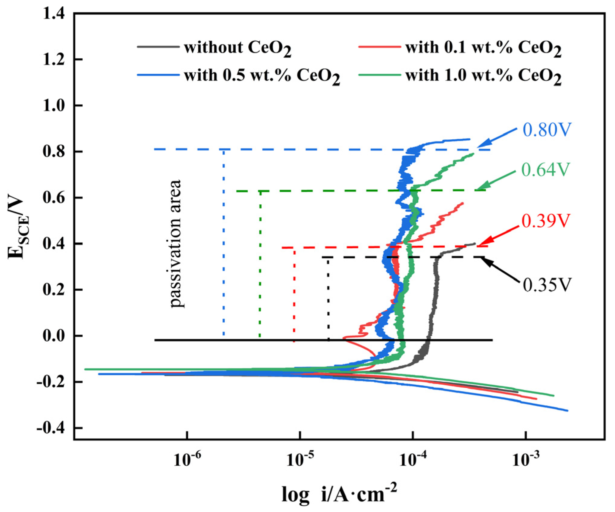
3.4.1. Potentiodynamic Polarization Curve

In general, the corrosion resistance of duplex stainless steel is evaluated by the magnitude of the passivation current and the breakdown potential. The passivation current represents the average current passing through the passivation zone, while the breakdown potential is the potential when the corrosion current undergoes a sudden change through passivation. Figure 6 shows the electrochemical polarization curves of the duplex stainless steel cladding layer under different CeO2 contents. After adding CeO2 into the powders, the polarization curve of the cladding layer shifted to the left and the passivation current density decreased. When the CeO2 content was 0.5 wt.%, the breakdown potential of the cladding layer was the highest, indicating that the optimum addition of CeO2 improved the corrosion resistance of the duplex stainless steel cladding layer.
The polarization curve was fitted by using Cview2 analysis software to obtain the self-corrosion potential and self-corrosion current density, which is listed in Table 5. It can be seen from Table 5 that with the increase in CeO2 content in the powder, the self-corrosion potential increased first and then decreased, which reached a maximum of −0.153V when the CeO2 content was 0.5 wt.%. However, the self-corrosion current density decreased first and then increased, and when the CeO2 content was 0.5 wt.%, it was up to the minimum of 3.18 × 10⁻⁵ A·cm−2. Some research have reported that the higher the self-corrosion potential value and the lower the self-corrosion current density, the slower the corrosion rate of the cladding layer [30]. Therefore, the corrosion resistance of the DSS cladding layer was optimum with a CeO2 content of 0.5 wt.%.
Figure 7 displays the EIS results of the passivation film on the DSS cladding layer with different CeO2 contents. It can be seen from the Nyquist plot in Figure 7a that the capacitance arc shapes of the four passivation films looked the same, but the capacitance arc radius varied greatly. The polarization resistance of the passivation film was related to the radius of the capacitance arc, and an increase in capacitance arc radius means that the passivation film is more stable. When the CeO2 content was 0.5 wt.%, the capacitance arc radius of the passivation film was the largest, which indicated that its passivation film was the most stable and its corrosion resistance was optimal. Figure 7b reflects the relationship between Bode-|Z| and frequency. In general, the higher the |Z| value in the low-frequency range, the better the corrosion resistance of the cladding layer [31]. When the CeO2 content was 0.5 wt.%, the |Z| value was the highest, which meant that the corrosion resistance of the cladding layer reached its optimum. Figure 7c is an equivalent circuit diagram simulating the passivation film corrosion process. In this equivalent circuit diagram, Rs represents the solution resistance and Cdl represents the non-ideal double-layer capacitance of the passivation film. Based on the equivalent circuit diagram, Figure 7a was fitted by using Zview2 software and the data were obtained in Table 6. Rf represents the charge transfer resistance of the passivation film, which can reflect the difficulty of charge crossing the double layer during the corrosion process. The n value in the table is called the dispersion index, which is the dispersion effect caused by the deviation of the passivation film capacitance from the ideal capacitance. The range of n is generally from 0 to 1. The larger the n, the more complete the passivation film [32]. The values of Rf and n reach the maximum with the CeO2 content of 0.5 wt.%, and the corrosion resistance of the DSS cladding layer was optimal.
The active sites on the surface of DSS are the source of its corrosion. These active sites can be divided into two categories, one of which contains sulfides and oxides in the material. After adding CeO2, Ce element reacts with sulfur oxides to form the high-melting-point Ce-oxysulfide, which float out of the steel liquid, and the residual Ce-inclusions have strong corrosion resistance [33,34]. Some scholars also reported that although Ce-inclusions had strong corrosion resistance, once the excessive CeO2 was added, inclusions increased and aggregated to form large particle inclusions, resulting in an increase in the size and quantity of micro-cracks generated between the inclusions and the matrix, thereby reducing the corrosion resistance of the cladding layer [35,36]. Another type of active site is the precipitation phase of DSS, which is rich in Cr and Mo elements. These precipitation phases cause a depletion of Cr and Mo elements around the matrix, reducing the corrosion resistance of these areas.

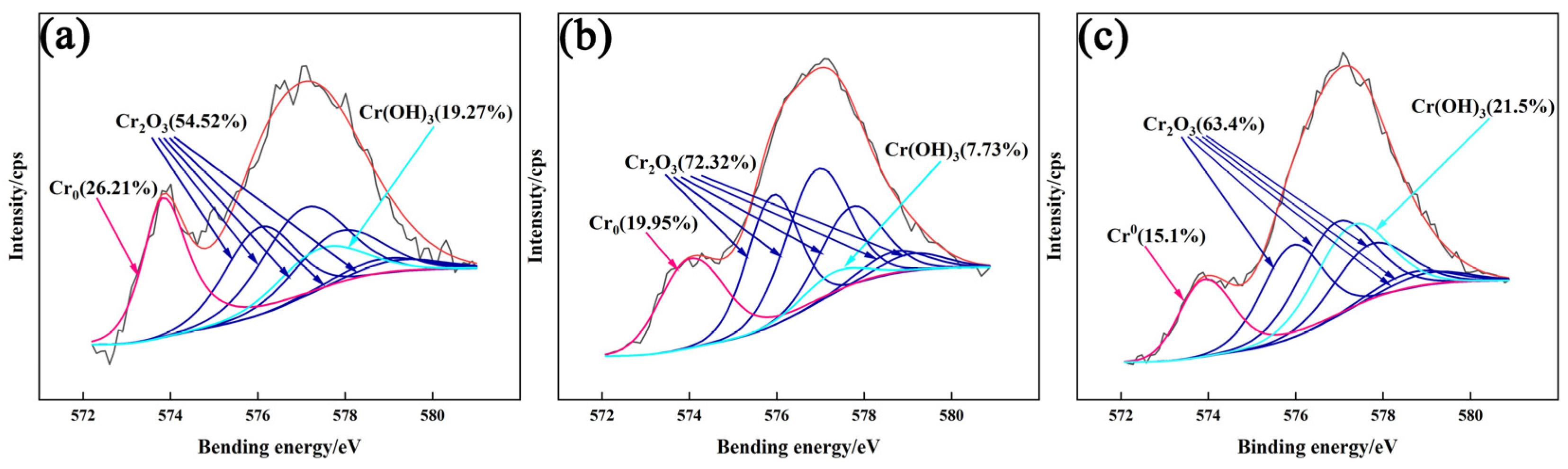
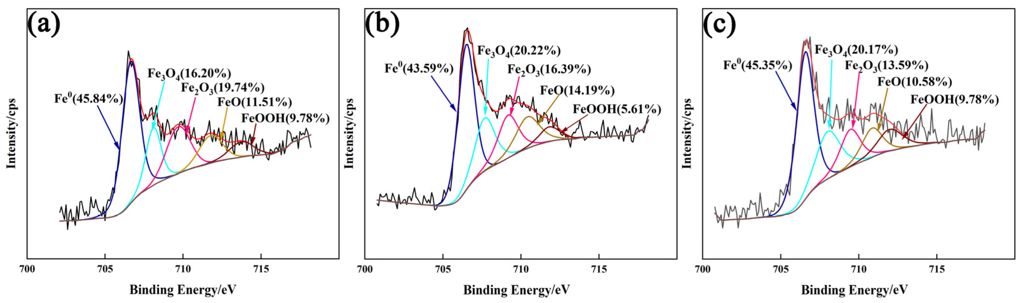
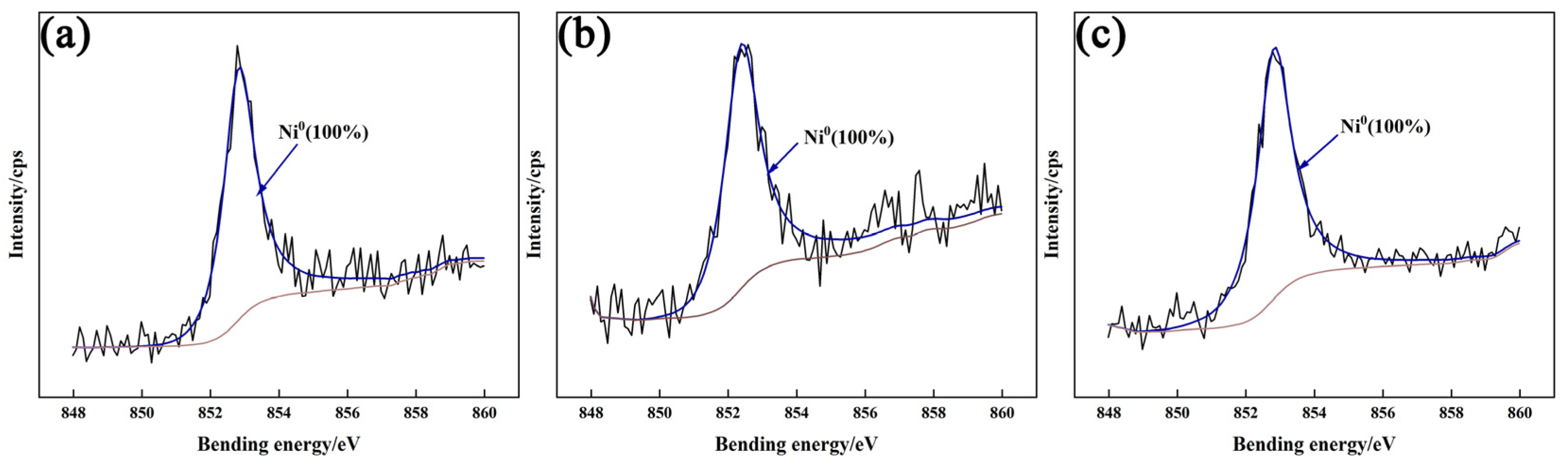
3.4.2. XPS Analysis of Passivation Film

The corrosion resistance of a passivation film is affected by its structure, so it is important to analyze the composition of a passivation film by using XPS testing. Figure 8 shows the XPS total spectra of the passivation film on the surface of the DSS cladding layer under different CeO2 contents. It can be seen from Figure 8 that regardless of whether CeO2 was added, the XPS full spectrum analysis of the passivation film all contained characteristic spectral lines such as Cr2p, Fe2p, Mo3d, Ni2p, and O1s. After adding CeO2 with different contents, the main elements in the passivation film were basically the same, except for slight differences in peak intensity. Among them, the O1s peak was located at 532.08 eV and it had a high peak intensity, which indicated the presence of a large amount of metal oxides in the passivation film.
The peaks corresponding to the four main elements Cr2p, Fe2p, Mo3d, and Ni2p in Figure 8 was performed by high-resolution fine scanning, and the fitting results are shown in Figure 9, Figure 10, Figure 11 and Figure 12, respectively.
From Figure 9, the Cr2P spectrum consisted of three peaks, namely metal Cr0, Cr2O3, and Cr(OH)3. When the CeO2 content was 0.5 wt.%, the content of Cr2O3 was the highest. According to Figure 10, the Fe2p spectrum can be divided into five peaks: metal Fe0, FeO, Fe2O3, Fe3O4, and FeOOH. Fe2+ and Fe3+ mainly existed in the form of iron oxides. From Figure 11, Mo in the passivation film mainly existed in the form of metal Mo0, Mo4+, and Mo6+. From Figure 12, the Ni2p spectrum shows a characteristic peak of metal Ni0. Ni is a stable austenitizing element, which has strong chemical stability.
Research had reported that the passivation film of duplex stainless steel maintained a double-layer structure, which was mainly composed of an outer layer of Fe2O3 and Cr(OH)3, as well as an inner layer of Cr2O3 and FeO [37,38]. In the passivation film, Cr formed a network structure of Cr-O-Cr along a three-dimensional direction, which increased the dissolution resistance of Fe [39,40,41]. The content of Cr2O3 was an important indicator determining the corrosion resistance of stainless steel [42]. Mo can prevent Cl in the solution from being adsorbed onto the surface of the passivation film and reduce the migration rate of Cl. Mo6+ can promote the formation of Cr2O3 [43,44]. The addition of CeO2 changed the element distribution in the cladding layer. Ce element forms aggregation at the grain boundary, which can strengthen the phase boundary and reduce the surface energy of the phase boundary. It inhibited the enrichment of Cr element at grain boundaries to reduce the generation of harmful precipitates in the cladding layer, and it improved the effective solid solution of Cr in the cladding layer, which ultimately promoted the increasing of Cr2O3 [45]. When the CeO2 content was 0.5 wt.%, the proportion of Cr2O3 in the passivation film was the highest, thus exhibiting best corrosion resistance. When the CeO2 content was further increased, Ce-Cr-Fe type intermetallic compounds formed in the cladding layer so that the content of Cr2O3 in the passivation film decreased, thus reducing the corrosion resistance of the cladding layer

4. Conclusions

The 2205 DSS cladding layer was prepared on the surface of Q345 steel by plasma arc cladding technology. The effects of different CeO2 content on the macro-morphology, austenite/ferrite ratio, and corrosion resistance of the cladding layer were studied. The main conclusions were drawn as follows:
(1)
The addition of CeO2 modified the appearance of the 2205 DSS cladding layer and decreased the dilution ratio of the substrate to the cladding layer; when the content of CeO2 was 0.5 wt.%, the appearance of cladding layer was optimal. The content of CeO2 increased from 0 wt.% to 1.0 wt.%, while the dilution rate decreased from 11.2% to 8.3%.
(2)
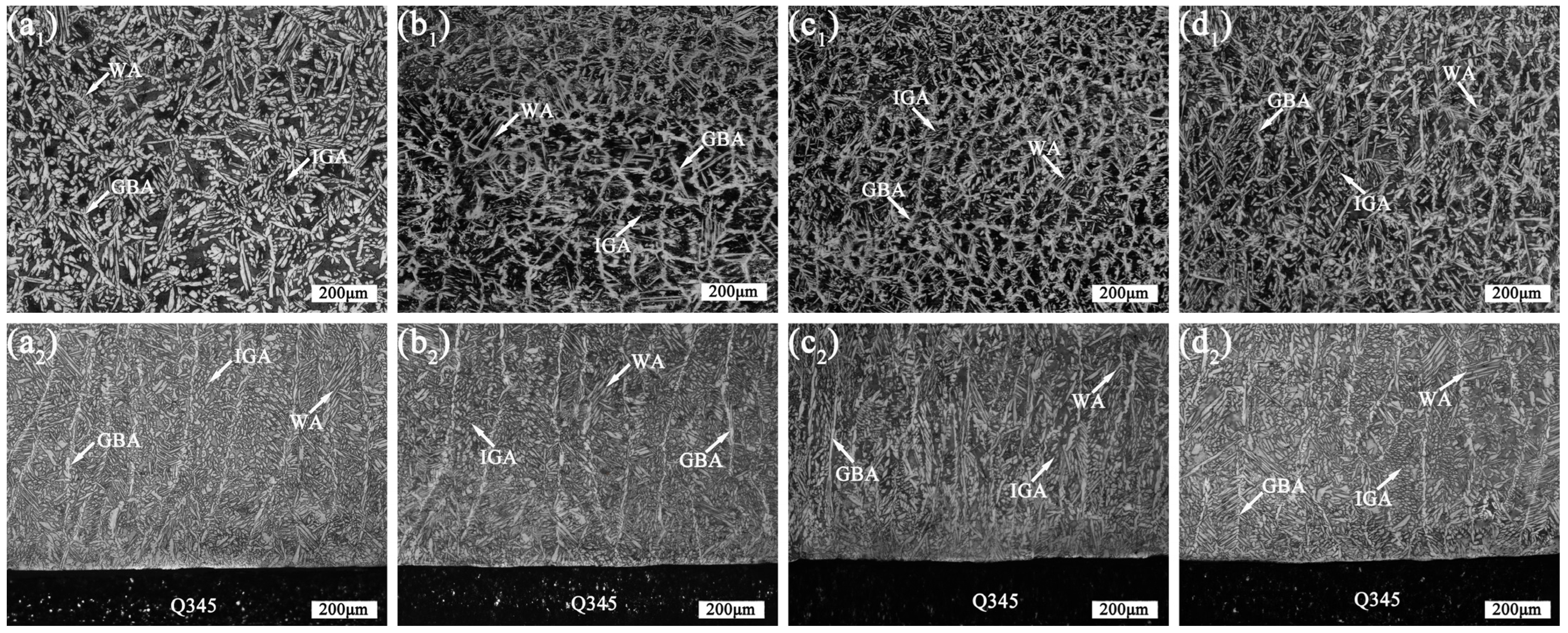
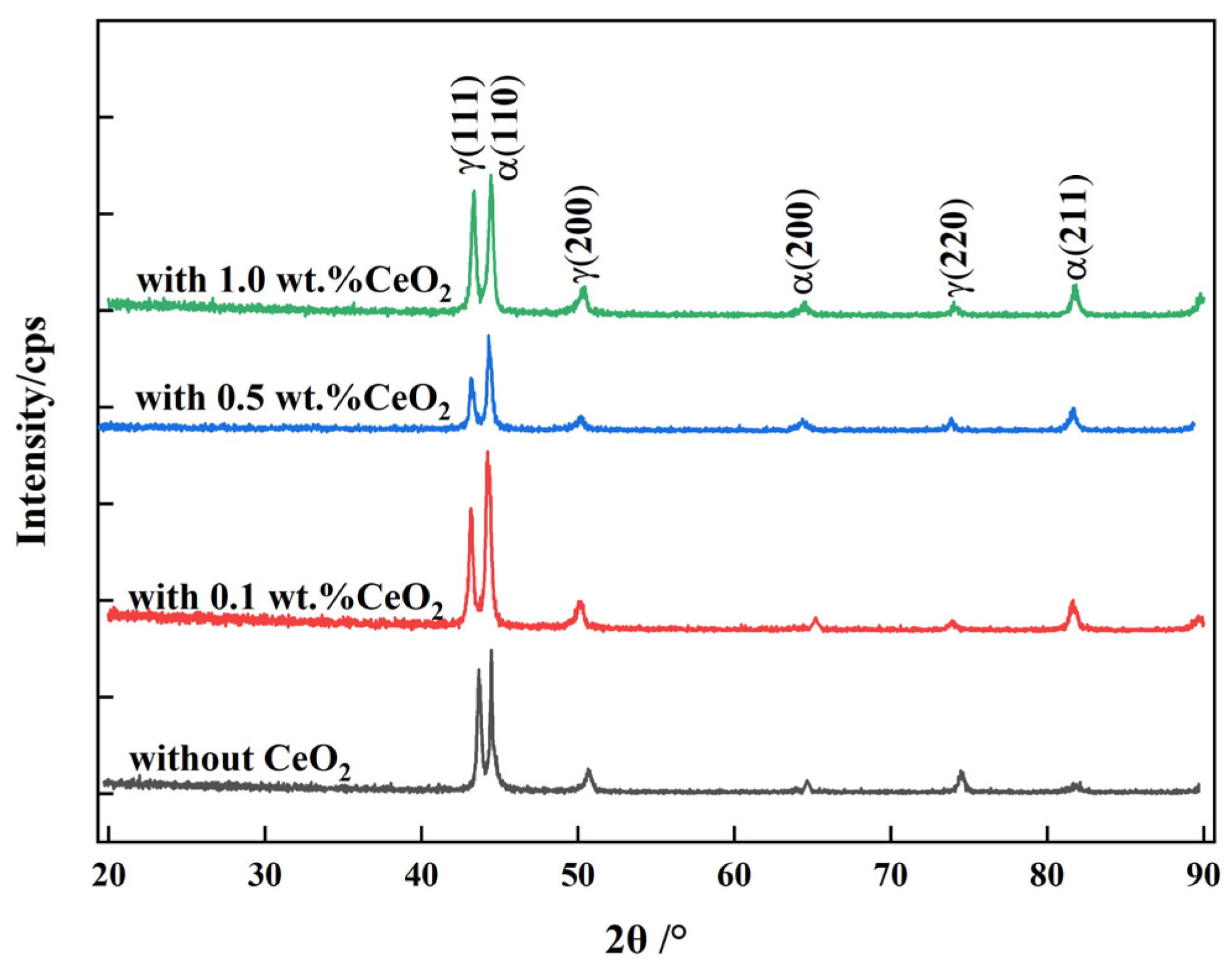
The 2205 DSS cladding layer was composed of the ferrite and the austenite including GBA, IGA, and WA. The addition of CeO2 affected the morphology of the columnar crystal near the matrix, and when the CeO2 content was 0.5 wt.% and 1.0 wt.%, the austenite in the cladding layer was refined and grew in a columnar shape no longer and began to form equiaxed crystals.
(3)
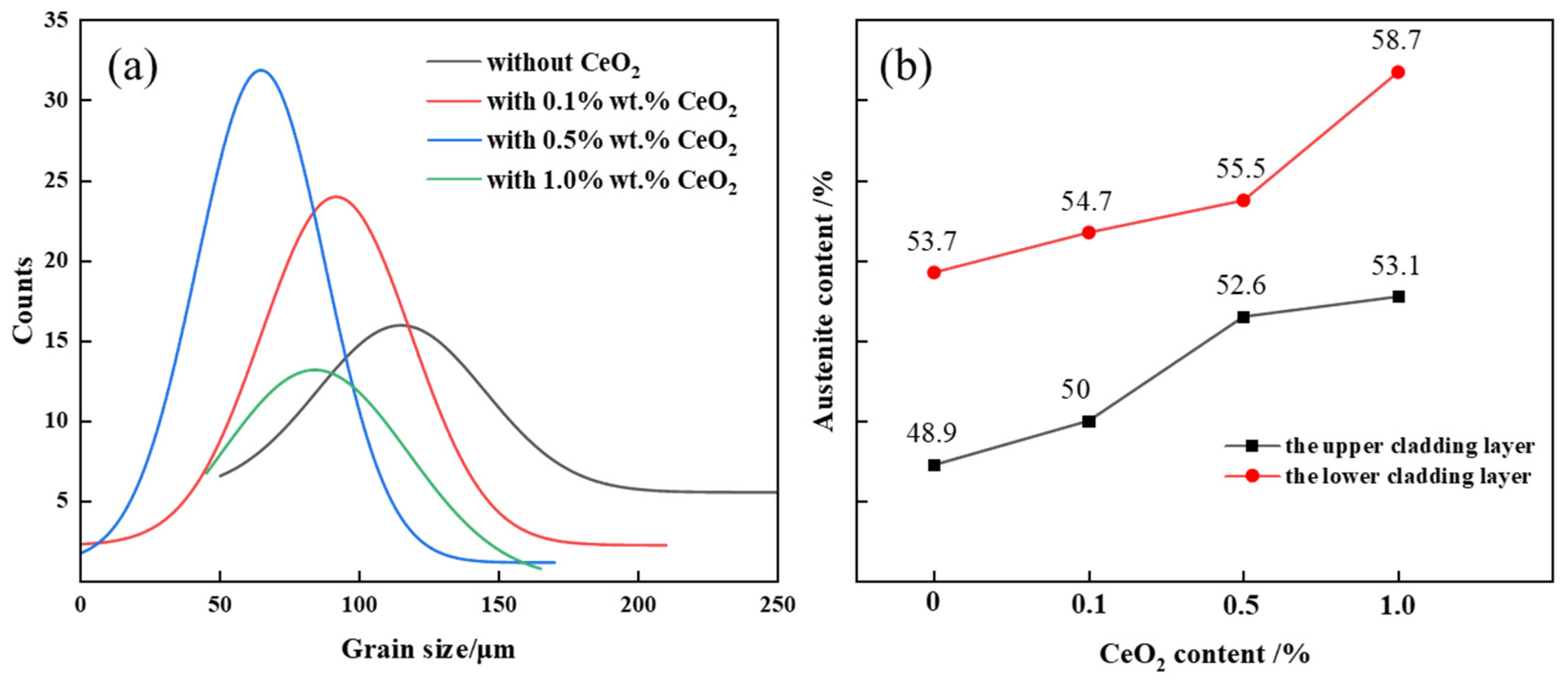
The austenite proportion in the cladding layer increased with the increasing of the CeO2 content. When the CeO2 content was 0.5 wt.%, the austenite proportion in the upper cladding layer and the lower one reached up to 52.6% and 55.5%, respectively. Meanwhile, the austenite proportion in the lower cladding layer was higher than that in the upper one under the action of plasma arc heat cycle.
(4)
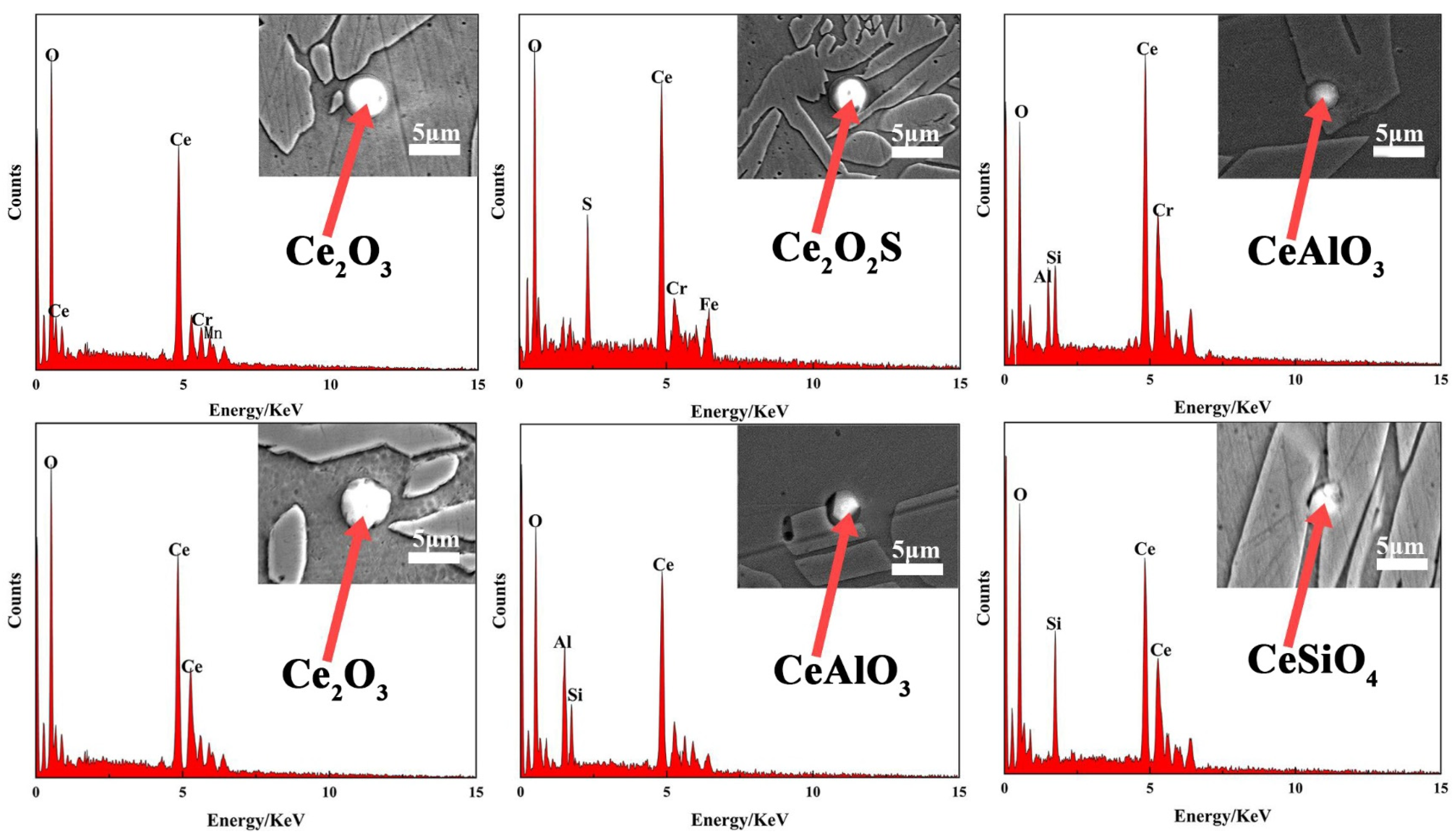
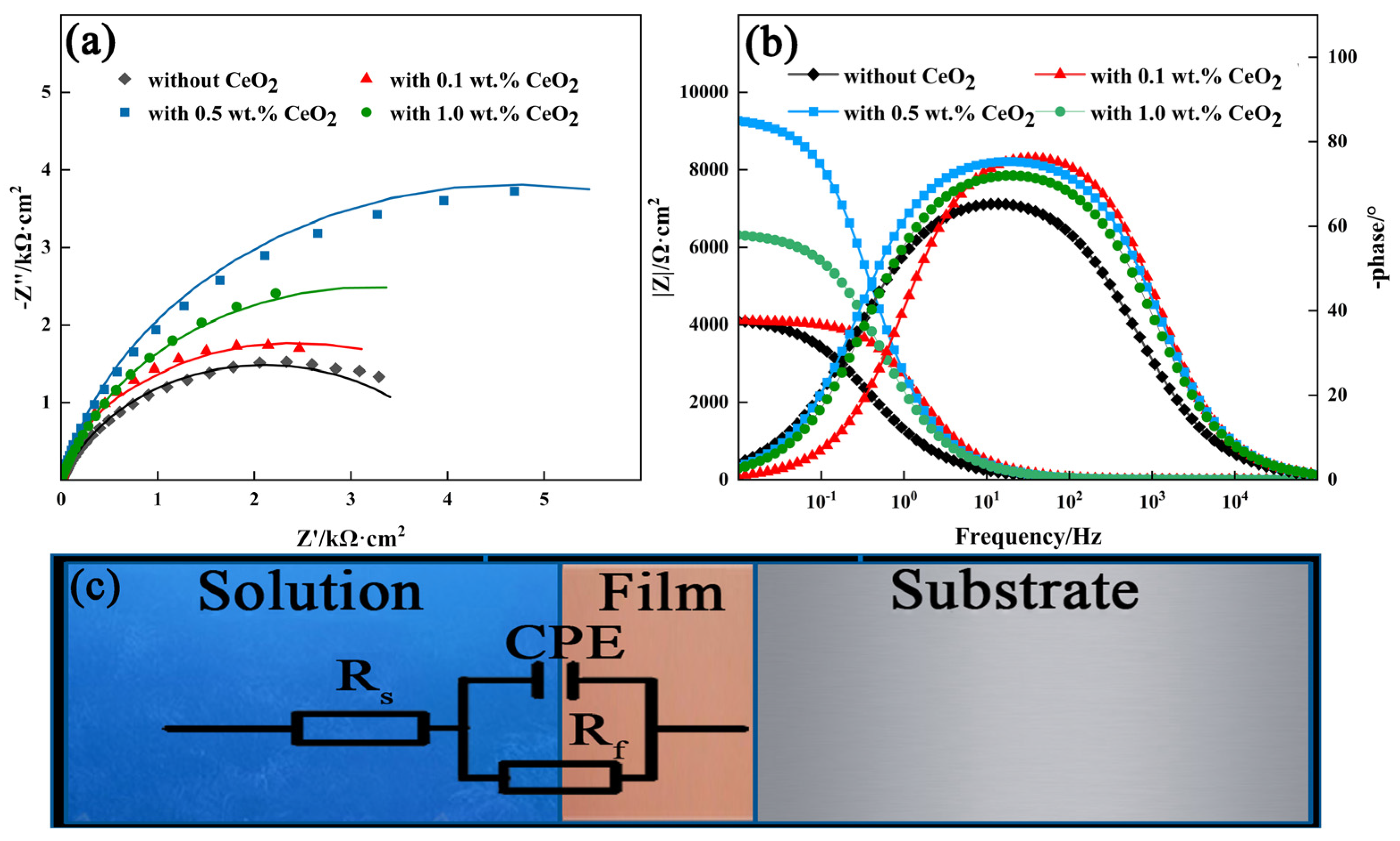
The addition of CeO2 improves the corrosion resistance of the DSS cladding layer, and it was optimum with the CeO2 content of 0.5 wt.%. Ce element promoted the formation of Cr2O3 to improve the corrosion resistance through changing the element distribution of the cladding layer.

Author Contributions

Conceptualization, J.P.; methodology, D.W. and X.S.; validation, F.L. and D.W.; writing—original draft preparation, F.L. and J.P.; writing—review and editing, J.P.; supervision, J.P., X.S. and H.S.; project administration, H.S. and F.L.; funding acquisition, F.L. All authors have read and agreed to the published version of the manuscript.

Funding

This research was supported by The High-level Talent Research Initiation Project of Henan Academy of Science (241820062).

Institutional Review Board Statement

Not applicable.

Informed Consent Statement

Not applicable.

Data Availability Statement

The authors do not have permission to share the data.

Conflicts of Interest

Xiaohui Shi was employed by the company Xinxiang Qixing Brazing Technology Co., Ltd. Huawei Sun was employed by the company Ningbo Intelligent Machine Tool Research Institute Co., Ltd. The remaining authors declare that the research was conducted in the absence of any commercial or financial relationships that could be construed as a potential conflict of interest.

References

  1. Parker, M.E.; Horton, D.J.; Wahl, K.J. Tribocorrosion behavior of 2205 duplex stainless steel in sodium chloride and sodium sulfate environments. Tribol. Lett. 2022, 70, 70. [Google Scholar] [CrossRef]
  2. Yoon, H.; Ha, H.Y.; Kim, S.D.; Lee, T.H.; Jang, J.H.; Moon, J.; Kang, N. Effects of carbon substitution for nitrogen on the pitting corrosion resistance of type UNS S32205 duplex stainless steel. Corros. Sci. 2020, 164, 108308. [Google Scholar] [CrossRef]
  3. Li, G.X.; Du, M.; Wang, J.; Huang, G.S.; Ma, L. Effect of hydrogen on pitting corrosion of 2205 duplex stainless steel under alternating dry/wet marine environment. Int. J. Hydrogen Energy 2023, 48, 17983–17994. [Google Scholar] [CrossRef]
  4. Li, L.; Chen, Q.G.; Fang, Y.; Li, X.P.; Luo, J.H.; Song, C.L.; Wang, S. Failure analysis of 2205 duplex stainless steel connecting pipe for composite plate pressure vessel in a high pressure gas field. Int. J. Press. Vessel. Pip. 2023, 202, 104921. [Google Scholar] [CrossRef]
  5. Varavallo, R.; Moreira, V.D.M.; Paes, V.; Brito, P.; Olivas, J.; Pinto, H.C. Residual stresses of explosion cladded composite plates of ZERON 100 superduplex stainless steel and ASTM SA516-70 carbon steel. Adv. Mater. Res. 2014, 996, 500–505. [Google Scholar] [CrossRef]
  6. Xiao, F.Q.; Wang, D.P.; Hu, W.B.; Cui, L.; Gao, Z.M.; Zhou, L.J. Effect of interlayers on microstructure and properties of 2205/Q235B duplex stainless steel clad plate. Acta Metall. Sin. (Engl. Lett.) 2020, 33, 679–692. [Google Scholar] [CrossRef]
  7. Liu, S.; Fang, W.P.; Yi, Y.Y.; Deng, Y.L. Study on microstructure and properties of flux cored twin-wire CMT welded joint of 2205 duplex stainless steel. Hot Work. Technol. 2020, 49, 16–19+24. [Google Scholar]
  8. Wu, Q.L.; Long, W.M.; Zhang, L.; Zhao, H.W. A review on ceramic coatings prepared by laser cladding technology. Opt. Laser Technol. 2024, 176, 110993. [Google Scholar] [CrossRef]
  9. Liu, E.; Huang, F.F.; Bao, F.H.; Xue, Y.P.; Wang, H.M.; Jin, Y. Microstructure and electrochemical corrosion behaviors of laser-cladded 2205 duplex stainless steel. Steel Res. Int. 2020, 91, 1900456. [Google Scholar] [CrossRef]
  10. Cui, C.; Zhu, X.B.; Cheng, J.Q.; Liu, Z.H.; Han, S.S. Microstructure and Properties of Fe-Based/WC-10Co-4Cr Coatings by Plasma Cladding. Surf. Technol. 2023, 52, 167–176+230. [Google Scholar]
  11. Feng, X.Z.; Zhao, M.; Cao, M.Q. Study on Microstructure and Properties of Fe Based ZrB2-ZrC Compound Coating on Q235 SteeI by PIasma CIadding. Hot Work. Technol. 2019, 48, 106–110+115. [Google Scholar]
  12. Pu, J.; Sun, Y.B.; Wu, L.; He, P.; Long, W.M. Effect of CeO2 Content on Microstructure and Properties of Ni-Based Tungsten Carbide Layer by Plasma Arc Cladding. Coatings 2022, 12, 342. [Google Scholar] [CrossRef]
  13. Hou, P.J.; Mooraj, S.; Champagne, V.K.; Siopis, M.J.; Liaw, P.K.; Gerasimidis, S. Effect of Build Height on Temperature Evolution and Thermally Induced Residual Stresses in Plasma Arc Additively Manufactured Stainless Steel. Metall. Mater. Trans. A 2022, 53, 627–639. [Google Scholar] [CrossRef]
  14. Pu, J.; Xie, P.; Long, W.M.; Wu, M.F.; Sheng, Y.W.; Jie, S. Effect of current on corrosion resistance of duplex stainless steel layer obtained by plasma arc cladding. Crystals 2022, 12, 341. [Google Scholar] [CrossRef]
  15. Gong, W.; Wang, P.F.; Zhang, L.; Jiang, Z.H. Effects of Ce on microstructure and mechanical properties of LDX2101 duplex stainless steel. Metals 2020, 10, 1233. [Google Scholar] [CrossRef]
  16. Shim, S.I.; Park, Y.S.; Kim, S.T.; Song, C.B. Effects of rare earth metal addition on the cavitation erosion-corrosion resistance of super duplex stainless steels. Met. Mater. Int. 2002, 8, 301–307. [Google Scholar] [CrossRef]
  17. Du, T. The effect and mechanism of rare earth elements in metals. Trans. Nonferrous Met. Soc. China 1996, 6, 12–18. [Google Scholar]
  18. Jeon, S.H.; Kim, S.T.; Choi, M.S.; Kim, J.S.; Kim, K.T.; Park, Y.S. Effects of cerium on the compositional variations in and around inclusions and the initiation and propagation of pitting corrosion in hyperduplex stainless steels. Corros. Sci. 2013, 75, 367–375. [Google Scholar] [CrossRef]
  19. Xu, Z.Z.; Wang, Z.Y.; Chen, J.; Qiao, Y.X.; Zhang, J.W.; Huang, Y.M. Effect of rare earth oxides on microstructure and corrosion behavior of laser-cladding coating on 316L stainless steel. Coatings 2019, 9, 636. [Google Scholar] [CrossRef]
  20. Han, S. Effect of Rare Earth Ce on Inclusions in Q345 Steel. Acad. J. Mater. Chem. 2023, 4, 59–62. [Google Scholar]
  21. Li, N.; Lu, Q.Y.; Wang, Y.Q.; Zhu, Z.H.; Xiang, L.; Qiu, S.T. Effect of Ce on inclusions modification in 2.9%Si–0.8%Al non-oriented electrical steel. J. Iron Steel Res. 2017, 29, 570–576. [Google Scholar]
  22. Hemmati, I.; Ocelik, V.; De-Hosson, J.T.M. Dilution effects in laser cladding of Ni-Cr-B-Si-C hardfacing alloys. Mater. Lett. 2012, 84, 69–72. [Google Scholar] [CrossRef]
  23. Shu, D.; Dai, S.C.; Wang, G.; Si, W.D.; Xiao, P.; Cui, X.X.; Chen, X. Influence of CeO2 content on WC morphology and mechanical properties of WC/Ni matrix composites coating prepared by laser in-situ synthesis method. J. Mater. Res. Technol. 2020, 9, 11111–11120. [Google Scholar] [CrossRef]
  24. Yang, C.; Jiang, C.N.; Fu, T.L.; Lin, T.; Guo, W.M.; Liu, N.N. Effect of CeO2 on the microstructure and properties of AlCoCrFeNi2.1 laser cladding coatings. J. Alloys Compd. 2024, 976, 172948. [Google Scholar] [CrossRef]
  25. Zhang, S.H.; Yu, Y.C.; Wang, S.B.; Li, H. Effects of cerium addition on solidification structure and mechanical properties of 434 ferritic stainless steel. J. Rare Earths 2017, 35, 518–524. [Google Scholar] [CrossRef]
  26. Ma, Q.Q.; Wu, C.C.; Cheng, G.G.; Li, F.W. Characteristic and formation mechanism of inclusions in 2205 duplex stainless steel containing rare earth elements. Mater. Today Proc. 2015, 2, S300–S305. [Google Scholar] [CrossRef]
  27. Wang, H.; Wang, A.Q.; Li, C.Y.; Yu, X.S.; Xie, J.P.; Liang, T.T.; Liu, C.L. Effects of rare earth metals on microstructure, mechanical properties, and pitting corrosion of 27% Cr hyper duplex stainless steel. Rev. Adv. Mater. Sci. 2022, 61, 873–887. [Google Scholar] [CrossRef]
  28. Xu, Z.M.; Liang, G.F.; Guan, Q.F.; Jiang, Q.H. TiC as heterogeneous nuclei of the (Fe, Mn)3C and austenite intergrowth eutectic in austenite steel matrix wear resistant composite. Mater. Res. Bull. 2004, 39, 457–463. [Google Scholar]
  29. Huang, J.F.; Fang, H.S.; Yu, G.C.; Zheng, Y.K. Study of Re-Ti Multi-modification on Grain Refinement of Bainitic Cast Steel. Heat Treat. Met. 1999, 9, 5–9. [Google Scholar]
  30. Zang, Q.Y.; Jin, Y.F.; Zhang, T.; Yang, Y.T. Effect of yttrium addition on microstructure, mechanical and corrosion properties of 20Cr13 martensitic stainless steel. J. Iron Steel Res. Int. 2020, 27, 451–460. [Google Scholar] [CrossRef]
  31. Ma, K.; Liu, D.T.; Cheng, Y.H.; Wan, Y.X.; Ren, H.W.; Jeyaprakash, N.; Wang, H.N.; Yang, J.Y. Investigation of corrosion resistance offered by the Fe-based clad layer under salt spray and electrochemical workstations. Surf. Coat. Technol. 2024, 494, 131482. [Google Scholar] [CrossRef]
  32. Ma, M.Y.; He, C.L.; Chen, L.Q.; Wei, L.L.; Misra, R.D.K. Effect of W and Ce additions on the electrochemical corrosion behaviour of 444-type ferritic stainless steel. Corros. Eng. Sci. Technol. 2018, 53, 199–205. [Google Scholar] [CrossRef]
  33. Gao, J.B.; Chang, P.F.; Zhang, B.B.; Jiang, Z.H.; Li, H.B. Effect of Ce on inclusion modification in a new type super duplex stainless steel 2707HD. Iron Steel 2018, 53, 37–44. [Google Scholar]
  34. Liu, X.; Wang, L.M. Effects of rare earth addition on the inclusions and mechanical properties of 2205 duplex stainless steel. Adv. Mater. Res. 2012, 503, 463–468. [Google Scholar] [CrossRef]
  35. Zhang, J.; Sun, Y.; Zhang, S.K.; Zhang, L.F. Effect of rare earth element yttrium modified inclusion on corrosion properties of stainless steel. Mater. Today Commun. 2024, 39, 109185. [Google Scholar] [CrossRef]
  36. Lee, T.K.; Kim, H.J.; Kang, B.Y.; Hwang, S.K. Effect of inclusion size on the nucleation of acicular ferrite in welds. ISIJ Int. 2000, 40, 1260–1268. [Google Scholar] [CrossRef]
  37. Liu, X.; Ju, D.C.; Chen, L. Effect of rare earth metals on passivation behavior of UNS S31803 duplex stainless steel in sulfuric acid solution. Constr. Build. Mater. 2024, 421, 135644. [Google Scholar] [CrossRef]
  38. Ming, J.; Zhou, X.C.; Shi, J.J. Feasibility of using 2304 duplex stainless steel in seawater-mixed concrete pore solutions: A preliminary passivation consideration. Constr. Build. Mater. 2024, 438, 137037. [Google Scholar] [CrossRef]
  39. Souto, R.M.; Rosca, I.C.M.; González, S. Resistance to localized corrosion of passive films on a duplex stainless. Corrosion 2001, 57, 300–306. [Google Scholar] [CrossRef]
  40. Fujimoto, S.; Newman, R.C.; Smith, G.S.; Kaye, S.P.; Kheyrandish, H.; Colligon, J.S. Passivation thresholds in iron-chromium alloys prepared by ion-beam sputtering. Corros. Sci. 1993, 35, 51–55. [Google Scholar] [CrossRef]
  41. Williams, D.E.; Newman, R.C.; Song, Q.; Kelly, R.G. Passivity breakdown and pitting corrosion of binary alloys. Nature 1991, 350, 216–219. [Google Scholar] [CrossRef]
  42. Zhang, B.; Wei, X.X.; Wu, B.; Wang, J.; Shao, X.H.; Yang, L.X.; Zheng, S.J.; Zhou, Y.T.; Jin, Q.Q.; Oguzie, E.E.; et al. Chloride attack on the passive film of duplex alloy. Corros. Sci. 2019, 154, 123–128. [Google Scholar] [CrossRef]
  43. Zhang, H.Q.; Peng, K.; Chen, X.Z. Duplex stainless steel 2209 with excellent properties deposited by plasma arc additive manufacturing without post heat-treatment: Favorable phase ratio and no σ-phase. Arch. Civ. Mech. Eng. 2024, 24, 175. [Google Scholar] [CrossRef]
  44. Han, Y.X.; Chi, R.T.; Chen, Q.C.; Wang, B.; Liu, W.; He, Y.L. Microstructural evolution and coarsening behavior of the precipitates in 2205 duplex stainless steel aged at 850 °C. J. Mater. Res. Technol. 2023, 26, 2560–2574. [Google Scholar] [CrossRef]
  45. Liu, X.; Ma, L.F.; Li, Y.G. Effect of La and Ce on corrosion resistance of duplex stainless steel. Trans. Mater. Heat Treat. 2016, 37, 112–118. [Google Scholar]
Figure 1. Appearance and dilution rate of cladding layers with different CeO2 content: (a1,a2) without CeO2; (b1,b2) with 0.1 wt.% CeO2; (c1,c2) with 0.5 wt.% CeO2; (d1,d2) with 1.0 wt.% CeO2; (e) dilution rate variation curve.
Coatings 15 00590 g001
Figure 2. Microstructure of the DSS cladding layer under different CeO2 contents: (a1,a2) without CeO2; (b1,b2) with 0.1 wt.% CeO2; (c1,c2) with 0.5 wt.% CeO2; (d1,d2) with 1.0 wt.% CeO2.
Coatings 15 00590 g002
Figure 3. The austenite characteristics of duplex stainless steel cladding layer under different CeO2 contents: (a) Grain size distribution of austenite in the cladding layer; (b) austenite proportion in the cladding layer.
Coatings 15 00590 g003
Figure 4. XRD phase analysis results.
Coatings 15 00590 g004
Figure 5. The point scanning results of inclusions in the cladding layer with different CeO2 contents.
Coatings 15 00590 g005
Figure 6. Polarization curves of the DSS cladding layer under different CeO2 contents.
Coatings 15 00590 g006
Figure 7. Electrochemical Spectroscopy Impedance (ESI) spectra of the DSS cladding layer under different CeO2 contents: (a) Nyquist diagram; (b) mode-frequency Bode diagram; (c) equivalent circuit diagram.
Coatings 15 00590 g007
Figure 8. XPS total spectrum on the passivation film of duplex stainless steel cladding layer under different CeO2 contents.
Coatings 15 00590 g008
Figure 9. The Cr2p orbit fitting results of the cladding layer: (a) without CeO2; (b) 0.5 wt.% CeO2; (c) 1.0 wt.% CeO2.
Coatings 15 00590 g009
Figure 10. The Fe2p orbit fitting results of the cladding layer: (a) without CeO2; (b) 0.5 wt.% CeO2; (c) 1.0 wt.% CeO2.
Coatings 15 00590 g010
Figure 11. The Mo3d orbit fitting results of the cladding layer: (a) without CeO2; (b) 0.5 wt.% CeO2; (c) 1.0 wt.% CeO2.
Coatings 15 00590 g011
Figure 12. The Ni2p orbit fitting results of the cladding layer: (a) without CeO2; (b) 0.5 wt.% CeO2; (c) 1.0 wt.% CeO2.
Coatings 15 00590 g012
Table 1. The chemical composition of materials (wt.%).
CrNiMoMnSiCCuVAlNPSFeCeO2
220522.55.93.21.50.80.020.030.010.0040.20.020.015Bal00.10.51.0
Q345≤0.3≤0.5≤0.1≤1.7≤0.5≤0.2 ≤0.03≤0.03Bal
Table 2. The choice of cladding process parameters.
Welding CurrentCladding SpeedPowder Feeding SpeedIonic Gas FlowShielding Gas FlowSending Powder FlowHeight of Nozzle
90 A5 mm/s25 cm3/min1.5 L/min15 L/min4 L/min8 mm
Table 3. Possible chemical reactions of cerium during cladding with CeO2 [26,27].
ReactionΔG/J·mol−1 (1873k)
CeO2 Content
0.1 wt.%0.5 wt.%1.0 wt.%
[Ce] + 2[O] = CeO2−59,328−90,472−137,189
[Ce] + 3/2[O] = 1/2Ce2O3−81,930−128,647−144,219
[Ce] + [O] + 1/2[S] = 1/2Ce2O2S−69,767−100,064−137,228
[Ce] + [Al] + 3[O] = CeAlO3−185,818−232,534−279,250
[Al] + 3/2[O] = 1/2Al2O3−37,850−39,251−46,882
Table 4. The mismatch δ between the basal phase and nucleation phase.
CASE[hkl]s[hkl]nd [uvw]s/nmd [uvw]n/nmθ/°δ
[ 1 2 ¯ 1 ¯ 0 ][ 1 ¯ 10 ]0.38890.414570
Ce2O3(0001)//δ-Fe(111)[ 1 ¯ 100 ][ 2 ¯ 11 ]0.67360.7180606.19%
[ 2 ¯ 110 ][ 1 ¯ 01 ]0.38890.414570
[1 2 ¯ 1 ¯ 0 ][ 1 ¯ 10 ]0.40.414570
Ce2O2S(0001)//δ-Fe(111)[ 1 ¯ 100 ][ 2 ¯ 11 ]0.69290.7180603.52%
[ 2 ¯ 110 ][ 1 ¯ 01 ]0.40.414570
Table 5. Potentiodynamic polarization curve fitting results.
CeO2/wt.%Self-Corrosion Potential/VSelf-Corrosion Current Density/A·cm−2
0−0.1787.79 × 10−5
0.1−0.1654.22 × 10−5
0.5−0.1533.18 × 10−5
1.0−0.1735.42 × 10−5
Table 6. Equivalent circuit fitting results.
DSSRs (Ω·cm−2)Cdl (F·cm−2)Rf (Ω·cm−2)n
Without CeO29.551.57 × 10−442080.81
0.1 wt.% CeO26.754.71 × 10−541000.89
0.5 wt.% CeO26.416.62 × 10−593790.96
1.0 wt.% CeO27.567.91 × 10−563940.90
Disclaimer/Publisher’s Note: The statements, opinions and data contained in all publications are solely those of the individual author(s) and contributor(s) and not of MDPI and/or the editor(s). MDPI and/or the editor(s) disclaim responsibility for any injury to people or property resulting from any ideas, methods, instructions or products referred to in the content.

