Article

Interfacial Modulation of Laser-Deposited Ti6Al4V-TiC Wear-Resistant Coatings: Surface Ni-P Metallization of TiC Particles

1
Institute of Advance Wear & Corrosion Resistant and Functional Materials, National Joint Engineering Research Center of High Performance Metal Wear Resistant Materials Technology, Jinan University, Guangzhou 510632, China
2
College of Mechatronics Engineering and Automation, Foshan University, Foshan 528225, China
3
Ruyuan Dongyangguang UACJ Fine Foil Co., Ltd., Shaoguan 512721, China
4
GD Midea Air-Conditioning Equipment Co., Ltd., Foshan 528311, China
*
Authors to whom correspondence should be addressed.
Coatings 2025, 15(6), 629; https://doi.org/10.3390/coatings15060629
Submission received: 21 April 2025 / Revised: 20 May 2025 / Accepted: 21 May 2025 / Published: 24 May 2025
(This article belongs to the Special Issue Laser Surface Engineering and Additive Manufacturing)

Abstract

:
Prior to the laser processing, the surface of the TiC-reinforced particles underwent a metallization process with Ni-P, with the objective of enhancing the wettability between the TiC and the Ti6Al4V, thereby ensuring enhanced wear resistance of the titanium-based composite (TMC) coatings. In this study, the chemical deposition method was utilized to synthesize three types of metallized TiC with varying phosphorus contents. The P contents of these samples were determined to be 9.12 wt.% (HP metallized TiC), 6.55 wt.% (MP metallized TiC), and 1.71 wt.% (LP metallized TiC). It was observed that the thickness of the coatings increased in a gradual manner with the decrease in P. Furthermore, the coating of the LP metallized TiC was found to possess the highest degree of crystallinity and a microcrystalline structure. The 50 wt.% TiC-Ti6Al4V composite coatings (TMC-Nickel-free, TMC-HP, TMC-MP, and TMC-LP) were produced by laser fusion deposition using untreated TiC and three metallized TiC enhancements. The findings indicate that TMC-LP exhibits cracking only during the initial processing stage. Surface metallization has been shown to enhance the wear resistance of composite coatings through several mechanisms, including increased bonding of the ceramic phase to the metal matrix and the formation of hard Ti2Ni compounds. The wear rates of TMC-HP, TMC-MP, and TMC-LP were reduced by 22%, 43%, and 72%, respectively, in comparison to TMC-Nickel-free.

Graphical Abstract

1. Introduction

Titanium alloys are extensively utilized in aerospace applications due to their low density and high specific strength. However, their operational lifespan is considerably limited by the low plastic shear resistance, restricted work-hardening abilities, and insufficient protective efficacy of the brittle oxide coating [1]. Laser melting deposition (LMD) of ceramic-reinforced titanium matrix composite (TMC) coatings has been shown to significantly enhance the wear resistance of titanium alloys, leveraging the advantages of the reinforcing ceramic phase [2]. Nevertheless, TMCs coatings are highly susceptible to cracking caused by the significant differences in the coefficient of thermal expansion, melting point, and wettability between the metallic and ceramic phases. As the ceramic addition increases, the likelihood of incomplete fusion and residual stresses within the coating rises, leading to weaker adhesion at the interface [3]. When exposed to mechanical stress, the interfacial bond between the ceramic matrix and the metal substrate becomes compromised, leading to the detachment of ceramic particles and the onset of abrasive wear. This process significantly exacerbates the extent of the damage [4].
The employment of composite coatings characterized by elevated ceramic concentrations is a compelling proposition, primarily due to their remarkable degree of hardness. However, these coatings are susceptible to peeling and cracking issues arising from inadequate fusion. In the domain of ceramic-reinforced metal matrix composites, meticulous analysis is imperative in the design process. This analysis encompasses the compatibility of thermophysical properties, interface structure, and characteristics between the metal and ceramic components. These factors are essential for developing robust bonding coatings. TiC ceramic particles are considered a promising reinforcement for titanium matrix composites because of their high chemical stability, exceptional hardness, and comparable coefficients of thermal expansion and density to the titanium matrix. These properties contribute to the enhanced tribological performance of the composites [5,6,7]. Laser melting deposition is a high-temperature, non-stationary process, the efficacy of which is contingent upon the effective wetting of the ceramic by the metal. It is imperative to resolve the conflict between achieving optimal bonding and incorporating elevated ceramic content in order to enhance the wear resistance of metal–ceramic composite coatings. Among these considerations, wettability remains the primary concern [8].
In order to enhance the wettability of ceramics with metals, a variety of methods are frequently utilized, including reactive elements, field-assisted techniques, and surface metallization are frequently utilized. Chemical deposition is a widely adopted surface metallization technique for ceramics due to its economic production cost and precise control of the deposition process [9,10]. Nickel (Ni) [11], cobalt (Co) [12], and copper (Cu) plating [13] are commonly used chemical deposition techniques because of their reducibility and stability. The chemical deposition of nickel on ceramic surfaces has been shown to be a particularly effective method of improving interfacial interactions in metal–ceramic composites and enhancing the wettability of ceramic surfaces [14,15]. By reinforcing with TiC ceramic particles, the wetting angle between Ni and TiC ceramics is small, resulting in strong bonding [16]. Additionally, the potentially formed Ti2Ni phase may further enhance adhesion between nickel and titanium [17]. Consequently, the deposition of nickel on the surface of TiC particles can enhance the bonding efficacy between the ceramic and the metal to a significant degree. Borohydrides, hydrazine compounds, and hypophosphates are frequently utilized as reducing agents in the chemical reduction and deposition of nickel [18]. In view of the high toxicity of borohydride and hydrazine compounds, hypophosphates have become the preferred choice with regard to safety and environmental sustainability [19]. During the Ni plating process, employing hypophosphates as a reducing agent results in the introduction of phosphorus (P) into the nickel layer. However, it is important to note that the melting point and crystallinity of the coating are significantly influenced by the phosphorus content [20]. As demonstrated by Y.M. Chow et al. [21], electroless nickel plating with a low phosphorus content exhibited a wetting force that was three times greater than that of high-phosphorus electroless nickel plating when tested in a welding context. J. Xiao et al. [22] reported that Ni-3.5%P plating with higher crystallinity yielded optimal weldability and shear resistance when compared to Ni-P plating with lower crystallinity. Furthermore, research by Mao Wu et al. [23] compared the welding performance of nickel–phosphorus coatings and solders, revealing that nickel (4 wt.%) solder joints demonstrated greater reliability than those with nickel (10 wt.%).
As previously stated, the phosphorus content of a coating exerts a substantial influence on weldability, which in turn affects the mechanical properties of the welded joint. Weldability can be defined as the ability to join metals without the formation of cracks or detrimental defects, thereby ensuring optimal mechanical quality and a robust bond between dissimilar materials. This characteristic is of particular importance for TMC coatings manufactured through LMD given that the process involves a high-temperature, non-stable, semi-molten environment. Nickel–phosphorus (Ni-P) coatings can be classified into three categories based on the phosphorus content: low phosphorus (1 wt.% to 4 wt.%), medium phosphorus (5 wt.% to 8 wt.%), and high phosphorus (9 wt.% to 12 wt.%) [24]. The effect of Ni-P metallization with different P contents on interfacial improvement during LMD has not yet been fully explored.
In order to obtain wear-resistant TMC coatings with high ceramic content, Ni-P metallization was performed on the surface of TiC-reinforced particles prior to LMD. This process was undertaken to improve the wettability between the ceramic and the metal, taking into account the thermophysical differences between the metal and the ceramic. This study investigated the effect of Ni-P metallization with different P contents on the preparation and mechanical properties of laser melting deposited TMC. The rationale for this investigation was that P content affects the weldability of the metallized shell layer. The study was validated by a statistical design of experiments, and its objective was to determine the optimal window of optimal P content among the three kinds of Ni-P metallization to balance crack inhibition and wear resistance.

2. Experiment

2.1. Chemical Deposition Process

In this study, mechanically crushed TiC particles (99.9 wt.%, Suzhou Sub-Nano New Material Technology Co., Ltd., Suzhou, China,) were selected as the base material for ceramic surface metallization, with a particle size of 40–100 μm. Metallized TiC ceramic powders were prepared by chemical deposition, a process which differs from the previous three-step treatment (roughening, sensitization, and activation). In view of the fact that the surface of the ceramic particles was found to be both rough and resistant to corrosion, it was determined that a mere two steps, namely sensitization and activation, would suffice in the treatment of the ceramic particles prior to chemical deposition. The chemical deposition process comprised a series of consecutive steps: (1) The sensitization treatment was conducted using a SnCl2 hydrochloric acid solution at 25 °C for a duration of 15 min, followed by rinsing with deionized water. (2) The activation treatment was conducted using a PdCl2 hydrochloric acid solution at 25 °C for a duration of 15 min, followed by rinsing with deionized water. (3) The P content in the Ni-P plating was controlled by adjusting the concentration of phosphorus-reducing salt and additive in the plating solution (see Table 1 for details of the deposition conditions). In this experiment, a dual complexing agent system was utilized that possesses optimal buffering capacity [25]. Separate plating tanks were utilized to prepare Ni-P plating with low-, middle-, and high-phosphorus contents on pretreated TiC ceramic particles. The plating solution loading, defined as the ratio of the original mass of TiC particles to the plating solution volume, was set to 15 g/L. In order to obtain a fine and uniform plating and to reduce particle agglomeration, the TiC particles were evenly dispersed in the bath using a stirrer and stirred at 180 rpm with a homemade stirring bar. Finally, the powders were washed repeatedly in deionized water, filtered, and dried in an oven at 80 °C for 24 h. For the sake of clarity and concision, the high-phosphorus content is denoted by HP, the medium-phosphorus content by MP, and the low-phosphorus content by LP.

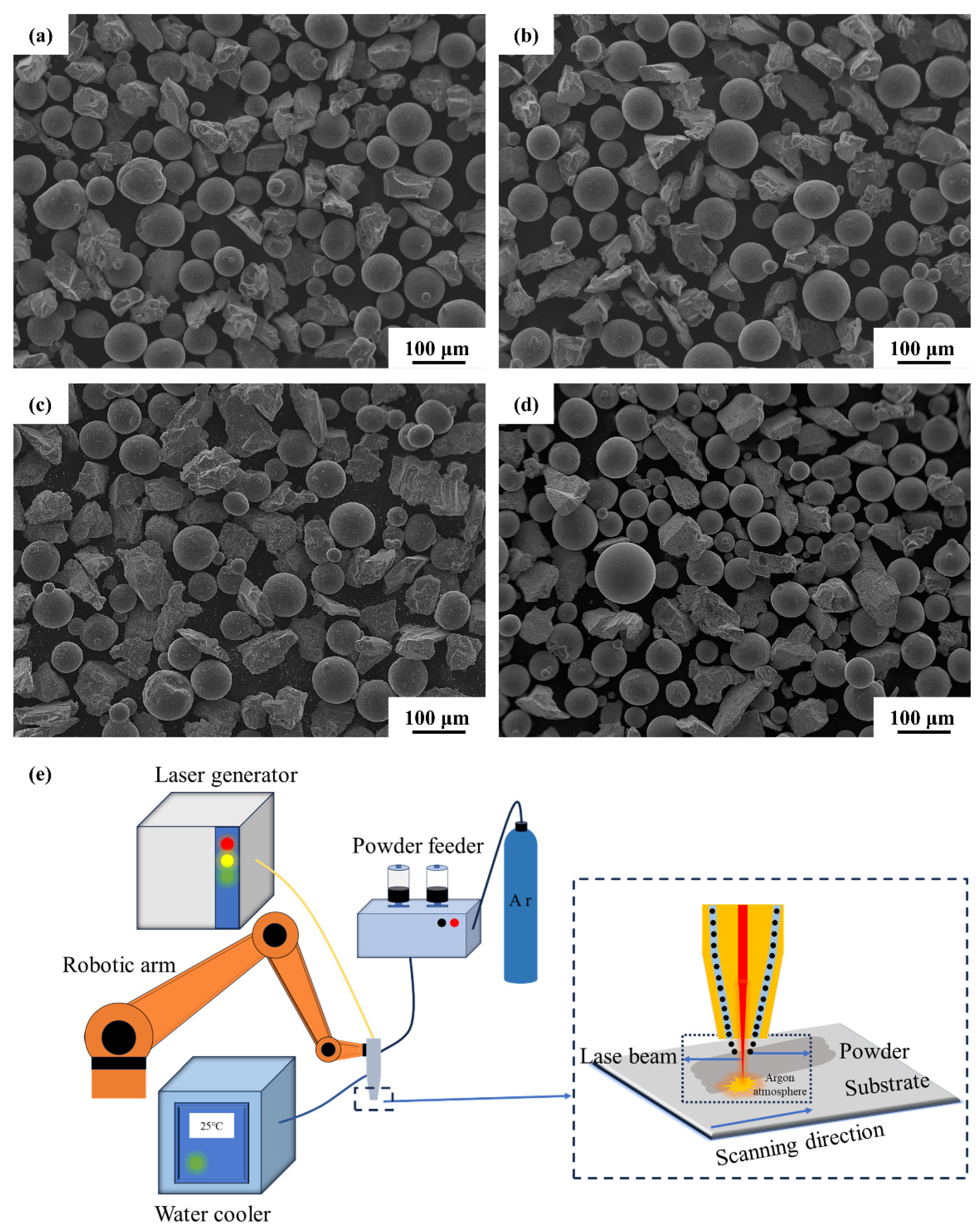
2.2. Laser Melting Deposition Process

The substrate used in this study was a Ti6Al4V annealed plate with dimensions of 140 mm × 140 mm × 10 mm (Dongguan Guanyue Metal Materials Co., Ltd., Dongguan, China). The substrate underwent a process of abrading with silicon carbide sandpaper of grit size 600, a procedure intended to remove surface oxides and impurities; it was then subjected to a cleaning with alcohol. Gas-atomized Ti6Al4V spherical powder was utilized as the raw material for the metal powder, with a particle size ranging from 45 to 105 μm (Qinghe Chuangjia Welding Material Co., Ltd., Xingtai, China). The chemical composition of the metal powders is shown in Table 2. Ti6Al4V powder has been shown to exhibit high sphericity, rendering it well suited for laser melting deposition. In contrast, the irregular shape and poor fluidity of TiC powder limit its applicability. Metallized TiC powder (50 wt.%) was mixed with the metal powder for 4 h through mechanical rotation in order to prepare the metal–ceramic composite powder (Figure 1a–d). HP, MP, and LP metallized TiC-Ti6Al4V composite coatings were prepared using an AC-6000-R/01 automated ultra-high-speed laser additive system (Figure 1e). The laser processing parameters are outlined below: laser power of 2.0 kW, laser spot diameter of 3 mm, scanning speed of 10 mm/s, and powder-feeding speed of 2 r/min.

2.3. Microstructural Characterization and Mechanical Properties

The surface and cross-sectional chemical composition distributions of HP, MP, and LP metallized TiC powder were analyzed using a field emission scanning electron microscope (FE-SEM, Phenom XL, Eindhoven, The Netherlands) equipped with an energy dispersive spectrometer. The surface of the metallized ceramic particles was observed using the secondary electron mode of the scanning electron microscope (EM-30+, Coxem, Daejeon, Republic of Korea). The metallized ceramic powder was embedded in the resin and subsequently polished to 4000 mesh. The cross-section was observed in the backscattering mode in order to characterize the thickness. The phase structure of the metallized TiC powder surface was analyzed by using X-ray diffraction (XRD, Rigaku Ultima IV, Tokyo, Japan) with Cu Kα rays (λ = 1.54178 Å). The X-ray intensity employed was 40 kV, the current was 40 mA, and the scanning speed was 2°/min.
The specimen was processed perpendicular to the laser scanning direction into a block measuring 10 mm × 20 mm × 10 mm. The sample was ground, polished, and then etched using Kroll reagent. The phase and microstructure of the functional composite coating were analyzed using X-ray diffraction (XRD) and scanning electron microscopy (SEM). The microhardness of the cross-section of the composite coating was evaluated by means of a Vickers microhardness tester (HXD-1000TM) with a load of 500 gf and a continuous load of 15 s. Each hardness value is the average of three measurements to ensure its reliability. Thereafter, SEM was employed to observe the occurrence of representative indentations. A room temperature wear resistance test was carried out in a reciprocating friction tester (MFT-5000 Rect-Instruments Inc., San Jose, CA, USA) to detect the wear resistance of the composite coating. The conditions of the friction test are outlined below: the contact mode was ball-disc contact, the friction pair comprised a 5 mm SiC ceramic ball, the single displacement amplitude was 10 mm, the applied load was 30 N, the sliding frequency was 5 Hz, and the sliding time was 3600 s. To ensure accuracy, each sample was tested in parallel three times, and the surface of the friction sample was polished before the test. Subsequent to the wear tests, the specimens were subjected to ultrasonic cleaning in anhydrous ethanol in order to remove any loose debris. Then, a 3D surface profilometer was employed to characterize the wear volume and the cross-sectional profile of the wear scar. The wear rate was calculated according to the following formula [26]: W = V/FL, where W represents the wear rate, V represents the wear volume, F represents the longitudinal loading force, and L represents the total friction distance. Finally, SEM was used to characterize the wear scar image.

3. Results and Discussion

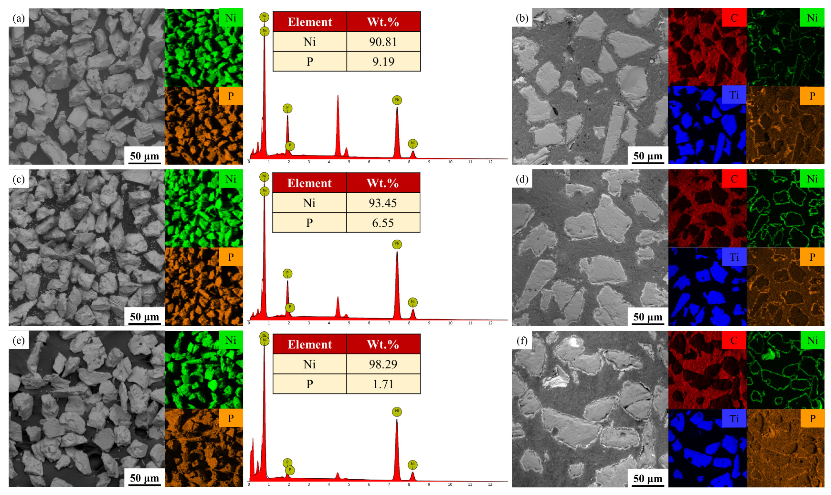
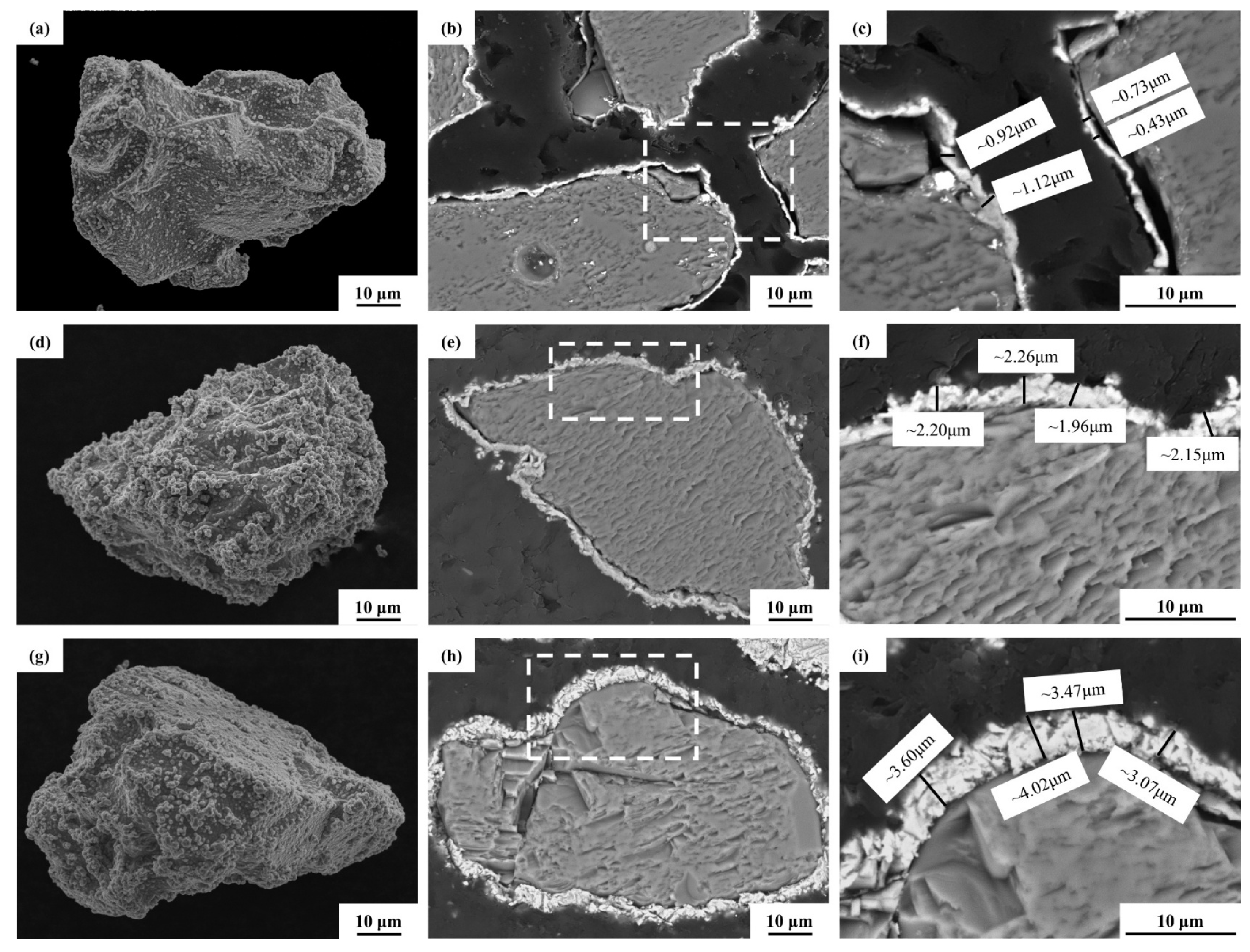
3.1. Metallization of TiC Ceramic Surface

Figure 2a,c,e show the EDS scan results for the three metallized ceramic surfaces—HP (high-phosphorus content), MP (medium-phosphorus content), and LP (low-phosphorus content)—which reveal a uniform distribution of Ni and P. This is consistent with the Ni-P co-deposition characterization. The average phosphorus contents for the HP, MP, and LP surfaces were 9.19 wt.%, 6.55 wt.%, and 1.71 wt.%, respectively. The EDS analysis of the cross-section in Figure 2b,d,f provides a clearer view of the elemental distribution. As illustrated in Figure 2 and shown in Table 1, variations in the phosphorus-reducing salt content and the complex buffer pair significantly affect the P element content in the Ni-P plating.
The concentrations of NaH2PO2·H2O in the HP and MP plating solutions were 60 g/L and 27 g/L, respectively. NaKC4H4O6 + C6H5Na3O7 and NH4Cl + C6H5Na3O7 were used as complexing buffers, reducing the amount of phosphorus-reducing salt by approximately fifty percent while decreasing the phosphorus content on the surface of the metallized TiC plating by less than three percent. Nonetheless, metallized TiC with a comparatively elevated P content can be obtained. The concentration of phosphorus-reducing salt in the LP plating solution was 15 g/L. When C4H4Na2O4 and C6H5Na3O7 were used as a complexing buffer, the phosphorus concentration in the nickel-phosphorus plating on the surface of metallized TiC was merely 1.7 wt.%. The structure of the primary coordination compound, when it was a cyclic chelate or incorporated a carboxyl group, facilitated the attainment of Ni-P plating with elevated phosphorus concentration. Moreover, succinic acid readily bound with nickel ions to form an unstable seven-membered ring chelate, which failed to significantly enhance the phosphorus content in Ni-P plating [27].
According to the chemical plating Ni-P reaction, the overall reaction equation can be as follows [28]:
2 [ Ni 2 + + ml n ] + 8 H 2 P O 2 + 2 H 2 O     6 H 2 P O 3 + 2 H + + 3 H 2 + 2 P + 2 Ni + 2 ml n
where [ Ni 2 + + ml n ] represents the nickel complex, and ml n represents the free complexing agent. According to the reaction formula, the concentration of H +   increases as the reaction proceeds. Therefore, the pH value of the plating solution decreases as the chemical plating reaction proceeds. The nickel deposition rate increases as the H +   concentration decreases (i.e., as the pH value increases).
In order to further illustrate the effect of phosphorus concentration on the surface plating of the three metallized TiC particles, surface observations were made on the loose particles of the metallized TiC samples, and cross-sectional observations were made on the resin-embedded particles after metallographic polishing. Table 3 presents an analysis of the energy spectrum, including the elemental composition and thickness distribution of Ni-P plating at three distinct phosphorus concentrations. Figure 3a shows the surface of HP-metallized TiC, characterized by a low number of nodule particles and a relatively smooth and flat texture. Figure 3b shows that the HP plating can be applied uniformly to the TiC surface with no coverage deficiencies. Figure 3c shows that the plating predominantly has a thickness ranging from 0.8 ± 0.25 µm. Figure 3d shows the surface of MP metallized TiC, which has a cauliflower-like structure and a higher number of Ni-P nodule particles. Figure 3e illustrates that the MP plating can be applied uniformly to the TiC surface. As shown in Figure 3f, the plating thickness predominantly measures 2.1 ± 0.11 µm. The surface of LP metallized TiC, depicted in Figure 3g, has a cauliflower morphology characterized by an abundance of Ni-P nodule particles and a uniform coating. Figure 3i shows that the plating thickness predominantly measures 3.5 ± 0.34 µm. Regulation of the HP bath at a low pH is aimed at inhibiting the destabilization caused by excess sodium hypophosphite [29]. According to the aforementioned equation, the HP bath had a pH value of 4.7, indicating a high concentration of hydrogen ions, which led to a reduced reaction rate. In contrast, the MP and LP plating solutions had elevated pH values, resulting in an accelerated Ni deposition rate and increased plating thickness. The coating on the metallized TiC surface generated by the LP plating solution was the most substantial. This is due to succinic acid’s ability to readily couple with nickel ions to form an unstable seven-membered ring chelate. This increases the concentration of free nickel ions, thereby accelerating the chemical plating reaction rate [30].
The XRD spectrum of the chemically deposited nickel plating shows a prominent peak at around 2θ = 45°, which was identified as Ni-P plating [31,32]. Figure 4 shows the XRD spectra of three metallized ceramics. LP and MP metallized TiC exhibit diffraction peaks at θ = 44.5°, which correspond to the (111) Ni crystal plane in the Ni-P coating. MP metallized TiC shows a broad diffraction peak for Ni (111), indicating a disordered atomic arrangement. In contrast, the diffraction peak of LP metallized TiC is sharp and pronounced, demonstrating superior crystallinity compared to the former [33]. LP metallized ceramics exhibit a diffraction peak for Ni at 52°, signifying the highest degree of Ni-P crystallization. In contrast, HP metallized ceramics show no associated diffraction peaks for Ni. This behavior is attributed to the crystal transformation induced by variations in phosphorus content within the Ni-P plating. As the phosphorus level decreases, the crystallinity of the Ni-P plating increases [34]. Low phosphorus concentrations yield microcrystalline Ni-P plating, while intermediate phosphorus values result in plating comprising both crystalline and amorphous phases. High phosphorus levels generate a shielding effect, resulting in a fully amorphous chemical Ni-P plating [35].

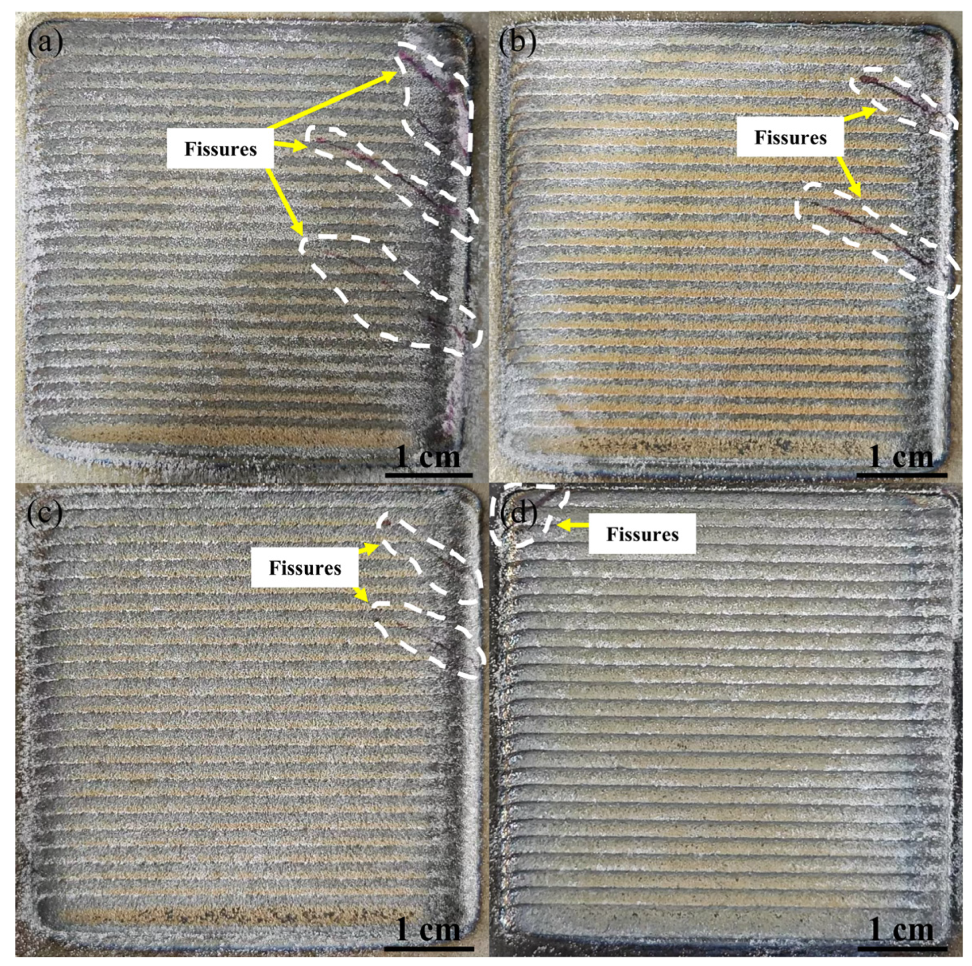
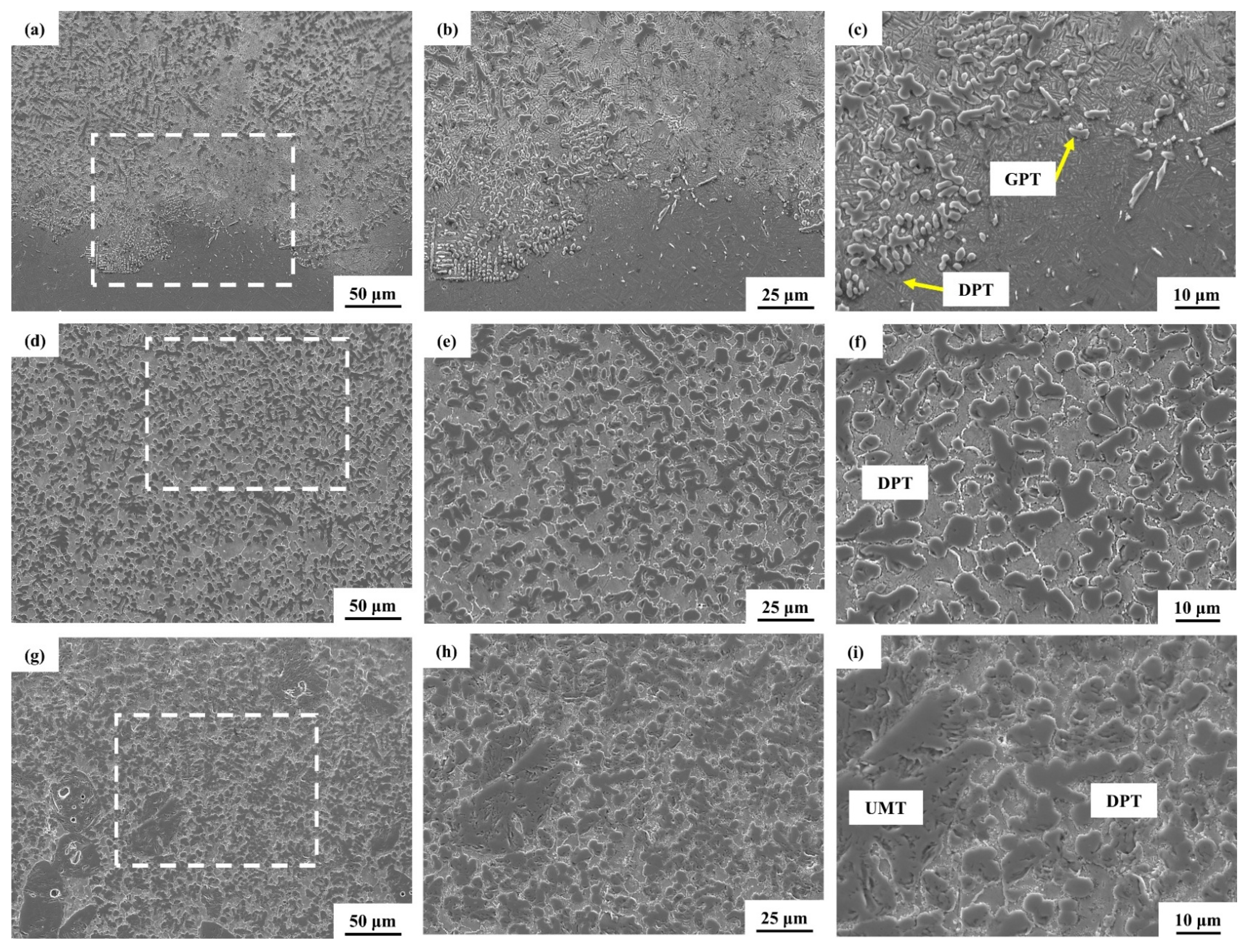
3.2. Laser Melting Deposition of TiC-Ti6Al4V

Untreated TiC and three metallized TiC variants (HP, MP, and LP) produced using the preceding chemical deposition method served as reinforcements for 50 wt.% TiC-Ti6Al4V composite coatings. The synthesized TiC-reinforced titanium matrix composite coatings were designated as TMC-Nickel-free, TMC-HP, TMC-MP, and TMC-LP. Figure 5 shows the surface macromorphology and penetration test results of the coatings. The golden surface appearance is attributed to TiN and Ti2N. The red line denotes surface fissures, while the white deposits represent the remnants of the developer. The surfaces of the four coatings exhibit uniformity, continuity, and density, without signs of over-burning or wrinkling. The red development line indicates that cracks emerged in the upper sections of the four coatings, caused by premature processing and rapid cooling in that region. Fractures are visible in the central regions of TMC-Nickel-free and TMC-HP (Figure 5a,b), while there are negligible fractures in the central and lower sections of TMC-MP and TMC-LP (Figure 5c,d). These fissures often form at an angle of approximately 45° to the laser scanning direction. This is primarily due to the accumulation and redistribution of thermal stress induced by the intersection of various processing tracks. During single-pass laser processing, cracks are generally oriented perpendicular to the laser scanning direction. Furthermore, the stress within the coating exceeds its ultimate tensile strength, which also contributes to the formation of cracks [36]. Brittle cladding coatings, characterized by high ceramic content and limited deformability, readily facilitate fracture initiation. TiC powders modified by Ni-P chemical plating can reduce defects in composite coatings by improving metallurgical bonding at the interface and reducing stress concentration. As Li Q et al. [37] noted, this may be attributable to the fact that the dissolution of the Ni coating in the presence of the laser releases nickel into the molten pool, thus limiting unwanted interfacial reactions. Metallization reduces the formation of brittle compounds and relieves carbide-induced stress concentrations, thereby reducing the rate of crack formation.
As illustrated in Figure 6, the results of X-ray diffraction measurements for the four composite coatings reveal their primary phase constituents. The detected phases include α-Ti, β-Ti, Ti2Ni, and TiC. The addition of various metallized TiC types has been shown to cause negligible alteration in the diffraction peak positions. It was established that no additional carbides or compounds were detected. At elevated laser power, a significant quantity of TiC ceramic particles melted, while free carbon elements did not interact with AI, V, and Ni to form new compounds. Despite the XRD patterns of each sample exhibiting a comparable profile and the phase types remaining largely unchanged with respect to the TiC type, slight variations in the composition of individual phases were observed. The gradual enhancement of the Ti2Ni diffraction peaks at 41.2° and 45° during the transition from TMC nickel-free to TMC-LP is consistent with the findings of the energy spectrum analysis presented in Table 4. However, it is important to note that the intensity of the β-Ti diffraction peak diminishes. The solid solubility of Ni in β-Ti (14.3 wt.%) is significantly higher than in α-Ti (0.3 wt.%). Elements that promote eutectic formation can lower the β to the α/α′ phase-transition temperature [38,39].
Figure 7, Figure 8, Figure 9 and Figure 10 present SEM micrographs of four distinct coatings after etching. The black phase is uniformly integrated inside the light phase, and the attributes of the black phase are fundamentally identical. Figure 11 illustrates the energy dispersive spectroscopy (EDS) examination of the central region of the four coatings. The energy spectrum study indicates that the dark phase predominantly comprises Ti and C, which are identified as TiC [40]. Variations in coating regions result in distinct temperature gradients (G) and solidification rates (R). Upon cooling and solidification of the molten liquid pool, TiC phases exhibiting various morphologies are generated. Four distinct forms of resolidified TiC precipitates exist: chained primary TiC (CPT), granular primary TiC (GPT), dendritic primary TiC (DPT), and unmelted TiC (UMT). These phases are pivotal in causing microstructural variations [41]. The morphology of TiC is determined by the G/R ratio, while the dimensions of TiC are influenced by the cooling rate (G × R) during the process of solidification. Elevated G/R values lead to the expansion of the supercooled structure at the solid–liquid interface, thereby augmenting the segregation of carbon elements and facilitating the development of dendritic TiC. Conversely, diminished G × R values allow adequate time for TiC growth, culminating in the formation of coarser TiC [42]. During the solidification process, the bottom section of the coating cools more rapidly, resulting in a greater degree of undercooling and a significantly lower TiC concentration. Consequently, the TiC in this region consists primarily of a fine DPT phase and a fine GPT phase. It has been demonstrated that specific TiC particles with a certain degree of granularity exhibit CPT, with the predominant distribution being eutectic TiC [43]. The central and superior sections of the coating exhibit reduced heat dissipation, resulting in a diminished G/R value and a decreased G × R product. Consequently, the central section is predominantly comprised of a coarse GPT phase. The TiC phase in the upper section of the coating primarily comprises a coarse GPT phase and an UMT phase. The presence of additional unmelted phases in the coatings may be attributed to the faster processing speed and sharp temperature gradient as well as the rather high TiC content (50 wt.%). The density of TiC is slightly lower than that of titanium alloys, resulting in some of the incompletely melted TiC being concentrated at the top of the coating. However, the buoyancy and gravitational forces acting on the TiC particles compete dynamically in the Marangoni flow of the melt pool, in which case there is little large-scale aggregation of TiC [44,45]. It is noteworthy that certain UMTs exhibit a measurement of less than 40 μm, thereby suggesting that a proportion of the initial TiC particles may have undergone a process of partial melting or dissolution. Despite the variation in shape, the boundaries of the UMTs are characterized by the absence of distinct sharp corners. Furthermore, the UMTs display a distinct interface with the Ti6Al4V matrix, exhibiting no apparent flaws such as pores and fissures.

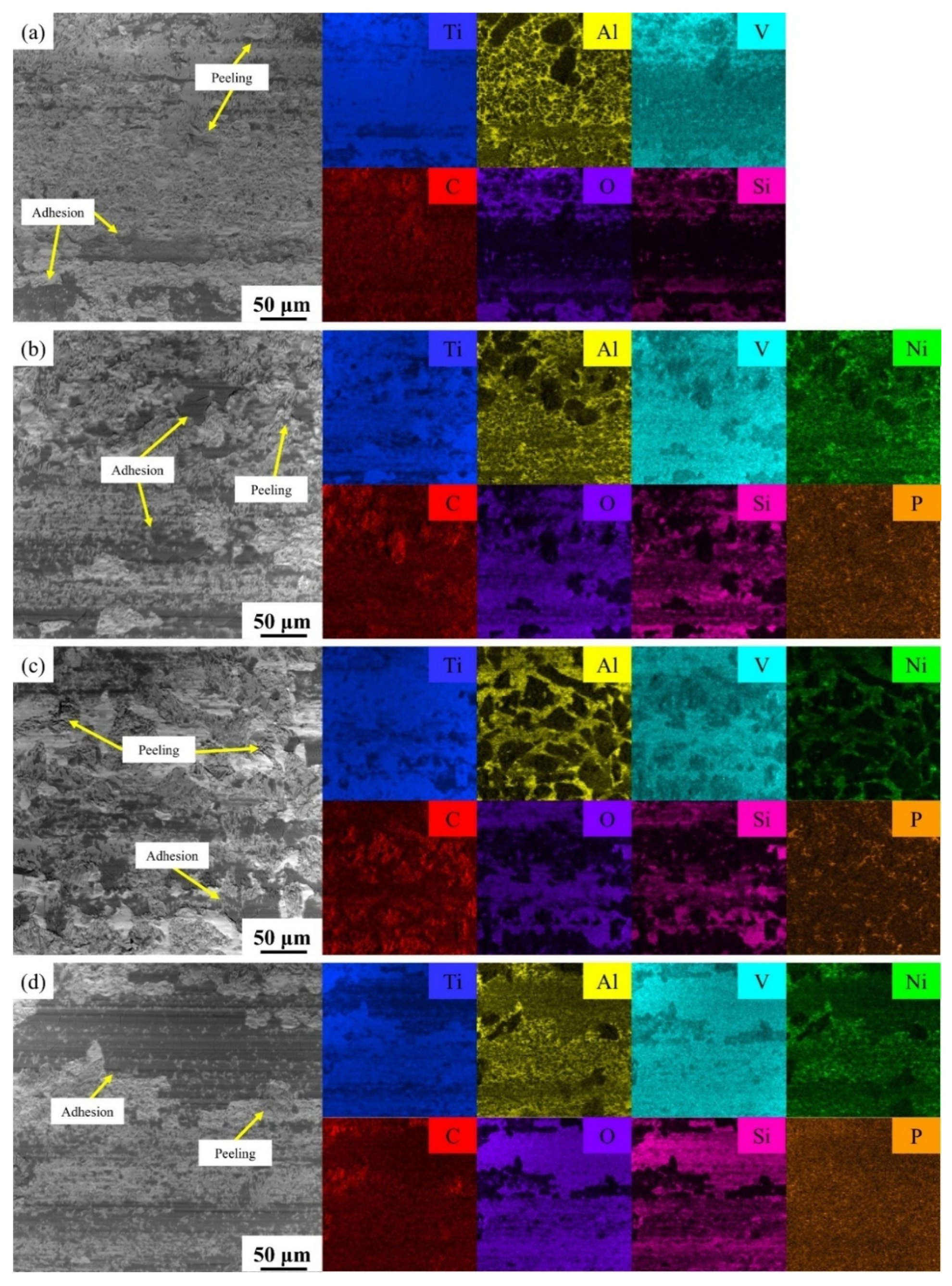
3.3. Hardness and Tribological Properties

As shown in Figure 12, the hardness of the coating increases gradually as the number of primary TiC phases increases [46]. Figure 13a shows the distribution of microhardness values for the four coatings. These values range from 720 HV0.5 to 1130 HV0.5. The microhardness of the coatings increases gradually from the transition layer to the surface and is much higher than that of the Ti6Al4V matrix. Generally, an increase in microhardness is related to the composite’s microstructure. As can be seen from the microstructure images in Figure 7, Figure 8, Figure 9 and Figure 10, the distribution of the primary TiC phases from the bottom to the top of the coating corresponds to an increase in the microhardness gradient of the coating cross-section. Additionally, a TiC content of 50 wt.% results in a large number of free carbon atoms being released during the melting process. These can form carbon solid solution strengthening and fine grain strengthening, thereby contributing to an increase in hardness [47].
The top hardness of TMC-Nickel-free, TMC-HP, TMC-MP, and TMC-LP was 1076.63 ± 20.59 HV0.5, 1068.73 ± 19.91 HV0.5, 1129.2 ± 23.65 HV0.5, and 1111.43 ± 14.46 HV0.5, respectively. According to the energy spectrum analysis results shown in Figure 11, the nickel element is uniformly distributed within the coating. The XRD pattern in Figure 6 shows that forming hard Ti2Ni from nickel and titanium can increase the hardness of the coating [48]. The surface coating thickness of the three metallized TiC is uneven, and the amount of Ni in the coatings varies. The TiC phases are more concentrated at the top, resulting in relatively high hardness at the top of TMC-MP and TMC-LP. It is worth noting that the hardness trend does not show a linear increase; more fluctuations are observed, which may be due to the gradual increase and coarsening of the ceramic phase from bottom to top. A large number of ceramic particles can easily lead to indentation interactions at the ceramic/substrate interface, causing fluctuations in the hardness of these composites [49], which can be observed in the indentations in Figure 12. Additionally, the presence of high concentrations of unfused phases in the upper part of the coating, coupled with potential interfacial bonding issues, can also result in variations in hardness [50]. As shown in Figure 13a, the TMC-Nickel-free and TMC-HP coatings are harder in some areas. According to the previous defect test shown in Figure 5, metallization relieves residual internal stresses and thus reduces cracking. Therefore, the presence of higher residual stresses in localized areas of the TMC-Nickel-free and TMC-HP coatings may have contributed to the increase in hardness [51].
To ensure the robustness of the test, the representative friction coefficients (COF) shown in Figure 13b were selected to be closest to the average friction coefficients shown in Figure 13c. The friction coefficients of the four coatings exhibited a consistent trend. During the running-in period, the friction coefficient fluctuated significantly due to shear tearing between the friction pair and the material. Initially, the friction coefficient increased dramatically, then decreased, and approached dynamic equilibrium, entering the steady wear phase. The coefficients of friction of TMC-Nickel-free, TMC-HP, and TMC-LP underwent a sharp increase during friction, followed by a return to stability. This behavior may be attributed to the exfoliation of particles of incompletely melted TiC, which alters the wear conditions. The subsequent occurrence of abrasive and adhesive wear, as a result, has been shown to increase frictional resistance, leading to a substantial rise in the coefficient of friction. The application of a reciprocating force resulted in the removal of abrasive debris and the smoothing of the wear surface, thus returning it to its original state and thereby stabilizing the coefficient of friction [52]. From Figure 13c, the average friction coefficients for TMC-Nickel-free, TMC-HP, TMC-MP, and TMC-LP are 0.454, 0.415, 0.411, and 0.404, respectively. This indicates that altering the surface metallization of TiC can decrease the friction coefficient of the composite coating. As shown in Figure 13c, the average wear rates for TMC-Nickel-free, TMC-HP, TMC-MP, and TMC-LP are 3.56 × 10⁻⁵ mm3/(Nm), 2.77 × 10⁻⁵ mm3/(Nm), 2.03 × 10⁻⁵ mm3/(Nm), and 1.00 × 10⁻⁵ mm3/(Nm), respectively. This suggests that Ni-P metallization on the surface of TiC improves the wear resistance of composite coatings, with TMC-LP demonstrating the greatest resistance. Figure 13d and Figure 14 show a representative contour map of the abrasion marks and a representative 3D morphology map of the abrasion marks, respectively. These figures show that the width and depth of the wear scar align with the wear rate variation depicted in Figure 12c. Specifically, TMC-LP exhibits the smallest width and depth of the wear scar, corresponding to the lowest wear rate. This further confirms the superior wear resistance of TMC-LP.
The abrasion resistance of a coating is directly related to its hardness, and the higher surface hardness of TMC-MP and TMC-LP gives them a high resistance to wear. TMC-MP and TMC-LP produced fewer cracks in the flaw test (Figure 5), and TMC-LP only appeared in the initial stage of processing, which represents the excellent combination of materials in TMC-LP, therefore showing the lowest wear rate in the reciprocating friction test.
TMC-Nickel-free and TMC-HP have poor bonding due to large internal residual stresses and the effect of insufficient wetting modification. The ceramic flakes off when the coating is subjected to impact, resulting in excessive adhesive and abrasive wear, which contributes to the increase in wear rate [53]. However, according to the number of cracks in Figure 5, it can be inferred that the bonding degree of different phases inside TMC-HP is better than that of TMC-Nickel-free, so its wear rate is smaller.
Figure 15 shows the shape and elemental composition analysis of the central region of the coating wear scar after the dry sliding wear test in order to investigate the wear process of the coating. The delamination and adherence of black SiC grinding balls on the worn surface indicate characteristic adhesive wear. TiC predominantly exists as minute particles that enhance the wear resistance of the coating. The coated surface is smooth, without significant debris or grooves, which is indicative of abrasive wear. The presence of plowing grooves is generally imperceptible throughout the friction and wear process. The dispersion of the high-hardness TiC phase in the coating inhibits the micro-cutting effect. The primary wear mechanisms are abrasive wear, adhesive wear, and oxidative wear, with no evidence of plastic deformation or cracks on the worn surface.
It is important to note that the surface displayed in Figure 15b–d exhibits a significant number of black abrasive ball adhesions. This phenomenon indicates that it has excellent anti-wear efficacy on the friction partner. Concurrently, a minimal number of spalling pits are discernible on the surface of the TMC-LP. The enhanced smoothness of the wear surface facilitates the attainment of superior anti-wear performance [54], as evidenced by the lowest average COF and lowest average exhibited in Figure 13c. The high coefficient of friction is attributable to two main factors: the accumulation of abrasive debris and the presence of rough wear surfaces [55]. As demonstrated in Figure 15a, the wear surface of TMC-Nickel-free exhibits the most significant flaking pits, thereby justifying its notably elevated average coefficient of friction as illustrated in Figure 13c. TMC-MP and TMC-LP also exhibit rough wear surfaces, and their average coefficients of friction are shown in Figure 13c. However, both are smaller than the average coefficients of friction of TMC-Nickel-free. This suggests that Ni-P metallization promotes the bonding of the ceramic phase with the metal to a certain extent. Furthermore, the presence of a number of spalling pits indicates that the bonding of the ceramic phase to the metal matrix remains inadequate, thereby suggesting the presence of substantial residual stresses within the structure.
The results of the friction tests demonstrate that Ni-P metallization on the surface of TiC particles enhances its wettability with titanium alloys, thereby improving the wear resistance of the composite coatings. The extent of this effect varies with the phosphorus content, and LP metallization has the optimal effect of wetting modification.

4. Conclusions

Metallized TiC powders with high--, middle, and low-phosphorus contents were prepared by Ni-P chemical plating. These powders were then used as reinforcement materials to produce 50 wt.% TiC-Ti6Al4V titanium matrix composites via laser melting deposition. Examination of the microstructure and mechanical properties of these coatings led to the following conclusions:
(1)
Three metallized TiC samples with varying phosphorus concentrations were generated by altering chemical deposition formulations and processes. This resulted in surface plating thicknesses of 0.9 ± 0.2 µm, 2 ± 0.2 µm, and 3.5 ± 0.5 µm, respectively. The properties of the plating were significantly influenced by the phosphorus content. The surface plating of LP metallized ceramics was the thickest and exhibited the highest crystallinity, and it was characterized as microcrystalline;
(2)
Using untreated TiC and three metallized TiC variants combined with Ti6Al4V can produce coatings with consistent, continuous, dense, and non-overburned surfaces. The results demonstrate that the use of metallized TiC as a reinforcement reduced the occurrence of cracks. Specifically, TMC-MP and TMC-LP exhibited fewer cracks, with TMC-LP only showing cracks in the initial stage of processing;
(3)
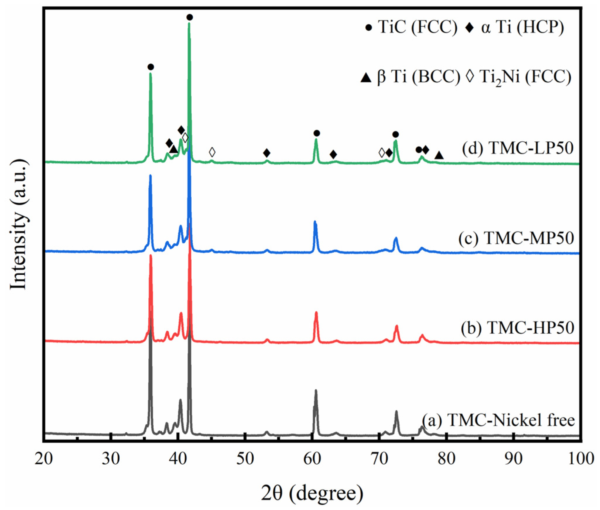
The microhardness distribution of the coatings ranged from 720 HV0.5 to 1130 HV0.5. TMC-MP and TMC-LP exhibited a higher concentration of nickel, which contributes to the formation of robust Ti2Ni intermetallic compounds within the coating, resulting in a somewhat elevated microhardness. The primary wear processes of the four coatings include abrasive wear, adhesive wear, and oxidative wear. The average friction coefficients and wear rates were as follows: TMC-LP < TMC-MP < TMC-HP < TMC-Nickel-free. Ni-P metallization on the TiC surface can improve its wettability with Ti6Al4V, thereby enhancing the wear resistance of composite coatings. LP metallization was the most effective.
The metallization process increases the manufacturing cost of the coating, and the cumbersome process flow and additional process cost are not applicable to the civil field. However, the improved abrasion resistance and interface reinforcement effect brought by the metallization process still have irreplaceable advantages in the key components of high-end equipment.

Author Contributions

Y.W., data curation, formal analysis, investigation, writing—original draft, and visualization; Y.Y., supervision; J.L., supervision; C.Y., validation; X.D., investigation; H.Z., supervision; D.C., funding acquisition; W.L., validation; Q.W., conceptualization, resources, supervision, and funding acquisition; P.Z., conceptualization, methodology, resources, supervision, and writing—review and editing. All authors have read and agreed to the published version of the manuscript.

Funding

This study was funded by the Guangdong Province Key Research and Development Programme (No. 2023B0909020002) and National Key Research and Development Program of China (No. 2023YFB3408200).

Institutional Review Board Statement

Not applicable.

Informed Consent Statement

Not applicable.

Data Availability Statement

Data will be made available on request.

Conflicts of Interest

Author Xinwei Du was employed by the company Ruyuan Dongyangguang UACJ Fine Foil Co., Ltd. Author Hu Zhao was employed by the company GD Midea Air-Conditioning Equipment Co., Ltd. The remaining authors declare that the research was conducted in the absence of any commercial or financial relationships that could be construed as a potential conflict of interest.

References

  1. Revankar, G.D.; Shetty, R.; Rao, S.S.; Gaitonde, V.N. Wear resistance enhancement of titanium alloy (Ti–6Al–4V) by ball burnishing process. J. Mater. Res. Technol. 2017, 6, 13–32. [Google Scholar] [CrossRef]
  2. Philip, J.T.; Mathew, J.; Kuriachen, B. Tribology of Ti6Al4V: A Review. Friction 2019, 7, 497–536. [Google Scholar] [CrossRef]
  3. Ren, Z.Y.; Hu, Y.L.; Tong, Y.G.; Cai, Z.H.; Liu, J.; Wang, H.D.; Liao, J.Z.; Xu, S.; Li, L.K. Wear-resistant Nb Mo Ta W Ti high entropy alloy coating prepared by laser melting deposition technology on TC4 titanium alloy. Tribol. Int. 2023, 182, 108366. [Google Scholar] [CrossRef]
  4. Zhang, G.; Tang, J.; Yang, K.; Wang, R.; Chen, Y.; Xiong, Y.; Wu, C.; Li, Z.; Wang, Y.; Lin, H. Important contributions of metal interfaces on their tribological performances: From influencing factors to wear mechanisms. Compos. Struct. 2024, 337, 118027. [Google Scholar] [CrossRef]
  5. He, X.; Song, R.G.; Kong, D.J. Effects of TiC on the microstructure and properties of TiC/TiAl composite coating prepared by laser melting deposition technology. Opt. Laser Technol. 2019, 112, 339–348. [Google Scholar] [CrossRef]
  6. Mahamood, R.M.; Akinlabi, E.T.; Shukla, M.; Pityana, S. Scanning velocity influence on microstructure, microhardness and wear resistance performance of laser deposited Ti6Al4V/TiC composite. Mater. Des. 2013, 50, 656–666. [Google Scholar] [CrossRef]
  7. Cui, W.; Li, Y.; Li, F.; Qi, X.; Sun, X.; Pan, Z.; Niu, J. Wear and corrosion properties of in-situ TiC–TiB2 modified Ni-based composite coatings with different B/C ratios prepared by laser melting deposition technology. Ceram. Int. 2024, 50, 2424–2435. [Google Scholar] [CrossRef]
  8. Cai, Q.; Li, G.; Wu, B.; Xu, S.; Wang, L.; Guo, Y. Effect of TiC content on microstructure and properties of TiC/Ni60 coatings on Ti6Al4V alloy deposited by laser melting deposition technology. Opt. Laser Technol. 2024, 168, 109854. [Google Scholar] [CrossRef]
  9. Zhang, Y.; Chen, Y.K.; Yu, D.S.; Sun, D.Q.; Li, H.M. A review paper on effect of the welding process of ceramics and metals. J. Mater. Res. Technol. 2020, 9, 16214–16236. [Google Scholar] [CrossRef]
  10. Wu, L.; Meng, L.; Wang, Y.; Zhang, S.; Bai, W.; Ouyang, T.; Lv, M.; Zeng, X. Effects of laser surface modification on the adhesion strength and fracture mechanism of electroless-plated coatings. Surf. Coat. Technol. 2022, 429, 127927. [Google Scholar] [CrossRef]
  11. Salicio-Paz, A.; Dalmau, A.; Grande, H.; Iriarte, A.; Sort, J.; Pellicer, E.; Fornell, J.; García-Lecina, E. Impact of the multilayer approach on the tribocorrosion behaviour of nanocrystalline electroless nickel coatings obtained by different plating modes. Wear 2020, 456, 203384. [Google Scholar] [CrossRef]
  12. Shen, Y.; Guo, J.; Wang, L.; Han, H.; Ma, Y.; Xin, B.; Wang, Z. Acceleration Mechanism of Triethanolamine in Electroless Bath for Pure Cobalt Deposition. J. Electrochem. Soc. 2023, 170, 112503. [Google Scholar] [CrossRef]
  13. Wang, S.; Sun, Y.; Li, G. Study on cobalt coating on ZTA particles by electroless plating and impact-abrasive wear behavior of ZTAp reinforced iron matrix composite. Wear 2022, 510, 204489. [Google Scholar] [CrossRef]
  14. Sun, P.; Dong, Z.; Chen, Y.; Yan, H.; Luo, C.; Song, H.; Hu, Z. Characterization of Ni coating layer of Al2O3 particles and their wettability behavior in Al2O3@ Ni/Al-10Si composites. Appl. Surf. Sci. 2020, 526, 146660. [Google Scholar] [CrossRef]
  15. Li, C.; Goei, R.; Li, Y.; Shi, J.; Li, B.; Liu, F.; Li, Y.; Gao, Y.; Li, S.; Zhao, S.; et al. Fabrication and wear property of NiCo coated ZrO2–Al2O3 ceramic particles reinforced high manganese steel-based composites. Wear 2022, 492, 204235. [Google Scholar] [CrossRef]
  16. Lou, M.; Chen, L.; Xu, K.; Zhang, G.; Chang, K. Tribocorrosion of TiC-based composites incorporating Ni and Co binders in saline solutions. Int. J. Refract. Hard Met. 2024, 119, 106519. [Google Scholar] [CrossRef]
  17. Liu, Y.; Yang, Y.; Chen, C. Microstructure and properties of Ni-Ti based gradient laser melting deposition technology layer of Ti6Al4V alloy by laser powder bed fusion. Addit. Manuf. 2024, 79, 103906. [Google Scholar]
  18. Huang, Z.; Nguyen, T.; Zhou, Y.; Qi, G. A low temperature electroless nickel plating chemistry. Surf. Coat. Technol. 2019, 372, 160–165. [Google Scholar] [CrossRef]
  19. Zhang, Y.; Zhang, T.; Shi, H.; Liu, Q.; Wang, T. Fabrication of flexible copper patterns by electroless plating with copper nanoparticles as seeds. Appl. Surf. Sci. 2021, 547, 149220. [Google Scholar] [CrossRef]
  20. Sha, W.; Wu, X.M.; Sarililah, W. Scanning electron microscopy study of microstructural evolution of electroless nickel–phosphorus deposits with heat treatment. Mater. Sci. Eng. B 2010, 168, 95–99. [Google Scholar] [CrossRef]
  21. Chow, Y.M.; Lau, W.M.; Karim, Z.S. Surface properties and solderability behaviour of nickel–phosphorus and nickel–boron deposited by electroless plating. Surf. Interface Anal. 2001, 31, 321–327. [Google Scholar] [CrossRef]
  22. Xiao, J.; Wang, F.; Li, J.; Chen, Z. Comparison of interfacial reactions and isothermal aging of cone Ni-P and flat Ni-P with Sn3.5Ag solders. Appl. Surf. Sci. 2023, 625, 157219. [Google Scholar] [CrossRef]
  23. Wu, M.; He, X.; Rafi-ud-Din; Ren, S.; Qin, M.; Qu, X. Effect of P and aging on microstructure and shear strength of Sn–2.5 Ag–2.0 Ni/Ni (P) solder joints. Mater. Chem. Phys. 2010, 121, 259–266. [Google Scholar] [CrossRef]
  24. Boakye, G.O.; Straume, E.O.; Kovalov, D.; Karlsdottir, S.N. Wear-reducing nickel-phosphorus and graphene oxide-based composite coatings: Microstructure and corrosion behavior in high temperature geothermal environment. Corros. Sci. 2022, 209, 110809. [Google Scholar] [CrossRef]
  25. He, P.; Huang, S.; Wang, H.; Huang, Z.; Hu, J.; Cheng, X.; Pan, C. Electroless nickel–phosphorus plating on silicon carbide particles for metal matrix composites. Ceram. Int. 2014, 40, 16653–16664. [Google Scholar] [CrossRef]
  26. Ye, Y.; Yang, J.; He, M.; Wang, Q.; Li, J.; Zhang, P.; Tu, X.; Li, W. Microstructural and wear resistance evolution of Alx (TiVZr) 100− x lightweight high-entropy alloys. Tribol. Int. 2024, 195, 109585. [Google Scholar] [CrossRef]
  27. Cui, G.; Li, N.; Li, D.; Chi, M. Study of optimized complexing agent for low-phosphorus electroless nickel plating bath. J. Electrochem. Soc. 2005, 152, C669. [Google Scholar] [CrossRef]
  28. Hu, B.; Sun, R.; Yu, G.; Liu, L.; Xie, Z.; He, X.; Zhang, X. Effect of bath pH and stabilizer on electroless nickel plating of magnesium alloys. Surf. Coat. Technol. 2013, 228, 84–91. [Google Scholar] [CrossRef]
  29. Wang, Y.; Chen, T.; Zhang, R. Electroless deposition of NiMoP coating on Q235B steel and its Corrosion Resistance in Simulated Concrete Pore Solution. Int. J. Electrochem. Sci. 2023, 18, 100313. [Google Scholar]
  30. Shartal, K.M.; Kipouros, G.J. Electroless nickel phosphorus plating on AZ31. Met. Mater. Trans. B 2009, 40, 208–222. [Google Scholar] [CrossRef]
  31. Cui, C.; Du, H.; Liu, H.; Xiong, T. Corrosion behavior of the electroless Ni-P coating on the pore walls of the lotus-type porous copper. Corros. Sci. 2020, 162, 108202. [Google Scholar] [CrossRef]
  32. Yu, Q.; Zhou, T.; He, Y.; Liu, P.; Wang, X.; Jiang, Y.; Yan, J. Annealed high-phosphorus electroless Ni–P coatings for producing molds for precision glass molding. Mater. Chem. Phys. 2021, 262, 124297. [Google Scholar] [CrossRef]
  33. Tian, M.; Jian, Z.; Hai, R. Preparation and properties of thick nickel-phosphorus amorphous plating on SiCp/Al composite by double zincate pretreatment. J. Alloys Compd. 2022, 909, 164806. [Google Scholar] [CrossRef]
  34. Lelevic, A.; Walsh, F.C. Electrodeposition of NiP alloy coatings: A review. Surf. Coat. Technol. 2019, 369, 198–220. [Google Scholar] [CrossRef]
  35. Martyak, N.M.; Drake, K. Peak-profile analysis of electroless nickel coatings. J. Alloys Compd. 2000, 312, 30–40. [Google Scholar] [CrossRef]
  36. Zhou, Z.Y.; Liu, X.B.; Zhuang, S.G.; Yang, X.H.; Wang, M.; Sun, C.F. Preparation and high temperature tribological properties of laser in-situ synthesized self-lubricating composite coatings containing metal sulfides on Ti6Al4V alloy. Appl. Surf. Sci. 2019, 481, 209–218. [Google Scholar] [CrossRef]
  37. Li, Q.; Cui, J.; Yang, Y.; Zhao, Y.; Yu, C.; Wang, Q.; Zhang, P. Enhanced surface wettability modification of Al2O3 for laser cladding ceramic-metal composite coatings. Mater. Today Commun. 2024, 40, 109746. [Google Scholar] [CrossRef]
  38. Garay, J.E.; Anselmi-Tamburini, U.; Munir, Z.A. Enhanced growth of intermetallic phases in the Ni–Ti system by current effects. Acta Mater. 2003, 51, 4487–4495. [Google Scholar] [CrossRef]
  39. Xiong, Z.; Pang, X.; Liu, S.; Li, Z.; Misra, R.D.K. Hierarchical refinement of nickel-microalloyed titanium during additive manufacturing. Scr. Mater. 2021, 195, 113727. [Google Scholar] [CrossRef]
  40. Chen, L.; Yu, T.; Guan, C.; Zhao, Y. Microstructure and properties of metal parts remanufactured by laser cladding TiC and TiB2 reinforced Fe-based coatings. Ceram. Int. 2022, 48, 14127–14140. [Google Scholar] [CrossRef]
  41. Zhang, J.; Wang, L.; Zhao, K.; Qi, C.; Shi, B.; Zhang, Y.; Yuan, S.; Zhan, X. Thermal analysis and microstructure evolution of TiC/Ti6Al4V functionally graded material by direct energy deposition. Mater. Sci. Eng. A 2024, 893, 146136. [Google Scholar] [CrossRef]
  42. Zheng, Y.; Yan, X.; Qiao, G.; Tang, Y.; Geng, Y.; Shao, Z.; Bai, Q. Enhanced wear resistance of TiC/Ti6Al4V composites through changing TiC morphologies in laser direct energy deposition. Addit. Manuf. 2024, 84, 104134. [Google Scholar] [CrossRef]
  43. Tang, M.; Zhang, L.; Zhang, N. Microstructural evolution, mechanical and tribological properties of TiC/Ti6Al4V composites with unique microstructure prepared by SLM. Mater. Sci. Eng. A 2021, 814, 141187. [Google Scholar] [CrossRef]
  44. Liu, S.; Shin, Y.C. The influences of melting degree of TiC reinforcements on microstructure and mechanical properties of laser direct deposited Ti6Al4V-TiC composites. Mater. Des. 2017, 136, 185–195. [Google Scholar] [CrossRef]
  45. Ma, G.; Yu, C.; Tang, B.; Li, Y.; Niu, F.; Wu, D.; Bi, G.; Liu, S. High-mass-proportion TiCp/Ti6Al4V titanium matrix composites prepared by directed energy deposition. Addit. Manuf. 2020, 35, 101323. [Google Scholar] [CrossRef]
  46. Li, L.; Wang, J.; Lin, P.; Liu, H. Microstructure and mechanical properties of functionally graded TiCp/Ti6Al4V composite fabricated by laser melting deposition. Ceram. Int. 2017, 43, 16638–16651. [Google Scholar] [CrossRef]
  47. Zhang, F.; Deng, Y.; Zhou, X.; Wang, G.; Wang, Y.; Wang, M.; Tan, H. Effect of C addition on microstructure and mechanical properties of laser micro-alloying Ti–Al–V–C titanium matrix composites. J. Mater. Res. Technol. 2022, 20, 147–156. [Google Scholar] [CrossRef]
  48. Su, Y.Y.; Wang, Z.F.; Xie, J.C.; Xu, G.; Xing, F.; Luo, K.Y.; Lu, J.Z. Microstructures and mechanical properties of laser melting deposited Ti6Al4V/316L functional gradient materials. Mater. Sci. Eng. A 2021, 817, 141355. [Google Scholar] [CrossRef]
  49. Xi, L.; Ding, K.; Gu, D.; Guo, S.; Cao, M.; Zhuang, J.; Lin, K.; Okulov, I.; Sarac, B.; Eckert, J.; et al. Interfacial structure and wear properties of selective laser melted Ti/(TiC+ TiN) composites with high content of reinforcements. J. Alloys Compd. 2021, 870, 159436. [Google Scholar] [CrossRef]
  50. Chai, J.; Zhu, Y.; Wang, Z.; Shen, T.; Liu, Y.; Niu, L.; Li, S.; Yao, C.; Cui, M.; Liu, C. Microstructure and mechanical properties of SPS sintered Al2O3–ZrO2 (3Y)–SiC ceramic composites. Mater. Sci. Eng. A 2020, 781, 139197. [Google Scholar] [CrossRef]
  51. Dong, K.; Lu, F.; Huang, W.; Zhu, L. Residual stress and fracture toughness of thick 8YSZ-Al2O3 composite coatings via a modified Vickers indentation method. Vacuum 2020, 177, 109437. [Google Scholar] [CrossRef]
  52. Zhang, S.; Sun, Y.; Cheng, W.Y.; Gu, J.; Chen, G. Microstructure and tribological behavior of CoCrFeNiMo0. 2/SiC high-entropy alloy gradient composite coating prepared by laser cladding. Surf. Coat. Technol. 2023, 467, 129681. [Google Scholar] [CrossRef]
  53. Jiang, C.; Zhang, J.; Chen, Y.; Hou, Z.; Zhao, Q.; Li, Y.; Zhu, L.; Zhang, F.; Zhao, Y. On enhancing wear resistance of titanium alloys by laser cladded WC-Co composite coatings. Int. J. Refract. Met. Hard Mat. 2022, 107, 105902. [Google Scholar] [CrossRef]
  54. Wang, P.; Liang, H.; Jiang, L.; Qian, L. Effect of nanoscale surface roughness on sliding friction and wear in mixed lubrication. Wear 2023, 530, 204995. [Google Scholar] [CrossRef]
  55. Zhang, B.; Ma, X.; Liu, L.; Wang, Y.; Yu, H.; Morina, A.; Lu, X. Reciprocating sliding friction behavior and wear state transition mechanism of cylinder liner and piston ring. Wear 2024, 546, 205293. [Google Scholar] [CrossRef]
Figure 1. (a) TiC-Ti6Al4V mixed powder; (b) HP metallized TiC-Ti6Al4V mixed powder; (c) MP metallized TiC-Ti6Al4V mixed powder; (d) LP metallized TiC-Ti6Al4V mixed powder; (e) schematic diagrams of the laser melting deposition equipment system.
Coatings 15 00629 g001
Figure 2. Elemental distribution of metallized TiC particles: (a,b) HP metallized TiC; (c,d) MP metalized TiC; (e,f) LP metalized TiC.
Coatings 15 00629 g002
Figure 3. SEM images of metallized TiC particles: (a) loose particles of HP metallized TiC; (b,c) resin-embedded HP metallized TiC particles after metallographic polishing; (d) loose particles of MP metallized TiC; (e,f) resin-embedded MP metallized TiC particles after metallographic polishing; (g) loose particles of LP metallized TiC; (h,i) resin-embedded LP metallized TiC particles after metallographic polishing.
Coatings 15 00629 g003
Figure 4. XRD pattern of metallized TiC with different phosphorus contents: (a) HP metallized TiC; (b) MP metallized TiC; (c) LP metallized TiC.
Coatings 15 00629 g004
Figure 5. Penetrant inspection result of 50 wt.% TiC-Ti6Al4V composite coatings: (a) TMC-Nickel-free; (b) TMC-HP; (c) TMC-MP; (d) TMC-LP.
Coatings 15 00629 g005
Figure 6. XRD pattern of 50 wt.% TiC-Ti6Al4V composite coatings: (a) TMC-Nickel-free; (b) TMC-HP; (c) TMC-MP; (d) TMC-LP.
Coatings 15 00629 g006
Figure 7. SEM image of microstructures of the TMC-Nickel-free obtained from top to bottom: (ac) bottom area; (df) middle area; (gi) top area.
Coatings 15 00629 g007
Figure 8. SEM image of microstructures of the TMC-HP obtained from top to bottom: (ac) bottom area; (df) middle area; (gi) top area.
Coatings 15 00629 g008
Figure 9. SEM image of microstructures of the TMC-MP obtained from top to bottom: (ac) bottom area; (df) middle area; (gi) top area.
Coatings 15 00629 g009
Figure 10. SEM image of microstructures of the TMC-LP obtained from top to bottom: (ac) bottom area; (df) middle area; (gi) top area.
Coatings 15 00629 g010
Figure 11. Elemental distribution of the 50 wt.% TiC-Ti6Al4V composite coatings: (a) TMC-HP; (b) TMC-MP; (c) TMC-LP.
Coatings 15 00629 g011
Figure 12. Microhardness indentation of the cross-section of 50 wt.% TiC-Ti6Al4V composite coating (The data presented below the image indicates the distance to the uppermost point of the coating): (a1a11) TMC-Nickel-free; (b1b11) TMC-HP; (c1c11) TMC-MP; (d1d11) TMC-LP.
Coatings 15 00629 g012
Figure 13. Microhardness, friction, and wear behavior of composite coatings: (a) microhardness distribution of coating cross-section; (b) representative COF during sliding wear; (c) average wear rate and average coefficient of friction; (d) representative cross-sectional profile of worn scars.
Coatings 15 00629 g013
Figure 14. Representative 3D morphology of wear marks of composite coatings: (a) TMC-Nickel-free; (b) TMC-HP; (c) TMC-MP; (d) TMC-LP.
Coatings 15 00629 g014
Figure 15. Morphology and element distribution of the worn middle area: (a) TMC-Nickel-free; (b) TMC-HP; (c) TMC-MP; (d) TMC-LP.
Coatings 15 00629 g015
Table 1. Solution composition for Ni-P plating with high-, middle-, and low-phosphorus content.
ConstituentsConcentration
HPMPLP
Nickel salt404040
Sodium hypophosphite
(NaH2PO2·H2O)
602715
Sodium citrate dihydrate
(C6H5Na3O7·2H2O)
486050
potassium sodium tartrate
(NaKC4H4O6·4H2O)
77//
Ammonium chloride
NH4Cl
/32/
Disodium succinate
C4H4Na2O4
//74
pH4.786.8
Temperature and plating time65 °C and 2 h88 °C and 1 h85 °C and 1 h
Table 2. Ti6Al4V Powder Chemical Composition.
ElementsHCSiFeVAlTi
wt.%<0.0006<0.009≤0.015≤0.0433.915.96Bal
Table 3. Characteristics of High-, Middle-, and Low-Phosphorus content Chemical Ni-P Plating.
Plating’s ParametersPlating Type
HPMPLP
Phosphorus content
(wt.%)
9.126.551.71
Average thickness
(µm)
0.8 ± 0.252.1 ± 0.113.5 ± 0.34
Table 4. Main element contents of the 50 wt.% TiC-Ti6Al4V composite coatings.
Ti, at. %Al, at. %V, at. %C, at. %Ni, at. %P, at. %
TMC-HP65.164.052.0826.571.680.48
TMC-MP65.113.611.8725.673.020.72
TMC-LP64.713.831.7225.523.810.41
Disclaimer/Publisher’s Note: The statements, opinions and data contained in all publications are solely those of the individual author(s) and contributor(s) and not of MDPI and/or the editor(s). MDPI and/or the editor(s) disclaim responsibility for any injury to people or property resulting from any ideas, methods, instructions or products referred to in the content.

