Article

Improvement in the Polarization Fatigue Properties of PbZr0.50Ti0.50O3 Thick Film Using a Ba0.3Sr0.7Zr0.18Ti0.82O3 Buffer Layer

College of Material Science and Engineering, Sichuan University, Chengdu 610064, China
*
Author to whom correspondence should be addressed.
Coatings 2025, 15(5), 568; https://doi.org/10.3390/coatings15050568
Submission received: 25 March 2025 / Revised: 22 April 2025 / Accepted: 7 May 2025 / Published: 9 May 2025

Abstract

:
The polarization fatigue of PbZr1−xTixO3 (PZT) films is one of the most serious failure issues in their practical application. In the present work, Ba0.3Sr0.7Zr0.18Ti0.82O3 (BSZT) was used as an inserting layer to improve the polarization fatigue of PbZr0.50Ti0.50O3 thick film. PZT thick films and BSZT layers were deposited via magnetron sputtering technology. The effects of BSZT layer on the dielectric response, remanent polarization, and fatigue resistance of PZT thick films were investigated experimentally. The results showed that the dielectric constant increased from 457 to 880 (1 MHz), and the reversible/irreversible Rayleigh coefficients were also enhanced. The remanent polarization Pr of the PZT thick films increased from 37 μC/cm2 to 42.4 μC/cm2. After a 1.08 × 10⁹ cycles polarization fatigue test, the ferroelectric polarization loss was 9% for the PZT thick film at 368 kV/cm. The reversible/irreversible Rayleigh coefficients had a very small decline, of only 5% and 2%, respectively. This demonstrates that, different from the previously reported buffer layers, BSZT buffer layers can simultaneously enhance the dielectric and ferroelectric properties and improve the polarization fatigue of PZT thick films.

1. Introduction

The polarization fatigue of ferroelectric materials refers to the performance degradation of switchable polarization or remanent polarization in ferroelectric materials under repetitive AC (Alternating Current) electrical signals, e.g., a bipolar triangular wave [1]. A non-negligible attenuation in the values of piezoelectric coefficients such as d33 [2], d31 [3] as well as dielectric constants εr [4] also occur in ferroelectric materials due to polarization fatigue. Moreover, significant changes in the domain patterns and the local stress or strain resulting from polarization fatigue can be observed in ferroelectric materials [5]. Therefore, polarization fatigue is one of the most serious failure issues in the practical application of ferroelectric materials, especially for ferroelectric films such as PbZr1-xTixO3 (PZT) films.
Over the past decades, polarization fatigue in PZT films has been discussed extensively, and many methods of improving the fatigue endurance of PZT thin films have been explored [1,6,7,8,9,10]. The reasons that lead to polarization fatigue in PZT thin films include domain wall pinning resulting from charge-trapping and/or the accumulation of oxygen vacancies [11,12], a low dielectric constant interface layer generated at the interface between the bottom electrodes (Au, PdAg, Pt) and PZT thin/thick films [13,14], and charge defects [15].
It is generally agreed that the polarization fatigue of PZT thin films is an interface-related effect rather than a bulk effect [5,16]. Previous research has demonstrated that the inserted buffer layers can improve the polarization fatigue properties of the Pt/PZT/Pt structure through changing its properties, such as the energy barrier height ΦB, the dielectric constant εi of the interface layer, the bandgap Eg, and the thin film grain size [5]. The reported buffer layers include Bi4Ti3O3, (Bi, La)4Ti3O12, Ba (Mg1/3Ta2/3) O3, and PbZrO3. However, Bi4Ti3O3, (Bi, La)4Ti3O12 and Ba (Mg1/3Ta2/3) O3 buffer layers have been shown to weaken the remanent polarization and dielectric constant of PZT thin films while improving the polarization fatigue [17,18,19]. PbZrO3 buffer layer introduces a “wake-up process”, which is attributed to defects in PZT thin films [20].
Lou et al. reported that an ultra-high electric field (Ebc) would be built at the low-εi interface layer between the Pt electrode and PZT thin film while an electric field was applied to the Pt/PZT/Pt structure [21,22]. This can be described by Equation (1):
Ebc = Pr/(3ε0εi)
where Pr is the remanent polarization of PZT film and εi is the dielectric constant of the low-εi interface layer at the interface layer between the PZT film and Pt electrode. Do et al. reported that the εi value of the interface layer was 9.6 for the Pt/PZT/Pt system with a Pr value of 40 μC/cm2 and an Ebc value reaching 50 MV/cm [10]. This is an extremely high electric field, close to the interface breakdown field for every electrical fatigue cycle, and would lead to a very high tunneling current or carrier-injected current [5,22]. Such a situation would cause a local phase decomposition from the perovskite phase to the pyrochlore-like phase in PZT films. The resulting collapse of the perovskite nuclei and decrease in available perovskite nucleation sites would make the polarization switching more difficult [5,22].
Based on the above information, building an interface layer characterized by a moderate εr and high electric resistivity could effectively enhance the fatigue tolerance of the PZT films. The BSZT layer has a perovskite structure and a moderate dielectric constant (160~170 at 1 MHz), which could help to keep enough nucleation sites within the applied electric field. Additionally, the incorporation of Zr4+ in the BSZT layer enhances its electric resistivity and chemical stability, which further optimizes its ability to withstand high electric field strengths [23,24,25,26,27].
In this work, the BSZT layer was employed as a buffer layer between the Pt electrode and PZT thick film to improve the polarization fatigue of PZT thick films. To our knowledge, the use of a BSZT layer as a buffer layer between Pt and PZT thick films to improve the polarization fatigue of PZT films has rarely been reported. Pt/BSZT/PZT thick films with different BSZT layer thicknesses were prepared and the influence of buffer layer thickness on the dielectric properties and polarization fatigue properties of Pt/BSZT/PZT thick films was studied experimentally.

2. Materials and Methods

The BSZT/PZT structure was prepared on Si (100)/SiO2/Pt (111) via radio frequency-magnetron sputtering technology. The BSZT target was fabricated using Ba0.3Sr0.7Zr0.18Ti0.82O3 powder. The PZT target was fabricated using PbZr0.49Ti0.51O3 + 2% mol PbO + 9% mol ZrO2 powder. Raw materials included (CH3COOH)2Ba (Chron 99%), Sr (NO3)2 (Chron, 99.5%), (CH3COOH)2Pb (Chron, 99.5%), Ti (C4H9O)4 (Chron, 98.5%), and Zr (NO3)4 5H2O (Chron, 99.28%). Prior to film deposition, the Si/SiO2/Pt substrate was cleaned via ultrasonic vibration in acetone, ethanol, and deionized water, and finally dried using N₂ gas blow-drying to remove residual liquids. The substrate temperature for BSZT thick film was 600 °C and the sputtering pressure was 0.5 Pa. The ratio of oxygen and argon was 3:4 and the sputtering power was 80 W. The substrate temperature for PZT thick film was 600 °C and the sputtering pressure was 0.5 Pa. The ratio of oxygen and argon was 1:4 and the sputtering power was 90 W. The sputtering time for PZT was 10 h for all samples, the sputtering times for BSZT were 0, 15, and 45 min. The prepared BSZT/PZT thick films with 0 min, 15 min, and 45 min BSZT sputtering times were named the PZT0 film, PZT1 film, and PZT2 film, respectively. A schematic diagram of the thick film samples is shown in Figure 1.
The phase structure of the thick film sample was characterized using X-ray diffraction (DX-2700, Dandong, China) with Cu Kα radiation (λ = 0.15406 nm). The XRD measurement range was set from 20° to 70°, with a step angle of 0.13°. The GIWAXS/XRR data were obtained at 1W1A Diffuse X-ray Scattering Station, Beijing Synchrotron Radiation Facility (BSRF-1W1A) (Beijing, China). The incident X-ray wavelength for GIWAXS was 1.5 Å, corresponding to an energy of 8.25 keV. The cross-sectional morphology of the film was observed using a field emission scanning electron microscope (Thermo Scientific, Helios G4 UC, Waltham, MA, USA). The dielectric properties, such as the relationship between dielectric constant and frequency, were tested using an LCR Meter (TH2829C, Changzhou, China). The fatigue tests and leakage current tests of the thick films were measured using Radiant Precision Workstation RT6000 (Albuquerque, NM, USA). During the PUND tests, the scan rate was set to 111 Hz, with a step size of 1 ms and a pulse duration of 1 ms.

3. Results

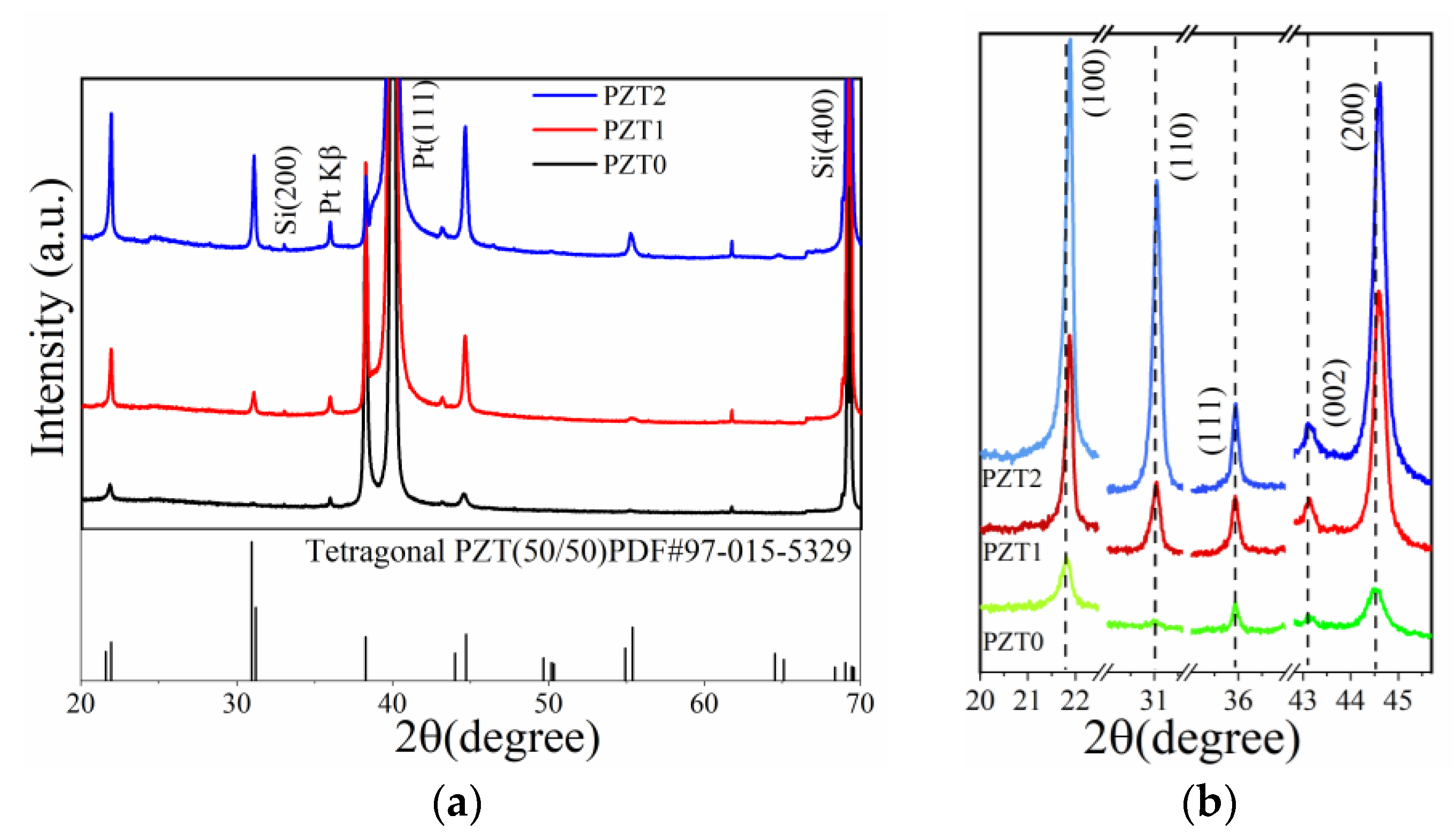
As shown in Figure 2a, the X-ray diffraction (XRD) patterns of the as-prepared thick films exhibit a single perovskite phase without any second phase detected. All the diffraction peaks in the XRD patterns correspond well with that of the PDF card # 97-015-5329, which reveals a tetragonal PZT microstructure for all the prepared thick films. Figure 2b clearly shows that the diffraction peaks of PZT1 and PZT2 thick films shift towards higher angles, which indicates a decrease in lattice parameters of the prepared PZT thick films due to the introduction of the BSZT buffer layer. It is agreed that the lattice constant of PZT is larger than that of BSZT due to the larger ion radius of Pb2+. As a result, the lattice size of PZT grown on BSZT is relatively smaller [27]. The full width at half maximum (FWHM) of the diffraction peaks from the data of all the thick films in Figure 2a are provided in Table 1. The results demonstrate that the PZT thick films with the BSZT buffer layer show better crystallinity. No BSZT buffer layer information was detected in the XRD results for both PZT1 and PZT2 thick films. A high-power technology, Grazing-Incidence Wide-Angle X-ray Scattering (GIWAXS), was employed to check the as-prepared thick films. The results shown in Figure 3 provide evidence of a BSZT layer in both PZT1 and PZT2 thick films.
The I-q(Å−1) curves of PZT0, PZT1, and PZT2 thick films with different incident angles, obtained using GIWAXS technology, are shown in Figure 3. Figure 3a shows the I-q(Å−1) curves of PZT0, PZT1, and PZT2 thick films with incident angles of 1.0°. All the samples show the same diffraction peaks of PZT (001), (110), (111), and (002), which are consistent with the results in Figure 2a. With the increasing incident angle values, BSZT (001) diffraction peaks could be observed in PZT1 (Figure 3c) and PZT2 (Figure 3d) thick films. The results suggest that the diffraction signals of BSZT buffer layers are too weak to be detected by XRD technology, since the BSZT layers were very thin and covered by a much thicker PZT thick film in our case.
Figure 4 shows the back-scattered electron (BSE) imaging micrographs of the thick films’ cross-sectional structure. The thicknesses of the PZT thick films were 1.394 μm, 1.389 μm, and 1.373 μm for the PZT0, PZT1, and PZT2 samples, respectively. As shown in Figure 4, the prepared films are relatively dense and contain tiny pores, which are caused by the volatilization of Pb during the heat treatment process. The Energy-Dispersive Spectrometer (EDS) results of the thick films show that the chemical composition of all the thick films tested should be PbZr0.50Ti0.50O3.
Figure 5a illustrates the dielectric constant and dielectric loss, which are dependent on the testing frequency of the prepared thick films after aging for 96 hrs. The PZT thick films with the BSZT buffer layer show higher dielectric constant values, εr~880 for the PZT1 thick film and εr~698 for the PZT2 thick film at 1 MHz, respectively, while the εr of the PZT0 thick film was around 457 at 1 MHz. The dielectric losses of all prepared thick films are less than 4% at 1 MHz, as shown in Figure 5b. This suggests that the enhancement of the dielectric response of the thick films may be attributed to the BSZT buffer layer. Compared with the PZT2 thick film, the higher εr value of the PZT1 thick film could be attributed to its better crystallinity.
The εr of the as-prepared thick films versus the strength of the AC electric field at different frequencies (10 kHz to 1 MHz) is shown in Figure 6a–c. The εr values changed slightly when the AC electric field strength is smaller than 5 kV/cm for all the thick films. When the applied electric field strength increased to higher than 5 kV/cm, the dielectric constants of all thick films linearly increased with the increase in electric field strength in our test ranges. In this linear increase region, the dielectric response behaviors could be characterized by Rayleigh’s law [1]:
εr (E0) = εr (0) + αE0
where E0 is the amplitude of the electric field oscillation, εr (0) is the reversible Rayleigh coefficient or initial dielectric constant originating from the intrinsic lattice dielectric response, and α is the irreversible Rayleigh coefficient describing the extrinsic dielectric response due to the irreversible motion of the domain wall or phase boundaries [28,29].
Figure 6d and Figure 6e show the profiles of εr (0) and α, respectively, at different testing frequencies. εr (0) shows mild changes with the increase in frequency for all thick films and α shows a significant decrease with the increase in frequency for all thick films. It is reasonable that the irreversible motion of the domain wall or phase boundaries becomes difficult with the increase in testing frequency. It was noted that the PZT1 and PZT2 thick films both showed higher values of εr (0) and α than that of the PZT0 thick film, which suggests that the BSZT buffer layers enhance both the intrinsic (reversible) dielectric response and extrinsic (irreversible) dielectric response of thick films.
Figure 7a shows the P-E loops of the as-prepared thick films tested at about 1000 kV/cm. The results indicate that thick films with a BSZT buffer layer possess higher Pr and Pmax values than thick films without the BSZT buffer layer. Among them, the PZT1 thick film showed the largest remanent polarization Pr (42.4 μC/cm2) and maximum polarization Pmax (75.8 μC/cm2), as well as the smallest coercive field Ec (85 kV/cm). To subtract the non-ferroelectric switching polarization from the P-E loops of the thick films, the PUND measurements were carried out by applying a series of five pulses (one preset, and two positive ups and two negative downs). As shown in Figure 7b, the first and third pulses (P and N) were used to measure the total amount of polarization (P*), which includes the ferroelectric polarization contribution, the leakage current’s contribution due to the space charges’ polarization effect, and the dielectric contribution [30]. The second and fourth pulses (U and D) were used to measure the total amount of non-ferroelectric polarization (P^) originating from the leakage current and dielectric contribution. The ferroelectric remanent polarization (Pr*) can be obtained according to the difference (∆P) between P* and P^ polarization, as shown in the following equation [31]:
2Pr* = ∆P = P* − P^
Figure 7c shows the ±Pr* values from the PUND test depicted in Figure 7b and the ±Pr values from the P-E loops depicted in Figure 7a. The Pr*/Pr ratios of the thick films were 70.8%, 68.7%, and 63.8% for PZT1, PZT2, and PZT0, respectively. This indicates that the ferroelectric polarization of the thick film could be enhanced by the BSZT buffer layer.
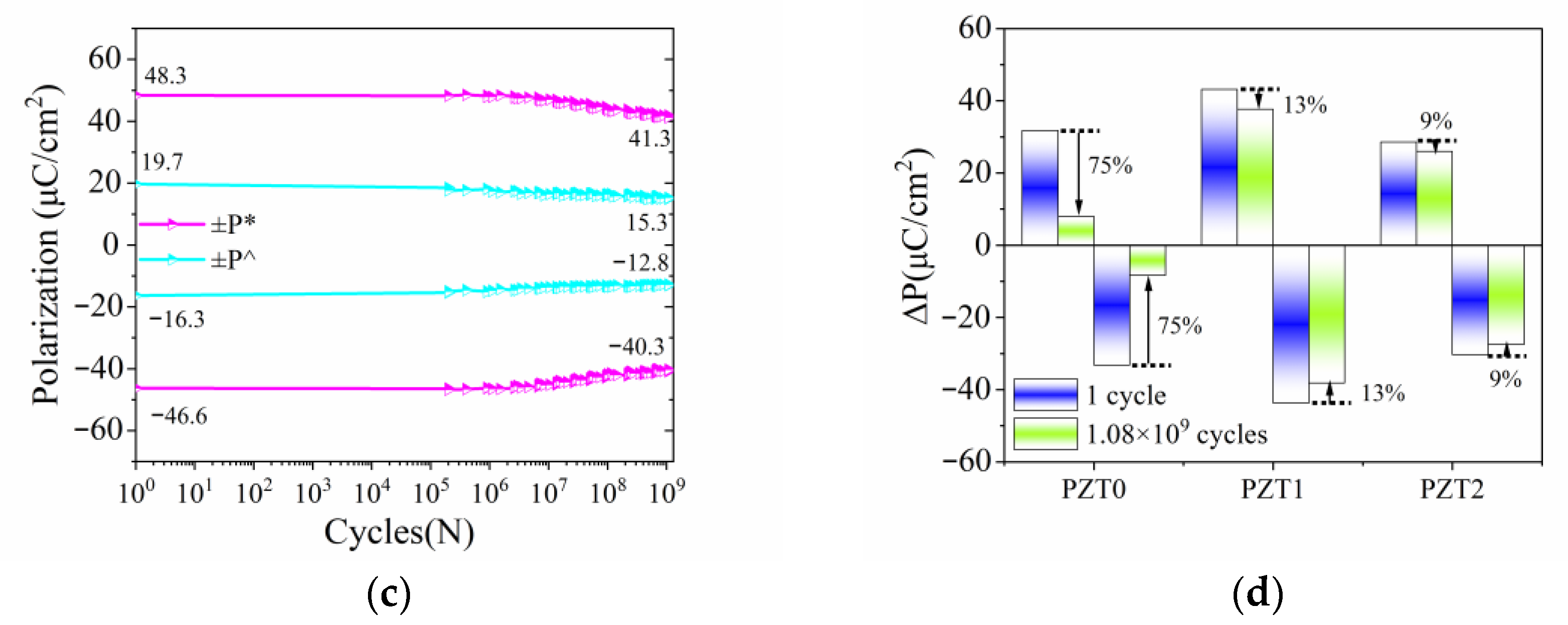
The polarization fatigue results of the as-prepared thick films are shown in Figure 8. The fatigue testing used the bipolar triangular wave signals for cycling at Emax= 367.8 kV/cm. The polarization fatigue curves could be divided into several stages according to the recording points, and the PUND testing was recorded at the end of every stage of testing in the same electric field [15].
The curves depicted in Figure 8a–c show that the ±P* and ±P^ are essentially symmetrical during fatigue cycles for all the thick films. Different from the PZT1 and PZT2 thick films, the polarization values of PZT0 thick film show a sharp decrease of 65% in P* values from 43.1 μC/cm2 to 14.9 μC/cm2 and a similar decrease of 57% in P^ from 11.3 μC/cm2 to 4.9 μC/cm2 after 4 × 10⁵ cycles (see Figure 8a). The PZT1 and PZT2 thick films show a relatively mild decrease. Even after over 1.08 × 10⁹ cycles, the P* values of the PZT1 thick film decreased by 13% and the P^ values decreased by 13% (see Figure 8b), and the P* values of the PZT2 thick film decreased by 14% and the P^ values decreased by 22% (see Figure 8c).
Figure 8d shows the ferroelectric polarization ±(P* − P^) = ±∆P of all thick films after the first cycle and after 1.08 × 10⁹ cycles. Obviously, the BSZT-buffered PZT thick films show significantly improved polarization fatigue characteristics. There was a decline of 13% in ∆P for the PZT1 thick film and of 9% for the PZT2 thick films. The PZT0 thick film showed a reduction of 75% in ∆P, which is similar to that reported in References [31,32] for the PZT/Pt film system.
The influence of polarization fatigue on the dielectric response was investigated. The AC electric field dependence of dielectric constant εr of the thick films with different fatigue cycles is shown in Figure 9a. The εr of the PZT0 thick film shows an obvious reduction after 1.08 × 10⁹ cycles compared to that of the PZT1 and PZT2 thick films.
Figure 9b,c reveal the varying extents of the decrease in Rayleigh coefficient εr (0) and α for the PZT0, PZT1, and PZT2 samples after 1.08 × 10⁹ cycles. Among them, the PZT0 thick film shows strong dielectric response decreases in εr (0) of 23% and α of 52%, which is similar to the results reported in Reference [1]. However, the decrease in εr (0) was 5% for the PZT1 thick film and 2% for the PZT2 thick film, respectively. Simultaneously, the reduction in α value was 9% for the PZT1 thick film and 5% for the PZT2 thick film. The results reveal that the BSZT buffer layer can improve dielectric fatigue in both the intrinsic (reversible) dielectric response and extrinsic (irreversible) dielectric response of the thick films.
Figure 10 shows the leakage current densities of as-prepared thick film after 1 cycle and 1.08 × 10⁹ cycles of polarization fatigue testing. The evolution of leakage current density over varying numbers of fatigue cycles is contradictory. A decrease in leakage current density with an increase in the number of cycles was reported in PZT thick films [33,34,35] and a dramatic increase in the leakage current density of PZT thick films after fatigue was also reported [36,37]. In the present work, the leakage current densities of all the thick films were smaller than 1 × 10⁻⁵ A/cm2 at 400 kV/cm after one cycle, as shown in Figure 10a; the PZT1 and PZT2 thick films showed slightly higher values than the PZT0 thick film. After 1.08 × 10⁹ cycles, the leakage current density of the PZT0 and PZT2 thick films hardly changed from the values reported in Figure 10b until the electric field strength reached 250 kV/cm. Then, the values of the PZT0 thick film increased sharply at 300 kV/cm, reaching 2 × 10⁻³ A/cm2, and the PZT2 thick film showed a stable leakage current density behavior, as shown in Figure 10b, after 1.08 × 10⁹ cycles. Different from the PZT2 thick film, there was a one-magnitude rise in leakage current density for the PZT1 thick film after 1.08 × 10⁹ cycles, which was attributed to the presence of a thinner BSZT layer than that in the PZT2 thick film. The results indicate that the leakage current density could be significantly influenced by a BSZT buffer layer with the proper thickness.

4. Conclusions

The presence of a BSZT buffer layer was shown to effectively improve the crystallinity of PZT thick films. The microstructure modification enhanced both the intrinsic (reversible) and extrinsic (irreversible) dielectric response of the PZT thick films, resulting in an increase in dielectric constant from 705 to 1063 at 10 kHz and the remanent polarization rising from 37 μC/cm2 to 42.4 μC/cm2 in the PZT1 thick film. In addition, the BSZT buffer layer shared its solid solution composition and perovskite structure with the PZT thick film, which stabilized the perovskite phase in PZT thick films. The stabilized perovskite microstructure improved the polarization fatigue of PZT thick films. There was only a 9% loss after 1.08 × 10⁹ cycles at a much higher electric field strength, 368 kV/cm. The Rayleigh coefficients, εr(0) and α, of the PZT2 thick film decreased by only 2% and 5%, respectively, after 1.08 × 10⁹ cycles. Additionally, the leakage current density hardly changed after 1.08 × 10⁹ cycles.
The above results make the BSZT buffer layer a promising solution for enhancing the durability and performance of PZT thick films. BSZT buffer layers provide a practical approach to exploit the full potential of PZT thick films and to expand their applications in piezoelectric and ferroelectric devices.

Author Contributions

Data curation, investigation, formal analysis, methodology, writing—original draft, K.W.; data curation, formal analysis, J.Z.; data curation, investigation, Z.F.; methodology, investigation, conceptualization, funding acquisition, writing—review and editing, project administration, supervision, P.Y. All authors have read and agreed to the published version of the manuscript.

Funding

This work is supported by the National Natural Science Foundation of China under grant No. u1601208, China.

Institutional Review Board Statement

Not applicable.

Informed Consent Statement

Not applicable.

Data Availability Statement

The data are available on request from the corresponding authors.

Acknowledgments

This work is supported by the National Natural Science Foundation of China under grant Nos. u1601208. A portion of this work is based on the data obtained at BSRF-1W1A. The authors gratefully acknowledge the cooperation of the beamline scientists at BSRF-1W1A beamline. The authors also appreciate the help of Wang Hui from the Analytical & Testing Center of Sichuan University with the SEM characterization and component analysis.

Conflicts of Interest

The authors declare no conflicts of interest.

References

  1. Lou, X.J.; Zhang, H.J.; Luo, Z.D.; Zhang, F.P.; Liu, Y.; Liu, Q.D.; Fang, A.P.; Dkhil, B.; Zhang, M.; Ren, X.B.; et al. Effect of polarization fatigue on the Rayleigh coefficients of ferroelectric lead zirconate titanate thin films: Experimental evidence and implications. Appl. Phys. Lett. 2014, 105, 102907. [Google Scholar] [CrossRef]
  2. Gerber, P.; Kügeler, C.; Ellerkmann, U.; Schorn, P.; Böttger, U.; Waser, R. Effects of ferroelectric fatigue on the piezoelectric properties (d33) of tetragonal lead zirconate titanate thin films. Appl. Phys. Lett. 2005, 86, 112908. [Google Scholar] [CrossRef]
  3. Wang, D.; Fotinich, Y.; Carman, G.P. Influence of temperature on the electromechanical and fatigue behavior of piezoelectric ceramics. J. Appl. Phys. 1998, 83, 5342–5350. [Google Scholar] [CrossRef]
  4. Zhu, H.; Chen, Y.; Chu, D.; Feng, S.; Zhang, Y.; Wang, P. Investigation of fatigue behavior of Pb (Zr0.45Ti0.55) O3 thin films under asymmetric polarization switching. Jpn. J. Appl. Phys. 2016, 55, 091501. [Google Scholar] [CrossRef]
  5. Lou, X.J. Polarization fatigue in ferroelectric thin films and related materials. J. Appl. Phys. 2009, 105, 024101. [Google Scholar] [CrossRef]
  6. Liu, Z.; Zhong, H.; Xie, D.; He, M.; Wang, C.; Lyu, H.; Yang, G.; Jin, K.; Ge, C. Reversible fatigue-rejuvenation procedure and its mechanism in Hf0.5Zr0.5O2 epitaxial films. J. Phys. Condens. Matter. 2023, 35, 204002. [Google Scholar] [CrossRef]
  7. Zhu, G.; Zeng, Z.; Zhang, L.; Yan, X. Polarization fatigue in ferroelectric vinylidene fluoride and trifluoroethylene copolymer films. Appl. Phys. Lett. 2006, 89, 102905. [Google Scholar] [CrossRef]
  8. Sidorkin, A.S.; Saint-Gregoire, P.; Nesterenko, L.P. Fatigue phenomena in thin ferroelectric films stimulated by repeated switching of the polarization. J. Adv. Dielectr. 2013, 3, 1350002. [Google Scholar] [CrossRef]
  9. Liu, G.; Zhang, Q.; Huang, H.H.; Munroe, P.; Nagarajan, V.; Simons, H.; Hong, Z.; Chen, L.Q. Reversible polarization rotation in epitaxial ferroelectric bilayers. Adv. Mater. Interfaces 2016, 3, 1600444. [Google Scholar] [CrossRef]
  10. Do, M.T.; Gauquelin, N.; Nguyen, M.D.; Wang, J.; Verbeeck, J.; Blom, F.; Koster, G.; Houwman, E.P.; Rijnders, G. Interfacial dielectric layer as an origin of polarization fatigue in ferroelectric capacitors. Sci. Rep. 2020, 10, 7310. [Google Scholar] [CrossRef]
  11. Meng, X.; Song, J.; Wang, D.; Ma, H.; Liu, B.; Wang, Y. Impacts of light on switching properties of epitaxial (Pb0.9La0.1)(Zi0.4Ti0.6)O3 capacitor with Al2O3 doped ZnO top electrode. Optik 2021, 242, 167118. [Google Scholar] [CrossRef]
  12. Scott, J.F.; Dawber, M. Oxygen-vacancy ordering as a fatigue mechanism in perovskite ferroelectrics. Appl. Phys. Lett. 2000, 76, 3801. [Google Scholar] [CrossRef]
  13. Chang, L.W.; Alexe, M.; Scott, J.F.; Gregg, J.M. Settling the” dead layer” debate in nanoscale capacitors. Adv. Mater. 2009, 21, 4911. [Google Scholar] [CrossRef]
  14. Golonka, L.J.; Buczek, M.; Hrovat, M.; Belavič, D.; Dziedzic, A.; Roguszczak, H.; Zawada, T. Properties of PZT thick films made on LTCC. Microelectron. Int. 2005, 22, 13–16. [Google Scholar] [CrossRef]
  15. Tagantsev, A.K.; Stolichnov, I.; Colla, E.L.; Setter, N. Polarization fatigue in ferroelectric films: Basic experimental findings, phenomenological scenarios, and microscopic features. J. Appl. Phys. 2001, 90, 1387–1402. [Google Scholar] [CrossRef]
  16. Lou, X.J.; Wang, J. Bipolar and unipolar electrical fatigue in ferroelectric lead zirconate titanate thin films: An experimental comparison study. J. Appl. Phys. 2010, 108, 034104. [Google Scholar] [CrossRef]
  17. Du, X.; Chen, I.W. Fatigue of Pb(Zr0.53Ti0.47)O3 ferroelectric thin films. J. Appl. Phys. 1998, 83, 7789–7798. [Google Scholar] [CrossRef]
  18. Bao, D.; Wakiya, N.; Shinozaki, K.; Mizutani, N. Ferroelectric properties of sandwich structured (Bi, La)4T3O12/Pb(Zr, Ti)O3/(Bi, La)4Ti3O12 thin films on Pt/Ti/SiO2/Si substrates. J. Phys. D Appl. Phys. 2002, 35, L1–L5. [Google Scholar] [CrossRef]
  19. Wu, Z.; Zhou, J.; Chen, W.; Shen, J.; Hu, L.; Lv, C. Effects of Ba(Mg1/3Ta2/3)O3 buffer layer on the fatigue behavior in Pb (Zr0.52Ti0.48)O3 thin films. J. Sol-Gel Sci. Technol. 2015, 74, 234–239. [Google Scholar] [CrossRef]
  20. Mensur Alkoy, E.; Uchiyama, K.; Shiosaki, T.; Alkoy, S. Improving fatigue resistance of Pb (Zr, Ti) O3 thin films by using PbZrO3 buffer layers. J. Appl. Phys. 2006, 99, 106106. [Google Scholar] [CrossRef]
  21. Lou, X.J.; Zhang, M.; Redfern, S.A.T.; Scott, J.F. Fatigue as a local phase decomposition: A switching-induced charge-injection model. Phys. Rev. B 2007, 75, 224104. [Google Scholar] [CrossRef]
  22. Lou, X.J.; Zhang, M.; Redfern, S.A.T.; Scott, J.F. Local phase decomposition as a cause of polarization fatigue in ferroelectric thin films. Phys. Rev. Lett. 2006, 97, 177601. [Google Scholar] [CrossRef] [PubMed]
  23. Fan, Y.; Yu, S.; Sun, R.; Li, L.; Yin, Y.; Du, R. Microstructure and electrical properties of Ba0.7Sr0.3(Ti1−xZrx)O3 thin films prepared on copper foils with sol–gel method. Thin Solid. Film. 2010, 518, 3610–3664. [Google Scholar] [CrossRef]
  24. Jiang, L.L.; Tang, X.G.; Jiang, Y.P.; Liu, Q.X.; Ma, C.B.; Chan, H.L.W. Epitaxial growth and dielectric properties of BSZT thin films on SrTiO3: Nb single crystal substrate prepared by pulsed laser deposition. Surf. Coat. Technol. 2013, 229, 162–164. [Google Scholar] [CrossRef]
  25. Chan, N.Y.; Wang, D.Y.; Wang, Y.; Dai, J.Y.; Chan, H.L.W. The structural and in-plane dielectric/ferroelectric properties of the epitaxial (Ba, Sr)(Zr, Ti)O3 thin films. J. Appl. Phys. 2014, 115, 234102. [Google Scholar] [CrossRef]
  26. Chen, X.; Mo, T.; Huang, B.; Liu, Y.; Yu, P. Capacitance properties in Ba0.3Sr0.7Zr0.18Ti0.82O3 thin films on silicon substrate for thin film capacitor applications. Crystals 2020, 10, 318. [Google Scholar] [CrossRef]
  27. Chen, X.; Liu, Y.; Huang, B.; Yu, P. High energy storage efficiency and temperature stability realized in the Ba0.3Sr0.7Zr0.18Ti0.82O3/LaNiO3 heterostructure thin films directly deposited on the conductive Si substrate. Appl. Phys. Lett. 2022, 121, 122901. [Google Scholar] [CrossRef]
  28. Yang, C.; Yao, Q.; Guo, H.; Geng, F.; Lv, P.; Feng, C. Abnormal dielectric behavior induced by defect dipoles in aged Na0.5Bi0.5(Ti, Zr)O3 thin film. Mater. Lett. 2016, 164, 380–383. [Google Scholar] [CrossRef]
  29. Gharb, N.B.; Trolier-McKinstry, S. Dielectric nonlinearity of Pb (Yb1∕2Nb1/2) O3–PbTiO3 thin films with {100} and {111} crystallographic orientation. J. Appl. Phys. 2005, 97, 064106. [Google Scholar] [CrossRef]
  30. Mahmoud, A.E.R.; Parashar, S.K.S. Effect of domain switching contribution on polarization current, leakage current and switching charge density studied by PUND method in (Ba1−x, Cax)TiO3 ceramics. Mat. Sci. Eng. B 2019, 246, 13–20. [Google Scholar] [CrossRef]
  31. Shimura, R.; Tue, P.T.; Tagashira, Y.; Shimoda, T.; Takamura, Y. Solution-based process with thermal UV treatment for fabrication of piezoelectric PZT films for an actuator array at temperatures under 450 °C. Sens. Actuat. A-Phys. 2017, 267, 287–292. [Google Scholar] [CrossRef]
  32. Wang, J.; Nguyen, M.D.; Gauquelin, N.; Verbeeck, J.; Do, M.T.; Koster, G.; Rijnders, G.; Houwman, E. On the importance of the work function and electron carrier density of oxide electrodes for the functional properties of ferroelectric capacitors. Phys. Status Solidi-R. 2020, 14, 1900520. [Google Scholar] [CrossRef]
  33. Mihara, T.; Watanabe, H.; de Araujo, H.W.P. Characteristic change due to polarization fatigue of sol-gel ferroelectric Pb(Zr0.4Ti0.6)O3 thin-film capacitors. Jpn. J. Appl. Phys. 1994, 33, 5281. [Google Scholar] [CrossRef]
  34. Colla, E.L.; Kholkin, A.L.; Taylor, D.; Tagantsev, A.K.; Brooks, K.G.; Setter, N. Characterisation of the fatigued state of ferroelectric PZT thin-film capacitors. Microelectron. Eng. 1995, 29, 145–148. [Google Scholar] [CrossRef]
  35. Stolichnov, I.; Tagantsev, A.; Setter, N.; Okhonin, S.; Fazan, P.; Cross, J.S.; Tsukada, M. Dielectric breakdown in (Pb, La)(Zr, Ti)O3 ferroelectric thin films with Pt and oxide electrodes. J. Appl. Phys. 2000, 87, 1925–1931. [Google Scholar] [CrossRef]
  36. Scott, J.F.; Araujo, C.A.; Melnick, B.M.; McMillan, L.D.; Zuleeg, R. Quantitative measurement of space-charge effects in lead zirconate-titanate memories. J. Appl. Phys. 1991, 70, 382–388. [Google Scholar] [CrossRef]
  37. Wang, J.L.; Lai, Y.S.; Chiou, B.S.; Tseng, H.Y.; Tsai, C.C.; Juan, C.P.; Jan, C.K.; Cheng, H.C. Study on fatigue and breakdown properties of Pt/(Pb,Sr)TiO3/Pt capacitors. J. Phys. Condens. Matter. 2006, 18, 10457. [Google Scholar] [CrossRef]
Figure 1. Schematic and test diagram of PZT0 (a), PZT1 (b), and PZT2 (c) samples.
Coatings 15 00568 g001
Figure 2. (a) The XRD pattens of PZT0, PZT1, and PZT2 samples; (b) the XRD pattens of the main peak in PZT thick films.
Coatings 15 00568 g002
Figure 3. The GIWAXS I-q(Å−1) curves of PZT0, PZT1, and PZT2 thick films with different incident angles. (a) I-q(Å−1) curves of PZT0, PZT1, and PZT2 thick films with incident angles of 1.0°; (b) I-q(Å−1) curves of PZT0 thick film with different incident angles; (c) I-q(Å−1) curves of PZT1 thick film with different incident angles; (d) I-q(Å−1) curves of PZT2 thick film with different incident angles.
Coatings 15 00568 g003
Figure 4. The BSE micrographs of the cross-section microstructure of PZT0 (a), PZT1 (b), and PZT2 (c) thick films.
Coatings 15 00568 g004
Figure 5. The dielectric properties of PZT thick films. (a) The dependence of the dielectric constant and dielectric loss on frequency; (b) comparison of the dielectric constant and dielectric loss of the PZT thick films at 1 MHz.
Coatings 15 00568 g005
Figure 6. The dielectric constant dependent oscillating field measured at 10, 100, 400, 800 kHz and 1 MHz of PZT0 (a), PZT1 (b), and PZT2 (c); the frequency dependence of εr (0) (d) and α (e).
Coatings 15 00568 g006aCoatings 15 00568 g006b
Figure 7. The PZT thick films P-E testing results (a) and PUND test (b); Pr comparison (c).
Coatings 15 00568 g007
Figure 8. Fatigue of films in the PZT0 sample (a), PZT1 sample (b), and PZT2 sample (c). (d) ∆P comparison of PZT thick films.
Coatings 15 00568 g008aCoatings 15 00568 g008b
Figure 9. The εr-dependent oscillating field (a) and the variations in reversible Rayleigh coefficients (b) and irreversible Rayleigh coefficients (c) after 1 cycle and 1.08 × 10⁹ cycles at 100 kHz.
Coatings 15 00568 g009
Figure 10. Leakage current density versus the electric field of PZT thick films after 1 cycle (a) and after 1.08 × 10⁹ cycles (b).
Coatings 15 00568 g010
Table 1. The FWHM of PZT0, PZT1, and PZT2 samples from XRD data.
Sample FWHM(100) (°)FWHM(110) (°)FWHM(111) (°)FWHM(200) (°)
PZT00.242\0.2510.387
PZT10.1580.1930.1610.253
PZT20.1860.1960.1680.275
Disclaimer/Publisher’s Note: The statements, opinions and data contained in all publications are solely those of the individual author(s) and contributor(s) and not of MDPI and/or the editor(s). MDPI and/or the editor(s) disclaim responsibility for any injury to people or property resulting from any ideas, methods, instructions or products referred to in the content.