
Fabrication and Mechanism Investigation of High-Porosity Micro-Arc Oxidation Functional Coating on Aluminum Foam Substrate

Abstract
1. Introduction
2. Experimental
3. Results and Discussion
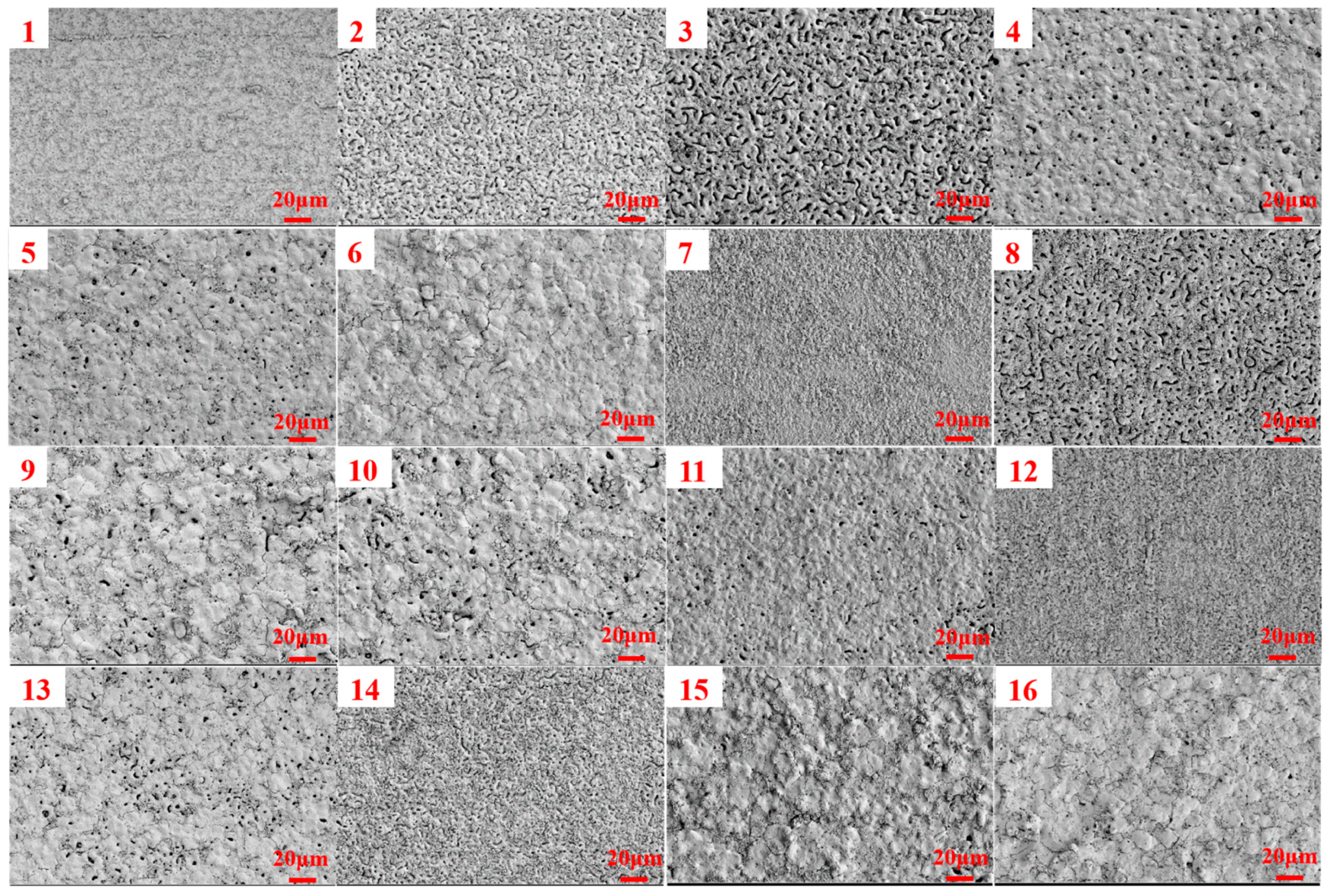
3.1. Orthogonal Experimental Analysis
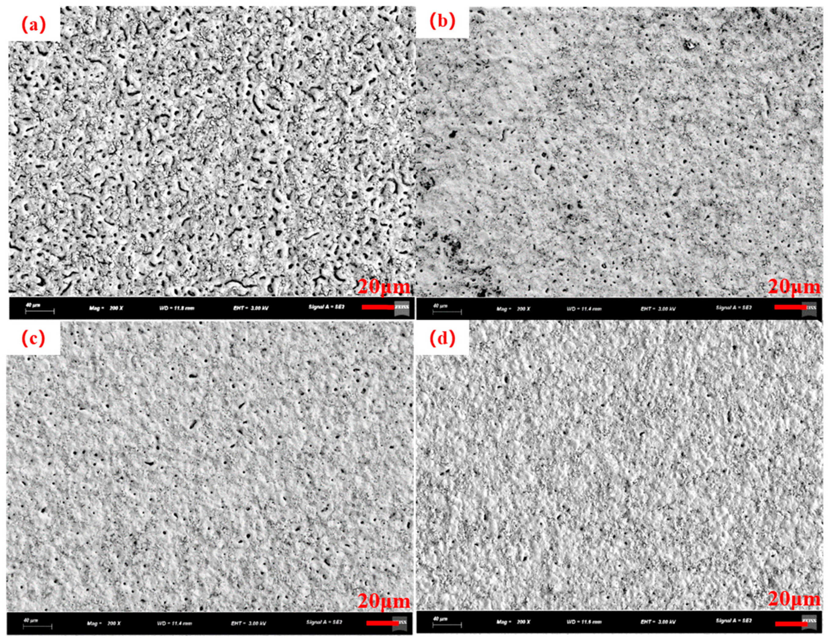
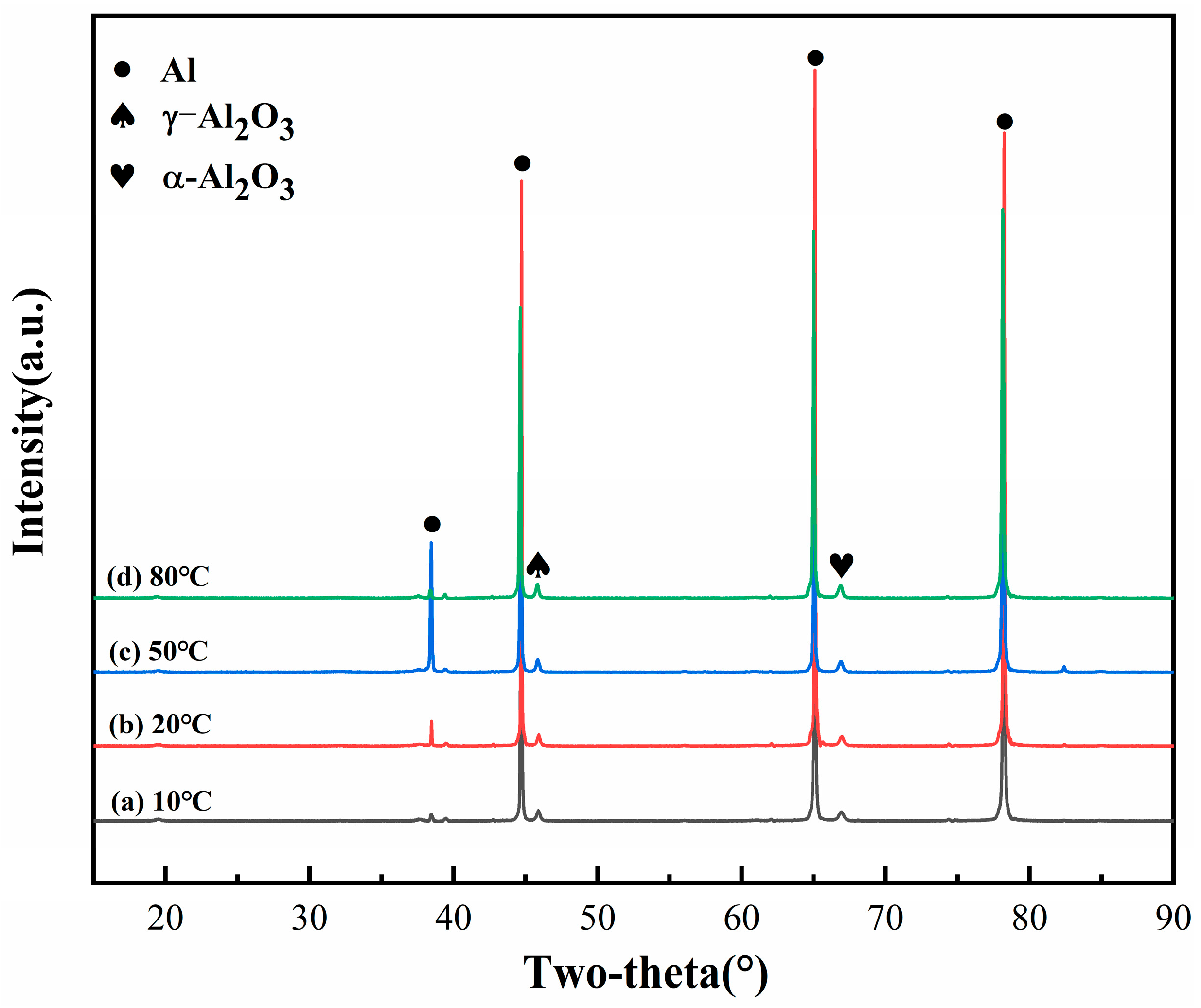
3.2. Electrolyte Temperature Control
3.3. Introduction of Pore-Forming Agents
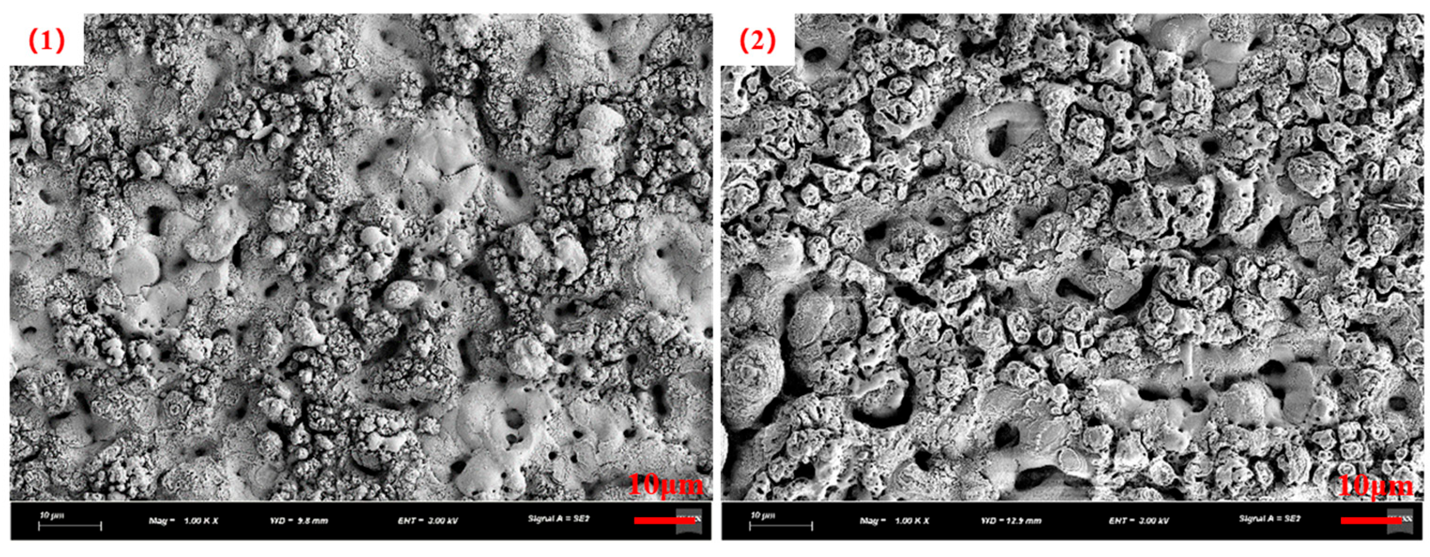
3.4. Catalyst Immobilization via Micro-Arc Oxidation
4. Conclusions
Author Contributions
Funding
Institutional Review Board Statement
Informed Consent Statement
Data Availability Statement
Conflicts of Interest
References
- Furukawa, H.; Cordova, K.E.; O’Keeffe, M.; Yaghi, O.M. The chemistry and applications of metal-organic frameworks. Science 2013, 341, 974. [Google Scholar] [CrossRef] [PubMed]
- Karakas, G.; Yetisemiyen, P. Room Temperature Photocatalytic Oxidation of Carbon Monoxide Over Pd/TiO2–SiO2 Catalysts. Top. Catal. 2013, 56, 1883–1891. [Google Scholar] [CrossRef]
- Li, M.; He, Z.; Zhong, H.; Hu, L.; Sun, W. Oxygen vacancy enhances the catalytic activity of trimetallic oxide catalysts for efficient peroxymonosulfate activation. Environ. Sci. Nano 2022, 3, 1037–1051. [Google Scholar] [CrossRef]
- Jeong, M.H.; Sun, J.; Han, G.Y.; Lee, D.H.; Bae, J.W. Successive reduction-oxidation activity of FeOx/TiO2 for dehydrogenation of ethane and subsequent CO2 activation. Appl. Catal. B Environ. 2020, 270, 118887. [Google Scholar] [CrossRef]
- Parlett, C.M.A.; Wilson, K.; Lee, A.F. Hierarchical porous materials: Catalytic applications. Chem. Soc. Rev. 2013, 42, 3876–3893. [Google Scholar] [CrossRef]
- Lee, S.-Y.; Park, S.-J. TiO2 photocatalyst for water treatment applications. J. Ind. Eng. Chem. 2013, 19, 1761–1769. [Google Scholar] [CrossRef]
- Banhart, J.; Seeliger, H. Recent Trends in Aluminum Foam Sandwich Technology. Adv. Eng. Mater. 2012, 14, 1082–1087. [Google Scholar] [CrossRef]
- Madgule, M.; Sreenivasa, C.G.; Borgaonkar, A.V. Aluminium metal foam production methods, properties and applications—A review. Mater. Today Proc. 2022, 77, 673–679. [Google Scholar] [CrossRef]
- Kim, K.-H.; Lee, K.-Y.; Kim, H.-J.; Cho, E.; Lee, S.-Y.; Lim, T.-H.; Yoon, S.P.; Hwang, I.C.; Jang, J.H. The effects of Nafion® ionomer content in PEMFC MEAs prepared by a catalyst-coated membrane (CCM) spraying method. Int. J. Hydrogen Energy 2010, 35, 2119–2126. [Google Scholar] [CrossRef]
- Shimura, K.; Miyazawa, T.; Hanaoka, T.; Hirata, S. Preparation of Co/Al2O3 catalyst for Fischer–Tropsch synthesis: Combination of impregnation method and homogeneous precipitation method. Appl. Catal. A Gen. 2014, 475, 1–9. [Google Scholar] [CrossRef]
- Bayati, M.; Aminzare, M.; Molaei, R.; Sadrnezhaad, S. Micro arc oxidation of nano-crystalline Ag-doped TiO2 semiconductors. Mater. Lett. 2011, 65, 840–842. [Google Scholar] [CrossRef]
- Markov, M.A.; Krasikov, A.V.; Ulin, I.V.; Gerashchenkov, D.A.; Bykova, A.D.; Yakovleva, N.V.; Shishkova, M.L.; Fedoseev, M.L. Formation of porous ceramic supports for catalysts by microarc oxidation. Russ. J. Appl. Chem. 2017, 90, 1417–1424. [Google Scholar] [CrossRef]
- Bayati, M.; Zargar, H.; Molaei, R.; Golestani-Fard, F.; Zanganeh, N.; Kajbafvala, A. MAO-synthesized Al2O3-supported V2O5 nano-porous catalysts: Growth, characterization, and photoactivity. Appl. Surf. Sci. 2010, 256, 3806–3811. [Google Scholar] [CrossRef]
- Yerokhin, A.L.; Nie, X.; Leyland, A.; Matthews, A.; Dowey, S.J. Plasma electrolysis for surface engineering. Surf. Coat. Technol. 1999, 122, 73–93. [Google Scholar] [CrossRef]
- Wang, J.; Jiang, Z.; Wang, Y.; Xia, Q.; Yao, Z. Design of a novel immobilized solid acid coating and its application in Fenton-like oxidation of phenol. Appl. Surf. Sci. 2017, 409, 358–366. [Google Scholar] [CrossRef]
- Qin, H.; Chen, L.; Yu, X.; Wu, M.; Yan, Z. Preparation and photocatalytic performance of ZnO/WO3/TiO2 composite coatings formed by plasma electrolytic oxidation. J. Mater. Sci. Mater. Electron. 2018, 29, 2060–2071. [Google Scholar] [CrossRef]
- Zhao, Y.; Sun, T.; Liao, W.; Wang, Y.; Yu, J.; Zhang, M.; Yu, Z.-Q.; Yang, B.; Gui, D.; Zhu, C.; et al. Amphiphilic Graphene Aerogel with High Oil and Water Adsorption Capacity and High Contact Area for Interface Reaction. ACS Appl. Mater. Interfaces 2019, 11, 22794–22800. [Google Scholar] [CrossRef]
- Xue, E.; Shang, J.; Liu, F. Effect of duty cycle on electrical insulation and anti-corrosion properties of micro-arc oxidation layers prepared on 20% SiC/Al composites. Mater. Lett. 2025, 138377. [Google Scholar] [CrossRef]
- Zhai, D.; Qiu, T.; Shen, J.; Feng, K. Mechanism of tetraborate and silicate ions on the growth kinetics of microarc oxidation coating on a Ti6Al4V alloy. RSC Adv. 2023, 13, 5382–5392. [Google Scholar] [CrossRef]
- Baker, B.G.; Jasieniak, M. Analysis of Alumina-Supported Catalysts by XPS. In Surface Science; Springer: Berlin/Heidelberg, Germany, 1996. [Google Scholar] [CrossRef]
- Dementjev, A.P.; Ivanova, O.P.; Vasilyev, L.A.; Naumkin, A.V.; Nemirovsky, D.M.; Shalaev, D.Y. Altered layer as sensitive initial chemical state indicator*. J. Vac. Sci. Technol. A 1994, 12, 423–427. [Google Scholar] [CrossRef]
- Sullivan, J.; Saied, S.; Bertoti, I. Effect of ion and neutral sputtering on single crystal TiO2. Vacuum 1991, 42, 1203–1208. [Google Scholar] [CrossRef]
- Lau, W.M.; Huang, L.J.; Bello, I.; Yiu, Y.M.; Lee, S.-T. Modification of surface band bending of diamond by low energy argon and carbon ion bombardment. J. Appl. Phys. 1994, 75, 3385–3391. [Google Scholar] [CrossRef]
- Jin, F.; Chu, P.K.; Tong, H.; Zhao, J. Improvement of surface porosity and properties of alumina films by incorporation of Fe micrograins in micro-arc oxidation. Appl. Surf. Sci. 2006, 253, 863–868. [Google Scholar] [CrossRef]
- Dudareva, N.Y.; Kolomeichenko, A.V.; Deev, V.B.; Sitdikov, V.M. Porosity of Oxide Ceramic Coatings Formed by Micro-Arc Oxidation on High-Silicon Aluminum Alloys. J. Surf. Investig. X-Ray Synchrotron Neutron Tech. 2022, 16, 1308–1314. [Google Scholar] [CrossRef]
- Wang, Y.; Hu, Z.; Wu, G.; Zhang, X.; Yin, Y.; Li, L.; Yao, J. Effect of laser power on the microstructure and wear resistance of TiO2-SiO2 ceramic coating by laser-assisted micro-arc oxidation on Ti6Al4V alloy. Surf. Coatings Technol. 2025, 497, 131764. [Google Scholar] [CrossRef]


| Number | Current Density (A/dm2) | Frequency (Hz) | Duty Cycle (%) | Oxidation Time(min) | Porosity (%) |
|---|---|---|---|---|---|
| 1 | 0.7 | 100 | 5 | 5 | 5 |
| 2 | 0.7 | 250 | 20 | 15 | 10 |
| 3 | 0.7 | 400 | 35 | 25 | 35 |
| 4 | 0.7 | 550 | 50 | 35 | 7 |
| 5 | 1.0 | 100 | 20 | 25 | 6 |
| 6 | 1.0 | 250 | 5 | 35 | 2 |
| 7 | 1.0 | 400 | 50 | 5 | 4 |
| 8 | 1.0 | 550 | 35 | 15 | 40 |
| 9 | 1.3 | 100 | 35 | 35 | 6 |
| 10 | 1.3 | 250 | 50 | 25 | 7 |
| 11 | 1.3 | 400 | 5 | 15 | 6 |
| 12 | 1.3 | 550 | 20 | 5 | 8 |
| 13 | 1.6 | 100 | 50 | 15 | 7 |
| 14 | 1.6 | 250 | 35 | 5 | 30 |
| 15 | 1.6 | 400 | 20 | 35 | 5 |
| 16 | 1.6 | 550 | 5 | 25 | 1 |
| K1 | 14.25 | 6 | 3.5 | 11.75 | |
| K2 | 13 | 12.25 | 7.25 | 15.75 | |
| K3 | 6.75 | 12.5 | 27.75 | 12.25 | |
| K4 | 10.75 | 14 | 6.25 | 5 | |
| R | 7.5 | 8 | 24.25 | 10.75 |
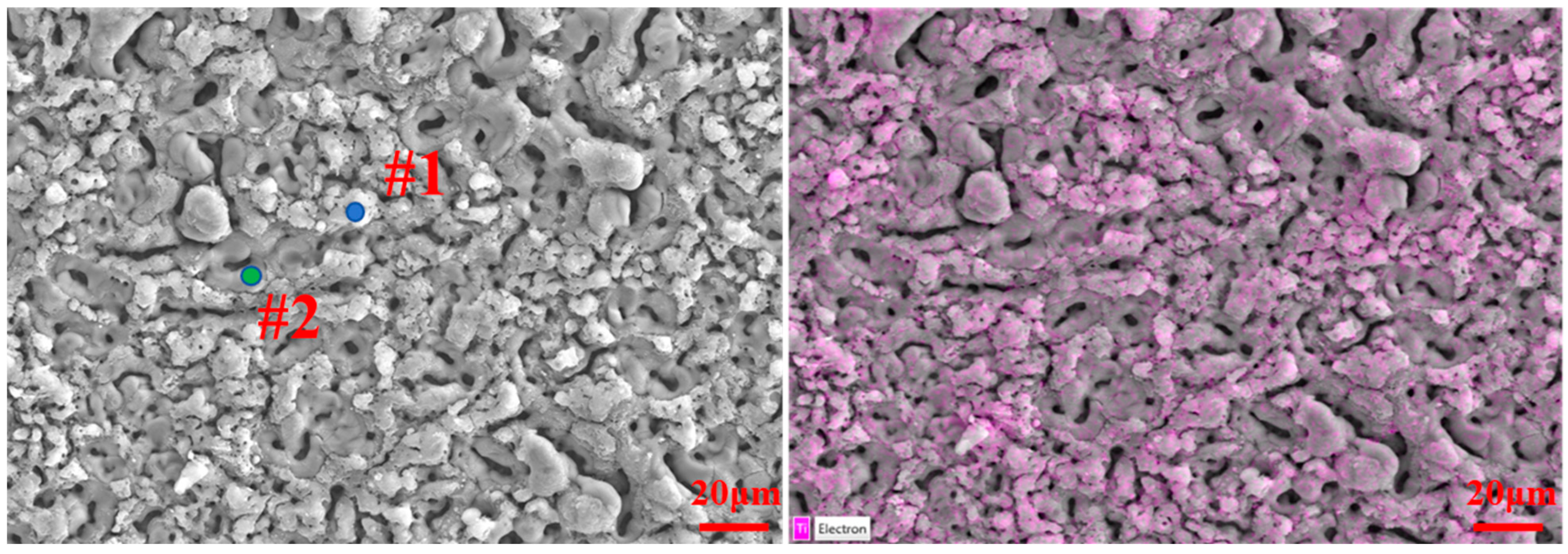
| Elements | #1 | #2 |
|---|---|---|
| Al | 20.0 | 49.7 |
| O | 63.1 | 48.6 |
| Si | 15.4 | 0.7 |
| Ti | 1.5 | 1.0 |
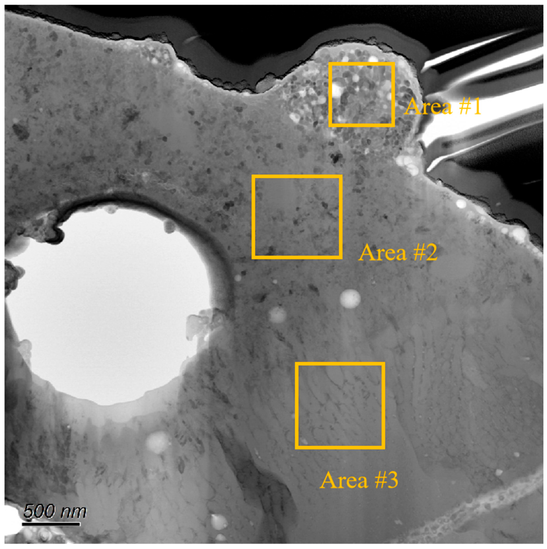
| Elements | Area#1 | Area#2 | Area#3 |
|---|---|---|---|
| Al | 0.5 | 27.8 | 38.0 |
| O | 61.7 | 58.9 | 58.0 |
| Si | 7.0 | 2.9 | 0.3 |
| Ti | 30.8 | 10.4 | 3.7 |
Disclaimer/Publisher’s Note: The statements, opinions and data contained in all publications are solely those of the individual author(s) and contributor(s) and not of MDPI and/or the editor(s). MDPI and/or the editor(s) disclaim responsibility for any injury to people or property resulting from any ideas, methods, instructions or products referred to in the content. |
© 2025 by the authors. Licensee MDPI, Basel, Switzerland. This article is an open access article distributed under the terms and conditions of the Creative Commons Attribution (CC BY) license (https://creativecommons.org/licenses/by/4.0/).
Share and Cite
Chen, X.; Li, T.; Zhu, Y.; Tian, M.; Jia, T. Fabrication and Mechanism Investigation of High-Porosity Micro-Arc Oxidation Functional Coating on Aluminum Foam Substrate. Coatings 2025, 15, 569. https://doi.org/10.3390/coatings15050569
Chen X, Li T, Zhu Y, Tian M, Jia T. Fabrication and Mechanism Investigation of High-Porosity Micro-Arc Oxidation Functional Coating on Aluminum Foam Substrate. Coatings. 2025; 15(5):569. https://doi.org/10.3390/coatings15050569
Chicago/Turabian StyleChen, Xianyin, Tao Li, Yu Zhu, Mengzhen Tian, and Tiantian Jia. 2025. "Fabrication and Mechanism Investigation of High-Porosity Micro-Arc Oxidation Functional Coating on Aluminum Foam Substrate" Coatings 15, no. 5: 569. https://doi.org/10.3390/coatings15050569
APA StyleChen, X., Li, T., Zhu, Y., Tian, M., & Jia, T. (2025). Fabrication and Mechanism Investigation of High-Porosity Micro-Arc Oxidation Functional Coating on Aluminum Foam Substrate. Coatings, 15(5), 569. https://doi.org/10.3390/coatings15050569