1. Introduction
Research on optical monitoring techniques is indispensable in the development of modern optoelectronics [
1,
2,
3]. Currently, several commercial companies and research institutions worldwide have developed optical monitoring strategies that match their process requirements for producing high-quality optical coatings. The majority have adopted more mature monochromatic techniques, which were developed many decades ago [
4,
5]. However, classical monochromatic monitoring no longer meets the requirements of modern diversified optical coating production, as its accuracy is limited by factors such as the level of processing technology and uncertainties in the optical constants of the film materials. Thus, turning-point optical monitoring with error self-compensation was designed in Ref. [
6], which enabled the industrial production of narrow bandpass filters.
Notably, in more complex optical coating preparation processes, such as shortwave-pass filters, longwave-pass filters, optical interference filters [
7], and bandpass filters with multiple passes [
8], monochromatic monitoring has difficulty meeting the precision requirements for production. In addition, the cost of setting up a monochromatic monitoring scheme is relatively high, and the results of algorithm control depend on the data accuracy, leading to high stability requirements for equipment in actual production. A more suitable strategy is to use broadband optical monitoring techniques that are more universal [
9,
10,
11]. However, when classical broadband monitoring methods are applied to ion beam coating equipment, the accuracy of automatic coating is not ideal. On the one hand, it is difficult to find a transmission curve that is completely consistent with the process design for each coating layer because of factors such as measurement errors in the spectrometer and unstable deposition rates. On the other hand, the breakpoint time of each coating layer is difficult to predict [
12]. The combination of these two factors ultimately results in an accumulation of transmission errors, which increase with the number of coating layers.
To solve this problem, the Optical Thin-Film Research Group of Institut Fresnel has designed and validated a broadband optical monitoring system with forward-layer optimization techniques. They introduced the square difference between the experimental transmitted spectrum and the simulated transmitted spectrum as an evaluation function to reoptimize the corresponding physical thickness [
13]. Later, the work [
14] introduced the multiparameter fitting method (including Cauchy coefficients for the refractive index and dispersion) to further enhance the ability of this method to find the optimal process that matches the measured transmission spectrum. The above methods are called sequential algorithms, in which only the thickness of the last layer needs to be optimized and the preceding layers are fixed. Another alternative method is the triangulation algorithm [
15], which uses all the recorded measurement scans to determine the thicknesses of all deposited layers. In principle, the triangulation algorithm has higher accuracy than sequential algorithms do, but it also has greater computational costs. To improve the computational efficiency of this algorithm, Ref. [
16] proposed an improved triangulation algorithm, which does not determine all thicknesses of previously deposited layers but only determines the thicknesses that are expected to improve the determination accuracy of the algorithm. Most of the aforementioned studies used the cumulative absolute error at each wavelength point as the standard for calculating the merit function. However, in some typical processes, especially those that focus on wide-band indicators, the cumulative absolute error alone is not sufficient to provide precise data for decision-making. Therefore, a shape-matching factor is introduced. For different processes, different weights are configured to achieve precise control. This is one of the motivations of this paper.
In addition to the transmission spectrum fitting method, the design of the breakpoint algorithm also affects the control accuracy of broadband optical monitoring methods in the automatic coating process. In fact, the best breakpoint should be the point at which the error between the theoretical transmission spectrum and the measured transmission spectrum is minimized. However, in the current coating process, the control system can perform stop judgment operations only when the error trend increases after the best breakpoint is missed, which may result in significant deposition errors. To address this issue, most works [
17] have utilized the optical thickness, fitted deposition rate, and fitted refractive index to calculate the deposition time for each layer, and a stable deposition rate is required for accurate results. In addition, to address the poor performance of broadband monitoring methods in thin-film coating processes, some researchers have introduced other monitoring methods to complement the broadband monitoring method for multilayer coatings. For example, a hybrid process control strategy that combines optical monitoring with quartz crystal monitoring methods was introduced in Ref. [
18]. In Ref. [
19], a broadband optical monitoring method combined with a time monitoring strategy was developed to control the layer thickness during the deposition process. However, employing various methods may complicate the control process.
Although there are many improvement strategies for fitting and breakpoint algorithms for broadband optical monitoring methods, the practical difficulties of inaccurate measurements and unstable coating rates in ion beam coating equipment hinder the large-scale application of broadband optical monitoring methods [
20]. Many studies have considered the superiority of their improvement strategies only in simulations [
21]. Even if an improved broadband optical monitoring method works perfectly for a model in simulations, it does not always work well for real experiments. Therefore, the coating performance of the improved broadband monitoring method should be tested in real experiments, which is another main motivation of this paper.
To address the above three challenges, this paper presents an optical monitoring method with an improved error compensation mechanism based on an independently developed ion beam coating machine (IBD-XPUTTER, IBDTEC, Inc., Foshan, China). The main features of this study are as follows.
A merit function combining absolute errors and the shape similarity of transmission spectra is designed, along with a constrained random search method, to perform the fitting optimization of the transmission spectrum.
A breakpoint algorithm based on parabolic error curve prediction is first designed, which avoids the problem of excessive deposition thickness error encountered in traditional broadband monitoring methods used for automatic coating processes.
Ion beam coating equipment is developed via an embedded system combined with a host computer architecture, and the proposed broadband monitoring method with an improved error compensation mechanism is experimentally validated.
The rest of this paper is organized as follows.
Section 2 introduces the hardware verification platform for the broadband monitoring method and formulates the control problem for this method.
Section 3 presents the broadband monitoring method with the improved error compensation mechanism. The experimental results are presented in
Section 4, and the conclusions are presented in
Section 5.
2. Preliminaries
2.1. Equipment and Problem Statement
The broadband optical monitoring method is a system-level industrial control approach that uses an ion beam coating machine (IBD-XPUTTER, IBDTEC, Inc.). Therefore, it is necessary to establish a complete hardware setup before developing the broadband optical monitoring method, as shown in
Figure 1.
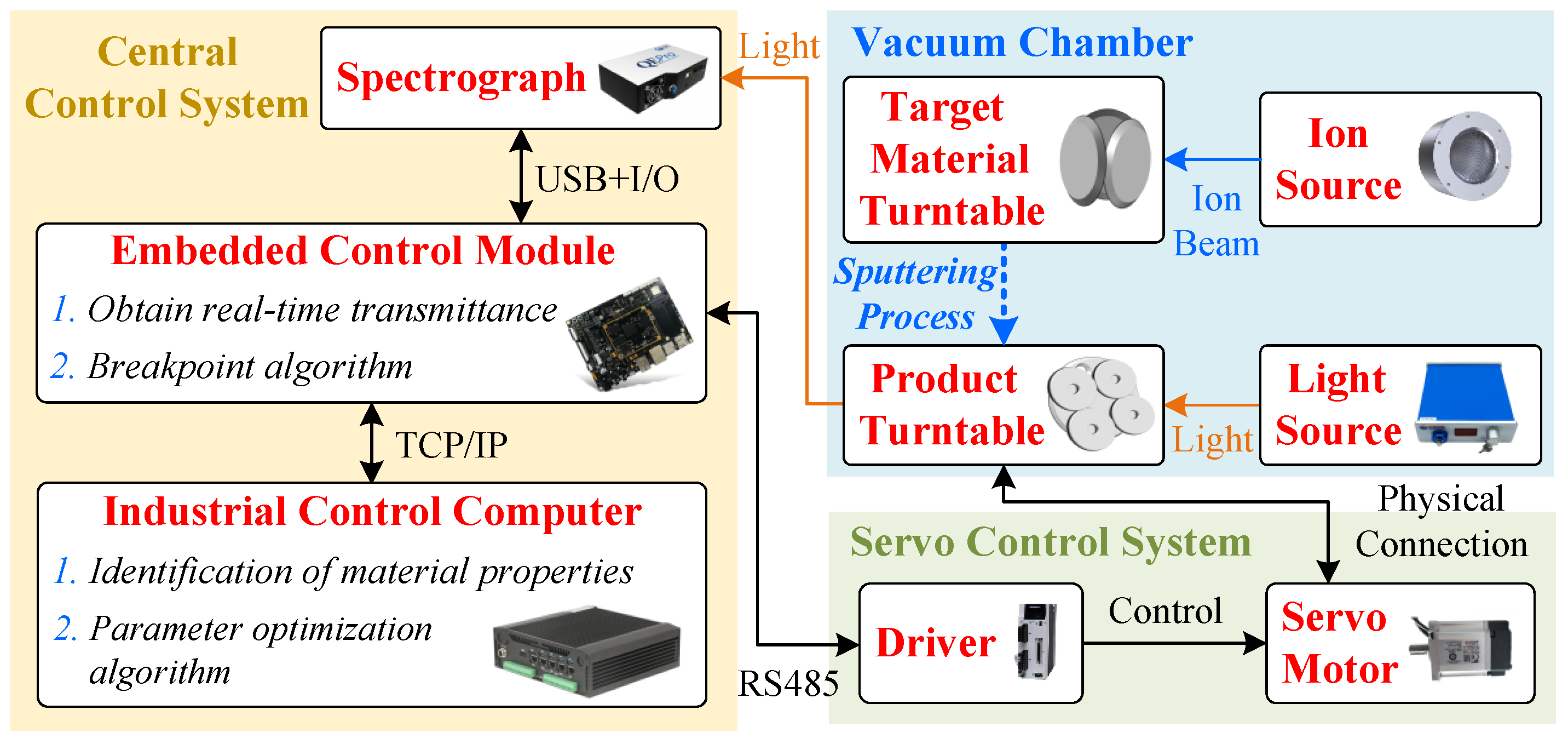
The verification platform is an ion beam coating system, with the broadband optical monitoring algorithm loaded onto the central control computer of the device. The equipment is operated as follows: first, the central control system equipped with the broadband optical monitoring algorithm sends operational instructions to each device. The product turntable is rotated using a motor, the ion source (IBD-RISE600, IBDTEC Inc.) is activated, and the target material is bombarded onto the substrate. Second, the transmitted spectrum of the product measured by the spectrometer is sent in real time to the central control system. The broadband optical monitoring algorithm compares the measured transmitted spectrum with the theoretical value. Then, at appropriate interruption nodes, the system pauses, switches the target material, and resumes ion beam bombardment. This iterative process is repeated to complete the autonomous multilayer coating process.
The broadband optical monitoring algorithm is the core of the ion beam coating machine used to complete the autonomous multilayer coating task, and a complete autonomous control strategy must be designed for this algorithm, which is also a research goal of this paper. Taking the coating process for shortwave-pass filters as an example, the problem of this paper is described as follows. The transmitted spectrum of the shortwave-pass filter is used to assess the multilayer coating performance, is chosen as the substrate material. and are chosen as the materials involved in the coating. The designed broadband optical coating algorithm can autonomously and stably direct the equipment to complete the coating process on the substrate and obtain thin film products with a transmitted spectrum close to the desired transmitted spectrum.
2.2. Identification of Material Properties
Before designing a broadband optical monitoring algorithm, it is necessary to identify the material coefficients involved in the process. Based on the transmittance results obtained from the measurement of the specified material using a spectrophotometer, the refractive index and extinction coefficient at multiple extreme points can be obtained through the Essential-Macleod version 11.9. Then, interpolation processing is carried out to obtain the refractive index and the extinction coefficient at the wavelength point .
The Cauchy absorption equation is very suitable for describing transparent materials with weak absorption; for example,
where the wavelength points are
, and
m represents the total number of sampling points of the spectrograph.
and
represent the Cauchy parameters to be identified.
Subsequently, intermediate variables are defined as
. By introducing these variables, Equation (1) is transformed into the standard Cauchy form. The parameters
,
,
,
,
, and
can then be determined using the classical least squares method [
22].
Using the above method of identifying material properties, the obtained refractive index parameter for the substrate material, , is , and the extinction coefficient parameter is . The refractive index parameter for the high-refractive-index material, , is , and the extinction coefficient parameter is . The refractive index parameter for the low-refractive-index material, SiO2, is also , with the extinction coefficient parameter .
3. Main Results
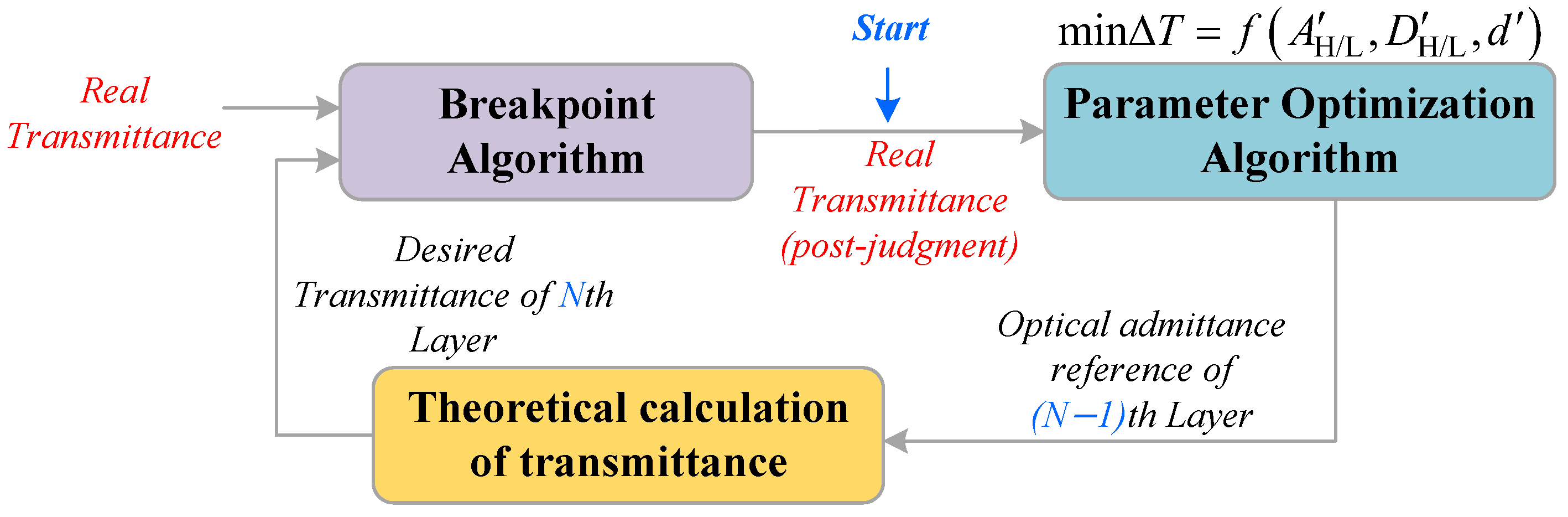
The overall logic of the broadband optical monitoring algorithm can be divided into three modules according to their functions: the breakpoint algorithm module, the theoretical calculation algorithm module, and the parameter optimization algorithm module, as shown in
Figure 2. The
Nth (
) layer coating algorithm is different from the first layer coating algorithm.
First, when the number of coating layers is one, the optimization module is not activated. Instead, the theoretical transmitted spectrum of the first layer is obtained through the theoretical calculation algorithm module on the basis of the Cauchy parameters of the target material. Second, after determining the error between the real transmitted spectrum and the theoretical transmitted spectrum, if the pause condition of the breakpoint algorithm module is met, the coating process is stopped, and the real transmitted spectrum at this time is taken as the base value of the second layer.
When the number of coating layers is N, the real transmitted spectrum at the time of pausing the th layer needs to be input into the parameter optimization algorithm module to obtain the optimized target parameters and coating thickness of the th layer. These parameters are used as the base values for calculating the theoretical transmitted spectrum of the Nth layer. Second, the real-time transmitted spectrum and theoretical transmitted spectrum are input into the breakpoint module for comparison. When the stop condition is met, the coating is stopped, and the actual transmitted spectrum at this time is taken as the base value of the th layer.
3.1. Theoretical Calculation of the Transmittance Module
The current coating layer number is the Nth layer, and the input parameters of this module include the Cauchy parameters and of the target material, the coating thickness d of this layer, and the characteristic matrix of the previous layer. The output parameters include the ideal transmitted spectrum and the characteristic matrix of this layer.
Under the assumption that the target material for this layer is
, the optical admittance at wavelength point
is
It should be noted that the substrate material
is a transparent material with almost no absorption, and its optical admittance
is suitable for description using the Sellmeier dispersion equation, such as
Considering the impact of the substrate material on the product’s transmittance, based on the transmission principle of multilayer film systems, the substrate transmittance
can be derived from its optical admittance
, such as
Then, the optical phase thickness can be obtained by
where
d indicates the optical thickness of the coating material required for this layer.
Afterward, the characteristic matrix
is calculated as
Notably, the characteristic matrix
before the coating of the first layer is a
identity matrix.
On the basis of the above results, the intermediate variables
and
can be obtained as
Finally, simultaneously considering the effects of substrate transmittance
and the coating process on the product, the multilayer film system calculation method is used to obtain the transmittance
at each wavelength point
, as
3.2. Breakpoint Algorithm Module
This module is a core component in the automated broadband coating process. As shown in
Figure 2, the module has two inputs: the real-time measured transmittance
obtained from the spectrometer, and the theoretical predicted transmittance
of the next layer, calculated by the transmittance theory module. The output of this module is the stop coating and layer replacement signal for the current layer.
For example, consider the current layer as the Nth layer. The theoretical transmittance after completing this layer has been previously calculated using the actual transmittance measured at the end of the th layer and the designed thickness of the current layer, processed through the theoretical transmittance computation module. In theory, the optimal termination point is achieved when the error between the real transmittance and the theoretical transmittance is minimized. However, the actual coating process is continuous and irreversible, making it challenging to precisely reach the theoretical minimum error point. Consequently, a breakpoint prediction algorithm is necessary to determine the appropriate stopping point.
Based on the above analysis, the transmittance error
f should first be calculated as
where
represents the weight coefficient. This is the merit function of the optimization algorithm. It should be noted that the proposed transmittance error
f incorporates a derivative error term, adjusted by a weighting coefficient
. The approach offers the advantage of capturing differences in the shape and variation trends of the spectral curve. This is particularly important for broadband coatings, as broadband spectra often exhibit features across multiple wavelength regions and relying solely on single-point error terms may overlook the overall curve matching. Increasing
enhances the weight of shape matching, while decreasing
increases the weight of absolute error. Notably, researchers have focused only on the spectral matching of certain wavelength points in this coating process, such as
.
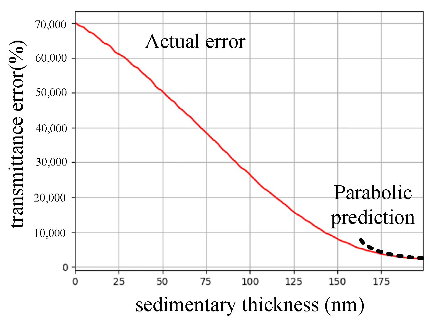
Through a large number of coating experiments, it can be seen that the error
f of a single-layer coating shows an upward parabolic shape with an opening, as shown in
Figure 3. In order to find the best stopping time, the fitting method can be used to find the quadratic equation of the parabola
, and the best breakpoint time is
. When the error
f reaches the predicted breakpoint, the module is triggered to output signals for stopping the coating process and switching layers.
Moreover, this breakpoint algorithm employs multiple averaging and Savitzky–Golay filtering methods during data acquisition to preprocess the actual data, enhancing robustness against noise and system fluctuations.
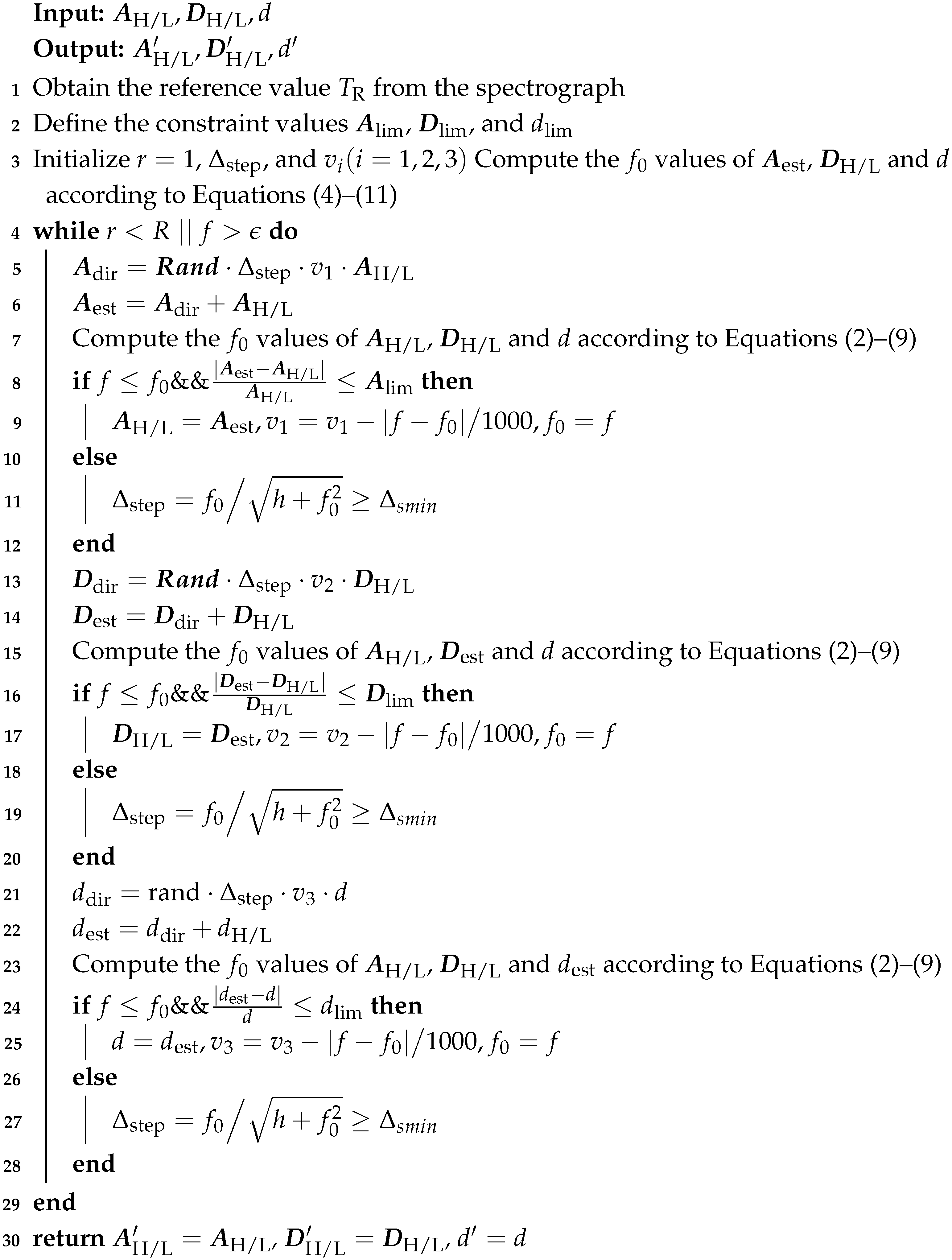
3.3. Parameter Optimization Algorithm Module
To avoid the accumulation of errors during the coating process, this module finds theoretical process parameters that are basically consistent with the actual spectral characteristics, which is the basis of the theoretically predicted transmitted spectrum of the next layer. The input parameters of this module are the Cauchy parameters , and the thickness d of the material of the th layer, as well as the real transmitted spectrum measured by the spectrophotometer of the th layer. The output parameters of this module are the optimized Cauchy parameters , and the thickness of the th layer.
The experiments described in this section involve an improved random search method with constraints. The iterative update process for the Cauchy parameter of the refractive index is taken as an example to explain the process of optimizing this value. Notably, the limit range for Cauchy parameter optimization is represented as .
First, the initialization iteration number is defined as , the total number of iterations is defined as R, and indicates the acceptable error value. By using Equation (11), the difference between the theoretical transmitted spectrum of the reference value and the actual transmitted spectrum can be obtained.
Second, the random direction of each step can be calculated as
where
represents a
diagonal matrix and
in this matrix is a random function between −1 and 1.
represents the iteration step coefficient, and
represents the rate of change in a random direction.
Next, the intermediate variable
can be updated by
On this basis, the theoretical transmittance sequence is recalculated via Equation (10) by using the refractive index parameter after the update, the extinction coefficient parameter , and the coating thickness d. Then, is subtracted from the actual transmitted spectrum to obtain the transmitted spectrum error f.
If the error satisfies and the updated value satisfies , a theoretical value closer to the real transmitted spectrum has been found. Thus, the benchmark value is updated by . To improve the optimization accuracy, the change rate is updated by and the benchmark error is updated to .
In contrast, if the error satisfies
, a better theoretical value was not found during the optimization process. To improve the success rate of optimization, the iteration step coefficient is updated by
, where
represents the acceptable minimum iteration step coefficient. The algorithmic process of this module is shown in Algorithm 1.
| Algorithm 1: Parameter optimization algorithm. |
![Coatings 15 00551 i001]() |
The procedures for choosing the main parameters of the broadband optical monitoring method are summarized as follows:
By adjusting , the absolute error of the transmitted spectrum and the weight of shape matching can be changed. The larger is, the higher the degree of shape similarity matching, and the smaller is, the smaller the absolute error.
The greater the constraints , , and are, the greater the likelihood of finding the best results , , and for that layer. However, overly relaxed constraints may mean that these optimization results deviate from the process design, making the results unreliable as a subsequent equivalent basis. Therefore, it is necessary to design , , and reasonably on the basis of experience.
The rate of the random search method can be adjusted by changing and . The initial and are generally selected to be approximately one and gradually decrease when the subsequent adaptive algorithms are applied.
To perform adaptive error compensation, we introduce the parameter optimization algorithm and the breakpoint algorithm, utilizing parabolic curve fitting for prediction in the broadband optical monitoring method. Compared with the classical monitoring method [
11], this method not only avoids the strong cumulative effects of an increasing thickness error during the automated coating process but also establishes a set of broadband optical monitoring theories that has a certain degree of portability.
4. Example
In the process scenario proposed in this paper, the refractive index and coating thickness d significantly affect the change in transmittance, whereas the extinction coefficient is small and has little effect on the change in transmittance. Therefore, the constraint values are defined as , , and . These parameter settings were obtained through extensive experimentation and engineering experience. In addition, the main parameters are chosen as , , and . The maximum number of iterations R is set as 300.
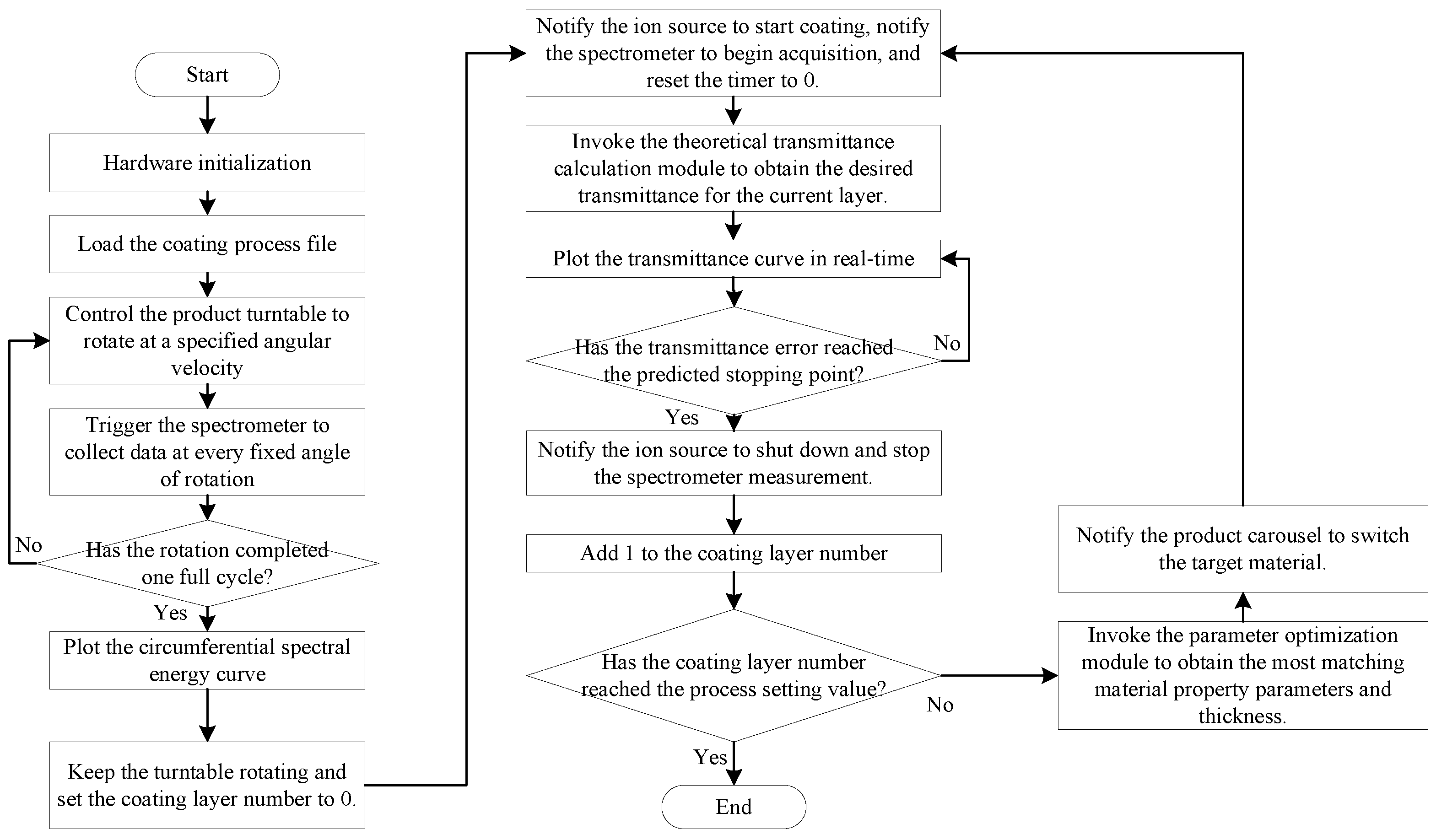
Figure 4 shows that the experimental test platform comprises a central control system, a vacuum chamber, and a servo control system. More specifically, the central control system consists of a spectrograph, an embedded control module, and an industrial control computer. A USB device is used to communicate between the spectrograph and the embedded control module. The spectrometer used is the ATP2000P (Optosky Photoics Inc., Xiamen, China), with an integration time set to 25 ms and an average acquisition frequency of 40 Hz. Notably, the embedded control module needs to implement the functions of real-time transmittance acquisition and breakpoint algorithms, both of which are implemented in the easily portable C++ language. In addition, considering that the material identification algorithm and parameter optimization algorithm require multiple iterations, both are implemented in industrial control computers with higher computational efficiency. Moreover, to facilitate the upgrading and invocation of the parameter optimization algorithm, the Python language is adopted. A network cable is used to connect the embedded control module and the industrial control computer. When the single-layer coating reaches the appropriate breakpoint, the embedded control module first sends a stop command to the servo control system, stopping the product turntable inside the vacuum chamber and shutting down the ion source. The embedded control module then sends a run command to the servo control system after the target material is switched, activating the ion source and allowing the ion beam coating process to continue. Please refer to the
Appendix A for the specific operation process based on this system.
To verify the effectiveness of the proposed broadband optical monitoring method with the improved error-compensation mechanism (named PBMM), this paper will take the preparation of a 30-layer shortwave pass filter as an example, whose theoretical transmitted spectrum is as shown in
Figure 5. Furthermore, the coating time monitoring method (named CTMM) is used as the control group to demonstrate the superiority of the proposed method in the preparation process of short-wave pass filters. It should be noted that CTMM refers to the strategy of converting the thickness of a single layer into the deposition time of that layer based on the measured deposition rate. It should be noted that legend H represents high refractive index materials, and legend L represents low refractive index materials.
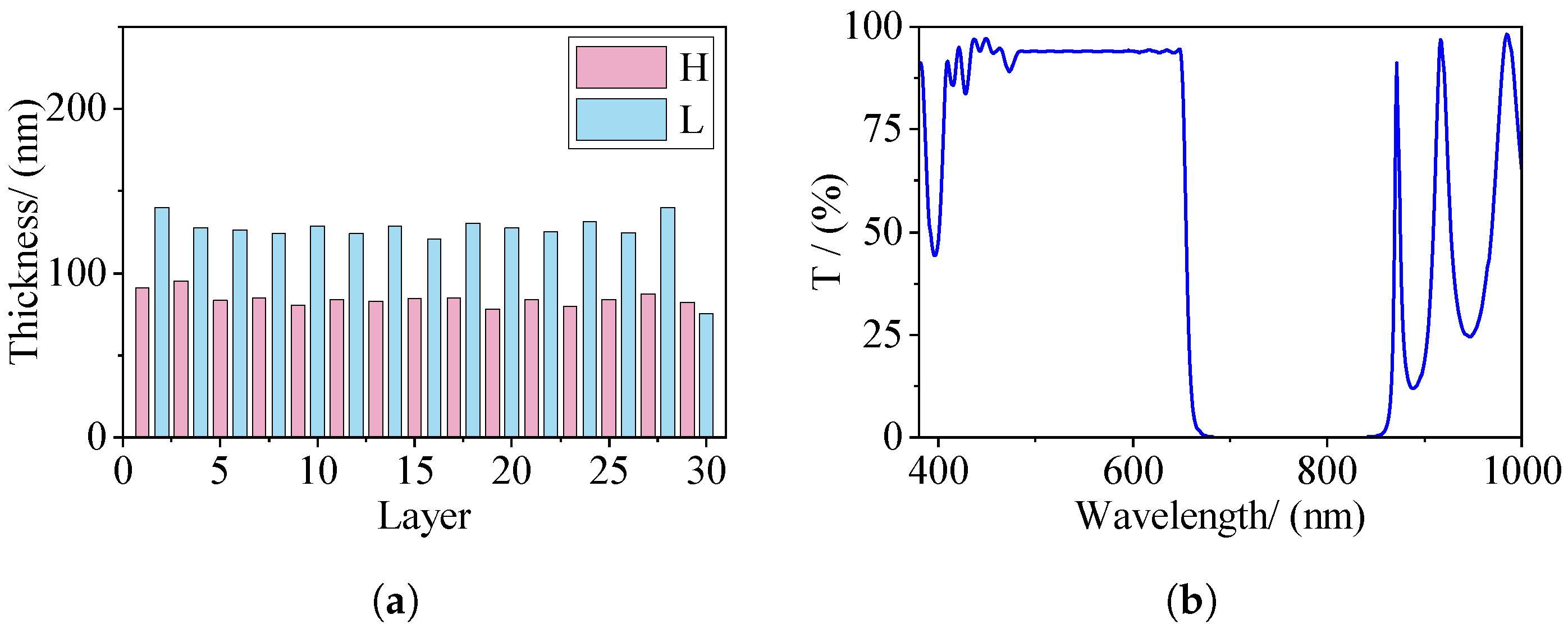
In the experiment on IBD-XPUTTER, monitoring data is transmitted spectrum data measured in the spectral region from 300 nm to 1100 nm using the wavelength step-matched with the spectrograph. In addition, the rotation period of the product turntable is set to 3.3 s. The experiment results of the coating time control method and the proposed broadband optical monitoring method are given in
Figure 6 and
Figure 7, respectively.
According to
Figure 6a,b, although the CTMM can perform the complete multilayer coating process, there is a significant deviation in the thicknesses of the layers. The reason for this is that the CTMM is an open-loop control strategy and lacks an error feedback mechanism to adaptively adjust the subsequent coating processes. As shown in
Figure 6c, the actual transmitted spectrum of the obtained filter film deviates significantly from the desired transmitted spectrum. The main reason is that there are random fluctuations in the deposition rate in the actual equipment, which leads to differences between the calculated coating time and the actual coating time, impacting the final coating effect. The pattern is more pronounced in multilayer coating processes.
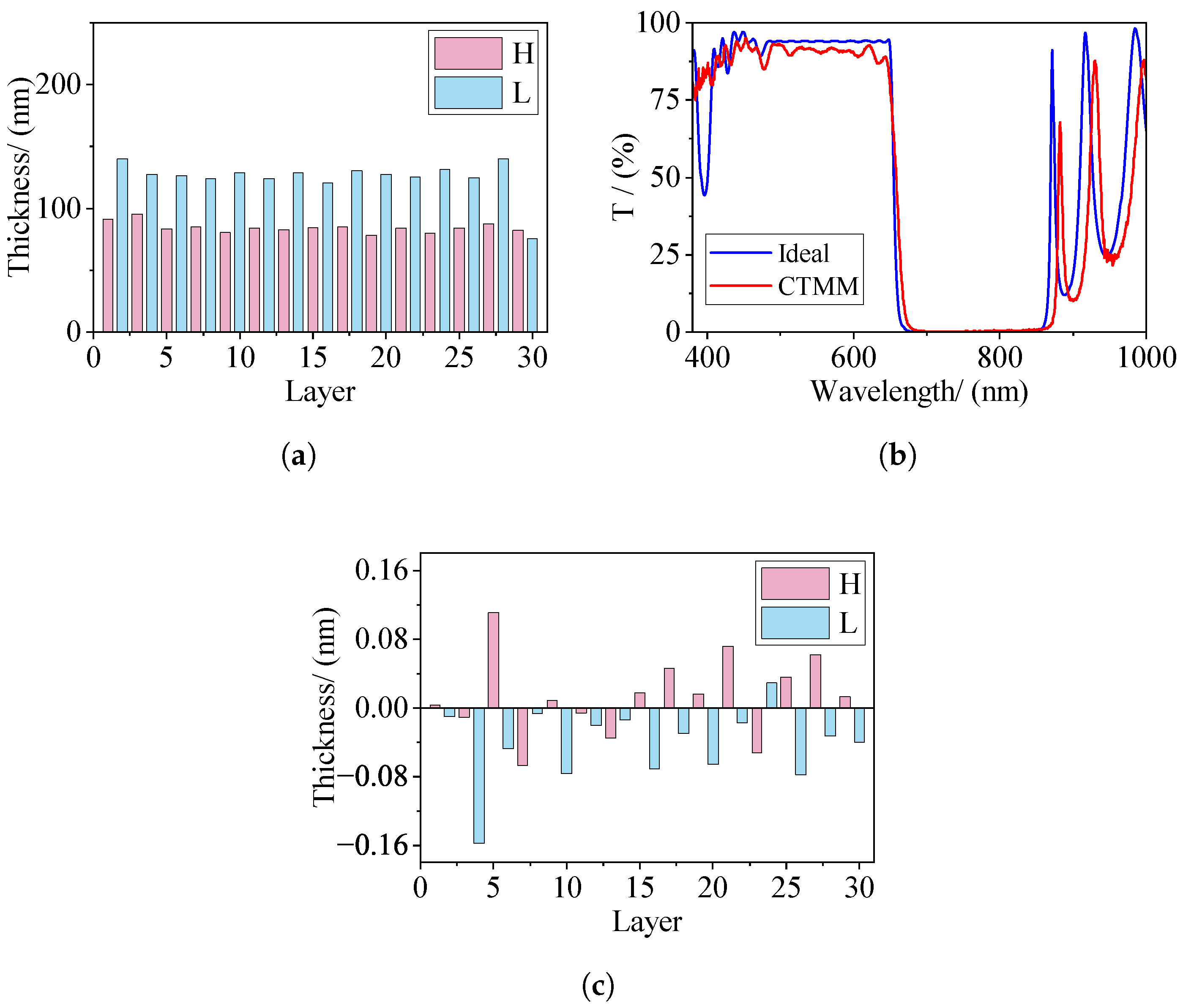
According to
Figure 7a,b, compared with the CTMM, the PBMM results in smaller film-thickness errors. The reason for this is that the improved error compensation mechanism designed for the PBMM adaptively compensates for the thickness based on the transmitted spectrum curve after each layer-deposition step.
Figure 7c clearly illustrates that the PBMM achieves a higher average transmittance in the low-pass band, and exhibits superior matching in the transmitted shortwave spectrum compared to the CTMM. Additionally, the results obtained using the PBMM are more consistent with the theoretical design.
The average value and consistency of the transmitted spectrum within the passband are also important indicators for measuring quality. Moreover, a more in-depth quantitative analysis is required to assess the performance improvements accurately. We first compared the average transmission rate within the shortwave range. The data in
Table 1 show that the average transmitted spectrum of the PBMM exceeded the process design average transmittance of 93.0498, whereas the average transmitted spectrum of the CTMM did not meet the design standards. The percentage errors of these methods with respect to the theoretical values are
and
, respectively. Regarding the average value, the PBMM improved the performance by
compared with that of the CTMM. In terms of consistency, we use the standard deviation to measure the distribution of the transmission spectrum within the passband.
Table 1 shows that the transmission rate distribution of the samples produced with the PBMM is closer to the average value, with a performance improvement of
over the CTMM. Collectively, these findings highlight the superior efficacy of the proposed PBMM method in automating the coating process for shortwave-pass filters.
Further, after conducting numerous coating experiments, we found that the optimal parameter matching can typically be achieved within 100 to 200 iterations, with the CPU parameter optimization runtime controlled within 1 s. This time interval is shorter than the sum of the product turntable’s rotation period and the single-coating duration, fulfilling the requirements for real-time coating in high-speed deposition systems.


