Article

Dual Z-Scheme MoS2/g-C3N4/Bi2O3 Composite Coating on Carbon Fiber with Enhanced Photocatalytic Performance

by
Jiantao Niu
1,2,
Jiaqi Pan
3,
Bin Zhou
1 and
Chaorong Li
1,3,*
1
College of Textile Science and Engineering, Zhejiang Sci-Tech University, Hangzhou 310018, China
2
School of Textile and Clothing and Arts and Media, Suzhou Institute of Trade and Commerce, Suzhou 215009, China
3
Department of Physics, Key Laboratory of ATMMT Ministry of Education, Zhejiang Sci-Tech University, Hangzhou 310018, China
*
Author to whom correspondence should be addressed.
Coatings 2025, 15(4), 447; https://doi.org/10.3390/coatings15040447
Submission received: 28 February 2025 / Revised: 1 April 2025 / Accepted: 8 April 2025 / Published: 10 April 2025
(This article belongs to the Special Issue Developments in Optical Coatings and Thin Films)

Abstract

:
A double-layer core–shell photocatalytic coating was engineered on carbon fibers (CFb) derived from bamboo pulp precursors, employing a sequential process involving seed pre-loading, solvothermal treatment, and impregnation. XRD, SEM, and SEM-EDS analyses revealed that g-C3N4 and Bi2O3 nanosheets were co-assembled on the carbon fiber skeleton, and 50 nm MoS2 particles were successfully loaded, resulting in the fabrication of MoS2/g-C3N4/Bi2O3/CFb photocatalytic fibers. UV–vis spectroscopy, transient photocurrent response, and EIS tests demonstrated that the introduction of narrow-bandgap visible-light photocatalysts (g-C3N4 and MoS2) enhanced light absorption and improved the separation and migration efficiency of photogenerated electron hole pairs. Photocatalytic degradation experiments of MB showed that MoS2/g-C3N4/Bi2O3/CFb significantly outperformed g-C3N4/Bi2O3/CFb and Bi2O3/CFb, achieving a degradation efficiency of 92% within 60 min. Band structure calculations and analysis confirmed the formation of Z-scheme heterojunctions between g-C3N4 and Bi2O3, as well as between MoS2 and Bi2O3. This dual Z-scheme heterojunction endowed MoS2/g-C3N4/Bi2O3/CFb with enhanced redox capabilities, providing a novel strategy for developing efficient photocatalytic materials.

1. Introduction

Wastewater generated from the production of dyes, pesticides, pharmaceuticals and their intermediates are the major sources of water pollution. Yarn or fabric dyeing is a critical process in the textile industry, which inevitably generates various types of dye wastewater. Photocatalytic technology is able to completely mineralize many organic pollutants that are difficult to biodegrade by means of semiconductor materials under the action of light, degrading them into small molecule materials such as CO2 and H2O [1].
Photocatalytic fiber refers to the photocatalyst fixed on the fiber framework by loading or embedding, which combines the properties of photocatalysts and flexible materials, such as reusability, bending and folding, and no secondary pollution after use [2]. Carbon fiber is resistant to acids, alkalis, and high temperatures, making it a high-performance material with excellent corrosion resistance and flexibility. In recent years, it has been widely used in photocatalysis due to its ability to rapidly capture surface electrons of the photocatalyst and accelerate the separation of photogenerated carriers [3,4]. For example, TiO2/carbon fiber [5,6,7,8], Pd-TiO2/carbon fiber [9], carbon-fiber/Bi2O2CO3 [10], BiVO4/carbon fibers [11], and Fe2O3/TiO2/carbon fiber [12] prepared with carbon fiber as the framework are considered ideal photocatalytic fibers.
Bismuth oxide (Bi2O3) is a widely used photocatalytic material. For instance, Jieshan Qiu et al. used cotton fiber as a precursor to prepare Bi2O3/carbon fiber aerogel-like photocatalytic material [4], but Bi2O3 suffers from the difficulty of carriers’ easy complexation, which influences the photocatalytic performance [13]. By constructing Z-scheme heterojunctions, the separation and migration efficiency of photogenerated electrons and holes can be effectively enhanced, thereby the materials have stronger oxidation and reduction activities, and then the photocatalytic activity is improved, such as Bi2O3/g-C3N4 [14], BiOI/Bi2O3 [15], Bi2O3/Co3O4 [16], Bi2O3/CeO2 [17], Bi2O3/MoS2 [18], which are all Z-scheme heterojunctions.
With the design and advancement of Z-scheme heterojunctions, the dual Z-scheme charge transfer mechanism has been progressively identified [19,20,21]. The design rationale for dual Z-scheme heterojunctions shares similarities with conventional Z-scheme systems, differing primarily in the number of semiconductors involved (two in Z-scheme versus three in dual Z-scheme) and the coexistence of direct/indirect Z-like charge transfer mechanisms at semiconductor interfaces. The term “dual” denotes the presence of two Z-like interfacial charge transfer pathways: specifically, one between SC I and SC II (denoted as Z1) and another between SC II and SC III (Z2) [22]. This architecture, comprising three or more semiconductors, enables dual Z-like interfacial charge transfer configurations. Representative examples include Bi2S3/Bi2O3/WO3 [23] and Bi/BiOI-Bi2O3-C3N4 [24], which are both dual Z-scheme heterojunctions, where Bi2O3 forms Z-scheme heterojunctions with Bi2S3, WO3, BiOI, and C3N4, respectively.
In this study, MoS2/g-C3N4/Bi2O3/CFb photocatalytic fiber with a ternary, double-layer core–shell structure was fabricated on the surface of the carbon fiber by solvent-thermal and impregnation methods using the bamboo pulp fiber as the carbon fiber precursor, and through the analysis of the energy band structure and the active species, it was proposed that the MoS2/g-C3N4/Bi2O3/CFb was the photocatalytic fiber with a double Z-scheme heterojunction structure, and the Z-scheme structure enabled the photocatalytic material to have stronger oxidation and reduction activities.

2. Experimental Section

2.1. Preparation of Materials

2.1.1. Preparation of g-C3N4 Nanosheets

A total of 10 g of melamine was weighed and placed into a flat-bottomed corundum crucible, which was then sealed with tin foil. The sealed corundum crucible was put into a muffle furnace and heated to 450 °C with a temperature increase rate of 5 °C/min and held for 3 h. After the reaction was finished and the temperature was reduced to room temperature, the yellow powder material was taken out and ground. To enhance the exfoliation and dispersion of the nanosheets, the powder was returned to the muffle furnace and heated to 450 °C, where it was maintained for 1 h. The material obtained after the reaction was the g-C3N4 nanomaterials with graphite phase structure.

2.1.2. Preparation of MoS2

A total of 0.4 g of NaMoO4 was dissolved in 30 mL of ultrapure water under stirring, followed by ultrasonic dispersion for 10 min. Subsequently, 0.38 g of dibenzyl disulfide reagent was added, and stirring was continued for 30 min. The above mixture was transferred to a 50 mL PTFE reactor, and the reactor was sealed. The reaction kettle was placed in an oven, which was heated to 180 °C and kept for 20 h. When the reaction was finished, the temperature of the reaction kettle was cooled to room temperature, and the supernatant was removed for use [25,26].

2.1.3. Preparation of g-C3N4/Bi2O3/CFb Composite Fiber Materials

First, carbon fibers loaded with Bi crystal species were prepared. A total of 0.5 g of Bi(NO3)3·5H2O (Shanghai McLean Biochemical Science and Technology Co., Ltd., Shanghai, China) was added into 10 mL of ethylene glycol and sonicated for 10 min, Subsequently, 40 mL of ethanol was added by stirring for 30 min to obtain a homogeneous Bi(NO3)3 solution. A total of 0.8 g of carbon fiber was impregnated into the above solution. After 3 h of full impregnation, the impregnated carbon fiber was removed and dried. Then, the dried carbon fiber was sealed into a crucible and sealed with tin foil. Finally, the crucible sealed with carbon fibers was placed into a muffle furnace at 300 °C for 6 min, and then the fiber was removed and cooled to room temperature to obtain carbon fibers loaded with Bi crystal species [27].
A total of 0.5 g of bismuth nitrate was dissolved in 10 mL of ethylene glycol, sonicated for 10 min, and stirred for 20 min after adding 23 mL of ethanol into the solution. A total of 50 mg of g-C3N4 nanosheets were weighed and added to the above mixed solution, then sonicated for 15 min and dispersed uniformly. The above mixture was transferred to a 50 mL polytetrafluoroethylene reactor, and 0.4 g of carbon fiber enriched with Bi crystal species was added. The reactor was placed in an oven, heated to 180 °C, and maintained at this temperature for 5 h. After the reactor was cooled down to room temperature, the carbon fibers were taken out and washed twice with anhydrous ethanol, and then the fibers were dried in an oven at 60° C for 12 h. The g-C3N4/Bi2O3/CFb composite photocatalytic fiber material could be obtained.
Bi2O3/CFb composite photocatalytic fiber materials were prepared without the addition of g-C3N4 nanomaterials with reference to the above experimental conditions.

2.1.4. Preparation of MoS2/g-C3N4/Bi2O3/CFb Composite Fiber Materials

A total of 10 mL of MoS2 solution was added to a 50 mL beaker, followed by the addition of 15 mL of deionized water. The mixture was then ultrasonicated for 20 min to form a homogeneous solution. A total of 0.4 g of g-C3N4/Bi2O3/CFb composite photocatalytic fiber was taken and immersed into the above mixed solution of MoS2, which was removed after impregnation for 5 h. Then, it was put into an oven at 60 °C for drying for 12 h, and the MoS2/g-C3N4/Bi2O3/CFb composite photocatalytic fiber material could be obtained.

2.2. Characterizations

The crystal properties of the obtained samples were analyzed by X-ray diffraction (XRD, Bruker D8 Discover, Bruker, Karlsruhe, Germany). Morphological features of fibers were characterized through field-emission scanning electron microscopy (FE-SEM, Hitachi S-4800, Tokyo, Japan), and elemental distribution was determined by energy dispersive spectroscopy (EDS, Zeiss, Gemini 300, Oberkochen, Germany). The surface chemical states were analyzed by X-ray photoelectron spectroscopy (XPS, Thermo Scientific ESCALAB 250XI, Waltham, MA, USA). Thermogravimetric analysis (TGA, NETZSCH STA449 F3, Bavaria, Germany) was employed to estimate catalyst composition content; the measurement was conducted under an air atmosphere with a heating range from 40 to 800 °C. Nitrogen adsorption–desorption measurements were performed using a Quantachrome Autosorb iQ instrument (Boynton Beach, FL, USA). The UV–vis diffuse reflectance spectra were recorded with the UV–vis spectrophotometer (Hitachi U-3900, Tokyo, Japan). The electrochemical measurements were conducted using a CHI 660E electrochemical workstation with a standard three-electrode configuration: a calomel electrode as the reference electrode, the sample as the working electrode, a platinum sheet (2 × 2 cm2) as the counter electrode, and 0.1 M Na2SO4 aqueous solution as the electrolyte. During the Mott–Schottky test, the deposited area of the specimen was approximately 7 mm2.

2.3. Photocatalytic Tests

The photocatalytic activity of samples was assessed through methylene blue (MB) degradation under simulated solar irradiation. Typically, 30 mg of as-prepared catalyst was dispersed in 50 mL of aqueous MB solution (20 mg/L). The suspension was magnetically stirred for 30 min in dark conditions to achieve adsorption–desorption equilibrium. The photocatalytic reaction was initiated using a 250 W xenon lamp light source. Aliquots (3 mL) were periodically collected at designated time intervals and subsequently analyzed by UV–vis absorption spectroscopy. The characteristic absorption peak of MB at 665 nm was utilized to monitor the absorbance changes. The degradation efficiency was quantitatively determined by monitoring characteristic absorbance changes corresponding to MB concentration variations throughout the reaction process.

3. Results and Discussion

3.1. Analysis of Catalyst Morphology and Physical Structure

Here, the compositions and physical phase structures of the composite photocatalytic fiber materials were analyzed and investigated by X-ray crystal diffraction, and the XRD spectra of the specimens of MoS2/g-C3N4/Bi2O3/CFb and g-C3N4/Bi2O3/CFb are shown in Figure 1. The most significant characteristic peak of pure g-C3N4 nanomaterials appears at 27.47°, corresponding to the (002) crystallographic plane [28] of g-C3N4 (2004-PDF#87-1526) of the graphitic phase structure, which has sharp diffraction peaks and small half-peak widths, indicating a relatively high degree of crystallinity in the prepared g-C3N4. The XRD spectra of the MoS2 XRD energy spectrum are shown in Figure 1, and it can be observed that there are obvious characteristic diffraction peaks at 14.15°, 33.29°, 39.57°, and 58.95°, which correspond to the (002), (100), (103), and (110) crystal planes (2009-PDF#97-003-1067) of the hexagonally symmetric crystal system of 2H-MoS2, respectively, based on the previous study of our group [19]. The pure Bi2O3 sample exhibits distinct characteristic diffraction peaks at approximately 28.37°, 32.87°, 46.73°, and 55.80°, corresponding to the (111), (200), (220), and (311) crystal planes of δ-Bi2O3 (PDF#01-076-2478, 2009), indicating that the Bi2O3 material possesses a face-centered cubic crystal structure. The Bi2O3/CFb composite shows diffraction peak positions nearly identical to those of pure Bi2O3, confirming the successful loading of Bi2O3 onto the carbon fiber surface. As shown in Figure 1, a comparison of the XRD spectra of g-C3N4/Bi2O3/CFb and Bi2O3/CFb reveals a clear diffraction peak at 27.65° in g-C3N4/Bi2O3/CFb, corresponding to the (002) crystal plane of g-C3N4 (PDF#87-1526). This indicates the successful loading of g-C3N4 nanomaterials with a graphite phase structure on the composite fiber materials. Comparing the XRD energy spectra of MoS2/g-C3N4/Bi2O3/CFb with that of g-C3N4/Bi2O3/CFb, it is observed that the significant characteristic peaks attributed to MoS2 were not able to be found, and further characterization and analysis are needed to determine whether MoS2 nanomaterials were successfully loaded.
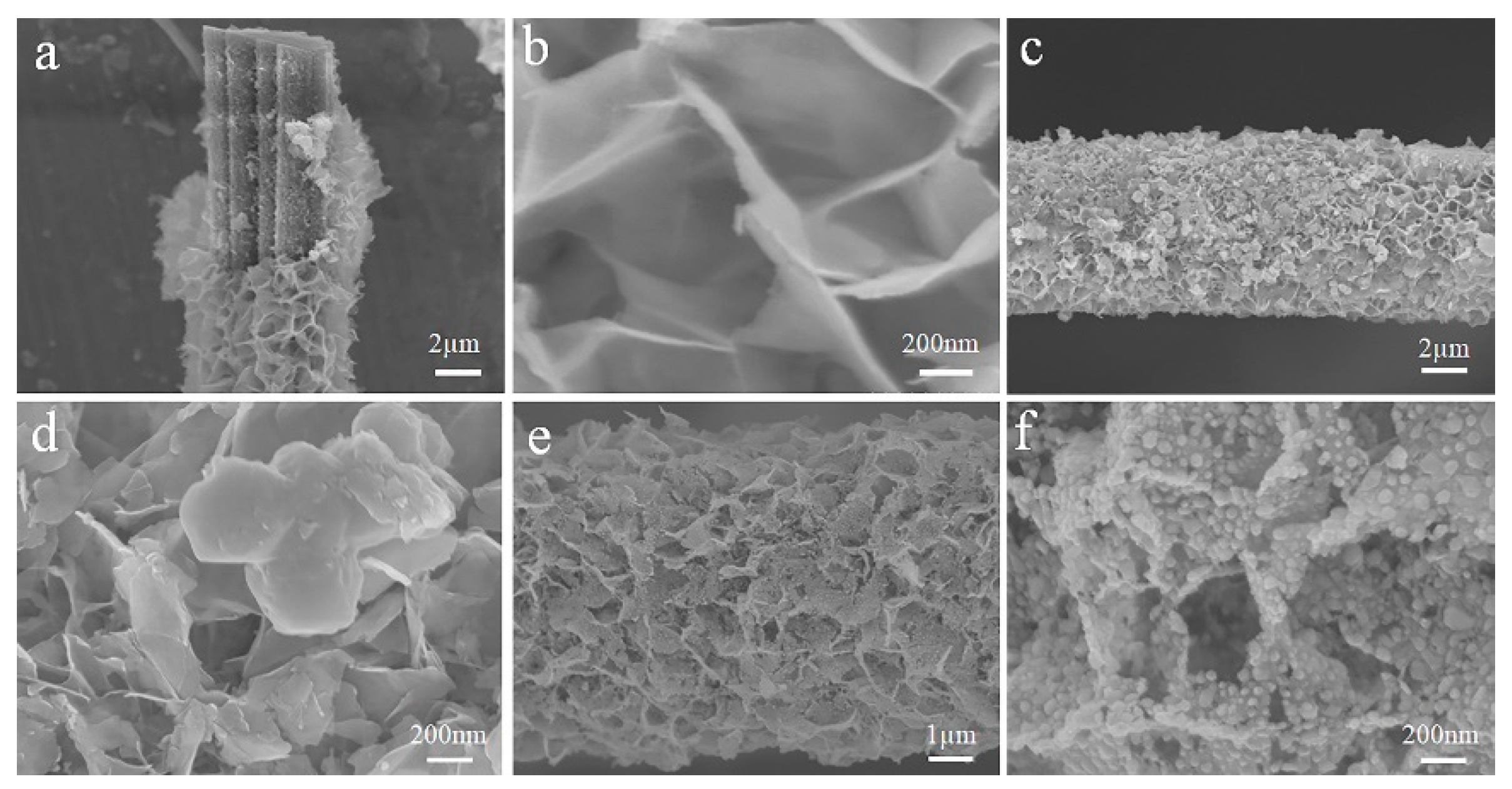
Figure 2 shows SEM images of Bi2O3/CFb, g-C3N4/Bi2O3/CFb and MoS2/g-C3N4/Bi2O3/CFb photocatalytic fiber specimens. SEM images of Bi2O3/CFb photocatalytic fiber specimens are shown in Figure 2a,b. From Figure 2a with the cross-sectional structure, it can be observed that Bi2O3/CFb photocatalytic fibers were in a core–shell structure, and carbon fibers prepared from bamboo pulp fibers with grooves were located in the middle of them. In combination with Figure 2b, it can be found that Bi2O3 nanoflakes formed a honeycomb structure, which was wrapped around the surface of the carbon fiber with a thickness of about 1.5 nm. In Figure 2a, the detachment of part of the Bi2O3 material was due to the detachment of part of the Bi2O3 wrapping layer when the carbon fibers were cut with small scissors during the preparation of the test samples. Figure 2c,d shows the SEM images of the g-C3N4/Bi2O3/CFb photocatalytic fiber specimens. It was clearly observed in Figure 2d with 50K times magnification that there were g-C3N4 nanosheets located on top of Bi2O3 nanosheets to form a honeycomb structure, and there were also some g-C3N4 nanosheets mixed with Bi2O3 nanosheets to form a honeycomb structure, which indicated that g-C3N4/Bi2O3/CFb photocatalytic composites had been successfully prepared. Figure 2e,f shows that it was obvious that there was some granular MoS2 distributed on the nanosheets of Bi2O3 and g-C3N4, and the size of MoS2 particles was about 50 nm, which indicated that MoS2 nanomaterials had been successfully loaded on the surface of g-C3N4/Bi2O3/CFb photocatalytic composites.
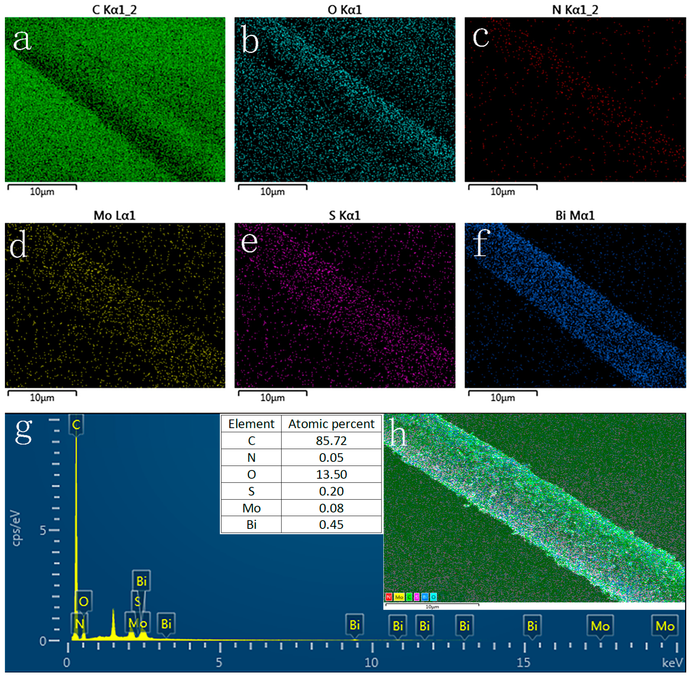
The elemental distribution of MoS2/g-C3N4/Bi2O3/CFb photocatalytic fibers was determined by SEM mapping. As shown in Figure 3, the elements Bi, Mo, S, and N were uniformly distributed on the surface of the carbon fibers, which also indicated that the preparation of MoS2/g-C3N4/Bi2O3/CFb photocatalytic fibers was successful.

3.2. Surface and Valence Bond Analysis of Materials

The surface chemical composition, chemical valence, and interaction relationships of MoS2/g-C3N4/Bi2O3/CFb photocatalytic fibers were analyzed by X-ray photoelectron spectroscopy (XPS). As shown in Figure 4a, the elements C, N, O, Bi, S, and Mo were mainly present on the surface of the MoS2/g-C3N4/Bi2O3/CFb photocatalytic fiber. From Figure 4b, it can be found that the fitted absorption peaks of C 1s in the MoS2/g-C3N4/Bi2O3/CFb specimen are located at 284.78 eV, 285.88 eV, and 289.07 eV, respectively, in which the C 1s peaks at 284.78 eV and 285.88 eV correspond to the C-C bond and C-O bond, respectively, in the carbon fiber formed by carbonization of bamboo pulp fiber [29,30], which should be attributed to the bonding of Bi2O3 with elemental C on the surface of the carbon fibers, whereas the C 1s peak at 289.07 should be attributed to the N-C-N in the six-membered ring of g-C3N4 with the sp2-hybridized carbon in N-C=N [31]. As shown in Figure 4c, the N 1s peak signals in g-C3N4 in composite fiber materials were relatively weak, mainly located at 398.89 eV, 399.79 eV, and 401.17 eV, which were attributed to the sp2-hybridized nitrogen N=CN, the amino acid group-NH2 bond on the surface of g-C3N4 materials, and the C-N bond [32], respectively. The presence of the N 1s peak indicated the existence of g-C3N4 material in the MoS2/g-C3N4/Bi2O3/CFb photocatalytic fiber. Figure 4d shows the O 1s absorption peaks at 530.95 eV and 532.25 eV, respectively; the O 1s peak at 530.95 eV was attributed to the lattice oxygen in the Bi2O3 material, and the peak at 532.25 eV was the surface adsorbed oxygen. As shown in Figure 4e, the binding energies of the 4f peaks of Bi were 159.99 eV and 165.32 eV, which corresponded to Bi 4f7/2 and Bi 4f5/2 of Bi 4f, respectively, with a difference of 5.33 eV between the two peaks, and the ratio of the two peaks’ areas was 4:3 [33,34]. Due to the comparatively low content of MoS2 in the composite photocatalytic fiber material, the S 2p peak located at 165.10 eV binding energy was weaker, which was attributed to the S 2p hybridization of S atoms in MoS2. From Figure 4f, it was found that the binding energies of the 3d peaks of Mo were 233.06 eV and 236.20 eV, which corresponded to Mo 3d5/2 and Mo 3d3/2, respectively, with a difference of 3.14 eV in binding energy between the two peaks, and the area ratio of the two peaks was 3:2. In summary, the above XPS characterization analysis further confirmed the successful preparation of MoS2/g-C3N4/Bi2O3/CFb photocatalytic fiber materials.

3.3. Thermogravimetric and Specific Surface Analysis of Materials

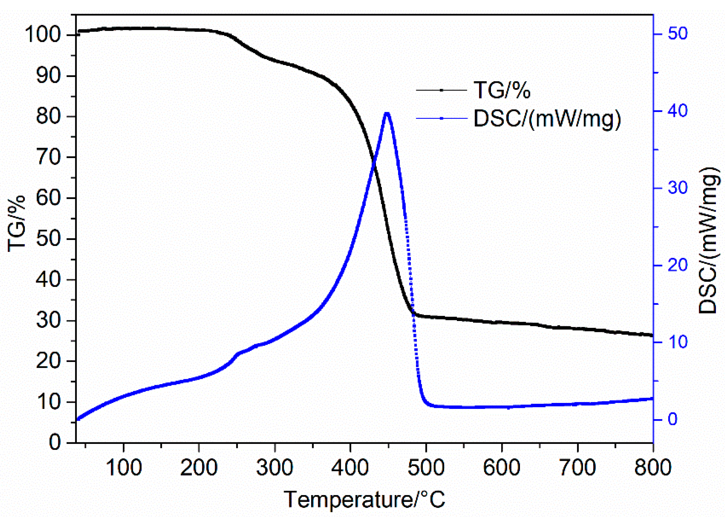
The TG-DSC test was used to determine the content of MoS2/g-C3N4/Bi2O3 in the MoS2/g-C3N4/Bi2O3/CFb photocatalytic composites. As shown in Figure 5, the weight of MoS2/g-C3N4/Bi2O3/CFb composites remained stable below 240 °C; with the increase in temperature, MoS2/g-C3N4/Bi2O3/CFb photocatalytic composites experienced an obvious weight loss phenomenon in the high temperature interval from 240 °C to 350 °C, and the weight loss rate was about 10%. It was presumed that the mass loss was partially attributed to the evaporation of moisture under elevated temperature conditions, with potential contributions from additional factors. In the temperature increase range of 350 °C to 495 °C, the MoS2/g-C3N4/Bi2O3/CFb photocatalytic composite underwent a cliff-like weight loss change, with a weight loss rate of up to about 60%, and a significant endothermic peak appeared. It was speculated that it was mainly formed by the combustion of carbon fibers in the composite material under the action of oxygen. After the temperature rose to 500 °C, the weight of the material gradually stabilized. Based on the above analysis, it can be inferred that the content of MoS2/g-C3N4/Bi2O3 in the MoS2/g-C3N4/Bi2O3/CFb accounted for about 28%.
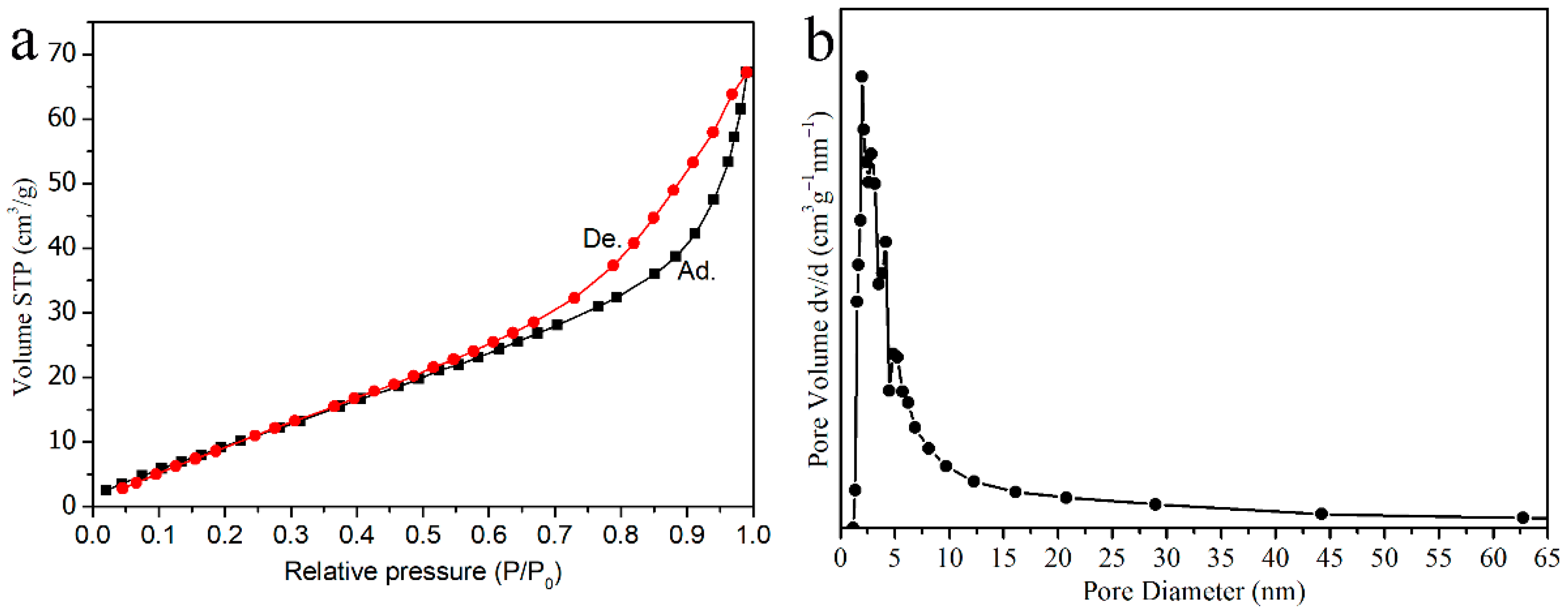
Figure 6 shows the nitrogen isothermal adsorption and desorption test of MoS2/g-C3N4/Bi2O3/CFb photocatalytic fiber. As shown in Figure 6a, the adsorption isotherms exhibited Type III behavior, and the specific surface area calculated by the BET (Brunauer–Emmett–Teller) method was approximately 77.919 cm2∙g−1. Both Bi2O3 and g-C3N4 were nanosheets that were loaded on the surface of the carbon fibers, and the shaped structure of the assembly resembled a honeycomb, so the MoS2/g-C3N4/Bi2O3/CFb photocatalytic composite fiber had a large specific surface area. The specific surface area is a crucial factor determining the adsorption capacity of reaction substrates. A larger surface area corresponds to greater adsorption capacity, which facilitates photocatalytic reactions occurring on the surface and consequently leads to higher catalytic activity. As shown in Figure 6b, the average pore size calculated using the BJH (Barrett–Joiner–Halenda) model was about 2.581 nm.

3.4. Results and Analysis of Degradation Experiments

Methylene blue (MB), a dye, was selected as the target pollutant and dissolved in an aqueous solution to evaluate the photocatalytic performance of Bi2O3/CFb, g-C3N4/Bi2O3/CFb, and MoS2/g-C3N4/Bi2O3/CFb photocatalytic fiber specimens through the organic dye degradation. As shown in Figure 7a, after 60 min of irradiation with a xenon lamp simulating sunlight, the removal of MB by Bi2O3/CFb was about 82%, and the removal of MB by g-C3N4/Bi2O3/CFb and MoS2/g-C3N4/Bi2O3/CFb was about 87% and 92%, respectively. g-C3N4 and MoS2 are both visible light photocatalysts. With the introduction of g-C3N4 and MoS2 as well as the formation of heterojunction structure with Bi2O3, the light absorption performance was enhanced, the separation and migration of photogenerated electron holes were improved, and the photocatalytic activity was significantly improved. It can be observed from Figure 7b that the degradation rates of MB by Bi2O3/CFb, g-C3N4/Bi2O3/CFb and MoS2/g-C3N4/Bi2O3/CFb obeyed the first-order reaction kinetics. The slope k, representing the first-order reaction rate constant, is an important parameter for evaluating photocatalytic activity. A higher k value indicates better photocatalytic performance.
To elucidate the photocatalytic mechanism of the MoS2/g-C3N4/Bi2O3/CFb composite photocatalytic fiber, radical trapping experiments were conducted using specific scavengers to identify the primary active species (h⁺, ·OH, and ·O2) responsible for the photocatalytic degradation. In this study, isopropanol (IPA), p-benzoquinone (BQ), and ammonium oxalate (AO) were employed as scavengers for ·OH, ·O2, and h⁺, respectively. As shown in Figure 8, the degradation rate of methylene blue (MB) varied upon the addition of different scavengers, following the trend: no scavenger > AO > IPA > BQ. The photocatalytic degradation efficiency of the MoS2/g-C3N4/Bi2O3/CFb composite fiber was significantly inhibited when BQ was added, indicating that ·O2 plays a dominant role in the photocatalytic process. Based on the experimental results, the order of contribution of the active species was determined as ·O2 > ·OH > h⁺, with ·O2 and ·OH being the most critical reactive species in the photocatalytic degradation mechanism.

3.5. Optical and Photoelectrochemical Properties of Materials

UV–vis DRS spectroscopy was used to study the light absorption properties of MoS2/g-C3N4/Bi2O3/CFb, g-C3N4/Bi2O3/CFb, Bi2O3/CFb, Bi2O3, Bi2O3, g-C3N4 as shown in Figure 9a. From the UV–vis DRS spectra of Bi2O3, it can be seen that the maximum UV absorption band edge of Bi2O3 material was around 375 nm. By comparing the UV–vis DRS spectra of Bi2O3/CFb and Bi2O3, we can see that Bi2O3/CFb photocatalytic fibers have strong light absorption performance in ultraviolet and visible light areas, which is attributed to the strong light absorption performance of black carbon fibers. When the introduction of g-C3N4, g-C3N4/Bi2O3/CFb obviously started to show a new light-absorbing bandwidth at 390 nm relative to the g-C3N4/Bi2O3 specimen, which was due to the fact that the maximal visible-light-absorbing bandwidth of g-C3N4 was at around 460 nm, which significantly improved the material’s light-absorbing performance. From the UV–vis DRS spectra of MoS2/g-C3N4/Bi2O3/CFb, it can be seen that the visible light absorption performance of the specimen was further enhanced with the introduction of MoS2 material, which was due to the fact that MoS2 was a narrow-bandwidth semiconducting material, and the previous studies of the group indicated that its bandwidth was about 1.37 eV [25], which was a very narrow bandwidth material. This property further improved the light absorption performance of MoS2/g-C3N4/Bi2O3/CFb. Therefore, we concluded that the introduction of g-C3N4 and MoS2 materials can significantly broaden the visible light response range of CFb/Bi2O3-based photocatalytic fibers, which was conducive to the excitation of photogenerated electrons and the enhancement of the photocatalytic performance of the composites.
Here, the bandgap of the photocatalysts can be calculated from the UV–vis diffuse reflectance spectra according to the Kubelka–Munk theory [35], as shown in Figure 9b. g-C3N4 is a direct bandgap semiconductor material, and the bandgap of g-C3N4 was calculated to be about 2.53 eV, while the bandgap of Bi2O3 was about 3.12 eV.
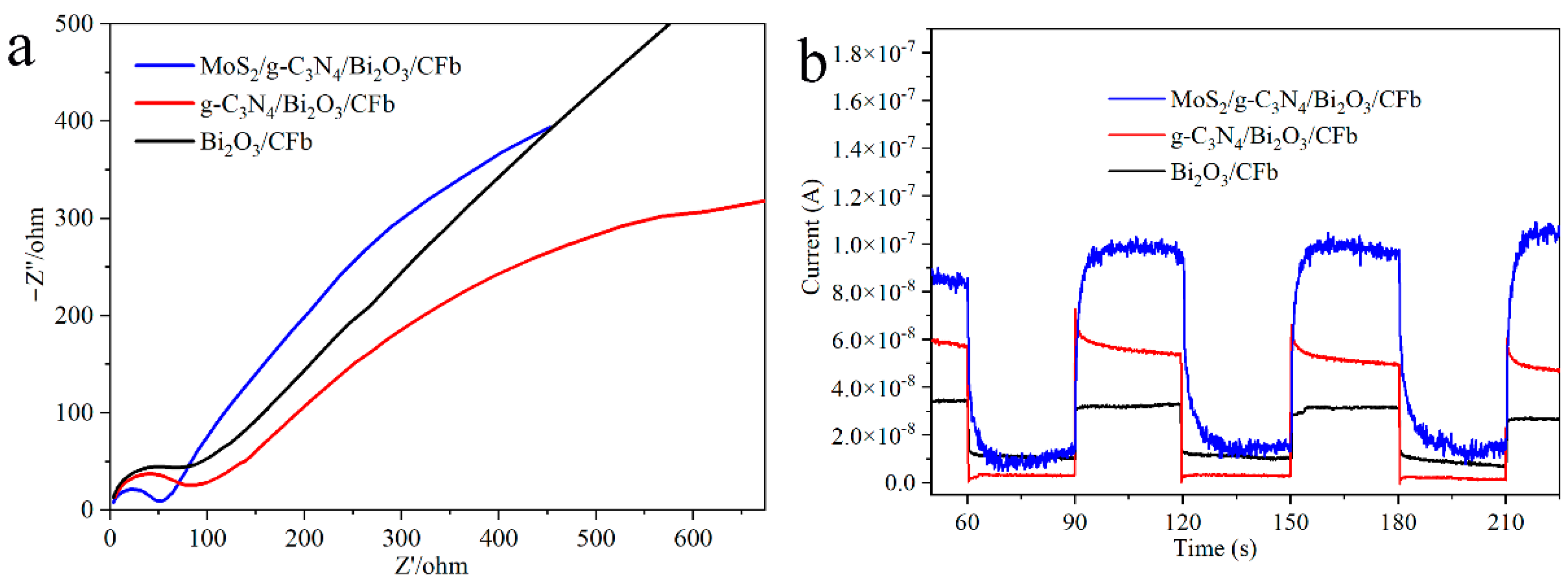
The separation of photogenerated electron hole pairs in photocatalytic fiber materials was analyzed by electrochemical impedance spectroscopy (EIS) and transient photocurrent response (I-t) tests. As shown in Figure 10a, in the high-frequency region of the AC impedance spectrum, the arc radii of Bi2O3/CFb, g-C3N4/Bi2O3/CFb, and MoS2/g-C3N4/Bi2O3/CFb specimens gradually decreased. A smaller arc radius indicates lower charge transfer resistance, faster carrier migration, and higher photogenerated electron hole pair separation efficiency, thereby enhancing photocatalytic performance. Therefore, with the introduction of g-C3N4 and MoS2 materials, the photocatalytic performance of the composite fiber materials will be further improved. From Figure 10b, it can be found that the transient photocurrents of Bi2O3/CFb, g-C3N4/Bi2O3/CFb, and MoS2/g-C3N4/Bi2O3/CFb specimens were increased in order, which were about 3.1 × 10⁻⁸ A, 5.4 × 10⁻⁸ A and 9.9 × 10⁻⁸ A, indicating that g-C3N4 and MoS2 materials improved the charge separation efficiency of MoS2/g-C3N4/Bi2O3/CFb composite fibers. The photocurrent response of the MoS2/g-C3N4/Bi2O3/CFb samples had the strongest photocurrent response, and the corresponding photogenerated electron hole pair had the fastest separation speed, the lowest recombination rate, and the highest migration efficiency of photogenerated carriers.
In summary, combined with the previous experimental results of photocatalytic degradation, it was shown that with the introduction and loading of g-C3N4 and MoS2 materials, the separation and migration of photogenerated electron hole pairs were significantly improved, and the compounding of photogenerated electron hole pairs was effectively prevented, which improved the photocatalytic performance of the composite fiber materials.
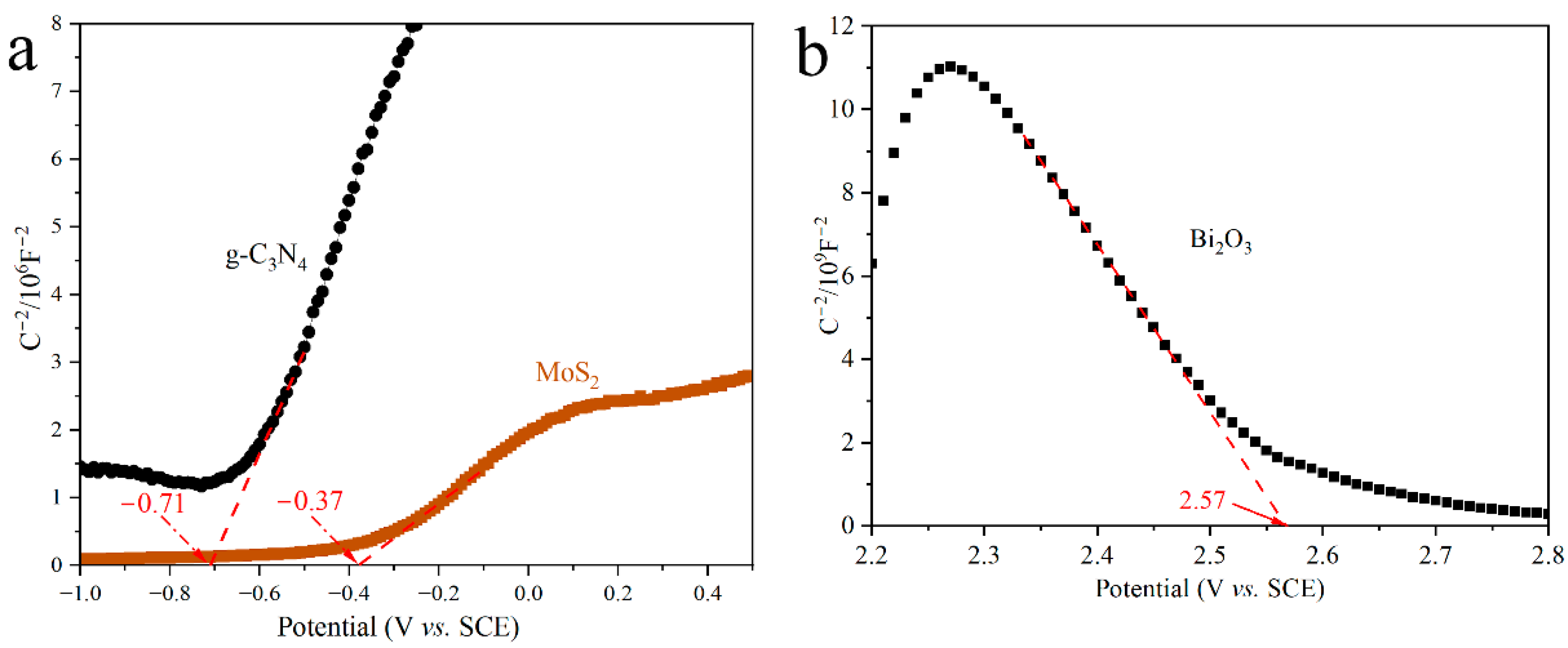
The semiconductor types and energy band potentials of g-C3N4, MoS2 and Bi2O3 were further investigated using electrochemical Mott–Schottky experiments. As shown in Figure 11a, the Mott–Schottky curves for g-C3N4 and MoS2 exhibit positive slopes, which suggests that both g-C3N4 and MoS2 were typical n-type semiconductors. The flat band potentials for g-C3N4 and MoS2 can be inferred to be −0.71 V (vs. SCE) and −0.37 V (vs. SCE). It is known that the bandgap widths of g-C3N4 and MoS2 are 2.53 eV and 1.37 eV, respectively. Based on the potential relationship between the standard hydrogen electrode and the saturated calomel electrode [36], it can be seen that the Fermi level, valence band (VB) position, and conduction band (CB) position of g-C3N4 were −0.57 eV, 1.86 eV, and −0.67 eV, respectively, while the Fermi level, valence band (VB) position, and conduction band (CB) position of MoS2 were −0.13 eV, 1.14 eV, and −0.23 eV, respectively. As shown in Figure 11b, the slope of the Mott–Schottky curve for Bi2O3 was negative, which suggested that Bi2O3 is a p-type semiconductor material, and the flat band potential was 2.57 V (vs. SCE). The Fermi level, valence band (VB) position, and conduction band (CB) position of Bi2O3 were calculated to be 2.91 eV, 3.01 eV, and −0.11 eV, respectively.

3.6. Analysis of Photocatalytic Degradation Mechanism

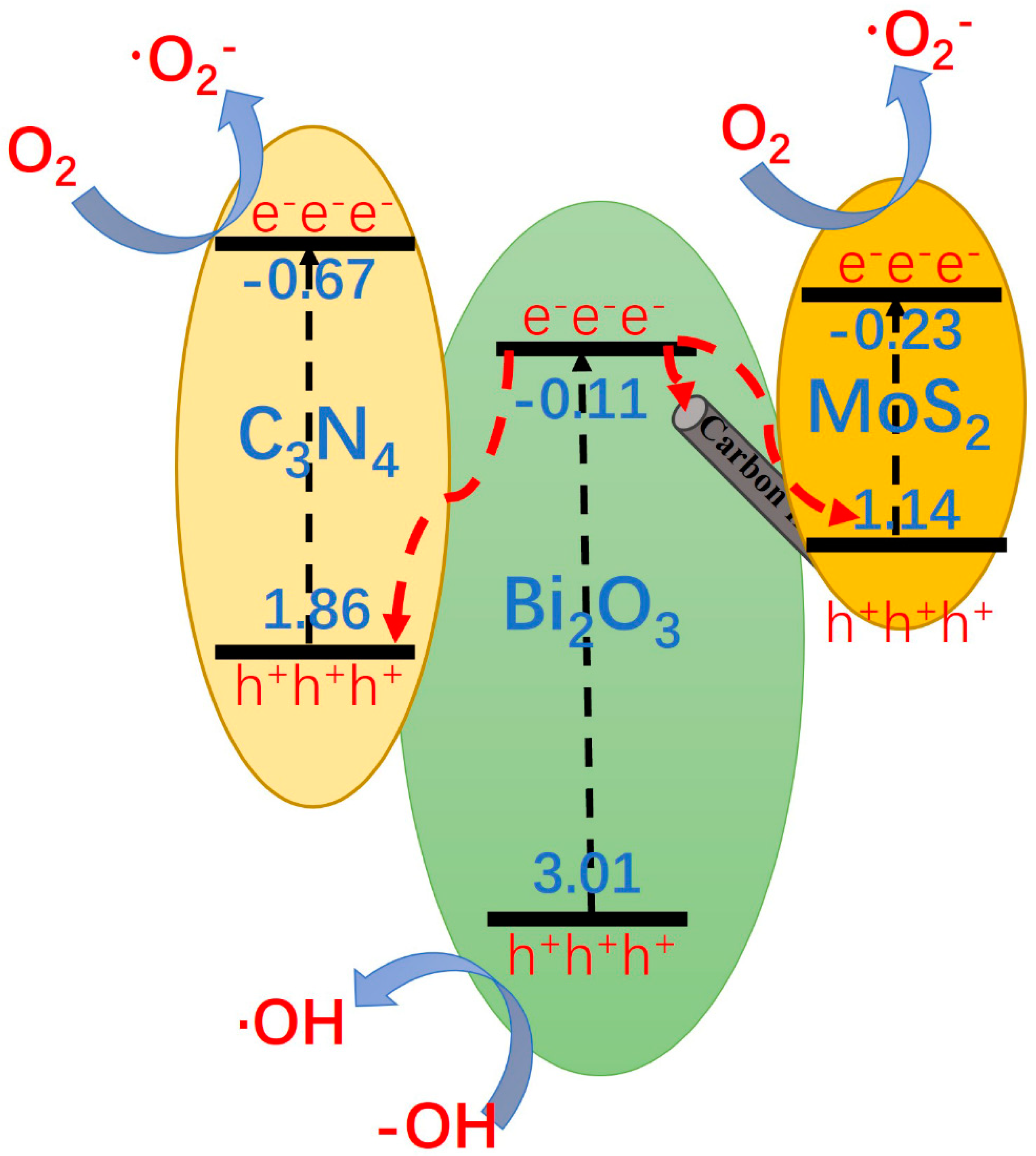
Based on the previous tests and analyses and in conjunction with the literature, the photocatalytic degradation mechanism of MoS2/g-C3N4/Bi2O3/CFb composite photocatalytic fibers was proposed, and the process of charge transfer was shown in Figure 12.
Under the effect of light, electrons (e) in the valence bands of photocatalysts Bi2O3, g-C3N4, and MoS2 are excited to their conduction bands, while holes (h⁺) are generated in the valence bands. Most researchers suggest that a Z-scheme heterojunction forms upon the combination of Bi2O3 with g-C3N4 [14,37,38,39,40,41]. In this study, the introduction of g-C3N4 and its subsequent combination with Bi2O3 improved the photocatalytic performance of g-C3N4/Bi2O3/CFb. This enhancement is attributed to the Z-scheme heterojunction formed between g-C3N4 and Bi2O3, wherein photogenerated electrons in the conduction band of Bi2O3 recombine with holes in the valence band of g-C3N4, while photogenerated electrons in the conduction band of g-C3N4 migrate to the material surface. On the other hand, g-C3N4 that has a narrow bandgap can excite photogenerated carriers just under visible light, which improves the light absorption range. From Figure 2 above, it can be observed that most of the surfaces of g-C3N4/Bi2O3/CFb fibers were Bi2O3 nanosheets, with a small amount of g-C3N4 nanosheets. After the introduction of MoS2 nanodots, MoS2 was mainly loaded on the surface of Bi2O3 nanosheets. The combination of MoS2 and Bi2O3 is widely accepted to generate a Z-scheme heterojunction [42,43,44]. The valence band of MoS2 (VB) position was about 1.14 eV, which was closer to the conduction band position of Bi2O3 material. MoS2 and Bi2O3 formed a Z-scheme heterojunction, and the photogenerated electrons on the conduction band of Bi2O3 were complexed with the holes on the valence band of MoS2. The photogenerated electrons on the conduction band of MoS2, and the holes on the valence band of Bi2O3 migrated, respectively, toward the surface of the material. The carbon fiber was located in the middle core of the composite photocatalytic fiber, and part of the electrons on the Bi2O3 conduction band migrated toward the surface of the carbon fiber. In summary, the photocatalyst on the surface of the MoS2/g-C3N4/Bi2O3/CFb composite photocatalytic fiber constituted a double Z-scheme heterojunction. According to the previous analysis of the photogenerated carrier transfer process, the photogenerated electrons on the g-C3N4 and MoS2 conduction bands migrated to the surface of the material, which contacted with O2 that adsorbed in water or on the surface of the material to form -O2-, while the holes on the valence band (h+) of Bi2O3 migrated to the surface of the material, which contacted with -OH adsorbed in water or on the surface of the material to form -OH, and then -O2-, -OH, and h+ degraded MB in water and decomposed into small-molecular materials such as CO2 and H2O [45].

4. Conclusions

In this study, ternary and bilayer core–shell structure MoS2/g-C3N4/Bi2O3/CFb photocatalytic fibers were constructed on the surface of carbon fibers by solvent-thermal and impregnation methods. The photocatalytic degradation experiments of MB demonstrated that with the introduction of the visible light photocatalysts g-C3N4 and MoS2 with narrow bandgap, the light absorption performance was enhanced, and the separation and migration of photogenerated electron holes were improved, which significantly increased the photocatalytic degradation activity, and the removal rate of MB by MoS2/g-C3N4/Bi2O3/CFb was about 92%. Through the analysis of energy band structure and active species, it was proposed that g-C3N4 and Bi2O3 and MoS2 and Bi2O3 were Z-scheme heterojunctions. This dual Z-scheme configuration involves two reductive semiconductors and two oxidative semiconductors, leading to a synergistic enhancement of the overall redox potentials and thereby endowing the photocatalytic material with stronger oxidizing and reducing activity. The construction method of dual Z-scheme heterojunction provided a new research idea and reference for the design and preparation of novel multifunctional composite photocatalytic materials.

Author Contributions

Methodology, J.N. and J.P.; Formal analysis, J.P.; Investigation, J.N. and B.Z.; Data curation, J.N., J.P. and B.Z.; Writing—original draft, J.N.; Writing #x2014;review & editing, J.N.; Supervision, C.L.; Project administration, C.L.; Funding acquisition, C.L. All authors have read and agreed to the published version of the manuscript.

Funding

This research was supported in part by the Natural Science Foundation of Jiangsu Province (BK20231205), and in part by the “Qinglan Project” of Jiangsu Province in China under Grant 2024.

Institutional Review Board Statement

Not applicable.

Informed Consent Statement

Not applicable.

Data Availability Statement

Data are contained within the article.

Conflicts of Interest

The authors declare no conflict of interest.

References

  1. El Messaoudi, N.; Miyah, Y.; Singh, N.; Gubernat, S.; Fatima, R.; Georgin, J.; El Mouden, A.; Saghir, S.; Knani, S.; Hwang, Y. A critical review of Allura Red removal from water: Advancements in adsorption and photocatalytic degradation technologies, and future perspectives. J. Environ. Chem. Eng. 2024, 12, 114843. [Google Scholar] [CrossRef]
  2. Wang, W.; Yang, R.; Li, T.; Komarneni, S.; Liu, B. Advances in recyclable and superior photocatalytic fibers: Material, construction, application and future perspective. Compos. Part B Eng. 2021, 205, 108512. [Google Scholar] [CrossRef]
  3. Zhang, N.; Yang, M.-Q.; Liu, S.; Sun, Y.; Xu, Y.-J. Waltzing with the versatile platform of graphene to synthesize composite photocatalysts. Chem. Rev. 2015, 115, 10307–10377. [Google Scholar] [CrossRef]
  4. Zhang, P.; Yin, L.; Yang, X.; Wang, J.; Chi, M.; Qiu, J. Cotton-derived 3D carbon fiber aerogel to in situ support Bi2O3 nanoparticles as a separation-free photocatalyst for antibiotic removal. Carbon 2023, 201, 110–119. [Google Scholar] [CrossRef]
  5. Cao, N.; Gu, M.; Gao, M.; Li, C.; Liu, K.; Zhao, X.; Feng, J.; Ren, Y.; Wei, T. A three-layer photocatalyst carbon fibers/TiO2 seed/TiO2 nanorods with high photocatalytic degradation under visible light. Appl. Surf. Sci. 2020, 530, 147289. [Google Scholar] [CrossRef]
  6. Luo, Y.; Kim, K.-D.; Seo, H.O.; Kim, M.J.; Tai, W.S.; Lee, K.H.; Lim, D.C.; Kim, Y.D. Photocatalytic Decomposition of Toluene Vapor by Bare and TiO2-coated Carbon Fibers. Bull. Korean Chem. Soc. 2010, 31, 1661–1664. [Google Scholar] [CrossRef]
  7. Yuan, R.S.; Guan, R.B.; Zheng, J.T. Effect of the pore size of TiO2-loaded activated carbon fiber on its photocatalytic activity. Scr. Mater. 2005, 52, 1329–1334. [Google Scholar] [CrossRef]
  8. Zhou, S.; Wang, J. Carbon-doped Oxygen-deficient TiO2 Fibers Synthesized without Adding External Carbon Sources and Their Photocatalytic Activity. Chem. J. Chin. Univ. Chin. 2021, 42, 1284–1291. [Google Scholar] [CrossRef]
  9. Fu, Y.; Jin, X.; Ni, Q. Preparation and Characterization of Pd-TiO2 Photocatalytic Materials Supported by Carbon Fibers. Rare Met. Mater. Eng. 2010, 39, 1075–1078. [Google Scholar]
  10. Yang, Y.; Chen, H.; Zou, X.; Shi, X.-L.; Liu, W.-D.; Feng, L.; Suo, G.; Hou, X.; Ye, X.; Zhang, L.; et al. Flexible Carbon-Fiber/Semimetal Bi Nanosheet Arrays as Separable and Recyclable Plasmonic Photocatalysts and Photoelectrocatalysts. ACS Appl. Mater. Interfaces 2020, 12, 24845–24854. [Google Scholar] [CrossRef]
  11. Ma, J.; Chen, J.; Wang, B.; Cai, S. The in-situ growth of BiVO4 coatings on carbon fibers and their photocatalytic performance. Mater. Res. Bull. 2016, 77, 253–257. [Google Scholar] [CrossRef]
  12. Han, C.; Jing, M.-X.; Yang, H.; Shen, X.-Q.; Qiao, G.-J. An Overlapped Nano-Fe2O3/TiO2 Composite Coating on Activated Carbon Fiber Membrane with Enhanced Photocatalytic Performance. J. Nanosci. Nanotechnol. 2019, 19, 7123–7130. [Google Scholar] [CrossRef] [PubMed]
  13. Zahid, A.H.; Han, Q. A review on the preparation, microstructure, and photocatalytic performance of Bi2O3 in polymorphs. Nanoscale 2021, 13, 17687–17724. [Google Scholar] [CrossRef] [PubMed]
  14. Zhang, J.; Hu, Y.; Jiang, X.; Chen, S.; Meng, S.; Fu, X. Design of a direct Z-scheme photocatalyst: Preparation and characterization of Bi2O3/g-C3N4 with high visible light activity. J. Hazard. Mater. 2014, 280, 713–722. [Google Scholar] [CrossRef] [PubMed]
  15. Lu, P.; Peng, Y.; Yang, Y.; Chen, S.; Shang, J.; Yang, C.; Xu, M.; Bai, J.; Zhao, Z.; Hu, X. Visible-light-driven photocatalytic for degrading tetracycline wastewater by BiOI/Bi2O3 Z-scheme heterojunction. J. Environ. Chem. Eng. 2024, 12, 114395. [Google Scholar] [CrossRef]
  16. Wang, X.; Du, C.; Yu, Y.; Li, W.; Li, T.; Wang, S.; Mao, S.; Wang, Y.; Zhao, J.; Xiong, C. Efficient photocatalytic degradation with a lattice-matched α-Bi2O3/Co3O4 Z-scheme heterojunction: An integrated experimental and DFT study. J. Water Process Eng. 2024, 65, 105829. [Google Scholar] [CrossRef]
  17. Wang, Q.; Zhao, S.; Zhao, Y.; Deng, Y.; Yang, W.; Ye, Y.; Wang, K. Construction of Z-scheme Bi2O3/CeO2 heterojunction for enhanced photocatalytic capacity of TiO2 NTs. Spectrochim. Acta Part A Mol. Biomol. Spectrosc. 2024, 304, 123405. [Google Scholar] [CrossRef]
  18. Liu, Y.; Liu, D.; Huang, B.; Chen, Y.; Li, X.; Chen, L.; Dan, Y. Bi2O3@MoS2 heterojunction for enhanced photoelectrocatalytic hydrogen evolution. J. Electroanal. Chem. 2024, 957, 118127. [Google Scholar] [CrossRef]
  19. Fu, J.; Cao, S.; Yu, J. Dual Z-scheme charge transfer in TiO2–Ag–Cu2O composite for enhanced photocatalytic hydrogen generation. J. Mater. 2015, 1, 124–133. [Google Scholar] [CrossRef]
  20. Kumar, A.; Sharma, G.; Kumari, A.; Guo, C.; Naushad, M.; Vo, D.-V.N.; Iqbal, J.; Stadler, F.J. Construction of dual Z-scheme g-C3N4/Bi4Ti3O12/Bi4O5I2 heterojunction for visible and solar powered coupled photocatalytic antibiotic degradation and hydrogen production: Boosting via I/I3− and Bi3+/Bi5+ redox mediators. Appl. Catal. B Environ. 2021, 284, 119808. [Google Scholar] [CrossRef]
  21. Li, X.; Sun, H.; Xie, Y.; Liang, Y.; Gong, X.; Qin, P.; Jiang, L.; Guo, J.; Liu, C.; Wu, Z. Principles, synthesis and applications of dual Z-scheme photocatalysts. Coord. Chem. Rev. 2022, 467, 214596. [Google Scholar] [CrossRef]
  22. Malefane, M.E.; Mafa, P.J.; Managa, M.; Nkambule, T.T.; Kuvarega, A.T. Understanding the principles and applications of dual Z-scheme heterojunctions: How far can we go? J. Phys. Chem. Lett. 2023, 14, 1029–1045. [Google Scholar] [CrossRef] [PubMed]
  23. Feng, J.; Jiang, T.; Han, Y.; Okoth, O.K.; Cheng, L.; Zhang, J. Construction of dual Z-scheme Bi2S3/Bi2O3/WO3 ternary film with enhanced visible light photoelectrocatalytic performance. Appl. Surf. Sci. 2020, 505, 144632. [Google Scholar] [CrossRef]
  24. Wang, Q.; Li, N.; Tan, M.; Deng, M.; Yang, G.; Li, Q.; Du, H. Novel dual Z-scheme Bi/BiOI-Bi2O3-C3N4 heterojunctions with synergistic boosted photocatalytic degradation of phenol. Sep. Purif. Technol. 2023, 307, 122733. [Google Scholar] [CrossRef]
  25. Pan, J.; Wang, P.; Chen, Z.; Yu, Q.; Wang, P.; Zhu, M.; Zhao, W.; Wang, J.; Zheng, Y.; Li, C. The Pt-free 1T/2H-MoS2/CdS/MnOx hollow core-shell nanocomposites toward overall water splitting via HER/OER synergy of 1T-MoS2/MnOx. Mater. Today Chem. 2021, 21, 100528. [Google Scholar] [CrossRef]
  26. Ou, W.; Pan, J.; Liu, Y.; Li, S.; Li, H.; Zhao, W.; Wang, J.; Song, C.; Zheng, Y.; Li, C. Two-dimensional ultrathin MoS2-modified black Ti3+–TiO2 nanotubes for enhanced photocatalytic water splitting hydrogen production. J. Energy Chem. 2020, 43, 188–194. [Google Scholar] [CrossRef]
  27. Zhao, T.; Yang, Z.; Liu, Y.; Li, Y.; Zeng, K.; Zhao, C.; Yu, J.; Cai, L.; Zhang, R. Novel Bi2S3/Bi2WO6 nanomaterials with 2D/3D spatial structure stably degrade veterinary antibiotics under visible light. J. Phys. Chem. Solids 2021, 155, 110106. [Google Scholar] [CrossRef]
  28. Mishra, B.P.; Babu, P.; Parida, K. Phosphorous, boron and sulfur doped g-C3N4 nanosheet: Synthesis, characterization, and comparative study towards photocatalytic hydrogen generation. Mater. Today Proc. 2021, 35, 258–262. [Google Scholar] [CrossRef]
  29. Song, B.; Wang, T.; Wang, L.; Liu, H.; Mai, X.; Wang, X.; Wang, N.; Huang, Y.; Ma, Y.; Lu, Y. Interfacially reinforced carbon fiber/epoxy composite laminates via in-situ synthesized graphitic carbon nitride (g-C3N4). Compos. Part B Eng. 2019, 158, 259–268. [Google Scholar] [CrossRef]
  30. Thanh Ngoc, N.; Vinh Van, T.; Vu Khac Hoang, B.; Kim, M.; Park, D.; Hur, J.; Kim, I.T.; Lee, H.U.; Ko, S.; Lee, Y.-C. A Novel Photocatalyst Composite of Magnesium Aminoclay and TiO2 Immobilized into Activated Carbon Fiber (ACF) Matrix for Pollutant Removal. J. Nanosci. Nanotechnol. 2020, 20, 6844–6849. [Google Scholar] [CrossRef]
  31. Song, B.; Wang, T.; Sun, H.; Liu, H.; Mai, X.; Wang, X.; Wang, L.; Wang, N.; Huang, Y.; Guo, Z. Graphitic carbon nitride (g-C3N4) interfacially strengthened carbon fiber epoxy composites. Compos. Sci. Technol. 2018, 167, 515–521. [Google Scholar] [CrossRef]
  32. Shen, X.; Song, B.; Shen, X.; Shen, C.; Shan, S.; Xue, Q.; Chen, X.; Li, S. Rationally designed S-scheme heterojunction of C3N4/Bi2MoO6/carbon fiber cloth as a recyclable, macroscopic and efficient photocatalyst for wastewater treatment. Chem. Eng. J. 2022, 445, 136703. [Google Scholar] [CrossRef]
  33. Kumari, P.; Ghosh, S.K.; Perla, V.K.; Saha, C.; Singh, H.; Mallick, K. Nanostructured bismuth phosphate-based asymmetric supercapacitor: Electrochemical evaluation and oscillator application. J. Mater. Sci. Mater. Electron. 2024, 35, 1882. [Google Scholar] [CrossRef]
  34. Jia, Y.; Li, S.; Gao, J.; Zhu, G.; Zhang, F.; Shi, X.; Huang, Y.; Liu, C. Highly efficient (BiO)2CO3-BiO2-x-graphene photocatalysts: Z-Scheme photocatalytic mechanism for their enhanced photocatalytic removal of NO. Appl. Catal. B Environ. 2019, 240, 241–252. [Google Scholar] [CrossRef]
  35. Li, X.; He, C.; Zuo, S.; Yan, X.; Dai, D.; Zhang, Y.; Yao, C. Photocatalytic nitrogen fixation over fluoride/attapulgite nanocomposite: Effect of upconversion and fluorine vacancy. Sol. Energy 2019, 191, 251–262. [Google Scholar] [CrossRef]
  36. Gong, H.; Zhang, X.; Wang, G.; Liu, Y.; Li, Y.; Jin, Z. Dodecahedron ZIF-67 anchoring ZnCdS particles for photocatalytic hydrogen evolution. Mol. Catal. 2020, 485, 110832. [Google Scholar] [CrossRef]
  37. He, R.; Zhou, J.; Fu, H.; Zhang, S.; Jiang, C. Room-temperature in situ fabrication of Bi2O3/g-C3N4 direct Z-scheme photocatalyst with enhanced photocatalytic activity. Appl. Surf. Sci. 2018, 430, 273–282. [Google Scholar] [CrossRef]
  38. Ranjith, R.; Vignesh, S.; Balachandar, R.; Suganthi, S.; Raj, V.; Ramasundaram, S.; Sundar, J.K.; Shkir, M.; Oh, T.H. Construction of novel g-C3N4 coupled efficient Bi2O3 nanoparticles for improved Z-scheme photocatalytic removal of environmental wastewater contaminant: Insight mechanism. J. Environ. Manag. 2023, 330, 117134. [Google Scholar] [CrossRef]
  39. Lu, S.; Wu, T.; Liu, Y.; Luo, H.; Jiang, F.; Nie, X.; Chen, H. All-solid Z-scheme Bi/γ-Bi2O3/O-doped g-C3N4 heterojunction with Bi as electron shuttle for visible-light photocatalysis. J. Alloys Compd. 2022, 911, 164980. [Google Scholar] [CrossRef]
  40. Kumar, R.; Sudhaik, A.; Kumar, D.; Devi, R.; Devi, E.; Chawla, A.; Raizada, P.; Hussain, C.M.; Ahamad, T.; Singh, P. Synergistic photocatalytic activity of Bi2O3/g-C3N4/ZnO ternary heterojunction with dual Z-scheme charge transfer towards textile dye degradation. J. Ind. Eng. Chem. 2025, 144, 575–584. [Google Scholar] [CrossRef]
  41. Zeng, X.; Wang, X.; Shu, S.; Zhang, R.; Chen, J.; Wang, Y. Constructing a Z-scheme (3-Bi2O3/g-C3N4 heterojunction with enhancing photocatalytic activity for sulfamethoxypyridazine degradation. Mater. Sci. Semicond. Process. 2025, 189, 109273. [Google Scholar] [CrossRef]
  42. Goud, B.S.; Koyyada, G.; Jung, J.H.; Reddy, G.R.; Shim, J.; Nam, N.D.; Vattikuti, S.P. Surface oxygen vacancy facilitated Z-scheme MoS2/Bi2O3 heterojunction for enhanced visible-light driven photocatalysis-pollutant degradation and hydrogen production. Int. J. Hydrogen Energy 2020, 45, 18961–18975. [Google Scholar] [CrossRef]
  43. Ji, R.; Ma, C.; Ma, W.; Liu, Y.; Zhu, Z.; Yan, Y. Z-scheme MoS2/Bi2O3 heterojunctions: Enhanced photocatalytic degradation performance and mechanistic insight. New J. Chem. 2019, 43, 11876–11886. [Google Scholar] [CrossRef]
  44. Qureshi, M.T.; Mushtaq, A.; Farooq, U.; Basit, A.; Iqbal, T.; Younas, A.; Al Elaimi, M.; Affan, H.; Othman, M.S.; Yunus, G. Facile Strategies to Fabricate MoS2/Bi2O3 Nanocomposites; A Nano Engineered Material for Photoassisted Degradation of Ciprofloxacin and Their Antibacterial Performance. J. Inorg. Organomet. Polym. Mater. 2024, 1–16. [Google Scholar] [CrossRef]
  45. Li, C.X.; Song, S.Y.; Shi, D.S.; Yhig, Y.; Zhang, X.X.; Wei, J.Q.; Hong, B.; Xu, J.C.; Jin, H.X.; Wang, P.F.; et al. Improved photocatalytic activity of Z-scheme β-Bi2O3/Bi2WO6 nanocomposites from band bending of p-n heterojunction. J. Nanopart. Res. 2020, 22, 123. [Google Scholar] [CrossRef]
Figure 1. XRD pattern of samples.
Coatings 15 00447 g001
Figure 2. SEM images of the specimens: (a,b) Bi2O3/CFb photocatalytic fiber, (c,d) g-C3N4/Bi2O3/CFb photocatalytic fiber, (e,f) MoS2/g-C3N4/Bi2O3/CFb photocatalytic fiber.
Coatings 15 00447 g002
Figure 3. Elemental distribution of MoS2/g-C3N4/Bi2O3/CFb photocatalytic fibers. (a) C element, (b) O element, (c) N element, (d) Mo element, (e) S element, (f) Bi element, (g) element content diagram, (h) SEM diagram of composite fiber.
Coatings 15 00447 g003
Figure 4. XPS spectrum of the MoS2/g-C3N4/Bi2O3/CFb photocatalytic fiber. (a) full spectrum, (b) C 1S spectrum, (c) N 1S spectrum, (d) O 1S spectrum, (e) Bi 4f and S 2p spectrum, (f) Mo 3d spectrum.
Coatings 15 00447 g004
Figure 5. TG-DSC curves of MoS2/g-C3N4/Bi2O3/CFb photocatalytic fibers.
Coatings 15 00447 g005
Figure 6. Oxygen adsorption–desorption isotherms (a) and mesopore distribution (b) for MoS2/g-C3N4/Bi2O3/CFb.
Coatings 15 00447 g006
Figure 7. Photocatalytic degradation rate of MB by different catalysts (a) and the corresponding kinetics curves (b).
Coatings 15 00447 g007
Figure 8. Detection of active species during the degradation process.
Coatings 15 00447 g008
Figure 9. UV–vis DRS spectra (a) and bandgap width (b) of specimens.
Coatings 15 00447 g009
Figure 10. Impedance spectra (a) and transient photocurrent response spectra (b) of composite fiber specimens.
Coatings 15 00447 g010
Figure 11. Mott–Schottky plots for specimens g-C3N4 and MoS2 (a) and Bi2O3 (b).
Coatings 15 00447 g011
Figure 12. Schematic diagram of possible charge transfer during the photocatalytic degradation of MoS2/g-C3N4/Bi2O3/CFb.
Coatings 15 00447 g012
Disclaimer/Publisher’s Note: The statements, opinions and data contained in all publications are solely those of the individual author(s) and contributor(s) and not of MDPI and/or the editor(s). MDPI and/or the editor(s) disclaim responsibility for any injury to people or property resulting from any ideas, methods, instructions or products referred to in the content.